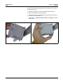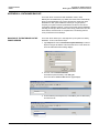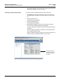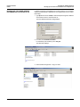
1
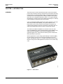
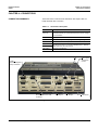
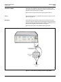
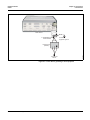
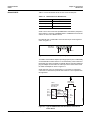
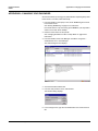
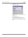
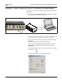
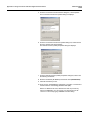
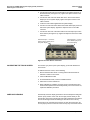
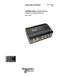
Instruction Bulletin 63230-216-207/A3 9/2002 Replaces 63230-216-207/A2 dated January 2002 POWERLOGIC® Power Server PWRSRV710 and PWRSRV750 Models Setup Guide Retain for future use. NOTICE Read these instructions carefully and look at the equipment to become familiar with the device before trying to install, operate, or maintain it. The following special messages may appear throughout this bulletin or on the equipment to warn of potential hazards or to call attention to information that clarifies or simplifies a procedure. The addition of either symbol to a “Danger” or “Warning” safety label indicates that an electrical hazard exists which will result in personal injury if the instructions are not followed. This is the safety alert symbol. It is used to alert you to potential personal injury hazards. Obey all safety messages that follow this symbol to avoid possible injury or death. DANGER DANGER indicates an imminently hazardous situation which, if not avoided, will result in death or serious injury. WARNING WARNING indicates a potentially hazardous situation which, if not avoided, can result in death or serious injury. CAUTION CAUTION indicates a potentially hazardous situation which, if not avoided, can result in minor or moderate injury. CAUTION CAUTION, used without the safety alert symbol, indicates a potentially hazardous situation which, if not avoided, can result in property damage. NOTE: Provides additional information to clarify or simplify a procedure. PLEASE NOTE Electrical equipment should be installed, operated, serviced, and maintained only by qualified personnel. This document is not intended as an instruction manual for untrained persons. No responsibility is assumed by Square D for any consequences arising out of the use of this manual. CLASS A FCC STATEMENT This equipment has been tested and found to comply with the limits for a Class A digital device, pursuant to part 15 of the FCC Rules. These limits are designated to provide reasonable protection against harmful interference when the equipment is operated in a commercial environment. This equipment generates, uses, and can radiate radio frequency energy and, if not installed and used in accordance with the instruction manual, may cause harmful interference to radio communications. Operation of this equipment in a residential area is likely to cause harmful interference in which case the user will be required to correct the interference at his own expense. 63230-216-207/A3 9/2002 CONTENTS Contents CHAPTER 1—INTRODUCTION . . . . . . . . . . . . . . . . . . . . . . . . . . . . . . . . 1 Overview . . . . . . . . . . . . . . . . . . . . . . . . . . . . . . . . . . . . . . . . . . . . . . . . . . . 1 CHAPTER 2—SAFETY PRECAUTIONS . . . . . . . . . . . . . . . . . . . . . . . . . . 3 CHAPTER 3—INSTALLATION . . . . . . . . . . . . . . . . . . . . . . . . . . . . . . . . . 5 Dimensions . . . . . . . . . . . . . . . . . . . . . . . . . . . . . . . . . . . . . . . . . . . . . . . . . 5 Mounting . . . . . . . . . . . . . . . . . . . . . . . . . . . . . . . . . . . . . . . . . . . . . . . . . . . 5 CHAPTER 4—CONNECTIONS . . . . . . . . . . . . . . . . . . . . . . . . . . . . . . . . . 9 Connections Summary . . . . . . . . . . . . . . . . . . . . . . . . . . . . . . . . . . . . . . . . 9 Control Power . . . . . . . . . . . . . . . . . . . . . . . . . . . . . . . . . . . . . . . . . . . . . . 10 Fusing . . . . . . . . . . . . . . . . . . . . . . . . . . . . . . . . . . . . . . . . . . . . . . . . 10 Grounding . . . . . . . . . . . . . . . . . . . . . . . . . . . . . . . . . . . . . . . . . . . . . 10 RS-232 Serial Ports . . . . . . . . . . . . . . . . . . . . . . . . . . . . . . . . . . . . . . . . . 12 COM 1 . . . . . . . . . . . . . . . . . . . . . . . . . . . . . . . . . . . . . . . . . . . . . . . . 12 COM 2 . . . . . . . . . . . . . . . . . . . . . . . . . . . . . . . . . . . . . . . . . . . . . . . . 12 RS-485 Ports . . . . . . . . . . . . . . . . . . . . . . . . . . . . . . . . . . . . . . . . . . . . . . 13 Biasing and Termination . . . . . . . . . . . . . . . . . . . . . . . . . . . . . . . . . . 14 Connecting 4-Wire Devices as 2-Wire . . . . . . . . . . . . . . . . . . . . . . . . . . . 14 Communications Wiring . . . . . . . . . . . . . . . . . . . . . . . . . . . . . . . . . . . . . . 15 CHAPTER 5—SETUP . . . . . . . . . . . . . . . . . . . . . . . . . . . . . . . . . . . . . . . 17 Summary of Setup Steps . . . . . . . . . . . . . . . . . . . . . . . . . . . . . . . . . . . . . 17 Configuring the Power Server Communication Connection . . . . . . . . . . . 17 Using a Null Modem Serial Cable to Configure the Power Server . . 17 Connecting to the Power Server with NetMeeting . . . . . . . . . . . . . . . . . . 20 Starting NetMeeting . . . . . . . . . . . . . . . . . . . . . . . . . . . . . . . . . . . . . . 21 Configuring the Power Server . . . . . . . . . . . . . . . . . . . . . . . . . . . . . . . . . . 23 Setting the Date/Time and Time Zone . . . . . . . . . . . . . . . . . . . . . . . . 25 Changing the Mode from Run to Setup Mode . . . . . . . . . . . . . . . . . . 26 Configuring Your POWERLOGIC System . . . . . . . . . . . . . . . . . . . . . 27 Changing the Mode from Setup to Run Mode . . . . . . . . . . . . . . . . . . 28 APPENDIX A—SPECIFICATIONS . . . . . . . . . . . . . . . . . . . . . . . . . . . . . 29 APPENDIX B—CHANGING YOUR PASSWORD . . . . . . . . . . . . . . . . . . 31 APPENDIX C—USING A CROSSOVER CABLE TO CONFIGURE THE POWER SERVER . . . . . . . . . . . . . . . . . . . . . . . . . . . . . . . . . . . . . . . . . . . 33 APPENDIX D—INTEGRATING THE POWER SERVER INTO SMS . . . . 39 APPENDIX E—UPLOADING AND DELETING FILES ON THE POWER SERVER . . . . . . . . . . . . . . . . . . . . . . . . . . . . . . . . . . . . . . . . . . . 41 About the Software Warranty . . . . . . . . . . . . . . . . . . . . . . . . . . . . . . . . . . 41 Uploading Files to the Power Server . . . . . . . . . . . . . . . . . . . . . . . . . . . . 41 Deleting Files on the Power Server . . . . . . . . . . . . . . . . . . . . . . . . . . . . . 45 © 2002 Schneider Electric All Rights Reserved i Contents 63230-216-207/A3 9/2002 APPENDIX F—CONNECTING THIRD PARTY DEVICES TO THE POWER SERVER . . . . . . . . . . . . . . . . . . . . . . . . . . . . . . . . . . . . . . . . . . . 47 APPENDIX G—POWERLOGIC SYSTEM DISPLAY (SD700) INSTALLATION . . . . . . . . . . . . . . . . . . . . . . . . . . . . . . . . . . . . . . . . . . . . 53 Product Description . . . . . . . . . . . . . . . . . . . . . . . . . . . . . . . . . . . . . . . . . . 53 Installation and Operation . . . . . . . . . . . . . . . . . . . . . . . . . . . . . . . . . . . . . 53 Safety Precautions . . . . . . . . . . . . . . . . . . . . . . . . . . . . . . . . . . . . . . . . . . 53 Connecting to the Power Server . . . . . . . . . . . . . . . . . . . . . . . . . . . . . . . . 53 Calibrating the Touch Screen . . . . . . . . . . . . . . . . . . . . . . . . . . . . . . . . . . 54 Care and Cleaning . . . . . . . . . . . . . . . . . . . . . . . . . . . . . . . . . . . . . . . . . . 54 Specifications . . . . . . . . . . . . . . . . . . . . . . . . . . . . . . . . . . . . . . . . . . . . . . 55 APPENDIX H—DATABASE BACKUP . . . . . . . . . . . . . . . . . . . . . . . . . . 57 Backing Up the Database on the Power Server . . . . . . . . . . . . . . . . . . . . 57 Checking the Database Backup Status . . . . . . . . . . . . . . . . . . . . . . . 58 Backing Up the Power Server Database onto a Separate PC . . . . . . . . . 59 Restoring the Database on the Power Server . . . . . . . . . . . . . . . . . . . . . . 60 INDEX . . . . . . . . . . . . . . . . . . . . . . . . . . . . . . . . . . . . . . . . . . . . . . . . . . . . 61 ii © 2002 Schneider Electric All Rights Reserved 63230-216-207/A3 9/2002 Chapter 1—Introduction Overview CHAPTER 1—INTRODUCTION OVERVIEW The Power Server is a self-contained device that can be used to transfer power system information through a web browser and an Ethernet local area network (LAN) or a wide area network (WAN). It is designed specifically for industrial and commercial applications, making it possible to view system information from a standard web browser. Figure 1–2 on page 2 illustrates this application. An optional touch screen display (Square D part no. SD700) is also available for viewing the Power Server locally. Using an embedded POWERLOGIC System Setup application, the Power Server also provides setup capabilities for system components. The Power Server can be used to create communications connections and configure device settings for devices connected to a serial daisy chain, as well as other Modbus/Jbus devices located on the Ethernet network. Two models are available. PWRSRV710 is the basic model. The other model, the PWRSRV750, has the standard features of the PWRSRV710 as well as enhanced capabilities. These enhanced capabilities include graphical diagram views, active alarm and alarm log views, and historical data and waveform report views. 30703000 When integrated into a system using System Manager™ Software (SMS), the Power Server can also serve as an Ethernet gateway for the local system. As illustrated in Figure 1–3 on page 2, the Power Server provides Ethernet routing from the SMS application to the devices on the serial daisy chain. Figure 1–1: Power Server © 2002 Schneider Electric All Rights Reserved 1 Chapter 1—Introduction Overview 63230-216-207/A3 9/2002 Initial setup via NetMeeting Web browser Device setup for the POWERLOGIC System Optional touch screen Mixed-mode daisy chain 30703059 Power Server used as a component of the POWERLOGIC System Figure 1–2: The Power Server used as a standalone system monitoring device POWERLOGIC Enterprise System Internet View reports via Internet browser POWERLOGIC Enterprise System PC with System Manager Software (SMS) Internet Web browser Firewall via Ethernet Firewall PUSH application sending data to enterprise Optional touch screen Mixed-mode daisy chain Power Server used as a gateway 30703054 via Modem NOTE: The shaded area depicts a POWERLOGIC Enterprise System. Contact POWERLOGIC Engineering Services for information on this type of application. Figure 1–3: The Power Server used as a gateway device with SMS and a web server 2 © 2002 Schneider Electric All Rights Reserved 63230-216-207/A3 9/2002 CHAPTER 2—SAFETY PRECAUTIONS Chapter 2—Safety Precautions DANGER HAZARD OF ELECTRIC SHOCK, BURN, OR EXPLOSION • Only qualified workers should install this equipment. Such work should be performed only after reading this entire set of instructions. • NEVER work alone. • Turn off all power supplying this equipment before working on or inside. • Always use a properly rated voltage sensing device to confirm that all power is off. • Before performing visual inspections, tests, or maintenance on this equipment, disconnect all sources of electric power. Assume that all circuits are live until they have been completely de-energized, tested, and tagged. Pay particular attention to the design of the power system. Consider all sources of power, including the possibility of backfeeding. • Beware of potential hazards, wear personal protective equipment, carefully inspect the work area for tools and objects that may have been left inside the equipment. • Use caution while removing or installing panels so that they do not extend into the energized bus; avoid handling the panels, which could cause personal injury. • The successful operation of this equipment depends upon proper handling, installation, and operation. Neglecting fundamental installation requirements may lead to personal injury as well as damage to electrical equipment or other property. • Before performing Dielectric (Hi-Pot) or Megger testing on any equipment in which the Power Server is installed, disconnect all input and output wires to it. High voltage testing may damage electronic components contained in the Power Server. Failure to follow these instructions will result in death or serious injury. © 2002 Schneider Electric All Rights Reserved 3 Chapter 2—Safety Precautions 4 63230-216-207/A3 9/2002 © 2002 Schneider Electric All Rights Reserved 63230-216-207/A3 9/2002 Chapter 3—Installation Dimensions CHAPTER 3—INSTALLATION DIMENSIONS 5.63 in 143 mm 8.98 in 228 mm 3.62 in 30703001 92 mm Figure 3–1: Power Server dimensional drawing MOUNTING The Power Server is designed to be mounted directly on a 1.38 in (35 mm) DIN rail. The unit has a snap-on DIN rail connector on the back (see Figure 3–2). No tools are required. Mount the Power Server in a clean, dry, well ventilated area. Allow 15.75 in (400 mm) on the DIN rail for mounting the Power Server and power supply. Also, allow 3 in (76 mm) clearance above the Power Server for heat ventilation. 30703002 Rear view DIN rail connector location Figure 3–2: Power Server rear view showing DIN rail connection © 2002 Schneider Electric All Rights Reserved 5 Chapter 3—Installation Mounting 63230-216-207/A3 9/2002 30703003 Mount the Power Server and Power Supply only in a horizontal position as shown in Figure 3–3. Figure 3–3: Proper orientation of Power Server and power supply DANGER HAZARD OF ELECTRIC SHOCK, BURN, OR EXPLOSION • Turn off all power supplying this equipment and the equipment in which it is installed before working on this equipment. • Always use a properly rated voltage sensing device to confirm that power is off. Failure to follow these instructions will result in death or serious injury. To mount the Power Server on a DIN rail, follow these steps: 1. Turn off power to the Power Server and any equipment into which it is to be installed and verify that power is off. 2. Ensure that the DIN rail is attached horizontally to a surface with a minimum thickness of 0.078 in (2 mm) for stability. 3. Place the Power Server on the DIN rail with the upper slot first. Then push against the lower edge to snap it on the rail. 6 © 2002 Schneider Electric All Rights Reserved 63230-216-207/A3 9/2002 Chapter 3—Installation Mounting To mount the Power Supply (Square D part no. PS080), refer to Figure 3–4 and follow these steps: 1. Align the mounting groove on the power supply with the DIN rail. 2. Press the blue button to pull back the tabs. 3. Snap the power supply onto the DIN rail and release the blue button to secure the unit onto the DIN rail. 30703004 30703005 NOTE: Refer to Appendix A—Specifications on page 29 for PS080 specifications. Figure 3–4: Power Supply (PS080) mounting © 2002 Schneider Electric All Rights Reserved 7 Chapter 3—Installation Mounting 8 63230-216-207/A3 9/2002 © 2002 Schneider Electric All Rights Reserved 63230-216-207/A3 9/2002 Chapter 4—Connections Connections Summary CHAPTER 4—CONNECTIONS CONNECTIONS SUMMARY The Power Server connections are described in this chapter. Table 4–1 briefly describes each connection. Table 4–1: Connections description Connection Description UTP Port Ethernet connection. Standard RJ-45 port for connection of unshielded twisted-pair (10/100 BaseT) Ethernet cable. Category 5 recommended. Control Power Three-pin connector for 24 Vdc connection. COM 1 RS-232 RS-232 serial port for configuring network settings using a PC. COM 2 RS-232 Touchscreen serial cable port. COM 3 RS-485 COM 4 RS-485 RS-485 comm ports for connecting POWERLOGIC or Modbus/ JBUS devices to the Power Server. VGA output Connect to touchscreen. UTP Port COM 1 RS-232 serial port Setup connection RS-232 RS-485 COM 2 RS-232 Touchscreen serial connection COM 3 RS-485 port RS-485 COM 4 RS-485 port Control Power 30703006 RS-232 VGA output to Touchscreen monitor Figure 4–1: Power Server connections © 2002 Schneider Electric All Rights Reserved 9 Chapter 4—Connections Control Power CONTROL POWER 63230-216-207/A3 9/2002 The Power Server accepts 24 Vdc control power with maximum power consumption of 28 watts. A 50-watt power supply is recommended for this application (order Square D part no. PS080). NOTE: Check for proper polarity before applying power to the unit. Fusing We recommend using one 2 A fast-blow fuse as shown in Figure 4–2 and Figure 4–3 on page 11. Grounding The Power Server is connected to ground via the control power ground connection. Figure 4–2 depicts the recommended grounding method for the Power Server when used with power supply PS080. If grounding the Power Server to local equipment, refer to Figure 4–3 on page 11. NOTE: The control power source must be properly grounded. Power Server + – 2 A Fast-Blow Fuse recommended 24 Vdc – + Power Supply (PS080) L N 30703007 100–240 Vac Source Figure 4–2: Power Server grounding to power supply PS080 10 © 2002 Schneider Electric All Rights Reserved 63230-216-207/A3 9/2002 Chapter 4—Connections Control Power Power Server + – 2 A Fast-Blow Fuse recommended To local equipment ground 24 Vdc – + L N 100–240 Vac Source 30703010 Power Supply (PS080) Figure 4–3: Power Server grounding to local equipment © 2002 Schneider Electric All Rights Reserved 11 Chapter 4—Connections RS-232 Serial Ports The Power Server has two RS-232 serial communications ports. 30703006 RS-232 SERIAL PORTS 63230-216-207/A3 9/2002 COM 1 COM 2 Figure 4–4: COM 1 and COM 2 ports COM 1 COM 1 is the port used for configuring the Power Server. When you attach a laptop or PC to this port, you can follow the instructions in this bulletin to configure the network settings of the Power Server. See “Configuring the Power Server Communication Connection” on page 17 for complete instructions. COM 2 COM 2 is the serial port used if you are using the optional touch screen display (SD700). 12 © 2002 Schneider Electric All Rights Reserved 63230-216-207/A3 9/2002 RS-485 PORTS Chapter 4—Connections RS-485 Ports Table 4–2 shows the default values for each of the RS-485 ports. Table 4–2: Default Values for RS-485 Ports Value Default Setting COM 3 and COM 4 Type 4-wire Baud Rate Speed 19200 Parity Even NOTE: On a 4-wire mixed mode (POWERLOGIC and Modbus) daisychain, device address 1 cannot be a POWERLOGIC or SY/MAX device and device address 16 cannot be a Modbus device. Each RS-485 port is a male DB-9 connector with the pin-out arrangement shown in Figure 4–5. Male DB-9 of Power Server 2 1 6 Tx+ Tx– 3 7 4 8 5 9 Rx+ SHIELD Rx– Figure 4–5: Male DB-9 connector (master port) Two DB9-to-terminal block adapters (female) [Square D part no. DB9F2TB] are included with the Power Server. To connect the daisy chain of devices to the RS-485 port, attach an adapter to a Belden 8723 or equivalent cable and plug the adapter into the COM 3 or COM 4 port on the Power Server. Wire the cable and adapter as shown in Figure 4–6. NOTE: Because of pin out configurations, it is necessary to make these connections as described. Square D cable CAB-107 is not compatible with this application. (IN+) (IN–) (OUT+) (OUT–) (Shld) Rx + Rx – Tx + Tx – Shield Green White Red Black DB9F2TB to Power Server 1 2 3 4 5 6 7 8 9 Tx – Rx + Shield Tx + Rx – 30703009 4-Wire typical standard POWERLOGIC slave device Figure 4–6: Typical POWERLOGIC standard device connection to Power Server © 2002 Schneider Electric All Rights Reserved 13 Chapter 4—Connections Connecting 4-Wire Devices as 2-Wire 63230-216-207/A3 9/2002 Biasing and Termination Each RS-485 port has built-in communications signal biasing and termination circuitry. Thus, a multipoint communications adapter is not needed. However, an end-of-line terminator (Square D part no. MCT-485 or MCTAS-485) is required on the last device of each daisy chain. Refer to the instruction bulletin for the last device on the daisy chain. CONNECTING 4-WIRE DEVICES AS 2-WIRE Two DB9-to-terminal block adapters (female) [Square D part no. DB9F2TB] are included with the Power Server. Use an adapter to connect a 4-wire device as 2-wire to the Power Server. Refer to Figure 4–7 and follow these steps: 1. On the DB9F2TB adapter, jumper the Rx+ and Tx+ terminals together, and jumper the Rx– and Tx– terminals together. 2. Connect the Rx+/Tx+ terminals to the L+ line. 3. Connect the Rx–/Tx– terminals to the L– line. 4. Plug the DB9F2TB adapter into the RS-485 port on the Power Server. DB9F2TB to Power Server Typical 2-wire POWERLOGIC device L+ Shield 1 2 3 4 5 6 7 8 9 Tx – Rx + Shield Tx + 30703011 L– Rx – Figure 4–7: Typical 2-wire POWERLOGIC device connection to Power Server 14 © 2002 Schneider Electric All Rights Reserved 63230-216-207/A3 9/2002 COMMUNICATIONS WIRING Chapter 4—Connections Communications Wiring The maximum number of devices supported on a single daisy chain is determined based on baud rate, the length of the daisy chain, and the types of RS-485 devices (2-wire/4-wire) on the daisy chain. The RS-485 interface supports daisy chains as specified in Table 4–3 and Table 4–4. Table 4–3: Daisy Chain Maximum Distances 4-Wire Baud Rate * Maximum Distances* 1–16 Devices 17–32 Devices 1200 10,000 ft (3,048 m) 10,000 ft (3,048 m) 2400 10,000 ft (3,048 m) 5,000 ft (1,524 m) 4800 10,000 ft (3,048 m) 5,000 ft (1,524 m) 9600 10,000 ft (3,048 m) 4,000 ft (1,219 m) 19200 5,000 ft (1,524 m) 2,500 ft (762 m) 38400 4,000 ft (1,219 m) 1,500 ft (457 m) Due to the volume of RS-485 devices in the field, this table is only to be used as a guide and was tabulated based on POWERLOGIC 4-wire devices and POWERLOGIC 4-wire devices that support 2-wire connections. Table 4–4: Daisy Chain Maximum Distances 2-Wire Baud Rate * © 2002 Schneider Electric All Rights Reserved Maximum Distances* 1–8 Devices 9–16 Devices 1200 10,000 ft (3,048 m) 10,000 ft (3,048 m) 2400 10,000 ft (3,048 m) 5,000 ft (1,524 m) 4800 9,000 ft (2,743 m) 5,000 ft (1,524 m) 9600 6,000 ft (1,829 m) 4,000 ft (1,219 m) 19200 3,000 ft (915 m) 2,500 ft (762 m) 38400 2,000 ft (610 m) 1,500 ft (457 m) Due to the volume of RS-485 devices in the field, this table is only to be used as a guide and was tabulated based on POWERLOGIC 4-wire devices and POWERLOGIC 4-wire devices that support 2-wire connections. 15 Chapter 4—Connections Communications Wiring 16 63230-216-207/A3 9/2002 © 2002 Schneider Electric All Rights Reserved 63230-216-207/A3 9/2002 Chapter 5—Setup Summary of Setup Steps CHAPTER 5—SETUP SUMMARY OF SETUP STEPS This chapter describes the steps for setting up the Power Server. To do this, you perform these main tasks: 1. Configure the Power Server communication connection using your laptop or PC. 2. Configure the PowerLogic System application using NetMeeting. CONFIGURING THE POWER SERVER COMMUNICATION CONNECTION To set up the Power Server communication connection, you will need to obtain a unique static IP address, subnet mask, and router IP address from your network administrator. Two methods of configuration are possible: • Use a null modem serial cable and HyperTerminal. See Using a Null Modem Serial Cable to Configure the Power Server in the section that follows. This method is recommended. • Use an Ethernet cross-over cable and NetMeeting. This method is described in Appendix C—Using a Crossover Cable to Configure the Power Server on page 33. Using a Null Modem Serial Cable to Configure the Power Server 1. Connect and apply power to the Power Server. Allow approximately five minutes for the Power Server to complete the boot process. 2. Connect the null modem cable from the serial port on your PC to COM 1 of the Power Server. COM 1 Null modem cable (Square D part no. EGWNMC) 30703012 30703006 Connect to COM1 Figure 5–1: Null modem connection for Power Server configuration 3. From your PC, open the HyperTerminal accessory. From the Windows Explorer taskbar, click Start > Programs > Accessories > Communications > HyperTerminal. NOTE: This path is typical for Windows 2000 and Windows XP. The path may differ for other platforms. © 2002 Schneider Electric All Rights Reserved 17 Chapter 5—Setup Configuring the Power Server Communication Connection 63230-216-207/A3 9/2002 4. Enter a name for your setup connection and select OK. 5. Define your connection. From the dropdown menu, select the COM port on the PC that you are using to connect to the Power Server. 30703013 6. Click OK. The COM port Properties dialog displays. 7. Set the serial port settings as shown above and click OK when finished. The HyperTerminal entry screen displays. Enter: Pwr_Srv 8. At the HyperTerminal login prompt, enter the User Name: PowerServerAdmin Leave the Domain name blank. For Password (case-sensitive), enter: Pwr_Srv 18 © 2002 Schneider Electric All Rights Reserved 63230-216-207/A3 9/2002 Chapter 5—Setup Configuring the Power Server Communication Connection 30703014 9. At the C:\ > prompt, enter: nwsetup The PowerLogic Network Setup Application displays in HyperTerminal. NOTE: Even if the Power Server will not be used in a networked environment, you must run the Network Setup application at least once and then type 5 to quit. 10. Set all of the network setup options as described in Table 1. NOTE: To change any of the options, enter the option number at the Enter Option prompt and press Enter. 11. Follow the onscreen instructions to change the value. Table 1: Power Server Setup—HyperTerminal Options Option Description Computer Name The computer name defaults to the MAC Address. We recommend that you leave the default computer name. If you must change the name, it must be a unique alphanumeric name, limited to 15 characters, no spaces or special characters. IP Address 1 Subnet Mask 1 Use IP Address 1 as the primary address to access all the capabilities of the Power Server. Subnet Mask 1 is assigned to IP Address 1. IP Address 2 Subnet Mask 2 (optional) IP Address 2 and Subnet Mask 2 are optional. They should only be used if slave Modbus/Jbus and PowerLogic devices need to have the same address on both COM 3 and COM 4. Router Address Address of your company’s Ethernet LAN router, if applicable. MAC Address Unique media access control number (cannot be changed). 12. After changing the options verify that all settings are correct. 13. At the Enter Option prompt, type 5 to quit. The Power Server reboots automatically. NOTE: It can take approximately five minutes to reboot. If errors occur, review all configuration settings before exiting HyperTerminal. 14. Exit HyperTerminal. © 2002 Schneider Electric All Rights Reserved 19 Chapter 5—Setup Connecting to the Power Server with NetMeeting 63230-216-207/A3 9/2002 Now you are ready to configure the POWERLOGIC System applications as described in the next section, Connecting to the Power Server with NetMeeting. CONNECTING TO THE POWER SERVER WITH NETMEETING To perform this procedure, you can either connect remotely from a networked PC as illustrated in Figure 5–2, or you can connect directly from your PC to the Power Server using a crossover cable (not supplied). See Appendix C— Using a Crossover Cable to Configure the Power Server on page 33 for details on crossover cable connections. After connecting the cables, you will use NetMeeting to take control of the Power Server from your PC so that you can configure the POWERLOGIC System application. NetMeeting is provided with the FULL installation of Internet Explorer 5.5 and with the Windows 2000 operating system. If needed, NetMeeting can be downloaded from the Microsoft.com website. NOTE: For Windows XP users, Windows XP does not provide any shortcut to NetMeeting. You can access it by searching for the file “conf.exe” or launch it by typing conf.exe in the Run dialog. Remote Connection Ethernet UTP Ethernet Port Power Server Remote PC with Netmeeting Local Connection UTP Ethernet Port 30703015 Crossover Cable Figure 5–2: Power Sever remote or local connections for setup 20 © 2002 Schneider Electric All Rights Reserved 63230-216-207/A3 9/2002 Starting NetMeeting Chapter 5—Setup Connecting to the Power Server with NetMeeting 1. From your PC, launch NetMeeting. Click Start > Programs > Accessories > Communications > Netmeeting (Windows 2000 path). 30703016 2. To connect to the Power Server using Netmeeting, click Tools > Options > Security and check “I prefer to make secure outgoing calls” and click OK. You should only have to do this once. NetMeeting stores this preference. Netmeeting displays the Not in a Call dialog. Assigned IP Address from Table 1 on page 19. 30703017 Place a Call button © 2002 Schneider Electric All Rights Reserved 21 Chapter 5—Setup Connecting to the Power Server with NetMeeting 63230-216-207/A3 9/2002 30703018 3. Call the Power Server. Enter the IP address in NetMeeting and click the “Place a Call” button. Use IP address 1 that you entered in nwsetup on page 19. The Remote Desktop Sharing dialog displays. 4. For User, enter: PowerServerAdmin For Password (case-sensitive), enter: Pwr_Srv Leave domain blank and click OK. You are now controlling the Power Server desktop and are ready to configure the POWERLOGIC system as described in the next section, “Configuring the Power Server” on page 23. NOTE: We recommend that you change your password after completing setup. See Appendix B—Changing Your Password on page 31 for instructions. 22 © 2002 Schneider Electric All Rights Reserved 63230-216-207/A3 9/2002 CONFIGURING THE POWER SERVER Chapter 5—Setup Configuring the Power Server 1. Use NetMeeting to access the Power Server. The Power Server splash screen displays. NOTE: During the startup process, the Power Server displays the splash screen with a DO NOT TOUCH Ø symbol. Wait until this symbol no longer displays before proceeding with the configuration. © 2002 Schneider Electric All Rights Reserved 23 Chapter 5—Setup Configuring the Power Server 63230-216-207/A3 9/2002 2. Press Ctrl-W to display the Power Server desktop. The Power Server desktop displays. Verify that all the taskbar icons display as shown in Figure 5–3. Power Server icon Powerlogic Server icon Taskbar icons NOTE: Icons may be arranged differently than they are shown in this illustration. Figure 5–3: Power Server Desktop To configure the Power Server you: 1. Set the time zone and daylight savings time preference. 2. Place the Power Server in setup mode. 3. Configure your POWERLOGIC system. 4. Return the Power Server to run mode. Each of these procedures is described in this section. You can also create quick tables, diagrams, and reports for the Power Server Model PWRSRV750. Refer to the Power Server user’s guide 63230-216-207 for details. 24 © 2002 Schneider Electric All Rights Reserved 63230-216-207/A3 9/2002 Chapter 5—Setup Configuring the Power Server Setting the Date/Time and Time Zone To update the date/time and time zone settings follow these steps: 1. In the taskbar, double click the time display. The Date/Time Properties dialog displays. 30703022 2. Click the Time Zone tab to display it. 3. Select your time zone from the pull down list, select your preference for daylight savings, and click Apply. 30703021 4. Click the Date & Time tab to display it. © 2002 Schneider Electric All Rights Reserved 25 Chapter 5—Setup Configuring the Power Server 63230-216-207/A3 9/2002 5. Set the new date and time, then click Apply. 6. Click OK to exit and save the changes. 7. Set the Power Server to setup mode as described in the following section, Changing the Mode from Run to Setup Mode. CAUTION HAZARD OF SYSTEM MALFUNCTION After configuring your Power Server, if you have to adjust the Power Server Time Zone and Date/Time, make sure you restart your Power Server and then manually run any scheduled task configured in Reports or in the Powerlogic System setup applications. Failure to do so will result in alarms, reports, diagrams and database management malfunction. Changing the Mode from Run to Setup Mode The Power Server has two modes of operation, Run and Setup. • Run mode is a view-only setting • Setup mode lets you configure the POWERLOGIC system During operation, the Power Server should be left in run mode. The green PS icon indicates that the unit is operating in run mode. It changes to the red PS icon when it is in setup mode. Before making any changes anytime to the Power Server, you must set the Power Server to setup mode. To do this, follow these steps: 1. Click the green PS Power Server icon on the taskbar. 2. Click the Setup Mode button to change to setup mode. After changing to setup mode, your NetMeeting session will be disconnected while the Power Server restarts automatically. This process may take up to two minutes. 3. Reconnect to the Power Server with NetMeeting. The Power Server icon displays red indicating it is in setup mode. NOTE: If you leave the Power Server in Setup mode for more than 12 hours, it will automatically reboot in run mode. 26 © 2002 Schneider Electric All Rights Reserved 63230-216-207/A3 9/2002 Configuring Your POWERLOGIC System Chapter 5—Setup Configuring the Power Server While in setup mode, you can add devices to the POWERLOGIC System. Serial connections for COM 3 and COM 4 of the Power Server are already defined in the system. Do not delete these settings or define a new communication connection for COM 3 or COM 4 ports. To add devices to the Power Server, follow these steps. 1. Double click the PowerLogic Server icon the application. on the desktop to launch 2. For user ID, enter: master 3. For password, enter: master, then click OK. 4. Double click the PowerLogic System Setup icon launch the application. on the desktop to 5. For user ID, enter: master 6. For password, enter: master, then click OK once the POWERLOGIC System Setup is started. 7. Select File > Offline to place the POWERLOGIC System offline. 8. Configure the system by defining the communication connections and adding devices. To do this, select Setup > Communications and then Setup > Devices/Routing. NOTE: If you need help configuring the PowerLogic system, refer to the online help file “Quick Starts” listed in the help contents. From the PowerLogic System Setup utility, click Help > SMS-3000 Help > Quick Starts > Quick Start: Serial Device Setup. 9. Depending on the type of Power Server you have and functions required, perform setup procedures as needed for: • Alarms • Reports • Waveforms • Diagrams Refer to the Power Server user’s guide 63230-216-217 for details. 10. After configuring the system, place the POWERLOGIC system back online by selecting File > Online > System. The Power Server has only one system, which is always open for editing. It should always be left online except during configuration. CAUTION POSSIBLE LOSS OF COMMUNICATIONS Ensure that your POWERLOGIC system is online before exiting POWERLOGIC System Setup. Failure to do so will result in communication errors. 11. Close the POWERLOGIC System setup application. 12. Set the Power Server to run mode. Refer to “Changing the Mode from Setup to Run Mode” on page 28. © 2002 Schneider Electric All Rights Reserved 27 Chapter 5—Setup Configuring the Power Server Changing the Mode from Setup to Run Mode 63230-216-207/A3 9/2002 To change from setup mode to run mode, do the following: 1. Return the Power Server back to run mode: click the red Power Server icon on the taskbar at the bottom right-hand portion of the screen. The Embedded Switch dialog displays. 2. Click the Run Mode button. The Power Server will reboot in run mode for normal operations. This operation may take up to five minutes depending on the number and types of devices in your POWERLOGIC system. 3. From your PC desktop, close NetMeeting. 28 © 2002 Schneider Electric All Rights Reserved 63230-216-207/A3 9/2002 Appendix A—Specifications APPENDIX A—SPECIFICATIONS Table A–1: Power Server Specifications Type Description CONTROL POWER INPUT SPECIFICATIONS Operating Input Range 24 Vdc (± 10%) [sourced by Class 2 rated supply] Burden, max. 28 W ENVIRONMENTAL Ambient Operating Temperature 0 to 50°C (< 95% relative humidity, noncondensing) Ambient Storage Temperature –20°C to 70°C Sealing IP30: Sealed against particles > 2.5 mm Altitude (maximum) 15,000 ft. (4.5 km) PHYSICAL SPECIFICATIONS Housing Dimensions 8.98 in long x 3.62 in high x 5.63 in deep (228 mm long x 143 mm high x 92 mm deep) Weight Approximately 4.35 lbs (2kg) for complete system Isolation COM 3 / COM 4:Opto-galvanic, 500 Vac 100BaseTX: Galvanic, 500 Vac rms REGULATORY/STANDARDS COMPLIANCE CE marked to the immunity to interference (EN 50082-2) and emissions directive (EN 50081-2) for industrial environments EMC SAFETY Fast Transients—EN 50082-2 criteria B compliance UL Recognized, cUL Recognized CE Table A–2: PS080 Specifications Type © 2002 Schneider Electric All Rights Reserved Description Output capacity 50 W Input voltage (single phase, 2-wire) 100–240 Vac, 50/60 Hz 110–340 Vdc Output voltage 24 Vdc Output current (max) 2.1 A Housing dimensions 3.54 in long x 3.74 in high x 2.95 in deep (90 mm long x 95 mm high x 75 mm deep) Ambient operating temperature -10°C to 60°C (20–90% relative humidity non-condensing) Ambient storage temperature -30°C to 85°C Regulatory approvals UL, cUL, CE, TUV 29 Appendix A—Specifications 30 63230-216-207/A3 9/2002 © 2002 Schneider Electric All Rights Reserved 63230-216-207/A3 9/2002 Appendix B—Changing Your Password APPENDIX B—CHANGING YOUR PASSWORD We recommend that you change your password after completing setup of the Power Server. To do this, follow these steps: 1. From the taskbar of your laptop or PC, launch NetMeeting and connect to the Power Server. See “Starting NetMeeting” on page 21 for instructions. If the Power Server is up and running, press Ctrl-W on your keyboard to switch to the Power Server desktop 2. Place the Power Server in setup mode. See “Changing the Mode from Run to Setup Mode” on page 26 for instructions. 3. From the taskbar, launch User Manager. Click Start > Programs > Administrative Tools > User Manager. The User Manager screen displays. 30703048 4. Click the PowerServerAdmin line. 30703049 5. From the User pull-down menu, click Rename. The Rename dialog displays. 6. In the Change To box, type the new administrator user name and click OK. © 2002 Schneider Electric All Rights Reserved 31 Appendix B—Changing Your Password 63230-216-207/A3 9/2002 30703050 7. Double click the Power Server administrator line for the name created in the previous step. The User Properties dialog displays. 8. Type the new password in the Password and Confirm Password boxes and click OK. 9. Close the User Manager. 10. Return the Power Server to run mode. See “Changing the Mode from Setup to Run Mode” on page 28 for instructions. The new password will take effect immediately. NOTE: Use the new User name and password whenever you log in with NetMeeting or connect with a null modem cable to change the network settings. 32 © 2002 Schneider Electric All Rights Reserved 63230-216-207/A3 9/2002 Appendix C—Using a Crossover Cable to Configure the Power Server APPENDIX C—USING A CROSSOVER CABLE TO CONFIGURE THE POWER SERVER If you choose to use a cross-over cable to configure the Power Server, follow these steps: Cross-over cable Ethernet UTP port 30703012 30703006 1. Connect the cross-over cable from the Ethernet UTP port on the Power Server to your PC as illustrated in Figure C–1. Figure C–1: Cross-over connection for Power Server configuration 2. Connect the power supply and ground if you have not already done so. For instructions, refer to the section “Control Power” on page 10. 3. From your PC’s taskbar, click Start > Settings > Network and Dial-up Connections. The Network and Dial-up Connections screen displays. NOTE: An example using Microsoft Windows® 2000 is shown in the following steps. For help with other systems, contact your network administrator. 4. From the Network and Dial-up Connections screen, click the Local Area connection icon. The Local Area Connection Status dialog box displays. © 2002 Schneider Electric All Rights Reserved 33 Appendix C—Using a Crossover Cable to Configure the Power Server 63230-216-207/A3 9/2002 5. From the Local Area Connection Status dialog box, click Properties. The Local Area Connection Properties dialog box displays. 6. From the Local Area Connection Properties dialog box, select Internet Protocol (TCP/IP) and click Properties. The Internet Protocol (TCP/IP) Properties dialog box displays. 7. From the Internet Protocol (TCP/IP) Properties dialog box, select “Use the following IP address.” 8. Enter the IP address (10.10.10.11) and subnet mask (255.255.255.0). 9. Click OK and reboot your PC. 10. From your PC, start NetMeeting. Click Start > Programs > Accessories > Communications > Netmeeting (Windows 2000 path). NOTE: For Windows XP users, Windows XP does not provide any shortcut to NetMeeting. You can access it by searching for the file “conf.exe” or launch it by typing conf.exe in the Run dialog. 34 © 2002 Schneider Electric All Rights Reserved 63230-216-207/A3 9/2002 Appendix C—Using a Crossover Cable to Configure the Power Server 30703016 11. To connect to the Power Server using Netmeeting, click Tools > Options > Security and check “I prefer to make secure outgoing calls.” You should only have to do this once. NetMeeting stores this preference. Netmeeting displays the Not in a Call dialog. Assigned IP Address 30703017 Place a Call button © 2002 Schneider Electric All Rights Reserved 35 Appendix C—Using a Crossover Cable to Configure the Power Server 63230-216-207/A3 9/2002 30703057 12. Call the Power Server. Enter the IP address in NetMeeting and click the “Place a Call” button. For this initial configuration, use IP address: 10.10.10.10 30703018 The Remote Desktop Sharing dialog displays. 13. For User, enter: PowerServerAdmin For Password (case-sensitive), enter: Pwr_Srv Leave domain blank. 36 © 2002 Schneider Electric All Rights Reserved 63230-216-207/A3 9/2002 Appendix C—Using a Crossover Cable to Configure the Power Server 14. After you have connected to the Power Server via NetMeeting, press Ctrl-W on your keyboard to switch to the Power Server desktop. 15. Double click the Network Setup icon desktop. on the Power Server NOTE: Even if the Power Server will not be used in a networked environment, you must run the Network Setup application at least once and then type 5 to quit. 16. Set all of the network setup options as described in Table C–1 on page 37. NOTE: To change any of the options, type the option number at the Enter Option prompt and press Enter. 17. Follow the onscreen instructions to change the value. Table C–1: © 2002 Schneider Electric All Rights Reserved Power Server Setup—HyperTerminal Options Option Description Computer Name The computer name defaults to the MAC Address. We recommend that you leave the default computer name. If you must change the name, it must be a unique alphanumeric name, limited to 15 characters, no spaces or special characters. IP Address 1 Subnet Mask 1 Use IP Address 1 as the primary address to access all the capabilities of the Power Server. Subnet Mask 1 is assigned to IP Address 1. IP Address 2 Subnet Mask 2 (optional) IP Address 2 and Subnet Mask 2 are optional. They should only be used if slave Modbus/Jbus and POWERLOGIC devices need to have the same address on both COM 3 and COM 4. Router Address Address of your company’s Ethernet LAN router, if applicable. MAC Address Unique media access control number (cannot be changed). 37 Appendix C—Using a Crossover Cable to Configure the Power Server 63230-216-207/A3 9/2002 18. After changing the options, verify that all settings are correct. 19. At the Enter Option prompt, type 5 to quit. The Power Server reboots automatically. During the reboot, your NetMeeting session is closed automatically. Now you are ready to configure the PowerLogic System applications as described in the section, “Connecting to the Power Server with NetMeeting” on page 20. 38 © 2002 Schneider Electric All Rights Reserved 63230-216-207/A3 9/2002 Appendix D—Integrating the Power Server into SMS APPENDIX D—INTEGRATING THE POWER SERVER INTO SMS This appendix provides instructions for using System Manager Software (SMS) to set up a PC interface to communicate through the Power Server as a gateway to the Power Server’s attached serial slave devices. To communicate with SMS through the Power Server, follow these steps: 1. Launch SMS. 2. Open an existing system or create a new system. 3. Add a communication connection. • For the communications connection name, type in a unique name for your Power Server connection. • For the communications driver, select “MODBUS/TCP driver.” 4. Enter the Power Server IP address in the communication connection (MODBUS/TCP). 5. After defining the communications connection, add the serial daisychained devices using the previously defined Power Server communication connection. For more details, refer to the SMS Help option in SMS by going to SMS > Quick Start > Quick start MODBUS/TCP device setup. © 2002 Schneider Electric All Rights Reserved 39 Appendix D—Integrating the Power Server into SMS 40 63230-216-207/A3 9/2002 © 2002 Schneider Electric All Rights Reserved 63230-216-207/A3 9/2002 Appendix E—Uploading And Deleting Files On the Power Server About the Software Warranty APPENDIX E—UPLOADING AND DELETING FILES ON THE POWER SERVER ABOUT THE SOFTWARE WARRANTY The Power Server products are intended for use with POWERLOGIC System software only. Installation of any non-POWERLOGIC compatible software will void the warranty for this product. Contact your local Schneider Electric Technical Support center or your local Schneider representative for details and information regarding POWERLOGIC compatible software. UPLOADING FILES TO THE POWER SERVER You can upload PDFs or custom web pages (html) of reference materials to the Power Server. They can then be viewed through the Power Server browser. To upload files to the Power Server, follow these steps: 1. Start NetMeeting and connect to the Power Server. See “Starting NetMeeting” on page 21. 2. Once connected, press Ctrl-W to display the Power Server desktop. Click the Minimize button to minimize the NetMeeting Target’s desktop. © 2002 Schneider Electric All Rights Reserved 41 Appendix E—Uploading And Deleting Files On the Power Server Uploading Files to the Power Server 63230-216-207/A3 9/2002 3. Click the Minimize button in the top right corner to minimize the NetMeeting Target’s desktop. Click OK if “Meeting Properties” or “The directory server could not be found” dialogs display. Then, click the Transfer Files icon on the NetMeeting connection dialog. 4. Wait for the Add Files icon to become enabled, then click it. 5. In the Select Files to Send dialog, select files to upload to the Power Server and click Add. 42 © 2002 Schneider Electric All Rights Reserved 63230-216-207/A3 9/2002 Appendix E—Uploading And Deleting Files On the Power Server Uploading Files to the Power Server 6. Click the Send All icon. 7. Restore the Target’s desktop window and then close all the Transfer complete dialogs that displayed during the transfer. © 2002 Schneider Electric All Rights Reserved 43 Appendix E—Uploading And Deleting Files On the Power Server Uploading Files to the Power Server 63230-216-207/A3 9/2002 8. Double click the Apply Transferred Files icon on the Target’s desktop. The following screen displays. 9. Press any key. The following screen displays. 10. Press any key. 11. Double-click the Power Server browser icon Server browser. to display the Power 12. Minimize the Target’s desktop screen. 13. End the call and exit NetMeeting. 44 © 2002 Schneider Electric All Rights Reserved 63230-216-207/A3 9/2002 DELETING FILES ON THE POWER SERVER Appendix E—Uploading And Deleting Files On the Power Server Deleting Files on the Power Server To delete uploaded files, do the following: 1. Start NetMeeting and connect to the Power Server. See “Starting NetMeeting” on page 21. 2. Once connected, press Ctrl-W to display the Power Server desktop. 3. Open the Access Transferred Files folder by double clicking the desktop icon. 4. Select files to be deleted. 5. Click File > Delete. 6. Click Yes. 7. Close the Power Server\Maintenance window. 8. Double-click the Power Server browser icon Power Server browser. to display the 9. Minimize the Target’s desktop screen. 10. End the call and exit NetMeeting. © 2002 Schneider Electric All Rights Reserved 45 Appendix E—Uploading And Deleting Files On the Power Server Deleting Files on the Power Server 46 63230-216-207/A3 9/2002 © 2002 Schneider Electric All Rights Reserved 63230-216-207/A3 9/2002 Appendix F—Connecting Third Party Devices to the Power Server APPENDIX F—CONNECTING THIRD PARTY DEVICES TO THE POWER SERVER You can connect third party devices to the Power Server using a custom install application. Contact your field sales representative to determine the availability of the custom install application for a particular device. If you have retained the custom files, follow these steps to install the files and connect to the device. 1. Start NetMeeting. Refer to“Starting NetMeeting” on page 21 and connect to the Power Server. 2. In the Target’s desktop window, press Ctrl-W to display the Power Server desktop. 3. Display NetMeeting again by clicking the NetMeeting icon on your PC’s taskbar. 4. Click OK to close the Meeting Properties window. © 2002 Schneider Electric All Rights Reserved 47 Appendix F—Connecting Third Party Devices to the Power Server 63230-216-207/A3 9/2002 5. Click the Transfer Files icon. 6. Click Add Files. 7. Select all the files for the custom install application and click Add. 48 © 2002 Schneider Electric All Rights Reserved 63230-216-207/A3 9/2002 Appendix F—Connecting Third Party Devices to the Power Server 8. Click Send All. 9. When all files have transferred, close the File Transfer dialog. 10. Click the “Target’s Desktop” window. © 2002 Schneider Electric All Rights Reserved 49 Appendix F—Connecting Third Party Devices to the Power Server 63230-216-207/A3 9/2002 11. Click the Power Server icon on the bottom right of your taskbar. Power Server icon The Power Server Embedded Switch dialog displays. 12. Click the Setup Mode button to change to setup mode. After changing to setup mode, your NetMeeting session will be disconnected while the Power Server restarts automatically. This process may take up to two minutes. 13. Reconnect to the Power Server with NetMeeting. 14. Press Ctrl-W to display the Power Server desktop. The Power Server icon displays red indicating it is in setup mode. NOTE: Some third party device installations may be configured to execute automatically with no interaction on your part. Check with your field sales representative to see if this is the case. If so, skip to step 23. 50 © 2002 Schneider Electric All Rights Reserved 63230-216-207/A3 9/2002 Appendix F—Connecting Third Party Devices to the Power Server 15. Double-click the My Computer icon on the Power Server desktop and open the C:\Netmeeting Received Files folder. 16. Double-click Setup.exe. 17. Follow the onscreen instructions in the wizard. © 2002 Schneider Electric All Rights Reserved 51 Appendix F—Connecting Third Party Devices to the Power Server 63230-216-207/A3 9/2002 18. Upon completion of the install wizard, select “No. I will start my computer later.” 19. Click Finish. 20. Select all the files in the “C:\NetMeeting Received Files” folder and delete them. 21. Close the My Computer window. 22. Delete the files in your recycle bin by right-clicking the desktop icon and selecting “Empty Recycle Bin.” NOTE: If you want to configure your POWERLOGIC system with the third party device you just added, do not switch back to run mode. Instead simply click the Restart button, configure your system, then proceed to step 23. 23. After configuring your POWERLOGIC system with the new device type, Click the Run Mode button on the Power Server Embedded Switch window to restart the Power Server back in run mode. 24. Close NetMeeting. 52 © 2002 Schneider Electric All Rights Reserved 63230-216-207/A3 9/2002 Appendix G—POWERLOGIC System Display (SD700) Installation Product Description APPENDIX G—POWERLOGIC SYSTEM DISPLAY (SD700) INSTALLATION PRODUCT DESCRIPTION The System Display is a full-color, panel-mount touch screen display designed to be mounted on power equipment. The system display lets you view the Power Server screens locally at the equipment. Water and dust protection to NEMA 4 and 12 standards allow the system display to be used in a wide variety of industrial and commercial applications. A bright LCD display with 800 X 600 pixel resolution and a wide viewing angle ensure that data is visible in a broad range of lighting conditions. For complete specifications, see the user’s guide shipped with the display. INSTALLATION AND OPERATION Refer to the user’s guide shipped with the display for information on: • Installing the display • Connecting control power • Auto-adjusting the touchscreen • Understanding the front panel LED indicators SAFETY PRECAUTIONS DANGER HAZARD OF ELECTRIC SHOCK, BURN, OR EXPLOSION • This equipment must be installed and serviced only by qualified personnel. • Turn off all power supplying this equipment and the equipment it is mounted in before working on or inside equipment. • Always use a properly rated voltage sensing device to confirm that power is off. • Replace all device doors and covers before turning on power to this equipment. Failure to observe these instructions will result in death or serious injury. CONNECTING TO THE POWER SERVER To connect the touch screen display to the Power Server, do the following: 1. Turn off all power supplying the electrical equipment in which the display and power server are installed, and confirm that power is off using a properly rated voltage sensing device. 2. Locate the serial cable supplied with the system display. The serial cable has a male nine-pin connector on one end and a female nine-pin connector on the other end. © 2002 Schneider Electric All Rights Reserved 53 Appendix G—POWERLOGIC System Display (SD700) Installation Calibrating the Touch Screen 63230-216-207/A3 9/2002 3. Connect the female end of the serial cable to the COM 2 serial port on the Power Server (see Figure G–2). Tighten the captive screws on the cable connector. 4. Connect the male end of the serial cable to the Touch Screen Serial Output port on the system display. Tighten the captive screws on the cable connector. 5. Locate the video cable supplied with the system display. 6. Connect one end of the video cable to the female Video input port on the side of the system display. Tighten the captive screws on the cable connector. 7. Connect the other end of the video cable to the VGA output port on the Power Server (see Figure G–2). Tighten the captive screws on the cable connector. VGA output port — connect to the VIDEO input port on the system display. COM 2 serial port — connect to the touch screen output port on the system display. COM2 Figure G–2: Power Server connectors CALIBRATING THE TOUCH SCREEN The first time you power up the system display, you should calibrate the touch screen. To calibrate the touch screen, do the following: 1. Ensure that the Power Server is running and that the Power Server interface is visible on the monitor. 2. Touch the Maintenance tab. 3. On the Maintenance tab, touch the Calibration button. 4. Follow the on-screen instructions. 5. When calibration is complete, touch the screen in several places and ensure that the pointer arrow accurately follows your touch. If it does not, repeat the calibration procedure. CARE AND CLEANING Occasionally clean the display panel with a soft cloth dampened with glass cleaner. Spray cleaner on the cloth. Do not spray cleaner directly on the touchscreen. Keep turning a fresh side of the cloth toward the screen surface to avoid scratching it with accumulated grit. Allow the screen to air dry. NOTE: Never use ammonia-based cleaners to clean the touchscreen. Do not use paper products to clean the screen as they may scratch the surface. 54 © 2002 Schneider Electric All Rights Reserved 63230-216-207/A3 9/2002 Appendix G—POWERLOGIC System Display (SD700) Installation Specifications SPECIFICATIONS Table G–1: Specifications Display Type Active matrix color thin film transistor (TFT) LCD Nominal Display Area Diagonal 12.1 in (308 mm) Resolution 800 x 600 pixels Electrical Input voltage 100-240 Vac, 50–70 Hz, 0.5 A SD700 DC option: 24 Vdc (± 10%) [sourced by Class 2 rated supply], 1.5 A, 36 W Environmental Panel mount rating NEMA 4 and 12 Operating temperature 0° C to 50° C Agency Approvals FCC Class A; UL and cUL Recognized; CE Marked © 2002 Schneider Electric All Rights Reserved 55 Appendix G—POWERLOGIC System Display (SD700) Installation Specifications 56 63230-216-207/A3 9/2002 © 2002 Schneider Electric All Rights Reserved 63230-216-207/A3 9/2002 Appendix H—Database Backup Backing Up the Database on the Power Server APPENDIX H—DATABASE BACKUP The Power Server contains four SQL databases: master, msdb, SMS-System and SMS-History. By default, the Power Server automatically backs up these databases every month. Although the master and msdb databases are SQL system databases and they do not get updated frequently, the System and History databases hold all the Power Server configuration and data. Therefore, you may need to back up those databases manually (for example, after the Power Server setup), retrieve them from the Power Server, and save them on a separate PC. The following sections cover procedures for these backups. BACKING UP THE DATABASE ON THE POWER SERVER The Power Server allows you to manually back up the system and history databases. To do so, follow these steps: 1. Type http://Power Server IP/PowerServer/jobs/default.asp in Internet Explorer using the IP address of the Power Server for “Power Server IP.” The Enter Network Password dialog displays. 2. For User, enter: PowerServerAdmin For Password (case-sensitive), enter: Pwr_Srv The Power Server Database Maintenance page displays. 3. From the Backup Jobs dropdown list, select SMS System or SMS History and click Execute. © 2002 Schneider Electric All Rights Reserved 57 Appendix H—Database Backup Backing Up the Database on the Power Server 63230-216-207/A3 9/2002 The web page displays “Job command sent” and the Power Server starts backing up the database on the Power Server. Checking the Database Backup Status To check the status of the database backup, follow these steps: 1. Type http://Power Server IP/ to browse the main Power Server user interface (using the IP address of the Power Server for “Power Server IP”). 2. Click the Maintenance tab. The Maintenance page displays. 3. Click the Diagnostics button. The Diagnostics page displays. 4. Select Database Statistics from the list on the left side of the page. The Power Server Database Statistics page displays. “Executing” displays in the Status column while the database backup is in progress. Once the database is backed up, the Status column will display “IDLE” with an updated date/time stamp. NOTE: The Database Statistics page does not refresh automatically. To refresh the page, click Database Statistics in the list again. “Executing” displays in the Status column while the database backup is in progress. 58 © 2002 Schneider Electric All Rights Reserved 63230-216-207/A3 9/2002 BACKING UP THE POWER SERVER DATABASE ONTO A SEPARATE PC Appendix H—Database Backup Backing Up the Power Server Database onto a Separate PC In addition to backing up the database on the Power Server, we recommend saving your backups onto a separate PC on a regular basis. To do so, follow these steps: 1. Type ftp://Power Server IP/SQL in Internet Explorer using the IP address of the Power Server for “Power Server IP.” The Enter Network Password dialog displays. 2. For User, enter: PowerServerAdmin For Password (case-sensitive), enter: Pwr_Srv The SQL folder displays. 3. Select all files and right-click > Copy to Folder. © 2002 Schneider Electric All Rights Reserved 59 Appendix H—Database Backup Restoring the Database on the Power Server 63230-216-207/A3 9/2002 4. Select the destination folder to backup the database files. RESTORING THE DATABASE ON THE POWER SERVER 60 If you need to restore the database on your Power Server, contact your local Schneider Electric representative for instructions. © 2002 Schneider Electric All Rights Reserved 63230-216-207/A3 9/2002 INDEX Index Numerics 2-wire connections, 14 max devices on daisy chain, 15 4-wire connecting as 2-wire, 14 max devices on daisy chain, 15 RS-485 connections, 13 date/time setup, 24 DB-9 connector, 13 deleting files, 45 devices connecting third party, 47 number supported, 15 dimensions, 5 DIN rail mounting, 5 display, 53 A altitude specification, 29 E B environmental specifications, 29 baud rate setting, 13 biasing, 14 F C fusing recommendations, 10 calibrating the touch screen, 54 changing passwords, 31–33 changing the POWERLOGIC system mode, 26 COM 1, 12 COM 2, 12 communications connections, 17 end-of-line terminator, 14 multipoint communications adapter, 14 ports described, 9 wiring, 15 with SMS, 39 compliance to standards, 29 configuring power server communication connection, 17, 33 the POWERLOGIC system, 23 configuring the POWERLOGIC System, 27 configuring the POWERLOGIC system, 27 connections 4-wire devices as 2-wire, 14 comms to power server, 17 for initial setup, 17, 33 local or remote for setup, 20 overview, 9 system display, 53 third party devices, 47 control power, 9 described, 10 grounding, 10 input specifications, 29 crossover cable for setup, 20 to configure the Power Server, 33 custom install application, 47 D daisy chain maximum devices, 15 mixed mode, 13 termination, 14 © 2002 Schneider Electric All Rights Reserved G grounding, 10 H HyperTerminal connection setup, 17–38 I icons on the power server desktop, 24 installation power server, 5 IP Address setup, 19, 37 L local connections for setup, 20 local equipment grounding, 11 M MCT terminator, 14 mixed-mode daisy chains, 13 mode changing from run to setup, 26 changing from setup to run, 28 mounting DIN rail, 5 power server, 5 multipoint communications adapter, 14 N NetMeeting changing the power server password, 31 connecting third party device types, 47 date/time/zone setup, 25 starting NetMeeting, 21 Windows XP users, 20, 34 null modem cable configuration, 17 O online 61 Index 63230-216-207/A3 9/2002 placing POWERLOGIC system online, 27 P parity setting, 13 password changing the power server password, 31 for NetMeeting, 22, 36 physical specifications, 29 pin out POWERLOGIC standard, 13 RS-485 DB-9 connector, 13 place a call in NetMeeting, 22 power server applications, 2 communication connection, 17 connections described, 9 control power connections, 10 desk top icons, 24 desktop, 24 dimensional drawing, 5 grounding, 10 installation, 5 overview, 1 RS-232 serial connections, 12 RS-485 connections, 13 setup, 17 power supply fusing, 10 grounding, 10 mounting, 6 POWERLOGIC system configuring in setup mode, 26 PS080 power supply, 10 specifications, 29 setup mode, 26 software warranty, 41 specifications, 29 power server, 29 PS080 power supply, 29 standard device connection, 13 standards compliance, 29 system display, 53 care and cleaning, 54 specifications, 55 touch screen calibration, 54 T temperature specifications, 29 termination, 14 third party device types, 47 time zone setup, 24 touch screen display, 1, 53 U uploaded files deleting, 45 uploading files, 41 custom web pages (html), 41 PDFs, 41 user manager screen, 31 UTP port, 9 R regulatory standards compliance, 29 remote connections to power server, 20 desktop sharing, 22, 36 RS-232 serial ports, 12 RS-485 port biasing, 14 described, 13 termination, 14 run mode, 26 S safety general safety precautions, 3 standards, 29 SD700, 1, 53 security for NetMeeting, 21, 35 setup of the IP address, 19, 37 of the power server, 17 62 © 2002 Schneider Electric All Rights Reserved POWERLOGIC® Power Server Setup Guide Schneider Electric Technical Support Contacts / Schneider Electric contactos de soporte técnico / Schneider Electric contacts pour l’assistance technique For technical support and additional information, contact your local sales office or an office listed below. / Para obtener soporte técnico e información adicional, póngase en contacto con su oficina local de ventas o con una de las oficinas que aparecen a continuación./ Pour obtenir de l’assistance technique et des informations supplémentaires, contactez votre bureau de vente local ou l’un des bureaux listés ci-dessous. Argentina / Argentine Viamonte 2850 1678 CASEROS Provincia de BUENOS AIRES tel - (54-11) 4716 8888 fax - (54-11) 4716 8888 Australia / Australie 77 Ricketts Road Mount Waverley VIC 3149 Australia tel - (03) 9558 9876 fax - (03) 9558 8091 Brazil / Brasil / Brésil Av. Da Saudade, s/n CEP 13171-320 Sumare SP Brazil tel - (19) 3873 97 44 fax - (19) 3873 94 94 Canada / Canadá 6675 Rexwood Road Mississauga, Ontario L4V 1V1 tel - 1-615-287-3400 fax - 1-615-287-3404 Central America / Centroamérica / Amérique Centrale 1.5 km al oeste de la Embajada Americana San José, Costa Rica C.A. Apdo 4123-1000, San José, Costa Rica, C.A. tel - (506) 232-60-55 fax - (506) 232-04-26 China / Chine Schneider (Beijing) Medium Voltage Co., Ltd. Rm 709 No. 3 Yong Chang North Road BJ Economic Technological Development Area Beijing 100176 P.R.C. tel - (010) 6788 5557 fax - (010) 6788 0531 Colombia / Colombie Schneider Electric de Colombia CII 45A No. 102 - 48 Bogotá D.C. tel - +57 (1) 426 97 00 fax - +57 (1) 426 97 40 Ecuador / Equateur PO Box 17-11-6466 CCI Av. Shyris y Rio Coca Esq. Edif. Eurocentro, 2do Piso 17-11 6466 QUITO tel - (593) 2 25 03 23 fax - (593) 2 43 49 40 Singapore / Singapur 10 Ang Mo Kio Street 65 #02-17/20 TechPoint SINGAPORE 569059 tel - 484 7877 fax - 484 7800 France / Francia PCR Usine M4 22 Rue du Vieux Chêne Meylan 38050 Grenoble Cedex 9 tel - 04 76 60 62 35 fax - 04 76 39 40 72 Spain / España / Espagne Schneider Electric España Pl. Dr. Letamendi, 5-7 08007 BARCELONA tel - 93.484.31.00 fax - 47.657.77.32 Taiwan Suite 11-2, Presidential Financial Plaza 11th Floor, 51 Keelung Road, Sec.2 TAIPEI 110 tel - 886-2-2733-1464 fax - 886-2-2733-6410 Indonesia / Indonésie Ventura Building 7th Floor Jl. R.A. Kartini Kav. 26 Cilandak, Jakarta 12430 tel - (62-21) 750 4406 fax - (62-21) 750 4415 Malaysia / Malasia / Malaisie Schneider Malaysia Sdn Bhd 11, Jalan U1/19 Seksyen U1, Hicom Glenmarie Industrial Park 40150 Shah Alam Malaysia tel - 603 78836 333 fax - 603 78836 188 Thailand / Tailandia / Thaïlande Schneider (Thailand) Limited Sales & Support Department 20th Floor, Richmond Bldg. Klongton, Klongtoey, Bangkok 10110 tel - +66 (2) 324-6000 direct - +66 (2) 204-9842 fax - +66 (2) 204-9817 Mexico / México / Mexique Calz. Rojo Gomez 1121 Col. Guadalupe del Moral Mexico 09300 tel - 58 04 55 44 fax - 56 86 27 10 Peru / Péru Schneider Electric Peru S.A. Sede Central Los Telares 231 - Urb. Vulcano Ate Lima 3 - Peru tel - (511) 348-4411 fax - (511) 348-0523 United Kingdom / Reino Unido / Royaume-Uni Schneider Electric Ltd. PowerLogic Systems Cheney Manor SWINDON Wiltshire SN2 2QG tel - 44 (0) 1793 500 482 fax - 44 (0) 1793 500 428 United States / EE.UU / Etats-Unis 295 Tech Park Drive, Suite 100 LaVergne, TN 37086 tel - 1-615-287-3400 fax - 1-615-287-3404 Philippines / Filipinas 1314 Batangas Street Makati City 1234 METRO-MANILA tel - (63 2) 844 84 18 fax - (63 2) 816 00 63 Bulletin No. 63230-216-207/A3 Class 3070 Venezuela Schneider Electric Venezuela S.A. Calle 6 con carrera 3 Zona Industrial II Comdibar Barquisimeto - Edo. Lara tel - 051-69.24.22 Ext. 242 fax - 051-69.11.62 9/2002