1
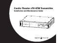
Cardio Theater xTV-9TM Transmitter
Installation and Maintenance Guide
Input
POWER
S ig n a l
xTV8TM Trans
mitter
T r a n s m it t e r
Channel
P rogram
®
Important Safety Guidelines
Always follow basic safety precautions when using this
equipment to reduce the chance of injury, fire, or damage.
Read all instructions in this guide before installing and using
the equipment. Follow any labels on the equipment.
•
Use the power adapter provided with the equipment. Plug the
power adapter into an appropriate, grounded power outlet as
marked on the equipment.
•
Route power cables so that they are not walked on or pinched
by items placed upon or against them.
•
Ensure that the equipment has adequate ventilation. Do not
place anything on top of or over the equipment. Do not use on
a cushioned surface that could block the ventilation openings.
•
Keep the equipment away from water and moisture.
•
Locate the equipment away from sources of heat, such as
radiators, heat registers, and stoves. Avoid temperature
extremes.
•
Avoid dropping anything on or spilling anything inside the
equipment, because doing so can damage the electronics.
•
Do not attempt to service the unit yourself except to follow the
maintenance instructions found in this guide.
CAUTION: DO NOT remove the cover, or you may risk
injury due to electric shock. Read the Installation and
Maintenance Guide before operating. There are no
user-servicable parts inside. Contact Customer
Support if the equipment needs servicing. For use with
single phase AC supply only.
Installation and Maintenance Guide: Important Safety Guidelines
PRECAUCIÓN: NO quite la cubierta, ya que podría
sufrir lesiones por descarga eléctrica. Antes de utilizar
la unidad, lea el Manual de instalación y mantenimiento.
No toque las piezas internas. Para cualquier tipo de
reparación, póngase en contacto con el Servicio de
atención al cliente. Utilícese únicamente con
alimentación de CA monofásica.
Safety Approval
When identified with the ETL-C logo, the unit has been tested and
conforms to the requirements of ANSI/UL 60950-1:2003 and
CAN/CSA C22.2 No. 60950-1-03 Information Technology
Equipment Safety, Part 1.
IMPORTANT SAFETY INSTRUCTIONS
•
AVERTISSEMENT : NE retirez PAS le capot de
l’appareil. Le retrait du capot expose l’utilisateur de
l’appareil à un risque de décharge électrique. Lisez le
guide d’installation et d’entretien avant toute utilisation.
Cet appareil ne contient aucune pièce réparable par
l’utilisateur. Contactez le service clientèle si une
réparation de votre équipement est nécessaire.
Utilisation avec alimentation alternative monophasée
uniquement.
1
Product Recycling and Disposal
This equipment must be recycled or discarded according to
applicable local and national regulations.
Product labels, in accordance with European Directive 2002/96/EC
concerning waste electrical and electronic equipment (WEEE),
determine the framework for the return and recycling of used
equipment as applicable throughout the European Union. The
WEEE label indicates that the product is not to be thrown away, but
rather reclaimed upon end of life per this Directive.
In accordance with the European WEEE Directive, electrical and
electronic equipment (EEE) is to be collected separately and to be
reused, recycled, or recovered at end of life. Users of EEE with the
WEEE label per Annex IV of the WEEE Directive must not dispose
of end of life EEE as unsorted municipal waste, but use the
collection framework available to customers for the return, recycling,
and recovery of WEEE. Customer participation is important to
minimize any potential effects of EEE on the environment and human
health due to the potential presence of hazardous substances in
EEE. For proper collection and treatment, refer to Obtaining
Service.
Regulatory Information
The Cardio Theater xTV-9TM Transmitter has been tested and found
to comply with the limits pursuant to Part 15 C of CFR 47, FCC
Rules. These limits are designed to provide reasonable protection
against harmful interference when operated in a residential
installation. This equipment generates, uses, and can radiate radio
frequency energy and, if not installed and used in accordance with
the owner’s manual instructions, may cause harmful interference to
radio communications.
FCC rules, changes or modifications not
WARNING Per
expressly approved by the manufacturer could
void the user’s authority to operate
the equipment.
Industry Canada Compliance Statement
This device complies with RSS-210 of the Spectrum Management &
Telecommunications Radio Standards Specification. Operation is
subject to the following two conditions: (1) this device may not
cause harmful interference, and (2) this device must accept any
interference received, including interference that may cause
undesired operation.
This device has been designed to operate with the antenna provided
having a maximum gain of 2.14 dbi gain. Antennas not included or
having a gain greater than 2.14 dbi are strictly prohibited for use
with this device. The required antenna impedance is 75 ohms.
FCC Compliance Statement
This device complies with Part 15 of the FCC Rules. Operation is
subject to the following two conditions: (1) this device may not
cause harmful interference, and (2) this device must accept any
interference received, including interference that may cause
undesired operation.
Installation and Maintenance Guide: Important Safety Guidelines
2
Table of Contents
Important Safety Guidelines .................................................1
Safety Approval ............................................................................... 1
Product Recycling and Disposal ................................................. 2
Regulatory Information .................................................................. 2
Before You Begin .....................................................................4
Obtaining Service ........................................................................... 4
Preparations ..............................................................................5
Unpacking the Equipment ............................................................ 5
Required Tools and Equipment ................................................... 5
Installation Requirements .............................................................. 6
Programming the Transmitter ............................................ 10
Connecting Audio to the Transmitter ............................... 11
Maintaining and Troubleshooting ..................................... 12
Cleaning the Transmitter .............................................................12
Adding or Replacing Channel Cards .......................................12
Troubleshooting the Transmitter ...............................................13
Limited Warranty .................................................................... 15
Installing the Transmitter .......................................................9
Installation and Maintenance Guide: Table of Contents
3
Before You Begin
With the Cardio Theater® xTV wireless system, fitness facilities can
add entertainment to exercise rooms without the high cabling costs
usually associated with entertainment systems. The xTV wireless
system gives people the choice of listening to music, radio, or
programs shown on TVs while they exercise. The person simply
plugs a stereo headphone into a receiver, selects the desired
entertainment, and exercises while listening to high-fidelity sound.
An xTV wireless system consists of one multi-channel xTV-9TM
Transmitter and a number of xTV900 Receivers installed on exercise
equipment throughout the room. The xTV-9TM Transmitter may
contain up to 12 channel cards, allowing facilities to connect up to
12 components to support a wide variety of entertainment options.
Preconfigured programming modes allow facilities to assign each
component its own frequency to ensure clear transmission while
avoiding any frequencies that may already be used in the area.
This guide explains how to install and maintain an xTV-9TM
Transmitter. For proper installation, please read this guide thoroughly
and follow the instructions.
Note: For information about the xTV900 Receivers, refer to the
xTV900 Receivers Installation and Maintenance Guide.
Installation and Maintenance Guide: Before You Begin
Obtaining Service
Do not attempt to service the xTV-9TM Transmitter except as
described in this guide. For information about product operation or
service, contact an authorized Cardio Theater Technical Support
Representative at 1-800-776-6695 or [email protected].
Representatives are available to serve you from 6:00 to 5:00 pm,
Monday through Friday, U.S.A. Pacific Time.
Returning Equipment to Cardio Theater
To return equipment to Cardio Theater for any reason, you must
contact Cardio Theater Technical Support and obtain a Return
Authorization Number (RMA). When requesting the RMA number,
explain why you are returning the equipment, for example you
ordered too many receivers and the extra receiver can be returned to
stock, or the equipment needs repairs.
Important: Equipment must be shipped with an RMA number in
order for Cardio Theater to process it. Any equipment received
without an RMA number will be returned to the sender.
4
Preparations
Remember to read and follow the instructions in this guide. If you do
not install the xTV-9TM Transmitter according to these instructions,
you could void the Limited Warranty.
Unpacking the Equipment
The transmitter is shipped with the following items:
• One xTV-9TM Transmitter with 4 channel cards standard: an
additional 8 channel cards may be installed for a total of 12 cards
• To connect transmitter to antenna, 25 feet (8 meters) RG-58 coax
cable with BNC connectors on both ends
• These installation instructions
If any items are missing, contact the dealer from whom you
purchased the equipment or contact Cardio Theater Technical
Support.
Note: For information about the xTV900 Receivers, refer to the
xTV900 Receivers Installation and Maintenance Guide.
Required Tools and Equipment
Obtain the following before installation:
• To connect audio components, RCA audio cable, one per
component
Input
POWER
S ig n a l
xTV8TM Trans
mitter
T r a n s m it t e r
Channel
• AC power cord
P rogram
• Phillips-head screwdriver
• Fastening hardware as appropriate to secure antenna assembly to
nearby wall
• Antenna assembly
Installation and Maintenance Guide: Preparations
5
Installation Requirements
Review the following requirements before installation:
• To ensure the best range and audio quality, select a location
without any major internal obstructions, such as metal support
posts, between the transmitter’s antenna and receivers installed
on the exercise equipment. The antenna and receivers should also
be installed so they are within 150 feet (50 meters) of each other
and are in direct line of sight.
• The xTV-9TM has four programming modes to support different
situations and countries. Each mode has different frequencies
assigned to its channels. Refer to the following tables to identify
the mode appropriate for your installation.
Table 1: Mode 1, U.S. LCS (Cardio), 52 channels
Channel
Frequency
Channel
Frequency
Channel
Frequency
1
905.40
19
909.80
37
919.00
2
907.40
20
912.00
38
921.00
3
909.00
21
913.00
39
922.80
• Cardio Theater recommends that you group audio components
together to minimize cabling. You can install the transmitter in a
rack with other audio components if desired.
4
910.40
22
913.80
40
924.40
7
914.20
25
• If the audio components are stacked in a cabinet, make sure the
equipment has adequate ventilation to avoid overheating.
8
915.40
26
9
916.20
27
924.40
45
903.60
• Install the antenna nearby so it is vertical. Do not install the
antenna so it is mounted horizontally, which will decrease its
transmission range. In addition, the antenna should not touch or
come near other transmitting antennas or metal objects. Be sure
to route cabling and power cords away from the antenna, so they
do not cause interference.
10
917.40
28
926.20
46
904.40
• You can mount the antenna up to 25 feet (8 meters) from the
transmitter. A coax cable (RG-58 or RG-8) connects the antenna
to the transmitter and eliminates any interference issues between
these two components. Using a higher quality (lower loss) cable
will allow a greater distance between the transmitter and antenna.
5
911.20
23
915.00
41
910.80
6
912.60
24
916.60
42
911.60
922.00
43
913.40
923.60
44
914.60
11
918.00
29
920.60
47
905.80
12
919.40
30
921.60
48
907.00
13
920.20
31
923.20
49
904.00
14
922.40
32
925.80
50
905.00
15
924.00
33
915.80
51
907.80
16
925.00
34
917.00
52
909.40
17
906.40
35
918.40
18
908.40
36
919.80
• Each audio component connected to the transmitter requires a
unique channel number. Channel numbers on a transmitter
determine frequencies. There is no correlation between channel
numbers on a transmitter and channel numbers shown on
receivers when they are programmed.
Installation and Maintenance Guide: Preparations
6
Table 2: Mode 3, xTV U.S., 32 channels
Table 3: Mode 2, Australia LCS (Cardio), 24 channels
Channel
Frequency
1
905.00
19
907.60
1
916.20
13
920.60
2
906.20
20
908.80
2
917.40
14
921.60
3
923.60
21
910.00
3
918.00
15
923.20
4
924.40
22
911.20
4
919.40
16
925.80
5
925.60
23
912.40
5
920.20
17
915.80
6
910.60
24
913.80
6
922.40
18
917.00
7
911.80
25
915.00
7
924.00
19
918.40
8
913.40
26
916.20
8
925.00
20
919.80
9
914.20
27
917.40
9
922.00
21
919.00
10
915.40
28
918.40
10
923.60
22
921.00
11
917.00
29
919.60
11
924.40
23
922.80
12
917.80
30
921.00
12
926.20
24
925.40
13
919.00
31
921.80
14
920.60
32
923.00
15
921.40
16
922.60
17
905.60
18
906.60
Channel
Frequency
Channel
Frequency
Channel
Frequency
Table 4: Mode 4, Australia xTV, 16 channels
Channel
Frequency
Channel
Frequency
1
923.60
9
922.60
2
924.40
10
916.20
3
925.60
11
917.40
4
917.00
12
918.40
5
917.80
13
919.60
6
919.00
14
921.00
7
920.60
15
921.80
8
921.40
16
923.00
• If you discover that some of the 900 MHz frequencies (see
Tables 1–4) are used by outside non-controllable sources, you
can set the transmitter to avoid those frequencies. However, this
will reduce the number of channels available for you to use when
installing transmitters. If the outside non-controllable source
generates a powerful signal, it may also cause static interference
with the wireless system, reducing audio quality.
Installation and Maintenance Guide: Preparations
7
• The transmitter uses Automatic Level Control (ALC) circuitry to
provide consistent sound levels to people using the receivers.
With this feature, once the sound level on TVs and other audio
components have been adjusted, the wireless system should not
experience sound fluctuations, which have been inherent in other
types of entertainment systems. To support this feature, the sound
level from the connected TV and audio components must be set to
a reasonable, median level. If the incoming sound level is set too
low, people may hear an excessive amount of background noise
while using the receivers. If the incoming sound level is set too
high, it may sound distorted through the receivers.
• To avoid confusion with people using the wireless system, you
want receivers to logically select TV and audio components based
on their placement. So, on the receiver, channel 1 would select the
first TV, channel 2 would select the second TV, and so on. To
support this logical usage, connect components to the transmitter
in channel order. The following explains how receivers assign
channels numerically.
The receiver automatically searches the area for active transmitter
channels and stores them in memory. It then assigns them to
channel numbers, starting with the lowest transmitting channel to
the highest transmitting channel, regardless of which channels are
used. For example, an installation has an xTV-9TM Transmitter with
assigned channel numbers 2, 4, 6, and 8; they are installed in that
order from left to right. The receiver has found these transmitted
channels and assigned them to a sequence of channel numbers
that it displays as 1 through 4. See Table 5.
Table 5: Sample installation with showing correct channel order
Transmitter Channels
(Installed in Channel
Order)
Receiver Assigns to Channel
Number that People Use to Select
Entertainment
1
2
1
3
4
2
5
6
3
7
8
Installation and Maintenance Guide: Preparations
4
8
Installing the Transmitter
1. Determine where you will install the transmitter and antenna.
An RG-58 or RG-8 coax cable connects the antenna to the
transmitter.
Junction
You can mount the antenna up to 25 feet (8 meters) from the
transmitter: using a higher quality (lower loss) cable will allow a
greater distance between the antenna and transmitter.
If possible, locate the antenna where its signals will have no
obstructions (such as metal support posts) to the receivers
installed on the exercise equipment. In addition, the distance
between receivers and antenna should not exceed 150 feet
(50 meters).
2. Place the transmitter where it will operate. Make sure that it is
located in a well-ventilated area with both the front and back
easily accessible. You can set the transmitter on a shelf or install
it in a rack with other components.
3. Install the antenna assembly in a vertical configuration. Typically,
the antenna assembly is installed on a wall near the transmitter.
The fastening hardware needed to install the assembly depends
on the wall, and must be provided by the installer.
Be sure to mount the antenna assembly away from sources that
will cause static interference, such as cables, other antennae,
and metal objects.
Antenna
assembly
Mounting bracket
Wall
4. Once the antenna assembly is mounted to the wall, adjust the
orientation of the antenna so it points toward the receivers. The
bracket can be rotated 180 degrees. Doing this helps to ensure
better transmission quality to the receivers.
5. After adjusting the orientation of the antenna, secure the bracket
placement by tightening the two screws in the bracket junction
with the Phillips-head screwdriver.
6. Connect the coax cable with the BNC connectors on both ends
to the antenna, and then connect it to the transmitter. Make sure
the placement of the coax cable does not cause a problem for
people or other equipment.
7. Plug the AC power cord, packaged with the transmitter, into the
back of the transmitter.
8. Plug the AC power cord into a nearby power outlet.
9. Clamp the provided ferrite filter onto the antenna coax cable in
close proximity to the transmitter.
Installation and Maintenance Guide: Installing the Transmitter
9
Programming the Transmitter
1. Determine the channel number you want to assign to each card
in the transmitter. Each card requires a unique channel number.
Assign channels in sequential order to make the wireless system
easier to use. See Table 6.
Note: Table 6 provides blank columns that installing technicians
can use to note setup information. Consider providing a brief
description of what entertainment each transmitter channel
provides (or is connected to) and indicate the associated
receiver channel that gets assigned.
Different channel numbers will provide better reception based on
whether or not other equipment in the facility are using the same
frequency, or possible influences from the facility infrastructure.
During installation, you may need to change the channel number
based on the sound quality captured by the receivers.
Table 6: Site with up to 8 components
Transmitter
Channel
1
2
3
4
5
6
7
8
9
10
11
12
Description of Channel
(Write a brief description
for your site)
Receiver
Channel
Installation and Maintenance Guide: Programming the Transmitter
2. Enter the appropriate programming mode by pressing and
holding the correct key while you turn on the transmitter. The key
determines in which mode you start up the transmitter. The
transmitter displays a set of numbers to confirm the mode you
have selected.
To start up
Then, press and hold
Transmitter displays
U.S. LCS (Cardio)
52 channels (Mode 1)
Transmitter UP
1776
U.S. xTV 32 channels
(Mode 3)
Channel UP
0776
Australian LCS (Cardio)
24 channels (Mode 2)
Transmitter DOWN
1901
Australian xTV 16 channels
(Mode 4)
Channel DOWN
0901
3. Set the channel number on each card. Use the Transmitter ▲
and ▼ keys to select a card; use the Channel ▲ and ▼ keys to
specify the channel number.
The first two numbers on the display indicates the selected card,
for example “06:07” indicates card 6. The second two numbers
indicate the channel. In the example, “07” indicates channel 7.
4. When you have selected the channels for all of your cards, press
the PROGRAM button to lock in your selections. The display
stops blinking, the transmitter reboots, and then it returns to
normal operation.
10
Connecting Audio to the Transmitter
1. Connect one end of the RCA audio cable to the TV or audio
source. Observe and follow the color code of the RCA audio
cable connectors. If available, connect the RCA cable to the Line
Audio Output connector on the TV or audio source.
The Line Audio Output connector is recommended because it
always provides a consistent sound level and cannot be modified
by users.
2. Connect the other end of the RCA audio cable to the transmitter.
Observe and follow the color code of the RCA audio cable
connectors.
6. Make sure the sound levels provided by the transmitter are
consistent across all channels. Plug headphones into a wireless
receiver, then move through the channels, listening to the sound
level and checking for disturbing or noticeable differences as you
switch channels. If necessary, match the sound level provided by
each TV and audio component by making slight adjustments to
that component’s volume.
7. If desired, place numbered signs by each TV or audio
component. People will use the number on each sign to select
the desired entertainment.
Important: Make sure the RCA cable is not near the power
cable, or it could interfere with the audio signal.
3. If connecting to a TV, turn off its speakers using the appropriate
menu function.
4. Continue connecting audio components to the transmitter
following the instructions in steps 1 to 3 for each component.
5. When all the components are connected to the transmitter,
check the sound quality from the transmitter using the receivers
at each piece of exercise equipment around the room.
If you find that a specific channel is not received well anywhere in
the room, try changing the transmitter to a different channel. You
may need to try several channels to improve sound quality. Some
channels will be received better than others in a facility due to the
infrastructure and radio frequency activity in the area. If you need
to change the channel on a transmitter to improve sound quality,
you will need to reprogram the receivers.
Installation and Maintenance Guide: Connecting Audio to the Transmitter
11
Maintaining and Troubleshooting
In general, the xTV-9TM Transmitter requires little maintenance.
Refer to Cleaning the Transmitter for information.
Adding or Replacing Channel Cards
Over time, you may find that you want to add one or more audio
components to the transmitter. Each additional audio component will
need its own channel card. The xTV-9TM Transmitter can have up to
12 channel cards installed, supporting up to 12 audio components.
You may also find you need to replace an existing channel card when
it no longer functions correctly. This section explains how to add or
replace channel cards as needed.
You will need the following tools:
Problems with the transmitter typically occur during installation.
Otherwise, you should experience few problems once the
transmitter is installed correctly. If needed, you may find the
troubleshooting information in this section useful for solving any
problems you experience.
To add or replace a channel card you will need to open the
transmitter and move the motherboard. You can then add or replace
one or more channel cards as needed.
• Phillips-head screwdrivers, various sizes
Important: Before beginning the procedure, place the transmitter
on a table with space to work, located in an ESD-approved
environmentally controlled work area. And ESD grounding
wristband must be worn at all times while working on the
transmitter with the cover removed.
1. Make sure the power cord is unplugged.
2. Remove the screws holding the currently installed cards to the
rear of the case.
Cleaning the Transmitter
Periodically dust the transmitter with a soft dry cloth.
3. Remove the nut and star washer holding the BNC connector to
the rear of the case.
Important: Do not use liquid cleaners or aerosol cleaners to clean
the equipment. Do not use any solvents such as alcohol and paint
thinner.
CAUTION: Make sure you take appropriate anti-static
precautions for the following steps. If the electronics of the
transmitter are damaged, you could void the Limited Warranty.
4. Remove the top cover from the transmitter. Use a Phillips-head
screwdriver to remove the 12 screws holding the top cover.
5. Inside the transmitter, remove the 8 screws holding the
motherboard to the case. One screw also attaches the ground
cable to the motherboard.
6. Gently slide the motherboard toward the front of the case until
the BNC connector and audio connectors on the channel cards
are free from the rear of the case.
Installation and Maintenance Guide: Maintaining and Troubleshooting
12
7. If you plan to replace a card, gently remove that card.
8. If you plan to add one or more cards, remove the jumpers for the
slots where you plan to install additional cards (see the existing
card configuration for reference as needed).
9. If you plan to add one or more cards, remove the plugs
associated with each slot that will be used.
10. Install the new channel card(s) into the appropriate slot(s). Make
sure that the connector is fully seated.
11. Carefully slide the motherboard toward the rear of the case,
fitting the BNC connector and audio connectors on the channel
cards through the holes in the rear of the case.
12. Make sure the holes in the motherboard are aligned with the
screw holes below, then re-install the 8 screws holding the
motherboard. Be sure to re-connect the ground cable with the
appropriate screw.
13. Re-install the star washer and nut holding the BNC connector to
the rear of the case.
14. Insert the screws holding the channel cards to the rear of the
case. Screws for new channel cards come with the card.
15. Re-install the cover with the 12 screws removed earlier.
16. Program the new channel card(s) as needed following the
instructions earlier in Programming the Transmitter.
Troubleshooting the Transmitter
Table 7 may help you to understand and troubleshoot any problems
that you encounter with the xTV-9TM Transmitter. If the suggestions
in the table do not help you solve the problems that you encounter,
contact Cardio Theater Technical Support.
Installation and Maintenance Guide: Maintaining and Troubleshooting
Table 7: How to solve most problems with transmitters
Problem
Static
interference
What to Do
Single
receiver
Most likely problem with receiver; see Maintenance
and Troubleshooting in receiver guide.
All
receivers
• Sound level on TV or audio component may be too
high. Check the equipment and adjust the sound
level as needed.
• Check to see if any outside sources are using the
same frequency as the transmitter. Either locate and
remove the outside interference, or change the card
to a different channel to avoid that frequency.
• Check the coax cable between the transmitter and
antenna. Check the BNC connectors on the cable.
• Make sure the correct mode and channel number
are specified on the transmitter for that audio
component.
• Check the sound from audio component by
connecting it to a different transmitter channel card.
Listen from a receiver to see if the sound improves.
• Check the transmitter channel card by connecting a
working audio component to the suspect channel
card. Listen from a receiver to see if the sound
returns on the suspect channel card. If it returns, the
problem may be with the audio component. If the
sound continues poorly or not at all, then the
transmitter channel card may need to be serviced.
• Make sure the transmitter has power by checking
the AC power cord: Is it plugged into a nearby outlet
and into the transmitter?
• Make sure that the antenna is upright and not
located near a power cord, audio cable, or any metal
objects.
• If the problem continues, unplug the power cord for
five minutes, then plug back in.
13
Problem
Noisy
sound
Single
receiver
What to Do
Problem
• Make sure there are no major internal obstructions,
such as metal support posts, between antenna and
receiver.
No sound
What to Do
Single
receiver
• Otherwise, most likely problem with receiver; see
Maintenance and Troubleshooting in receiver guide.
All
receivers
• Make sure the antenna and receivers are installed so
they are within 150 feet (50 meters) of each other.
• Make sure that the antenna is upright and not
located near a power cord, audio cable, or any metal
objects.
• Otherwise, most likely problem with receiver;
see Maintenance and Troubleshooting in
receiver guide.
All
receivers
• Sound on the TV or audio component may be too
low or muted. Check the equipment and increase
the sound or unmute as needed.
• Check the sound from audio component by
connecting it to a different transmitter channel card.
Listen from a receiver to see if the sound improves.
• Make sure the sound level of the TV or audio
component connected to the transmitter is set to a
reasonable, median level.
• Check the transmitter channel card by connecting a
working audio component to the suspect channel
card. Listen from a receiver to see if the sound
returns on the suspect channel card. If it returns, the
problem may be with the audio component. If the
sound continues poorly or not at all, then the
transmitter channel card may need to be serviced.
• Try changing the transmitter to a different channel to
see if the sound quality improves. Some channels
will be received better than others.
• Make sure no other wireless transmitters are using
the same channel (and frequency) at the facility. If
other types of transmitters are installed, you should
call Technical Support for help with determining the
frequencies being used. If necessary, change the
channel number on the errant transmitter.
• Make sure the transmitter has power by checking
the AC power cord: Is it plugged into a nearby outlet
and into the transmitter?
• Make sure the card to which the audio component is
connected to has a channel number assigned. The
card may not have been set up with a channel. A
card can also be deselected by specifying “no
channel.”
• Check to see if any outside sources are using the
same frequency as the transmitter. Either locate and
remove the outside interference, or change the
transmitter to a different channel to avoid that
frequency.
Receiver channels do
not match the order of
the TV and audio
components;
for example, channel 1
selects the second TV
and channel 2 selects
the first TV.
Installation and Maintenance Guide: Maintaining and Troubleshooting
• Make sure there are no major internal obstructions,
such as metal support posts, between antenna and
receiver.
• Audio components were not installed in channel
order. Receivers automatically assign transmitter
channels to receiver channels, from lowest to
highest (see Table 5). Move or reprogram the
transmitter so channel numbers are in a logical
sequence. You will need to reprogram receivers.
14
Limited Warranty
PLEASE READ THESE WARRANTY TERMS AND CONDITIONS CAREFULLY BEFORE
USING YOUR CARDIO THEATER PRODUCT. BY USING THE EQUIPMENT, YOU ARE
CONSENTING TO BE BOUND BY THE FOLLOWING WARRANTY TERMS AND
CONDITIONS.
Limited Warranty.
Precor Incorporated (“Precor”) warrants all new Cardio Theater products to be free from
defects in materials and manufacture for the warranty periods set forth below. The warranty
periods commence on the invoice date of the original purchase. This warranty applies only
against defects discovered within the warranty period and extends only to the original
purchaser of the product. Parts repaired or replaced under the terms of this warranty will be
warranted for the remainder of the original warranty period only. To claim under this
warranty, the buyer must notify Precor or your authorized Cardio Theater dealer within 30
days after the date of discovery of any nonconformity and make the affected product
available for inspection by Precor or its service representative. Cardio Theater product
deemed defective by a Cardio Theater representative, will be issued a return authorization
number. Precor will not accept returns without a return authorization number. Precor
reserves the right, at their option, to repair or replace the product after verification of defect.
Product that fails after the warranty period expires will be repaired or replaced at the current
part and labor pricing after authorization from the customer. Repairs are warranted for 90
days.
Precor’s obligations under this warranty are limited as set forth below.
Warranty Periods and Coverage.
• Cardio Theater Transmitters
xTV-T Wireless or Wired Floor Models
xTVFM system transmitter
• Cardio Theater Receivers
XTV-R Wireless or Wired Upper Models
XTVFM system receiver
• Cardio Theater LCD Screen (PVS)
• Cardio Theater Screen Controllers
• Quick Change Headphone Jack
• Optional DVD Player
• CT Experience Series Screen (PVS12)
• CT Experience Series Screen Controller
• CT Experience Series 900 & 863 Receiver
• CT Experience Series Quick Change
Headphone Jack
3 Years
Parts & Labor
1 Year
Parts & Labor
1 Year
1 Year
90 Day
1 Year
2 Years
2 Years
2 Years
90 Days
Parts & Labor
Parts & Labor
Parts Only
Parts
Parts & Labor
Parts & Labor
Parts & Labor
Parts Only
Installation and Maintenance Guide: Limited Warranty
Conditions and Restrictions.
This warranty is valid only in accordance with the conditions set forth below:
1. The warranty applies to the Cardio Theater product only while
a. it remains in the possession of the original purchaser and proof of purchase is
demonstrated,
b. it has not been subjected to accident, misuse, abuse, improper service, or
mechanical, electrical or non-Precor modification.
c. claims are made within the warranty period.
2. This warranty does not cover damage or product failure caused by electrical wiring not
in compliance with electrical codes or Precor owner’s manual specifications, or failure to
provide reasonable and necessary maintenance as outlined in the owner’s manual.
This warranty excludes misuse or failures of, for example, poor quality CD’s,
multiple discs inserted in the player, failures caused by home-produced copies
of discs, etc.
3. Except in Canada, Precor does not pay labor outside the United States.
4. Warranties outside the United States and Canada may vary. Please contact your local
Dealer for details.
This Limited Warranty shall not apply to:
1. Software (PROM) version upgrades.
2. Normal wear and tear, consumables and cosmetic items, including, but not limited to
the following: labels.
3. Repairs performed on Cardio Theater products missing a serial number or with a serial
tag that has been altered or defaced.
4. Service calls to correct installation of the product or instruct owners on how to use
the product.
5. Pickup and delivery involved with repairs.
6. Any labor costs incurred beyond the applicable labor warranty period.
7. The user is cautioned that changes or modifications not expressly approved by the
manufacturer of the product could void the user’s authority to operate the product.
15
Disclaimer and Release.
The warranties provided herein are the exclusive warranties given by Precor and supersede
any prior, contrary or additional representations, whether oral or written. ANY IMPLIED
WARRANTIES, INCLUDING THE WARRANTY OF MERCHANTABILITY OR FITNESS
FOR A PARTICULAR PURPOSE THAT APPLY TO ANY PARTS DESCRIBED ABOVE
ARE LIMITED IN DURATION TO THE PERIODS OF EXPRESS WARRANTIES GIVEN
ABOVE FOR THOSE SAME PARTS. PRECOR HEREBY DISCLAIMS AND EXCLUDES
THOSE WARRANTIES THEREAFTER. Some States do not allow limitations on how long
an implied warranty lasts, so the above limitation may not apply to you. PRECOR ALSO
HEREBY DISCLAIMS AND EXCLUDES ALL OTHER OBLIGATIONS OR LIABILITIES,
EXPRESS OR IMPLIED, ARISING BY LAW OR OTHERWISE, WITH RESPECT TO ANY
NONCONFORMANCE OR DEFECT IN ANY PRODUCT, INCLUDING BUT NOT LIMITED
TO: (A) ANY OBLIGATION, LIABILITY, RIGHT, CLAIM OR REMEDY IN TORT, WHETHER
OR NOT ARISING FROM THE NEGLIGENCE OF PRECOR OR ITS SUPPLIERS
(WHETHER ACTIVE, PASSIVE OR IMPUTED); AND (B) ANY OBLIGATION, LIABILITY,
RIGHT, CLAIM OR REMEDY FOR LOSS OF OR DAMAGE TO ANY PRODUCT. This
disclaimer and release shall apply even if the express warranty set forth above fails of its
essential purpose.
Exclusive Remedies.
For any product described above that fails to conform to its warranty, Precor will provide, at
their option, one of the following: (1) repair; (2) replacement; or (3) refund of the purchase
price. Limited Warranty service may be obtained by contacting the authorized dealer from
whom you purchased the item. Precor compensates Servicers for warranty trips within their
normal service area to repair commercial product at the customer’s location. You may be
charged a trip charge outside the service area. THESE SHALL BE THE SOLE AND
EXCLUSIVE REMEDIES OF THE BUYER FOR ANY BREACH OF WARRANTY.
EXCLUSION OF CONSEQUENTIAL AND INCIDENTAL
DAMAGES.
PRECOR AND/OR ITS SUPPLIERS SHALL HAVE NO OBLIGATION OR LIABILITY,
WHETHER ARISING IN CONTRACT (INCLUDING WARRANTY), TORT (INCLUDING
ACTIVE, PASSIVE, OR IMPUTED NEGLIGENCE AND STRICT LIABILITY), OR
OTHERWISE, FOR DAMAGE TO THE PRODUCT, PROPERTY DAMAGE, LOSS OF
USE, REVENUE OR PROFIT, COST OF CAPITAL, COST OF SUBSTITUTE PRODUCT,
ADDITIONAL COSTS INCURRED BY BUYER (BY WAY OF CORRECTION OR
OTHERWISE) OR ANY OTHER INCIDENTAL, SPECIAL, INDIRECT, OR
CONSEQUENTIAL DAMAGES, WHETHER RESULTING FROM NONDELIVERY OR
FROM THE USE, MISUSE OR INABILITY TO USE THE PRODUCT. This exclusion applies
even if the above warranty fails of its essential purposes and regardless of whether such
damages are sought for breach of warranty, breach of contract, negligence, or strict liability
in tort or under any other legal theory. Some states do not allow the exclusion or limitation of
incidental or consequential damages, so the above limitation may not apply to you.
This warranty gives you specific legal rights, and you may also have other rights, which vary
from state to state.
Complete this portion and keep for your records.
Purchased From: _____________________________________________________
(Dealer or store name)
Phone Number:
_____________________________________________________
(Dealer or store telephone number)
Product/Model:
_____________________________________________________
(For example: Transmitters, Receivers)
Serial Number:
_____________________________________________________
(The serial number is found on the shipping container or item.)
Effective 30 June 2006
P/N CX30037-102
Installation and Maintenance Guide: Limited Warranty
16
®
Cardio Theater is a registered trademark, and Cardio Theater PVS and Cardio Theater Quick Change
Headphone Jack are trademarks of Precor Incorporated.
www.cardiotheater.com
A Division of Precor Incorporated
20031 142nd Ave NE
Woodinville, WA USA 98072-4002
NOTICE:
Due to continuing advancements in technology, Precor Incorporated reserves the right to make changes in
hardware, packaging, and any accompanying documentation without prior written notice.
xTV-9TM IMG CX30422-105
Warranty Statement CX30037-102
25 March 2008