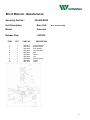
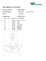
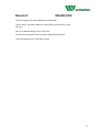
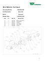
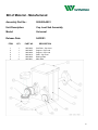
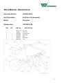
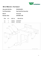
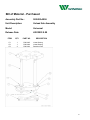
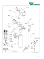
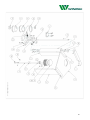
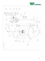
1
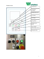
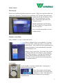
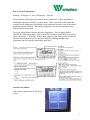
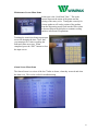
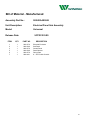
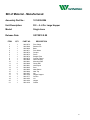
Model101
Rot
aryI
ndexPackagi
ngMachi
ne
Mach.No.W101101
Table of Contents
Main Bill of Materials………………………………………..…...………..3
Machine Control Operation……………………………………...………..5
Base Unit…………………………………………………………...……...15
Cup Place Station…………………………………………….…...………40
Fill Station…………………………………………………………...…….47
Foil Place Station..………………………………………………...………51
Heat Seal Station…………………………………………..……...………55
Unload Station…………………………………………………….....……59
Air Electrical………………………………………………………………63
Tooling Package…………………………………………………………...66
Perimeter Guarding……………………………………………………....68
Gearing and Lubrication..………………………………………...……...72
Appendix A - Electrical…………………………………………...……....73
Appendix B -Camco Indexer……………………………..………………78
Warranty and Parts………………………………………..…...……….101
2
Bill of Material - Manufactured
Assembly Part No.:
101-119-2950
Unit Description:
Machine - Complete
Model:
Single Lane - Small, Liquid Fill
Release Date:
8/4/2009 0:00
ITEM
QTY.
PART NO.
DESCRIPTION
1
1
000-000-0002
Machine Base
B.O.M.
2
1
101-001-0006
Station 01Cup Load
B.O.M.
3
1
101-002-0006
Station 02 Fill
B.O.M.
4
1
101-004-0001
Station 04 Foil Place
B.O.M.
5
1
101-005-0004
Station 05 Seal
B.O.M.
6
1
101-006-0001-A
Station 06 Unload
B.O.M.
7
1
101-008-0005
Electric/Pnuematic Package
B.O.M.
8
1
101-009-2950
Tooling Pack
B.O.M.
9
1
000-010-0006-A
Perimeter Guard
B.O.M.
3
4
Machine Control
Touch Screen
Temperature
Controller
Machine Power On
Cycle Start
Cycle Stop
E-Stop Reset
Machine Cycle
Speed
Zone On/OFF
(filler/foil place/heater)
Emergency Stop
5
Main Controls:
Powering Up:
Ensure lower guards and perimeter guards are in place. Plug power into the machine and
connect the air pressure. Turn the power switch to the “ON” position. The touch screen
should come on and will indicate "Power
Off." Now press the green "E-Stop
Reset" button on the panel above the
"Emergency Stop."
Indicator should now read “Powering
Up” and “E-Stop Reset” button should
now be lit up green.
Next, verify that the machine is in Auto
or Manual Mode.
Manual vs. Auto Mode:
Select “Manual” or “Auto” on the touch screen.
When in “Manual” mode, press and hold “Cycle Start”
to cycle the table. When you release “Cycle Start” the
table will stop. This is useful for slowly positioning and
timing the machine, or for troubleshooting a particular
process during a cycle.
When in “Auto” mode, press “Cycle Start” once to start
cycling the table and “Cycle Stop” to stop cycling the
table. When you press “Cycle Stop” the machine will
continue briefly until the heater head rises off of the
table. This is to prevent the heater head staying down
on a container and seal.
Cycle Speed:
Set the Machine Cycle Speed with the dial. Actual speed is
indicated on the touch screen.
Note: This number will not change
unless the machine is in motion either
“Manual” or “Auto.” This indicator is
a measured cycle rate and the machine must be running to
measure the rate.
6
Optimum cycle speed is determined by a variety of factors. During run-off you should
have been given optimum cycle speeds. However, a good rule of thumb is, the faster the
machine, the higher the temperature and/or the greater the pressure needed for quality
seals. Speed may also be dictated by the filling process. Optimum settings for various
products and various container styles may be stored in the Recipe menu of the touch
screen HMI.
Note: Recipes stored do not change the machine, they are for reference only.
Operating the Machine:
Load cups into the cup drop station. Ensure that the cup drop cams are adjusted to
release a cup immediately after the cup pocket on the dial plate stops under the cup drop.
If the cup drops too late the sensor underneath will not have read that there is a cup and
as such the filler will not be signaled to perform, and the foil will not be placed on the
container. For more information on adjusting the cup drop cams see the section on the
cup load 101-001-0006.
Place foils into the machine. Remember to place foils into the machine upside down as
they will be rotated down onto the container.
Turn the “Zone 1 ON/OFF” to the ON position. This will enable the filler to perform, it
will enable the foil place to perform and will turn on the temperature
controller.
You will immediately get a fault showing on the touch screen for
“Zone 1 Temp fault.” The temperature controller is factory set to send
an alarm when it is 35 or more Degrees above or below the target
temperature.
Wait for the temperature to reach the target
and then hit the “Fault Reset” button on the touch screen.
The optimum temperature setting should have been given to
you during run-off. Generally speaking the cup and seal manufacturers will have the
specs for sealing the containers, but this may also vary on operating conditions and cycle
speed.
7
How to set the Temperature:
Example: 80 Degrees = F 80 or 200 Degrees = F200 etc.
The two buttons on the right of the display set the temperature. If the temperature is
flashing then the heater control is in tuning mode. There is an alarm on the heater that
when the actual temperature falls outside a given range then it sends a fault to the control
panel that stops the machine. Wait for the temperature to come back up and reset the
fault and restart the machine.
The green digital display indicates the target temperature. The red digital display
indicates the actual temperature. It takes about 20-30 minutes for the heater to reach the
preset temperature. CAUTION: It takes about 2 hours for the heater to cool off after the
machine has been shut down. The faster the machine is running the higher the
temperature that you want for consistently good seals.
Touch Screen Menus:
There are four main menus on the touch
screen.
8
Manual Screen Menu Items:
You may only use the “Manual Screen” options, if the machine is “In Manual Mode” If
the machine is “In Auto Mode” they will have no effect.
Prime/ Purge: If you have a Wilpack Packaging factory installed filler,
this will turn the rotary valve, actuate the piston to dispense product,
turn the rotary valve again and return the piston thereby drawing
product up to be dispensed on the next cycle. This is useful for
initially priming the filler for the first run or for purging the filler after
a run is complete. This is also useful for testing and adjusting fill
volume.
“Filler Ret’d” and “Adv. Filler”:
“Filler Ret’d” puts the piston in the position
where product is waiting to be dispensed.
“Adv. Filler” puts the piston in the position
where product has been dispensed and is ready
to draw product back into the tube from the
hopper/source.
“Rot. At Fill” and “Rot. To Dispense”:
“Rot. At Fill” positions the rotary valve so that product can be drawn up into the tube for
dispensing.
“Rot. To Dispense” positions the rotary valve so that product can be dispensed.
Foil Place Menu Items:
“Turn Vac. On” and “Turn Vac. Off” toggle the vacuum for the foil
place station.
To go back to the Main Screen touch the
button that indicates so.
9
Maintenance Screen Menu Items
In this area is the “Suck Back Time.” This is the
interval between the return of the piston and the
closing of the rotary valve. Timing this correctly for
viscous products will suck a portion of the product
from the dispensing nozzle back into the filler so that
it does not drip on the dial plate or container sealing
surfaces in between fill operations.
Touching the actual time brings up an input
screen for changing the time. Note: that
you cannot put in a value exceeding the
indicated values on screen. When
completed, press the “ENT” button to close
the input screen.
Alarm Screen Menu Items
The Alarm Screen is a review of the last 7 faults or alarms, when they occurred and what
the alarm was. This can be useful for troubleshooting.
10
Recipe Screen Menu Items
* Note: the flashing red text reads…”changing a recipe has no effect on the machine”
This area is for reference only.
There is room for up to 10 recipes.
Use “Prev Recipe” and “Next Recipe” to toggle between recipes. If you
touch a recipe category name, an input screen will appear to change the
name of that category. If you touch a recipe value, an input screen will
appear to change the value of the category.
11
Machine Operation Basics
Home Position:
Proximity Sensor
Cam Arm
If looking at the underside of the machine from the eject side, look for the Cam Arm and
the proximity sensor located nearby. When the arm is back far enough to interact with the
proximity sensor (the sensor will be lit up) then the machine is in “Home Position.”
Cup drop Sensor
In “Home Position” the machine is
looking for a cup with the cup drop
sensor located just under the dial
plate where the cup drops.
If the machine does not detect a cup
in place while the machine is in
“Home Position” then the for the
next 6 cycles the machine logic will
always assume there is not cup in
that index, and as such will not tell
the filler to perform, and will not
place a foil. Adjust the cup drop to
ensure a cup falls into the pocket
just as the table stops moving and it should be read when the machine reaches “Home
Position”
“Home Position” also tells the foil place station to turn the vacuum on for the next foil.
However if there was no cup detected in the pocket that is currently one index away from
12
the foil place station, then the logic will override this and not allow the foil to be picked
up. There is no sense placing a foil if there is no cup.
Foil Place Proximity Sensor:
If looking at the underside of the machine from the foil place and heat seal side of the
machine you should see a proximity sensor that interacts with the foil place shaft.
Foil Place Shaft
Proximity Sensor
When the foil place shaft moves down and triggers the Proximity Sensor then that tells
the vacuum holding the foil to turn off, thereby dispensing the foil onto the container. If
there is another cup in the next index then the vacuum will turn back on when the “Home
Position” is reached.
13
Foil Place and Table Detent Airflow Sensors
Table Detent Airflow Sensor
(The larger of the two)
Foil Place
Airflow Sensor
(The smaller of
the two)
The foil place sensor detects airflow when there is a vacuum created and holding a foil.
If air is flowing then it indicates a foil was not picked up (maybe the stack was empty) or
a foil fell off before the vacuum was shut off (maybe the vacuum was too weak).
Regardless, if there is supposed to be a vacuum and there is airflow it will create a fault.
Determine the cause and reset the fault on the HMI prior to cycling the machine again.
The Table Detent sensor measures airflow coming up through the support of the dial
plate. There is constant air pressure on the table. If the table comes out of detent, then
air flows and this triggers a fault that immediately shuts the machine off. This is to
prevent the machine from jamming and an additional safety feature. If the table comes
out of detent rotate it back into detent. There is only one position that the table can be in
and you should be able to feel it go back into detent. You may need to wiggle it into
position. Once this is done, reset the fault on the HMI before cycling the machine again.
14
Bill of Material - Manufactured
Assembly Part No.:
000-000-0002
Unit Description:
Base Unit
Model:
Universal
Release Date:
10/1/2009 0:00
ITEM
QTY.
PART NO.
1
2
3
4
5
6
7
8
1
1
1
1
1
1
1
1
000-000-A000-A
000-000-B000
000-000-C000
000-000-A001
000-000-A004
000-000-A005
000-000-A006
000-000-A008-B
DESCRIPTION
Base Sub-Ass'y.
Drive Sub-Ass'y.
Cam Sub-Ass'y.
Cup Load Sub-Ass'y.
Foil Place Sub-Ass'y.
Seal Sub-Ass'y.
Unload Sub-Ass'y.
Electrical Panel Sub-Ass'y.
B.O.M.
B.O.M.
B.O.M.
B.O.M.
B.O.M.
B.O.M.
B.O.M.
B.O.M.
15
16
Base Unit
000-000-A000-A
The Base Unit consists of 4 legs and the frame with base and top units.
The three stainless steel sides are held on with the P4 detents and the two sides
#14 are held in place with a bolt. Notice that Item 10 (Qty 2), is the last piece to
be fitted over the other two sides.
17
Bill of Material - Manufactured
Assembly Part No.:
000-000-A000-A
Unit Description:
Base Unit
Model:
Universal
Release Date:
8/31/2009 0:00
ITEM
QTY.
PART NO.
1
2
3
4
5
6
7
8
9
10
11
12
13
14
1
1
1
1
1
1
1
2
1
1
1
1
1
2
000-0001
000-0396
000-0397
000-0418
000-0419
000-0513
000-1531
000-1532
000-1533
000-1534
000-1536
000-1537
000-1538
000-1539
DESCRIPTION
Dial Plate Blank
Leg
Leg
Upper Splash Guard
Lower Splash Guard
Rear Cover
Front Panel
Bracket
Leg
Leg
Base Plate
Top Plate
Top Cover
Side Cover
18
Bill of Material - Purchased
Assembly Part No.:
000-000-A000-A
Unit Description:
Base Unit
Model:
Universal
Release Date:
8/31/2009 0:00
ITEM
QTY.
PART NO.
P1
P2
P3
6
4
2
P00-0036
P00-0071
P00-0072
DESCRIPTION
Spring Stop
Leg
Threaded Insert
19
Base Unit
000-000-B000
Drive Sub Assembly
The Camco Drive unit and Baldor Motor are the central drive units of the
machine.
The center shaft protruding up-wards from the motor is fitted with a air seal.
Should the dial be broken loose from its home position, the detents, P7,
disengage, and the air pressure switch (not-shown) senses the loss of pressure.
This pressure switch (not-shown) can only be reset in the home position. Again,
this is a single position on the dial. Rotate the dial until the home position is
achieved and the air sensor will de-activate. Press the Green Start button on
the Control Panel to re-start machine.
Also, Item 3, houses the sensor for the release of the foil from the sucker cup on
the foil place station.
Item P5, shows the sensor for the home position of the machine.
20
Bill of Material - Manufactured
Assembly Part No.:
000-000-B000
Unit Description:
Base Unit
Model:
Universal
Release Date:
04/22/03
ITEM
QTY.
PART NO.
1
2
3
4
5
6
7
8
9
10
1
1
2
1
1
1
1
1
1
1
000-0417
000-0604
000-0656
000-0959
000-0960
000-0961
000-0962
000-0963
000-0982
000-1554
Drive Sub Assembly
DESCRIPTION
Indexer Support
Bracket Mount
Prox. Bracket
Dial Plate Riser
Hub
Detent
Cap
Retaining Ring
Indexer
Gaslet
21
Bill of Material - Purchased
Assembly Part No.:
000-000-B000
Unit Description:
Base Unit
Model:
Universal
Release Date:
Drive Sub Assembly
4/22/2003 0:00
ITEM
QTY.
PART NO.
DESCRIPTION
P1
PA
P3
P4
P5
P6
P7
P8
P9
P10
P11
1
1
1
1
2
1
3
1
1
1
1
P00-0001
P00-0012
P00-0016
P00-0018
P00-0037
P00-0038
P00-0039
P00-0050
P00-0051
P00-0052
P04-0009
Motor - 1/2 HP 56C Frame
Indexer
Chain
Sprocket
Proximity Sensor
Chain Connector
Spring Plunger
Pipe Coupling
Pipe Nipple
Pressure Switch
Rotary Elbow
22
Base Unit
000-000-C000
This is the lifting unit for the completed part unload station.
The P5, sensor, (as noted in Base Unit, Camco Drive) reads at Item 6, on the
cam arm.
Item 10, is attached directly to the Camco Drive.
Grease zirks are located on two (2) of the P1 (Pillow Block) locations.
Clean and lubricate Item 5, Cam Paths, weekly.
23
Bill of Material - Manufactured
Assembly Part No.:
000-000-C000
Unit Description:
Base Unit
Model:
Universal
Release Date:
04/22/03
ITEM
QTY.
PART NO.
1
2
3
4
5
6
7
8
9
10
1
1
1
1
1
1
1
1
1
1
000-0403
000-0407
000-0408
000-0427
000-0428
000-0429
000-0430
000-0440
000-0939
000-1008
DESCRIPTION
Sub Plate
Support
Support
Drive Shaft
Cam - Compound
Cam Arm
Pivot Block
Pivot Pin
Drive Hub
Coupler
24
Bill of Material - Purchased
Assembly Part No.:
000-000-C000
Unit Description:
Base Unit
Model:
Universal
Release Date:
4/22/2003 0:00
ITEM
QTY.
PART NO.
P1
P2
PA
P4
P5
PA
2
2
1
1
1
1
P00-0003
P00-0005
P00-0017
P00-0019
P00-0020
P00-0029
DESCRIPTION
Bearing - 4 Bolt Flange
Flange Bearing
Coupling
Cam Follower
Cam Follower
Core Pin
25
Cup Load Sub Assembly
000-000-A001
The Cup Load Station is driven by this unit. The chain that is attached to the
Camco Drive powers this station.
The chain has an idler, P5, for take up of slack.
Grease zirks are located at P4, and each of the four (4) P1 (Pillow Block),
locations.
26
Bill of Material - Manufactured
Assembly Part No.:
000-000-A001
Unit Description:
Cup Load Sub Assembly
Model:
Universal
Release Date:
04/22/03
ITEM
QTY.
PART NO.
1
2
3
4
5
6
1
1
1
1
1
2
000-0402
000-0405
000-0406
000-0416
000-0600
000-0921
DESCRIPTION
Sub Plate - Cup Load
Support - Cup Load
Support - Cup Load
Shaft - Cup Load
Bearing Plate
Miter Gear
27
Bill of Material - Purchased
Assembly Part No.:
000-000-A001
Unit Description:
Cup Load Sub Assembly
Model:
Universal
Release Date:
04/22/03
ITEM
QTY.
PART NO.
P1
P2
PA
P4
P5
P6
P7
4
1
2
1
1
1
1
P00-0002
P00-0004
P00-0008
P00-0009
P00-0010
P00-0011
P00-0018
DESCRIPTION
Bearing - 2 Bolt Fange
Clamp Collar
Miter Gear
Idler Shaft
Idler Sprocket
Tensioner
Sprocket
28
Foil Place Sub Assembly
000-000-A004
This eccentric drive raises and lowers the foil place suction cup.
There are no height adjustments on this unit.
29
Bill of Material - Manufactured
Assembly Part No.:
000-000-A004
Unit Description:
Foil Place Sub Assembly
Model:
Universal
Release Date:
4/22/2003 0:00
ITEM
QTY.
PART NO.
1
2
3
4
5
6
7
1
1
1
2
1
1
1
000-0413
000-0641
000-0649
000-0650
000-0651
000-0652
000-0956
DESCRIPTION
Pivot Pin
Lever Arm
Eccentric Drive
Cam Plate
Lever
Pivot Block
Link
30
Bill of Material - Purchased
Assembly Part No.:
000-000-A004
Unit Description:
Foil Place Sub Assembly
Model:
Universal
Release Date:
4/22/2003 0:00
ITEM
QTY.
PART NO.
P1
P2
P3
PA
P5
P6
P7
2
1
1
1
1
1
1
P00-0006
P00-0007
P00-0020
P00-0028
P00-0030
P00-0040
P00-0042
DESCRIPTION
Flange Bearing
Flange Bearing
Cam Follower
Core Pin
Bushing
Thrust Bearing
Shoulder Screw
31
Heat Seal Sub Assembly
000-000-A005
This unit is driven by the base unit lift cam and raises and lowers the heat seal.
There is no height adjustment on this unit.
32
Bill of Material - Manufactured
Assembly Part No.:
000-000-A005
Unit Description:
Heat Seal Sub Assembly
Model:
Universal
Release Date:
4/22/2003 0:00
ITEM
QTY.
PART NO.
1
2
3
2
1
1
000-0421
000-0422
000-0423
DESCRIPTION
Pivot Block - Seal
Cam Arm -Seal
Pivot Shaft - Seal
33
Bill of Material - Purchased
Assembly Part No.:
000-000-A005
Unit Description:
Heat Seal Sub Assembly
Model:
Universal
Release Date:
4/22/2003 0:00
ITEM
QTY.
PART NO.
P1
P2
P3
2
1
2
P00-0007
P00-0020
P00-0021
DESCRIPTION
Flange Bearing
Cam Follower
Cam Follower
34
Unload Sub Assembly
000-000-A006
This unit is driven by the base unit lift cam and raises and lowers the unload
shafts.
There is no height adjustment on this unit.
NOTE: Item 3 and Item 4 are used as a reset bar for the unload shafts. This
unit may need to be raised or lowered for proper reset.
35
Bill of Material - Manufactured
Assembly Part No.:
000-000-A006
Unit Description:
Unload Sub Assembly
Model:
Universal
Release Date:
4/22/2003 0:00
ITEM
QTY.
PART NO.
1
2
3
4
5
6
7
1
2
1
1
1
1
1
000-0431
000-0432
000-0433
000-0434
000-0435
000-0436
000-0437
DESCRIPTION
Unload Block
Unload Support Shaft
Shaft Tie
Reset Bar
Drive Block
Release Block
Drive Yolk
36
Bill of Material - Purchased
Assembly Part No.:
000-000-A006
Unit Description:
Unload Sub Assembly
Model:
Universal
Release Date:
4/22/2003 0:00
ITEM
QTY.
PART NO.
P1
P2
P3
1
1
4
P00-0025
P00-0026
P00-0032
DESCRIPTION
Linear Bearing
Linear Bearing
Retaining Ring
37
Bill of Material - Manufactured
Assembly Part No.:
000-000-A008-B
Unit Description:
Electrical Panel Sub Assembly
Model:
Universal
Release Date:
5/27/2010 0:00
ITEM
QTY.
PART NO.
DESCRIPTION
1
2
3
5
6
7
1
1
1
1
1
1
000-1576
000-1540
000-1570
000-1569
000-1578
008-1601
Electrical Enclosure
Sub Panel
Control Panel
Panel Bracket
Fitting Plate
8' - 3/4" Flexible Conduit
38
Bill of Material - Purchased
Assembly Part No.:
000-000-A008-B
Unit Description:
Electrical Panel Sub Assembly
Model:
Universal
Release Date:
5/27/2010 0:00
ITEM
QTY.
PART NO.
P2
1
P08-0051
DESCRIPTION
Sup Panel
39
Cup Load
101-001-0006
To begin adjustments, remove the cup accumulation cylinders from the top of
the load station.
NOTE: The adjustment screws (Cup Drop Cams) are on one way bearings.
(The screws only manually turn counter-clockwise and not clockwise).
To adjust the screws for proper cup loading, point the leading edge of the screw
(start point of the groove) towards the center of the cup. Each screw should
have its leading edge pointing at the center of the cup.
Place the cup in the adjusted screws and rotate the dial (using the dial jog
feature on the control panel) and watch the cup drop cleanly into the hole in the
dial. Note, the cup should be dropping level, if it is not level, then adjust
individual screws until it is level. Confirm the sensor under the cup has
activated. (Orange light indicated).
The cup should drop into the hole in the dial just after the table stops. There is a
short window of opportunity for the machine to read if there is a cup. If the cup
drops just before the dial plate starts moving again, the sensor under the cup
drop may not read there is a cup until after the Allen Bradley Computer has alread
Replace accumulation cylinders into housing.
40
Bill of Material - Manufactured
Assembly Part No.:
101-001-0006
Unit Description:
Cup Load
Model:
Single Lane Fixed - Small - Adjustable Height
Release Date:
9/29/2009 0:00
ITEM
QTY.
PART NO.
1
2
3
4
5
6
7
8
9
10
11
12
13
14
15
16
17
18
19
20
21
1
2
4
1
1
1
1
1
1
1
4
1
1
7
1
5
4
1
3
2
4
001-0443
001-0476
001-0508
001-0516
001-0529
001-0532
001-0533
001-0653
001-0943
001-0944
001-0945
001-0946
001-0947
001-0948
001-0949
001-0951
001-0952
001-1550
001-1525
001-1557
001-1600
DESCRIPTION
Angle Mount
Sensor Bracket
Cup Drop Screw
Support Plate
Guard
Guard - Stationary
Guard - Adjustable
Shaft
Tensioner Bracket
Drive Shaft
Drive Pin
Idler Pin
Tensioner Pin
Sprocket
Adjustment Plate
Upper Spacer
Lower Spacer
Idler Spacer
Guide Rod
Collar
T-Nut
41
42
Bill of Material - Purchased
Assembly Part No.:
101-001-0005-A
Unit Description:
Cup Load
Model:
Single Lane Fixed - Small
Release Date:
9/29/2009 0:00
ITEM
QTY.
PART NO.
P1
P2
P3
P4
P5
P6
P7
P8
P9
P10
P11
2
12
8
4
1
1
1
1
5
1
4
P01-0005
P01-0006
P01-0015
P01-0021
P01-0022
P01-0023
P01-0024
P01-0028
P01-0029
P01-0030
P01-0034
DESCRIPTION
Bearing
Bearing
O" Ring (010)
Roller Clutch
#25 Stn. Stl. Connector Link
#25 Stn. Stl. Chain
Seal
Pan Head Screw
Retaining Ring
Sensor
Star Grip Knob
43
44
45
46
Bill of Material - Manufactured
Assembly Part No.:
101-002-0006
Unit Description:
Fill - .5- 4 Oz. Large Hopper
Model:
Single Lane
Release Date:
5/27/2010 0:00
ITEM
QTY.
PART NO.
1
2
3
4
5
6
7
8
9
10
11
12
13
14
15
16
17
18
19
20
21
1
1
1
1
1
1
1
1
1
1
6
1
6
1
1
6
1
1
1
1
1
002-0572
002-0580
002-0969
002-0971
002-0972
002-0973
002-0974
002-0975
002-0980
002-0981
002-0990
002-0991
002-0992
002-0993
002-0994
002-1007
002-1558
002-1577
002-1603
002-1604
002-1438
DESCRIPTION
Pivot Clamp
Retainer Pin
Base
Pivot Mount
Coupler
Piston
Straight Tube
Cylinder Flange
Valve Housing
Mounting Plate
Clamp Half
Valve Spool
Stud
Nest Bottom
Nest Top
Nut
Hopper Support
Column
Lid
Hopper
Gasket
47
48
Bill of Material - Purchased
Assembly Part No.:
101-002-0006
Unit Description:
Fill - .5- 4 Oz. Large Hopper
Model:
Single Lane
Release Date:
5/27/2010 0:00
ITEM
QTY.
PART NO.
P1
P2
P3
P4
P5
P6
P7
P8
P9
P10
P11
P12
P13
P14
P15
P16
P17
P18
P19
P20
P21
3
6
2
2
2
1
1
1
1
1
1
1
2
3
3
3
1
2
1
1
1
P02-0002
P02-0004
P02-0021
P02-0029
P02-0030
P02-0031
P02-0032
P02-0033
P02-0034
P02-0037
P02-0043
P02-0044
P02-0050
P02-0060
P02-0061
P02-0066
P02-0073
P02-0074
P02-0076
P02-0077
P02-0079
DESCRIPTION
Clamp
Gasket
Cord Set
"O" Ring
"O" Ring
Ball Grip Pin
Air Cylinder
Clevis
Air Cylinder
90d Elbow
Gasket
Clamp
PNP Switch
Serrated Wing Nut
Eye Bolt
Clevis Pin
Eccentric 'Reducer
Star Grip Knob
Gasket
Clamp - 2
Solid End Cap
49
50
Bill of Material - Manufactured
Assembly Part No.:
101-004-0001
Unit Description:
Foil Place
Model:
Single Lane - Small
Release Date:
2/12/2003 0:00
ITEM
QTY.
PART NO.
1
2
3
4
5
6
7
8
9
10
11
12
13
14
15
16
17
1
1
1
1
1
1
1
1
1
1
4
4
1
1
1
1
1
001-0443
004-0001
004-0399
004-0441
004-0442
004-0444
004-0445
004-0446
004-0531
004-0585
004-0587
004-0589
004-0592
004-0593
004-0791
004-0648
004-1552
DESCRIPTION
Angle Mount
Foil Over Plate Blank
Shaft - Foil Place
Shaft Bearing Block
Vertical Mount
Lift Block
Guide Shaft
Rose Cam
Foil Place Guard
Foil Place Tube
Guide Rod
Eccentric
Key
Rose Cam Spacer
Vacuum Head
Clevis
Vacuum Fitting
used in place of P6 for some applications
51
52
Bill of Material - Purchased
Assembly Part No.:
101-004-0003
Unit Description:
Foil Place
Model:
Single Lane - Small
Release Date:
2/12/2003 0:00
ITEM
QTY.
PART NO.
P1
P2
P3
P4
P5
P6
P7
P8
P9
P10
P11
P12
P13
P14
P15
P16
1
2
2
2
1
1
1
4
1
2
1
1
1
1
1
1
P00-0025
P00-0026
P00-0032
P00-0035
P01-0024
P04-0001
P04-0003
P04-0004
P04-0005
P04-0006
P04-0007
P04-0009
P04-0010
P04-0013
P04-0014
P04-0015
DESCRIPTION
Linear Bearing
Linear Bearing
Retaining Ring
Ball Plunger
Seal
Vacuum Cup
Rod End
Cam Follower
Clamp Collar - ½"
Bearing - ½"
Cord Grip
Rotary Elbow
Vacuum Ejector
Pressure Switch
Branch Tee
Recoil Tube
53
54
Bill of Material - Manufactured
Assembly Part No.:
101-005-0004
Unit Description:
Heat Seal
Model:
Single Lane - Small
Release Date:
5/27/2010 0:00
ITEM
QTY.
PART NO.
1
2
3
4
5
6
7
8
9
10
11
12
13
14
15
1
1
1
1
1
1
1
1
1
1
1
1
1
1
3
005-0424
005-0425
005-0426
005-0448
005-0450
005-0452
005-0535
005-0563
005-1548
005-1555
005-1556
005-1571
005-1572
005-1575
020-1459
DESCRIPTION
Cam Yoke Half
Cam Yoke Half
Heat Seal Tube
Main Support
Pivot Plate Clamp
Support Ring
Heat Seal Plate
Shoulder Bolt
Heater Head
Wear Block
Wear Block
Cover Hinge
Guard
Magnet Bracket
Spacer
55
56
Bill of Material - Purchased
Assembly Part No.:
101-005-0004
Unit Description:
Heat Seal
Model:
Single Lane - Small
Release Date:
5/27/2010 0:00
ITEM
QTY.
PART NO.
P1
P2
P3
P4
P5
P6
P7
P8
P9
P10
P11
P12
Not Shown
Not Shown
Not Shown
2
2
1
2
1
1
3
3
1
1
1
3
7'
1
1
P05-0003
P05-0007
P05-0008
P05-0009
P05-0011
P05-0012
P05-0013
P05-0015
P05-0026
P05-0029
P05-0028
008-3HWL6
P05-0011
P05-0031
DESCRIPTION
Stn. Stl. Washer
Linear Bearing
Bushing
Thrust Bearing
Male Plug
Shoulder Screw
Compression Spring
S.S.Shoulder Screw
Magnetic Catch
Heater (500w 240v)
Thermal Couple
S.S. Hex Head Cap Screw
Thermocouple Lead Wire, Type J, Stranded 20AWG
Male Plug for Thermocouple
Female Plug for Thermocouple
57
58
Bill of Material - Manufactured
Assembly Part No.:
101-006-0001-A
Unit Description:
Unload w/Boot
Model:
Single Lane - Small
Release Date:
9/18/2005 0:00
ITEM
QTY.
1
2
3
4
5
6
7
8
9
10
11
12
13
14
15
16
17
18
19
20
1
1
1
1
1
1
1
1
1
1
1
1
2
1
1
1
1
1
1
1
PART NO.
006-0439
006-0447
006-0506
006-0596
006-0603
006-0920
006-0964
006-0965
006-0985
006-0986
006-0988
006-0989
006-1123
006-1124
006-1125
006-1126
006-1127
DESCRIPTION
See tooling pack
See tooling pack
See tooling pack
Lift Shaft
Pivot Column
Eccentric Hub
Lidder Cover Plate
Pivot Shaft
Bearing
Riser
Riser
Boot Fitting
Plug
Cover
Cover
Clinch Screw
Drive Bar
Spring Bar
Crank Arm
Lever
59
60
Bill of Material - Purchased
Assembly Part No.:
101-006-0001-A
Unit Description:
Unload w/Boot
Model:
Single Lane - Small
Release Date:
9/18/2005 0:00
ITEM
QTY.
PART NO.
P1
P2
P3
P4
P5
P6
PA
P7
P8
P9
P10
1
2
2
1
1
1
1
2
1
1
1
P00-0004
P00-0035
P04-0006
P06-0004
P06-0005
P06-0006
P06-0007
P06-0008
P06-0009
P06-0010
P06-0011
DESCRIPTION
Clamp Collar
Ball Plunger
Bearing - ½"
Sleeve Bearing
Sleeve Bearing
Thrust Bearing
Clamp Collar
Spring Clamp
Bellows
Retaining Ring
Lee Spring
61
62
Bill of Material - Manufactured
Assembly Part No.:
101-008-0005
Unit Description:
Electrical Pnuematic
Model:
Single Lane - Small
Release Date:
ITEM
QTY.
PART NO.
P4
DESCRIPTION
MATERIAL
P4
FINISH SIZE
P10
P11
P10
P16
P12
P1
P17
P2
P14
P7
P8
P13
P3
P5 & P6 & P9 & P15
Not Shown
P20
P19
P18
P21
63
Bill of Material - Purchased
Assembly Part No.:
101-008-0005
Unit Description:
Electrical Pnuematic
Model:
Single Lane - Small
Release Date:
ITEM
QTY.
PART NO.
P1
P2
P3
P4
P5
P6
P7
P8
P9
P10
P11
P12
P13
P14
P15
P16
P17
P18
P19
P20
P21
1
1
1
2
1
1
3
7
1
2
1
1
1
1
1
4
2
2
N/A
N/A
N/A
P08-0001
P08-0002
P08-0003
P08-0004
P08-0005
P08-0006
P08-0008
P08-0012
P08-0013
P08-0061
P00-0052
P04-0013
P08-0060
P04-0010
P08-0064
P04-0012
P04-0014
P08-0062
P08-0052
P08-0053
P08-0054
DESCRIPTION
Valve
Manifold
Filter/Regulator
Regulator/Guage
Multi Connector - Male
Multi Connector - Female
Fitting - Straight 1/4 x 3/8
Plug
Bulkhead Adapter
Filler Valve
Table Detent Pressure Switch
Foil Place Pressure Switch
Fitting - Univ Female Elbow
Vacuum Ejector
Quick Disconnect Coupling
Fitting Male Elbow
Branch Tee
1/2" Poly tubing
1/4" Poly White Tubing
1/4" Poly Red Tubing
1/4" Poly Blue Tubing
Not Shown
Not Shown
Not Shown
Not Shown
64
65
Bill of Material - Manufactured
Assembly Part No.:
101-009-2950
Unit Description:
Tooling Pack
Model:
Single Lane -Small
Release Date:
8/14/2009 0:00
ITEM
QTY.
PART NO.
1
2
3
4
5
6
7
8
9
10
11
12
13
1
1
1
1
1
1
1
1
1
1
1
1
1
009-1511
009-1516
009-1520
009-1521
009-1522
009-1523
009-1524
009-1526
009-1527
009-1529
009-1530
009-1533
009-1535
DESCRIPTION
Unload Puck
Ferrule
Dial Plate
Foil Over Plate
Unload Shelf
Sweep Arm
Cup Drop Sleeve
Cup Drop Plate
Cup Drop Cover
Cup Drop Ring
Heat Seal Ring
Setting Ring
Camco Indexer Wrench
Tooling Pack Designation:
Container: 75 mm
Winpak DP Series
Seal: 75.5 mm Foil
66
101-009-2950
Tooling Pack Designation:
Container: 75mm Winpak DP Series
Seal: 75.5mm Foil
67
Bill of Material - Manufactured
Assembly Part No.:
000-010-0006-A
Unit Description:
Perimeter Guard
Model:
Universal
Release Date:
5/28/2010 0:00
ITEM
QTY.
PART NO.
1
2
3
4
5
6
7
8
2
1
1
1
1
2
4
4
010-1541
010-1542
010-1543
010-1573
010-1545
010-1546
010-1547
010-1549
DESCRIPTION
Guard Bracket Plate
Guard Bracket Plate
Guard Bracket Plate
Rear Guard
Front Guard
Side Guard
Spacer
Guard Bracket
68
69
Bill of Material - Purchased
Assembly Part No.:
000-010-0006-A
Unit Description:
Perimeter Guard
Model:
Universal
Release Date:
5/28/2010 0:00
ITEM
QTY.
PART NO.
P1
P2
P3
P4
P5
P6
P7
1
4
4
4
16
16
16
P10-0018
P10-0019
P10-0020
P10-0021
P10-0022
P10-0023
P10-0024
DESCRIPTION
Magnetic Switch Controller AWAX 26XXL
Magnetic Switch MAK-4256-3
Magnetic Switch Sensor TK42-CD/2
Cord Grip
Acorn Nut 1/4-20
Acorn Nut #8-32
Slotted Shoulder Screw 5/16 x 1/2 lg.
70
71
72
Apendix A
Electrical.
73
Apendix B
Camco Indexer Manual.
78
®
The Driving Force in Automation
GENERAL SERVICE MANUAL
INDEX DRIVES
“WARNING”
“WARNING”
This is a controlled document. It is your responsibility to deliver this information to the end user of the CAMCO indexer.
Failure to deliver this, could result in your liability for injury to the user or damage to the machine.
For copies of this manual call your Customer Service Representative 800/645-5207.
79
Table of Contents
Introduction ............................................................................................................2
How To Use Your Service Manual ..........................................................................2
Warranty ............................................................................................................2, 3
Interpretation of Index Drive Model Numbers ....................................................3, 4
Index Drive Service Data .......................................................................................4
Index Drive Lubrication Data .............................................................................4, 5
Inspection of Cam Followers .................................................................................5
Oil Seal Installation Recommendations .............................................................6, 7
Gear Reducer Service Data ..................................................................................7
Gear Reducer Lubrication Data .........................................................................8, 9
Overload Clutch ...................................................................................................10
General ................................................................................................................10
Lubrication ...........................................................................................................10
Trouble Shooting Guide ...........................................................................10, 11, 12
Recommended Input Configuration ...............................................................12, 13
Recommended Output Configuration ............................................................13, 14
Cam & Limit Switch Functions .............................................................................14
How to Order Parts ..............................................................................................15
How to Return Parts ............................................................................................16
Weights................................................................................................................17
Torques ..........................................................................................................18, 19
1
80
INTRODUCTION
CAMCO Index Drives are engineered and manufactured to very high tolerances which necessitate
careful inspection and maintenance. This manual will act as a general guide to lubrication, trouble
shooting and general information about index drives.
In addition to this General Service Manual CAMCO has other service manuals devoted to
the specific model CAMCO index drive you are using. The specific model service manuals
deal with disassembly and assembly of the major components. It also contains an exploded
view of your index and a complete bill of materials for ordering spare or replacement parts
or identifying parts.
Some users of indexing drives have the facilities and trained personnel to accomplish service
repair. You must determine the extent to which intricate servicing should be done in your own
facility. When in doubt, CAMCO recommends that CAMCO trained servicemen make the repairs.
HOW TO USE YOUR SERVICE MANUAL
1. Check the Table of Contents located in the front of the book. Page numbers are listed across
from the subject.
2. This manual deals with general service and maintenance subjects. In addition to this manual you
should have the specific model service manual. You may request a copy from your local CAMCO
Sales Representative. If you do not know who your local representative is you can request a copy
directly from the CAMCO by calling (847) 459-5200. Ask for Customer Service.
3. The Model Number Interpretation section will assist you in identifying the model you have and the
characteristics of that drive
4. The Trouble Shooting Guide will help you diagnose common problems you might experience.
5. This manual will explain how to order parts or return an Index Drive to CAMCO for repair.
IMPORTANT: The Bill of Materials listed in the specific model service manual is for a standard
unit. If you feel you have a special unit, or are in doubt, please use the procdeures outlines in the
“How to Order Parts” section.
6. Read all cautions and warnings prior to service or repair.
7. Read warranty prior to service or repair.
WARRANTY
Our products are warranted for one (1) year from the date of shipment to be free from defects in
workmanship and materials
The foregoing warranty is exclusive and in lieu of all other warranties, whether written or orally expressed or implied and there are no warranties of merchantability or fitness for particular use.
2
81
Our obligation under the foregoing is limited to replace free of charge, including the lowest transportation cost, but not including installation or any other charges, any part that our inspection shows to be
defective provided that the part was properly installed, suitably maintained and not subject to misuse
or abuse, and further provided that the defective parts are returned to our plant within one (1) year
after delivery by us. Written permission for such return must first be obtained from CAMCO. A complete explanation is required of the alleged defects and circumstances.
See the "How to Return for Repair" section of this manual.
WARNINGS AND CAUTIONS
Statements in this manual proceeded by the words warning or caution and printed in italics are very
important. We recommend you take special notice of these during service or repair.
WARNING
Means there is the possibility of personal injury to yourself or others.
CAUTION
Means there is the possibility of damage to the CAMCO unit.
INTERPRETATION OF INDEX DRIVE MODEL NUMBERS
In an effort to better understand the type of Index Drive you have purchased, the complete model
number as it appears on the name tag can be divided into five (5) main components.
EXAMPLE: 250P4H20-270
250
P
4
H20(1)
(2)
(3)
(4)
270
(5)
1. The basic CAMCO model series, usually the diameter of the cam follower circle (i.e. 250 means
2.5" diameter).
2. The type of cam and output configuration
P
= Parallel cam unit
RA = Right angle cam unit
RAD = Right angle cam / dial mounting output
RD = Roller gear cam / dial mounting output
RG = Roller gear cam unit
RDM = Roller gear cam / dial mounting output / motorized
E
= Heavy duty right angle cam units / dial mounting
3. The number of stops.
Four (4) stops means the output shaft will make four starts and stops during one complete
360 degree revolution. The angle of each segment of output rotation is derived by dividing
360 by the number of stops.
EXAMPLE: 4 stops = 90 degree segments (4 total)
4. Cam follower size.
The follower size is listed in 32nds of an inch.
Example: 1: H20 = 20/32nds = .625 inch diameter followers
Example: 2: H96 = 96/32nds = 3.00 inch diameter followers
3
82
5. Cam motion in degrees.
The cam is divided into two basic parts, motion and dwell. Motion is the angular segment in
which the cam does its work rotating the output shaft one complete stop.
After motion is complete the cam is considered to be in dwell for the reminder of the 360
degree rotation.
Dwell means there is no motion taking place at the output of the Index Drive even though the
input shaft continues to rotate.
Example: 270 degree motion means that during 270 degrees of input rotation the output shaft
makes one index. During the remaining 90 degrees of input rotation the output does not move.
IMPORTANT NOTE: Some CAMCO units are called "type 2" units. In this case the cam has two
motion periods and two dwell periods on the cam.
Example: 250P6H20-270 Type 2 (also shown as Type II ).
For 135 degrees on input rotation the output shaft makes one index. During the next 45 degrees of
input rotation the output does not move. For the next 135 degrees of input rotation the output makes
a second index. During the next 45 degrees of input rotation the output does not move. In summary,
two complete cycles of index and dwell are provided for one rotation of the input shaft. Therefore,
50RPM at the input (cam) shaft equals 100 indexes/minute.
CAMCO'S MOST POPULAR INDEX DRIVE MODELS
(250P, 387P, 512P, 662P, 900P, 1200P, 1800P) - (400RA, 401RA, 512RA, 662RA, 663RAD, 900RAD,
1200RAD) - (350RG, 500RG, 700RG) - (425RD, 800RD, 1301RD, 1801RD, 601RDM, 902RDM, 1305RDM)
(E2000, E3000, E4000, E6100)
This list is not complete but more representative of the model likely encounter for a typical application.
INDEX DRIVE SERVICE DATA
1. The Index Drive oil level should be checked monthly and oil added as required to maintain proper level.
2. The oil should be changed as outlined in the lubrication section.
3. All grease fittings should be lubricated with the recommended grease once per month.
4. All index drive mounting bolts should be checked for tightness after three months of service
and annually thereafter.
5. Cam followers should be inspected every 8000 hours of operation as outlined in its related section.
INDEX DRIVE LUBRICATION DATA
OIL LEVEL
CAMCO Index Drives are furnished with a "bulls-eye" type oil level sight gauge. The oil level should be
checked when the unit is stopped at which time the oil level should reach the center of the sightglass (see
page 3 for estimated oil capacity). During oil changes this "bulls-eye" can be removed for cleaning.
CAUTION: CAMCO units are shipped without oil. Be sure to fill prior to initial startup.
4
83
OIL CHANGE
An oil change is required every 2000 hours of operation, or every six months whichever occurs first.
Where operating conditions are severe, such as rapid rise and fall in temperature of the indexer
housing (which is accompanied by sweating of the inside walls with a resulting formation of sludge),
where operation is in moist and dusty atmospheres, or in the presence of chemical fumes, it may be
necessary to change the oil in intervals of one to three months.
NOTE: The magnetic drain plug should be visually inspected at this time for
metallic chips that might indicate failure of one of the internal components.
TYPE OF OIL - For a copy of interchangeable industrial lubricants please call:
Lubricating oils should be high quality, well refined petroleum oils or synthethic lubricants with extreme pressure
additives. They may be subjected to high operating temperatures, so the y must have good resistance to oxidation. These oils should meet the American Gear Manufactures Association (AGMA) standards, AGMA 4EP or
AGMA 5 EP.
Change the oil every 2000 hours of operation, or every six months whichever occurs first.
The following is a list of CAMCO approved lubricants for use in CAMCO Index Drives.
MOBILGEAR 630 (Mobil Oil)
OMALA 220 (Shell Oil)
SERVO INDEXER (SHC 634)
NOTE: When the gear reducer and Index Drive have common oil as in the case of the 902RDM
Index Drive with the R250 reducer, an AGMA #8 compound is recommended.
One such lubricant is Mobil's 600 W SUPER CYLINDER OIL.
* If you cannot locate the oil listed your supplier should be able to cross reference
to another brand.
For SCI (Servo-controlled Indexing) Indexers, use MOBIL SHC 634.
NOTE: For lubricants used in Gear Reducers not sharing common oil with Index Drives see the
GEAR REDUCER SERVICE SECTION.
GREASE PACKED BEARINGS
Bearings that are accessed by oil in the indexer reservoir require no additional maintenance. Bearings not lubricated by the oil in this way are normally packed with a high quality bearing grease.
However, bearings that are not lubricated by the oil reservoir or by grease packing will require
periodic greasing. Bearings of this type will be furnished with a grease fitting and should be
greased with NGLI #3 bearing grease at least once per month. Do not overlube since the excess
grease will eventually fall into the indexer oil reservoir.
INSPECTION OF CAM FOLLOWERS
The Cam followers should be inspected every 8000 hours of operation. Backlash at any station
indicates worn or damaged cam followers. Any binding on rotation of the input shaft is an indication of
broken cam followers.
To inspect for excessive backlash, place the indexer in a dwell position and check for looseness by
physically trying to force the dial or crank arm back and forth. If excessive looseness is found (.0015
at 6" radius) this indicates that replacement of the cam followers is required and the Index Drive
should be returned to CAMCO for repair.
Contact your nearest CAMCO representative for assistance if necessary.
5
84
INDEX DRIVE OIL CAPACITIES - EST. OIL CAP.
(NORMAL MOUNTING POSITION)*
MODEL NO.
U.S.
Metric
MODEL NO.
Metric
150RPP
300RPP
U.S.
ON LINE
2 1/2 Qt.
4 Qt.
-----250P
Quart
3/4 Qt.
(liter)
(.7)
387P
512P
2 Qt.
5 Qt.
(1.9)
(4.7)
500RPP
900RPP
10 Qt.
48 Qt.
(9.5)
(45)
662P
900P
10 Qt.
20 Qt.
(9.5)
(19)
950E
1150E
CF
CF
(CF)
(CF)
1200P
1800P
48 Qt.
95 Qt.
(48.6)
(90.3)
1550E
2050E
CF
45 Gal
(CF)
(166 L)
350RG
500RG
1 1/2 Qt.
5 Qt.
(1.4)
(4.7)
2750E
700RG
75 Gal
10 Qt.
277 L)
(9.5)
425RD
1301RD
2 Qt.
14 Qt.
(1.9)
(13.2)
800RD
601RDM
5 Qt.
2 Qt.
(4.7)
(1.9)
*902RDM
400RA(B)
3 Qt.
1 Qt.
(2.8)
(.9)
1305RDM
1800RDM
9 Qt.
36 Qt.
(8.5)
(34.2)
512RA(CC)
663RAD(DR)
2 Qt.
4 Qt.
(1.9)
(3.8)
401RA(C)
662RA(CCM)
1 1/2 Qt.
6 Qt.
(1.4)
(5.7)
900RAD(GH)
6 Qt.
(5.7)
(2.4)
(3.8)
CF: CONSULT FACTORY
*Normal mounting is output vertical on all models except the "Parallel series" in which normal mounting is output horizontal, even with input.
OIL SEAL INSTALLATION RECOMMENDATIONS
We recommend that all seals be replaced anytime the device is being disassembled regardless if they
are damaged or not. Most damage to oil seals occurs at assembly when recommended seal installation procedures are not followed.
1.
Check dimensions -- to be sure that shaft and bore diameters match those specified for the
seal selected.
2.
Check seal -- for damage that may have occurred prior to installation. A sealing lip that is
turned back, cut or otherwise damaged should be replaced.
3.
Check bore -- to see that the leading edge is deburred. A rounded corner of chamfer should
be provided.
4.
Check shaft -- remove surface nicks, burrs and grooves and look for sprial machine marks
that can damage the seal lip.
5.
Check shaft end -- remove burrs or sharp edges. The shaft end should be chamfered.
6
85
6.
Check splines and keyways -- smooth any sharp edges and when necessary protect the seal
lip with an assembly sleeve or shim stock. Round the edges of the spline or keyway as much
as possible and lubricate with a hard, fibrous grease.
7.
Check seal direction -- make sure that the new seal faces in the same direction as the original.
Generally, the lip faces the lubricant or fluid to be sealed.
8.
Prelubricate the sealing element -- before installation by wiping with lubricant being retained.
9.
Use the correct installation tool -- press fitting tools should have outside diameter .010" smaller
than the bore size. If possible, center of tool should be relieved so that pressure is applied only
at the O.D.
10.
Use proper driving force -- where possible, an arbor press; otherwise, a dead blow hammer to
avoid popping the spring out of the seal. NEVER HAMMER DIRECTLY ON THE SURFACE
OF THE SEAL.
11.
Bottom out the tool or seal -- to avoid cocking of the seal in the bore. This also positions the
seal correctly on the shaft.
12.
Check for parts interference -- from other machine parts that might rub against the seal causing friction and damaging heat.
GEAR REDUCER SERVICE DATA
CAMCO Index Drives use three (3) basic makes of reducers. These are Cone Drive, Morse and
CAMCO. The service data list below is intended to cover all three in a general manner. It is recommended that you refer to the lubrication bulletin pertaining to your particular model. (You may request
a lubrication bulletin from our Customer Service department, Wheeling, Illinois (847) 459-5200).
1.
The reducer oil level should be checked monthly and the recommended oil added as required
to maintain the proper oil level.
2.
The oil should be changed as outlined in the lubrication section.
3.
All grease fittings should be lubricated with the recommended grease once per month.
4.
The reducer , particularly finned areas and fan covers should be kept clean to allow maximum
heat dissipation. (Excessive accumulation of dirt and grease will effect proper cooling of the
unit).
5.
All reducer and foundation bolts should be checked for tightness after three months of service
and annually therafter.
6.
A change in sound level or excessive vibration can indicate low oil level, abnormal loading or
worn elements.
7.
During operation, a worn gear may run hot. However, unless the temperature exceeds 200
degrees F. (93 degrees C) there is no cause for alarm.
7
86
GEAR REDUCER LUBRICATION DATA
OIL LEVEL
Most reducers are furnished with a "bulls eye" type sightglass or a pipe plug to indicate oil level. In
either case an oil level tag is affixed to the reducer near the oil level indicator. Oil level should be
checked with the unit stopped. Estimated oil capacities for standard reducers are listed on page 13.
CAUTION: CAMCO ships all gear reducers without oil (except the 180SM, R225 and R260). Be sure
to fill to proper level prior to startup.
OIL CHANGE - WORM GEAR REDUCER LUBRICATION
Lubricating oils used for gear redducers should be high quality, well refined petroleum or synthetic
lubricants. These oils should meet the American Gear Manufactures Association (AGMA) standards,
AGMA 7C & AGMA 8C. One such lubricating oil is Mobil's Mobil 600W Super Cylinder Oil.
Change the oil every 2000 hours of operation, or every six months whichever occurs first.
NOTE: Failure to comply with oil change intervals may void warranty.
TYPE OF OIL
Lubricating oils used for gear reducers should be high quality well refined petroleum oils. These oils
should meet the American Gear Manufacturers Association (AGMA) standards #7C & #8C. Morse
ED Series reducers use Mobil SHC 634 wormgear lubricant. See the lubrication bulletin provided with
your particular reducer or request one from CAMCO.
*For SCI (Servo Controlled Indexing) Reducers use
AMOCO'S -- Synthogear EP220
EXXON'S -- Spartan Synthetic EP220
MOBIL'S -- SHC 634 or Mobilgear SCH 220.
VISCOSITY
Oils recommended for AGMA #7C & #8C compound must have a minimum viscosity index of 90 (see
attached chart - page 9).
GREASE PACKED BEARINGS
Bearings that are at least partially submerged in oil or oiled by internal oil scoops do not require
special maintenance. However, bearings that are not lubricated as above require grease lubrication.
Grease fittings and internal retainers are furnished as required. They should be greased with NGLI #3
bearing grease at normal maintenance intervals.
8
87
OIL CAPACITY
MODEL
CAPACITY
(liter)
Morse 13ED
Morse 15ED
Morse 18ED
Morse 20ED
Morse 25ED
Morse 40GSF
7200C
7250C
7300C
7350C
7400C
7500C
7600C
7 0z.
7.5 oz.
12 oz.
14 oz.
1 qt.
3 1/2 qt.
1 qt.
1 qt.
1 1/2 qt.
3 1/2 qt.
1 gal.
1 3/4 gal.
2 3/4 gal.
(.2)
(.2)
(.4)
(.4)
(.9)
(3.3)
(.9)
(.9)
(1.4)
(3.3)
(3.8)
(6.6)
(10.4)
MODEL
CAPACITY
Morse 18GSF
Morse 20GSF
Morse 25GSF
Morse 30GSF
Morse 35GSF
12 oz.
24 oz.
1 1/4 qt.
2 qt.
3 qt.
(.4)
(.7)
(1.2)
(1.9)
(2.8)
Morse 50GSF
Morse 60GSF
1 3/4 gal.
3 3/4 gal.
(6.6)
(10.4)
CAMCO 180SM
1 qt.
(.9)
CAMCO R200
CAMCO R250
1 qt.
1 1/2 qt.
(.9)
(1.4)
NOTE: The above capacities are maximum. The capacity may vary depending upon the mounting
position.
RECOMMENDED LUBRICANTS FOR
DOUBLE ENVELOPING WORM GEAR UNITS
BRAND NAME
Cyl. Oil #680
600 Cyl. Oil
Cyl. Oil 680-7
ENLUBOL SCO-3400
CYLESSTIC TK-680
SENATE 460
Cyl. Oil #680
CYLESSO TK-680
KENDCO 155 COMP.
KEYGEAR 610
600W SUPER Cyl. Oil
SHC-634 SYNTHETIC
Cyl. Oil #6
HECTOR 630S
VALVATA J-680
HONOR Cyl. Oil 680
VISCOSITY
INDEX
90
103
90
90
97
101
95
90
100
100
95
145
96
95
90
97
9
MANUFACTURER
AMOCO OIL CO.
CATO OIL & GREASE CO.
CITIES SERVICE CO.
ENGINEERED LUBRICANTS
EXXON CO., USA
GULF OIL CO., USA
ILLINOIS OIL PRODUCTS
IMPERIAL OIL LTD.
KENDALL REFINING CO.
KEYSTONE OIL
MOBIL OIL CO.
MOBIL OIL CO.
PENNZOIL CO.
PHILLIPS PETROLEUM CO.
SHELL OIL CO.
TEXACO
88
OVERLOAD CLUTCH
GENERAL
The CAMCO (plunger type) overload clutch is a reliable minimum service overload device requiring
very little attention (in a semi-clean environment) during its service life. The environment is an important factor in the successful functioning of this device. A dusty or corrosive environment may require
special preparation or attention. (Contact CAMCO for special modifications). High humidity, contaminants, or wash down applications may also require special protection. If rust forms within the clutch,
it may act as a solid coupling and will not release under overload conditions, (See lubrication procedures).
NOTE: For complete installation, operation and maintenance instructions, including component
identification drawing, contact CAMCO.
LUBRICATION
Under normal conditions the overload clutch will not require lubrication on a scheduled basis but the
overload clutch should be tested at least once every 6 months to be sure it is functioning properly. To
do this the output member (sprocket, dial, pulley, shaft etc.) should be locked by mechanical means,
then attempt to hand crank the reducer input shaft (or input shaft of the index drive if not reducer is
used). By locking the output member the clutch should trip during index of the drive. If the clutch does
not function you could break a follower or cam during normal operation. Therefore, the clutch should
be taken apart, (as outlined in the "Clutch Installation, Operation and Maintenance Instruction Manual")
(Note all warnings and cautions) cleaned and apply a light coat of Mobil grease 77 to the drive plate
and mating surface of the clutch body. Also, lubricate the spring pockets with a light film of grease.
CAUTION: Heavy lubrication in the spring pockets may lock the plunger, due to hydraulic pressure,
preventing the clutch from disengagement. In dusty, corrosive, high humidity, contaminants or wash
down environments, lubrication (as outlined above) should take place at least once every six (6)
months or sooner if required.
LONG TERM REDUCER/INDEXER STORAGE
1. Standard Shipping Procedure - Protection for Maximum Storage Duration of 30 Days.
Most Indexers are run-in tested using a rust inhibiting oil, drained, painted with one coat of CAMCO
metallic Blue, and all exposed shafting coated with a rust preventative prior to shipment. This
procedure is intended to protect the Indexers during shipment and short term inside storage for a
maximum period of thirty (30) days after shipment.
2. Long Term Storage (Indoors) for Periods up to One Year.
(a) Fill the Indexers completely full with one of the lubricants shown on our indexer list of lubricants.
(b) Rotate the reducer worm shaft until you have completed one revolution of the output. Rotate a least
once per month to keep the seals from sticking to the wear rings and or shafts.
(c) If it is not practical to rotate the input shafts periodically we recommend purchasing a set of oil seals
to have on hand in the event of seal leakage at start-up.
(d) Before putting the Indexers into service, lower the oil in the Indexers to the proper operating oil
level.
10
89
3. Long Term Storage (Outdoors) for Periods up to One Year.
Proceed as in (2) above with the following additions.
(a) After filling the unit with oil, plug the breather hole with a pipe plug and wire the breather hole the unit.
(b) Coat all exposed shafting with long term rust preventative.
4. Extended Storage periods Exceeding One Year.
(a) Coat all exposed shafts with a long term rust preventative.
(b) Place the unit in a heavy plastic bag and put approximately 1/2 oz. #260
"VPI" powder in the bag. Seal the bag air tight.
(c) Crate the unit and cover the crate to keep out water.
(d) Purchase a spare set of oil seals to have on hand at start-up.
TROUBLE SHOOTING GUIDE
CAMCO's warranty service costs are exceedingly low (.1% or less). Most service calls turn out to be
something other than the indexer. This is why we discuss input and output connections in such detail.
See recommended input and output sections.
The following is a compilation of common problems and possible solutions which CAMCO has experienced with its Index Drives.
CAMCO recommends that technicians experienced in index drives make repair. A full year warranty
is given on any unit rebuilt by CAMCO.
If the customer must rebuild the unit himself, he should refer to the individual service manual that
applies to his model index drive. He should follow step by step procedures for disassembly and
assembly as described in these manuals as well as cautions and warnings. NOTE: CAMCO will not
Warranty any units rebuilt by the customer.
SYMPTOM: CUSTOMER CLAIMS INDEXER IS INACCURATE
1.
Check if unit stops in dwell. See our assembly drawings for keyway position in dwell. Also, refer
to cycle cam and limit switch function in this manual.
2.
Is the output shaft backlash-free in dwell? Be sure to disconnect all other devices from the
indexer output including a CAMCO overload clutch. All indexer must be backlash-free in dwell
(see Symptom: Looseness in Dwell).
3.
How is the unit being checked? We use a computer controlled checking machine which checks
each index against the theoretically perfect index. Call the factory for assistance. We keep in
spection reports for Special Accuracy units (units which are required to be within closer toler
ances than standard).
SYMPTOM: LOOSENESS IN ONE DWELL
1.
Followers are worn and need replaicing.
2.
Follower wheel is damaged and needs rework or replacement.
11
90
SYMPTOM: LOOSENESS IN EACH DWELL
1.
Camshaft is loose in bearings. Check for end play in input shaft. Adjust shims on bearing caps.
See individual service manual for preload setting procedures.
2.
Cam is loose on shaft. Usually repaired at factory.
3.
Cam is broken. (This happens very seldom and is an indication of an overload application or a
jam-up).
4.
Unit was very heavily overloaded and all bearings loosened up. Rework required.
5.
All followers are worn. Rebuilding by factory is best remedy.
6.
Output shaft to follower wheel connection is loose. Factory is recommended.
7.
Customer output member connection loose. Tighten output member and dowel in place.
SYMPTOM: INDEXER IS NOISY
1.
Check if output is backlash-free in dwell.
2.
Check for excess looseness in motion. Cam or follower could be broken
3.
Is indexer noisy or could it be the reducer?
4.
Very often variable speed D.C. controls cause the input to pulsate and create noise. Adjust the
Internal Resistance Compensation within control.
5.
Are input and output connections backlash free?
6.
Is the unit overloaded? Loads can change over a period of time due to wear.
7.
Is the unit support (base) rigid?
8.
The unit could be overheated and have loose preload.
9.
Is unit with oil? Is oil used consistent with CAMCO specifications? (See Index Driv
SYMPTOM: PREMATURE WEAR ON FOLLOWERS
1.
Actual forces on the unit could be greater than calculated due to loose input or output.
2.
Lack of oil or wrong oil used (See Lubrication section of Index Drive Service).
3.
Frequent or severe overloads.
4.
Improper input systems (where there is not a constant velocity input) will cause an erratic
output or excessive output vibration. This will result in forces several times higher than calculated (see input recommendations).
5.
Defective cam or follower wheel assembly.e Lubrication).
12
91
SYMPTOM: OUTPUT MOVEMENT IS ERRATIC AND VIBRATING
1.
Input does not run at a constant velocity. The prime objective of a good input connection to an
Index Drive is to maintain a constant shock free velocity (see input recommendations). Motor
running too slow could also cause an erratic output.
2.
Output connections loose flexing, or winding up. Check all connections (see recommended
output connections).
3.
Excessive friction drag on output. Disconnect indexer and investigate friction torque.
4.
Unit is overloaded due to excessive speed or loads. Contact our Sales people and check data
sheet application loads and speeds. Decrease speed.
5.
Unit could be internally damaged. Check other symptoms.
6.
Unit support is not ridgid. Check rigidity of index drive mount with an indicator. Stiffen support or
decrease speed.
RECOMMENDED INPUT CONFIGURATION
The prime objective of a good input connection to an Index Drive is to maintain a constant shock-free velocity.
Both the type of motor driving the indexer and the type of connection is of equal importance. Here we
explain some of the advantages and disadvantages of these factors.
1.
Wormgear reducers with a high reduction provide two features. First, the flywheel energy due to
the high speed of the input. Secondly, the low efficiency of a wormgear reduces the effects of
backdriving and thus prevents input speed fluctuations.
2.
Timing belts may be used if a wormgear drive is not suitable because of low gear reduction or
shaft arrangement requirements. Timing belts are desirable due to zero backlash and if properly
sized they have a long life. Timing belts also provide a flywheel effect of the pulleys and are service free. (Note: Use tapered bushings in all pulleys and use a high service factor). The pulleys
selected should be as large as possible to maximize the flywheel effect, and minimize belt flexing.
3.
Zero backlash couplings are suitable, especially with tapered bushings. During installation, special care is required to assure alignment of the couplings. When selecting a coupling a high service factor must be used. Brands available are Thomas Coupling, Rexnord, Zurn Industries, etc.
Some customers have been successful with rigid couplings, but alignment of shaft becomes critical. Shaft failures are common in thses situations.
4.
Gears and chains are not very desirable and should be used only if no other method is possible.
Gears should be set to minimum backlash and maximized in size. Unless enclosed and oil lubri
cated, only slow speeds are acceptable. Chains stretch and have backlash. A larger sprocket size
helps and some customers have been successful with self-adjusting idler arrangements.
5.
Line shafting - Torsional windup is just as undesirable as backlash.
CAUTION: Long slender line shafts, rubber insert couplings, long belts and spongy mountings will
drastically increase actual torque demand which in turn again raises torsional windup. Breakage or
severe vibration can result.
92
13
6.
Permanent magnet motors fulfill two objectives, low cost and low inertia, but are at a disadvantage
for flywheel energy. This is especially serious for large dial and reciprocating applications. CAMCO
does not recommend operating permanent magnet motors below 1000RPM, and if loads are very
heavy we would like to see 1500RPM or more. Failure to maintain these minimum speeds will result
in erratic input speeds and unpredictable torque levels.
7.
Air and hydraulic motors can cause considerable problems. The inherent low inertia of these motors
and the resulting lack of adequate stored flywheel energy do not provide a reliable constant input
velocity.
RECOMMENDED OUPUT CONFIGURATION
The objective of a good output connection to an Index Drive is to make torque levels predictable and
limited in magnitude. A good connection is free of backlash and rigid.
CAMCO recommends that a CAMCO output overload clutch be used with index drives whenever
possible. This will prevent costly damage to the unit in the event of a jam-up and eliminate costly down
time.
Our preference for output connections is as follows and in this order:
1.
Flange mountings are superior. A properly bolted and dowelled connection will provide a good connection for dials, sprockets, gears and overload clutches. CAMCO provides output flanges on most
CAMCO indexers for this reason.
2.
Zero backlash couplings are suitable, especially with tapered bushing. During installation, special
care is required to assure alignment of the coupling. When selecting a coupling a high service factor
must be used. Brands available are Thomas Coupling, Rexnord, Zurn Industries, etc. Some
customers have been successful with rigid couplings, but alignment of shaft becomes critical.
Shaft failures are common in these situations.
3.
Timing belt drives if sized properly are an excellent drive. Unfortunately, proper sized means large
and thus can seldom be used on higher speed applications. The timing belt drive tends to use up
a significant amount of available index drive capacity.
4.
Gears and chains are not very desirable and should be used only if no other method is possible.
Gears should be set to minimum backlash and maximized in size. Unless enclosed and oil lubricated, only slow speeds are acceptable. Chains stretch and have backlash. Again, a larger sprocket
size helps and some customers have been successful with self-adjusting idler arrangements.
CAUTION: Torsional windup in line shafting is just as undesirable as backlash. Long slender line shafts,
rubber insert couplings, long belts and spongy mountings will drastically increase actual torque demand
which in turn again torsional windup. Breakage or severe vibration may result.
5.
For the calculations on any Indexer or Oscillator drive application to be of any value, both the input
and output connections must be "stiff" and free of backlash. This is as important as the sizing of the
Index Drive itself.
14
93
HOW TO ORDER PARTS
Please refer to Parts List applicable to your specific model as shown in the specific model service
manual. This Parts List is for a standard Index Drive. If you feel your drive in nonstandard or you are in
doubt you should contact CAMCO Customer Service (847) 459-5200 and request a bill of material for
your specific unit (based on serial number).
You may order parts by using the Standard Bill of Material even if your unit is nonstandard CAMCO's
order entry people will review the closed order file based on the following information and supply you
with the correct part.
REQUIRED INFORMATION:
1. Original purchase order number (if available)
2.
3.
Customer name (original purchaser of drive)
Model number (located on name plate)
4.
5.
Serial number (located on name plate)
Approximate date of purchase
CAM & LIMIT SWITCH FUNCTIONS
THIS OPTION SERVES TWO PURPOSES:
1. Some customers desire an electrical signal somewhere during dwell in order to trigger another device
such as a cyclinder, punch press, loader, etc.
CORRECT KEYWAY POSITION
2. To signal the dwell position for a cycle on demand application. In cycling, the input is signaled
FOR CAM AND LIMIT SWITCH ASSEMBLIES
tostop somewhere in dwell position. This stopping may
be done either by stopping the motor or using a clutch
brake to disconnect the motor from indexer input. Either, these methods allow operation of the Index Drive
near its rated capacity (shortest motion time) and, by
controlling the time the indexer stops, give the customer his desired dwell time.
CAUTION: There are several ways to misapply the
limit switch. One of the most common problems is failure to stop the unit in dwell. Starting and stopping in
motion may overload the indexer and open up the
overload clutch (if supplied).
The dwell position can be found by checking the indexer output for movement by means of an indicator
or by observing the appropriate notes in our CAMCO
assembly drawings.
15
94
Type 2 motions require double-lobe trip cams since one revolution of the input will produce 2 dwells.
Type 2 units are typically used when a higher number of stops are required.Please remember that
CAMCO cannot preset the trip cam. Every customer has different requirements which make standardization very difficult.
Another potential problem is double indexing. This can happen if limit switch does not close the contacts
for a sufficient peroid necessary to energize the holding relay. Higher speed operation or an improperly
adjusted limit switch may cause this problem.
TO ORDER PARTS contact CAMCO "ORDER ENTRY DEPARTMENT" Wheeling, Illinois
Phone (847) 459-5200 or Fax (847) 459-3064.
A.
Describe the part required and the 14 digit part number as listed in the Standard Bill of Materials
or a Special Bill of Materials pertaining to your specific unit (state which bill is being used,
Standard or Special bill).
B.
Give as much of the above required information as possible.
ON WARRANTY
CAMCO will send replacement part freight prepaid via the most practical means. CAMCO will issue a
"Returned Material Authorization Number" (RMA#) for the return defective parts for inspection. CAMCO
will bill the customer for repair parts. When inspection of the returned parts has been completed and
determined to be a warranty problem CAMCO will issue credit to the customer for the repair parts and
freight charges.
ON NON-WARRANTY
Replacement or spare parts, with approved credit, are sent F.O.B.our plant Wheeling, Illinois.
16
95
HOW TO RETURN FOR REPAIR
Please contact Customer Service Department in Wheeling, Illinois at (847) 459-5200 for a "Return
Material Authorization" Number (RMA#).
The following information is required of a unit for repair, conversion or warranty.
1.
2.
3.
4.
5.
6.
7.
8.
9.
Purchase order number
Customer name
Customer billing address
Customer shipping address
Person to contact, upon inspection, with delivery and price.
Telephone number
Model number (located on name plate)
Serial number (located on name plate)
Description of defects, problems or circumstances.
CAMCO "Customer Service Department" will assess repairs by phone and estimate inspection fees or
repair costs.
Non-warranty inspection fees will vary depending on the size of the unit and optional equipment mounted.
These fees apply only if customer decides not to repair or replace subject unit.
Please return CAMCO equipment only (remove sprockets, pulleys, etc). This will reduce the amount of
disassembly time (saving customer cost on labor) and will provide faster evaluation for quoting price
and delivery of repair or conversion.
Package unit to protect it from weather or damage during shipping. Place the (RAM#) on the outside of
the packaging for prompt service.
Ship Warranty units via surface freight collect.
Ship Non-Warranty units to CAMCO transportation prepaid. CAMCO will not accept collect shipments
on non-warranty repairs
Ship to: (CAMCO) Commercial Cam Co., Inc.
1444 South Wolf Road
Wheeling, Illinois 60090 - USA
Tel: 847-459-5200
Fax: 847-459-3064
Toll Free: 800-645-5207
E-MAIL: [email protected]
Internet: http://www.thomasregister.com/camco
17
96
INDEXER WEIGHTS
EFFECTIVE: 4/12/96
SUPERSEDES: 3/29/96
Model
Right Angle
Weight-Lbs. (Kg)
Model
Roller Gear
Weight-Lbs. (Kg)
301RA
400RA
401RA
512RA
662RA
663RA
900RA
1200RA
15
33
55
80
160
130
220
850
350RG
500RG
600RG
700RG
601RDM
902RDM
1305RDM
1800RDM
425RD
800RD
1301RD
1801RD
35
350
390
400
70
130
305
1400
110
450
1000
2400
Model
Parallel
Weight-Lbs. (Kg)
Model
Heavy Duty
Weight-Lbs (Kg)
250P
387P
512P
662P
900P
1200P
1800P
513PDO
18
55
135
430
750
1100
3000
700
E-2000
E-3000
E-4000
E-6100
E-8000
5000
5500
6000
18000
54000
Model
Cambots
Weights-Lbs (Kg)
Model
Mini Rollergear
Weights-Lbs (Kg)
150RPP
300RPP
500RPP
900RPP
140LPP
240LPP
380LPP
4120LPP
45
110
300
575
55
80
200
340
32RG
40RG
50RG
70RG
80RG
2.8
6
18
25
65
Model
Torq Gard Clutches
Weights-Lbs (Kg)
Model
Overload Clutches
Weights-Lbs (Kg)
TG3
TG6
TG20
TG60
TG200
TG400
TG800
1.5
2
3.2
6
12
43
43
0.39
2.3
4
6
7.8
11
18
35
31
5
10
17
25
20
40
75
57
123
Model
MISCELLANEOUS
Weights-Lbs (Kg)
Model
MISCELLANEOUS
Weights-Lbs (Kg)
180SM
R225
R260
7300C
7350C
7400C
10
25
25
89
123
180
7500C
7600C
7700C
7800C
71000C
Kebco
307
433
625
755
1625
7
(6.8)
(15.0)
(24.9)
(36.3)
(72.6)
(59.0)
(99.8)
(385.6)
(8.2)
(24.9)
(61.2)
(195.0)
(340.2)
(499.0)
(1360.8)
(317.5)
(20.4)
(49.9)
(136.1)
(260.8)
(24.9)
(36.3)
(90.7)
(154.2)
(0.7)
(0.9)
(1.5)
(2.7)
(5.4)
(19.5)
(19.5)
(4.5)
(11.3)
(11.3)
(40.4)
(55.8)
(81.6)
(15.9)
(158.8)
(176.9)
(181.4)
(31.8)
(59.0)
(138.3)
(635.0)
(49.9)
(204.1)
(453.6)
(1088.6)
(2268.0)
(2494.8)
(2721.6)
(8164.7)
(24494.2)
(1.3)
(2.7)
(8.2)
(11.3)
(29.5)
(2.3)
(4.5)
(7.7)
(11.3)
(9.1)
(18.1)
(34.0)
(25.9)
(55.8)
(139.3)
(196.4)
(283.5)
(342.5)
(737.1)
(3.2)
Note: Weights shown are shipping weights without oil.
18
97
TORQUE VALUES FOR LOCKNUTS
TIGHTENING TORQUE FOR CAM FOLLOWER LOCKNUTS.
Follower
Thread Size
Torque - Ft
Lbs. (Nm)
7/16 (H14)
#10-32
1.2
(1.5 Nm)
1/2 (H16)
1/4-28
3
(4)
5/8 (H20)
5/16-24
7.5
(10)
3/4 (H24)
7/16-20
20
(27)
7/8 (H28)
7/16-20
20
(27)
1 (H32)
5/8-18
50
(68)
1 1/8 (H36)
5/8-18
50
(68)
1 1/4 (H40)
3/4-16
80
(108)
1 1/2 (H48)
7/8-14
100
(135)
1 3/4 (H56)
1-14
150
(200)
2 (H64)
1 1/8-12
200
(270)
2 1/2 (H80)
1 1/4-12
250
(340)
3 (H96)
1 1/2-12
400
(540)
3 1/2 (H112)
1 3/4-12
650
(880)
4 (H128)
2-12
1100
(1490)
Note: Torque values are for non-lubricated nuts, coated only with a residual film of oil, as received
from the manufacturer.
19
98
RECOMMENDED TIGHTENING TORQUE VALUES FOR CAPSCREWS
Bolt Size
(UNF or UNC)
Into Aluminum
**Torque Ft/Lb (NM)
Into Steel
**Torque Ft/Lb (Nm)
1/4
5/16
5
9
(7 Nm)
(12)
7
!4
(9 Nm)
(19)
3/8
7/16
16
26
(22)
(35)
25
40
(34)
(54)
1/2
9/16
42
58
(57)
(79)
65
80
(88)
(108)
5/8
3/4
85
143
(115)
(194)
110
220
(150)
(298)
7/8
1
228
345
(310)
(468)
350
530
(475)
(720)
1 1/8
1 1/4
430
598
(583)
(810)
660
920
(895)
(1250)
1 1/2
1065
(1440)
1640
(2225)
Note: Torque values are for non-lubricated capscrews, coated only with a residual film of oil, as
received from the manufacture and a thread locking solution applied to the threads. CAMCO recommends "Loctite Removable Threadlocker 242" be applied to all fasteners and tapped holes at assembly
99
USA 6/99 0061
100
Warranty & Parts
Warranty
The Wilpack Machines are guaranteed on all machined parts by Wilpack against defects
for a period of twelve months. All purchased components such as bearings, drive motor,
gear box, etc. will be guaranteed to the customer as guaranteed to Wilpack. NOTE: If
physical alterations or changes are made to the machine by anyone other than Wilpack,
the warranty is immediately null and void unless written permission is given by Wilpack.
This will insure our continuous high standards.
Our warranty only extends to the original buyer and applies only to equipment that is
installed in accordance to Wilpack recommendations. This warranty does not apply
where Wilpack determines that any claimed defect arose from any misuse, neglect,
improper installation, alteration, or because regular maintenance is not followed.
Wilpack will not be responsible for system performance unless the containers and lids
have been tested and approved by Wilpack in compatibility with the Wilpack packaging
machine system.
Wilpack will not be liable for any loss of profit (due to lack of personnel experience or
knowledge), loss by reason of plant shutdown, non-operation or increased expense of
operation, loss of product or materials, or other special or consequential loss or damage
of any nature, and all claims for such loss or damage are expressly waived by Wilpack.
Parts
For replacement parts please contact:
Wilpack Packaging
815-490-9235
[email protected]
101
Notes:
102
Notes:
103
104