1
RS 8000/8600
Switch Router
Getting Started Guide
Release 9.3
36-005-15 Rev. 0A
COPYRIGHT NOTICES
E\5LYHUVWRQH1HWZRUNV,QF$OOULJKWVUHVHUYHG
5LYHUVWRQH1HWZRUNV,QF
*UHDW$PHULFD3DUNZD\
6DQWD&ODUD&$
3ULQWHGLQWKH8QLWHG6WDWHVRI$PHULFD
7KLVSURGXFWLQFOXGHVVRIWZDUHGHYHORSHGE\WKH8QLYHUVLW\RI&DOLIRUQLD%HUNHOH\DQGLWVFRQWULEXWRUV
² E\7KH5HJHQWVRIWKH8QLYHUVLW\RI&DOLIRUQLD$OOULJKWVUHVHUYHG
5HGLVWULEXWLRQDQGXVHLQVRXUFHDQGELQDU\IRUPVZLWKRUZLWKRXWPRGLILFDWLRQDUHSHUPLWWHGSURYLGHGWKDWWKHIROORZLQJ
FRQGLWLRQVDUHPHW
5HGLVWULEXWLRQVRIVRXUFHFRGHPXVWUHWDLQWKHDERYHFRS\ULJKWQRWLFHWKLVOLVWRIFRQGLWLRQVDQGWKHIROORZLQJGLVFODLPHU
5HGLVWULEXWLRQVLQELQDU\IRUPPXVWUHSURGXFHWKHDERYHFRS\ULJKWQRWLFHWKLVOLVWRIFRQGLWLRQVDQGWKHIROORZLQJGLVFODLPHU
LQWKHGRFXPHQWDWLRQDQGRURWKHUPDWHULDOVSURYLGHGZLWKWKHGLVWULEXWLRQ
$OODGYHUWLVLQJPDWHULDOVPHQWLRQLQJIHDWXUHVRUXVHRIWKLVVRIWZDUHPXVWGLVSOD\WKHIROORZLQJDFNQRZOHGJHPHQW
7KLVSURGXFWLQFOXGHVVRIWZDUHGHYHORSHGE\WKH8QLYHUVLW\RI&DOLIRUQLD%HUNHOH\DQGLWVFRQWULEXWRUV
1HLWKHUWKHQDPHRIWKH8QLYHUVLW\QRUWKHQDPHVRILWVFRQWULEXWRUVPD\EHXVHGWRHQGRUVHRUSURPRWHSURGXFWVGHULYHGIURP
WKLVVRIWZDUHZLWKRXWVSHFLILFSULRUZULWWHQSHUPLVVLRQ
7+,662)7:$5(,63529,'('%<7+(5(*(176$1'&2175,%87256´$6,6µ$1'$1<(;35(6625,03/,('
:$55$17,(6,1&/8',1*%87127/,0,7('727+(,03/,(':$55$17,(62)0(5&+$17$%,/,7<$1'),71(66
)25$3$57,&8/$5385326($5(',6&/$,0(',112(9(176+$//7+(5(*(17625&2175,%87256%(/,$%/(
)25$1<',5(&7,1',5(&7,1&,'(17$/63(&,$/(;(03/$5<25&216(48(17,$/'$0$*(6,1&/8',1*%87
127/,0,7('72352&85(0(172)68%67,787(*22'6256(59,&(6/2662)86('$7$25352),7625
%86,1(66,17(55837,21+2:(9(5&$86('$1'21$1<7+(25<2)/,$%,/,7<:+(7+(5,1&2175$&7
675,&7/,$%,/,7<257257,1&/8',1*1(*/,*(1&(2527+(5:,6($5,6,1*,1$1<:$<2872)7+(86(2)
7+,662)7:$5((9(1,)$'9,6('2)7+(3266,%,/,7<2)68&+'$0$*(
&KDQJHV
5LYHUVWRQH1HWZRUNV,QFDQGLWVOLFHQVRUVUHVHUYHWKHULJKWWRPDNHFKDQJHVLQVSHFLILFDWLRQVDQGRWKHULQIRUPDWLRQFRQWDLQHGLQ
WKLVGRFXPHQWZLWKRXWSULRUQRWLFH7KHUHDGHUVKRXOGLQDOOFDVHVFRQVXOW5LYHUVWRQH1HWZRUNV,QFWRGHWHUPLQHZKHWKHUDQ\
VXFKFKDQJHVKDYHEHHQPDGH
7KHKDUGZDUHILUPZDUHRUVRIWZDUHGHVFULEHGLQWKLVPDQXDOLVVXEMHFWWRFKDQJHZLWKRXWQRWLFH
'LVFODLPHU
,112(9(176+$//5,9(56721(1(7:25.6%(/,$%/()25$1<,1&,'(17$/,1',5(&763(&,$/25
&216(48(17,$/'$0$*(6:+$762(9(5,1&/8',1*%87127/,0,7('72/267352),76$5,6,1*2872)25
5(/$7('727+,60$18$/257+(,1)250$7,21&217$,1(',1,7(9(1,)5,9(56721(1(7:25.6+$6%((1
$'9,6('.12:1256+28/'+$9(.12:12)7+(3266,%,/,7<2)68&+'$0$*(6
7UDGHPDUNV
5LYHUVWRQH1HWZRUNV5LYHUVWRQH56DQG,$DUHWUDGHPDUNVRI5LYHUVWRQH1HWZRUNV,QF
$OORWKHUSURGXFWQDPHVPHQWLRQHGLQWKLVPDQXDOPD\EHWUDGHPDUNVRUUHJLVWHUHGWUDGHPDUNVRIWKHLUUHVSHFWLYHFRPSDQLHV
ii Riverstone Networks RS 8000/8600 Switch Router Getting Started Guide
REGULATORY COMPLIANCE INFORMATION
7KLVSURGXFWFRPSOLHVZLWKWKHIROORZLQJ
SAFETY
8/&6$&1R((&(1,(&
ELECTROMAGNETIC
)&&3DUW&6$&((&(1(1
COMPATIBILITY (EMC)
(1(1$61=69&&,9
REGULATORY COMPLIANCE STATEMENTS
Note
Complies with Part 68, FCC rules.
FCC Registration Number 6TGUSA-46505-DE-N
Riverstone Networks, Inc.
Model WICT1-12
Made in U.S.A.
FCC COMPLIANCE STATEMENT
7KLVGHYLFHFRPSOLHVZLWK3DUWRIWKH)&&UXOHV2SHUDWLRQLVVXEMHFWWRWKHIROORZLQJWZRFRQGLWLRQV
WKLVGHYLFHPD\QRWFDXVHKDUPIXOLQWHUIHUHQFHDQGWKLVGHYLFHPXVWDFFHSWDQ\LQWHUIHUHQFH
UHFHLYHGLQFOXGLQJLQWHUIHUHQFHWKDWPD\FDXVHXQGHVLUHGRSHUDWLRQ
Note
This equipment has been tested and found to comply with the limits for a Class A
digital device, pursuant to Part 15 of the FCC rules. These limits are designed to
provide reasonable protection against harmful interference when the equipment is
operated in a commercial environment. This equipment uses, generates, and can
radiate radio frequency energy and if not installed in accordance with the
operator’s manual, may cause harmful interference to radio communications.
Operation of this equipment in a residential area is likely to cause interference in
which case the user will be required to correct the interference at his own expense.
Riverstone Networks RS 8000/8600 Switch Router Getting Started Guide iii
Warning
Changes or modifications made to this device that are not expressly approved
by the party responsible for compliance could void the user’s authority to
operate the equipment.
INDUSTRY CANADA COMPLIANCE STATEMENT
7KLVGLJLWDODSSDUDWXVGRHVQRWH[FHHGWKH&ODVV$OLPLWVIRUUDGLRQRLVHHPLVVLRQVIURPGLJLWDODSSDUDWXV
VHWRXWLQWKH5DGLR,QWHUIHUHQFH5HJXODWLRQVRIWKH&DQDGLDQ'HSDUWPHQWRI&RPPXQLFDWLRQV
/HSUpVHQWDSSDUHLOQXPpULTXHQ·pPHWSDVGHEUXLWVUDGLRpOHFWULTXHVGpSDVVDQWOHVOLPLWHVDSSOLFDEOHVDX[
DSSDUHLOVQXPpULTXHVGHODFODVV$SUHVFULWHVGDQVOH5qJOHPHQWVXUOHEURXLOODJHUDGLRpOHFWULTXHpGLFWp
SDUOHPLQLVWqUHGHV&RPPXQLFDWLRQVGX&DQDGD
127,&(7KH,QGXVWU\&DQDGDODEHOLGHQWLILHVFHUWLILHGHTXLSPHQW7KLVFHUWLILFDWLRQPHDQVWKDWWKH
HTXLSPHQWPHHWVWHOHFRPPXQLFDWLRQVQHWZRUNSURWHFWLYHRSHUDWLRQDODQGVDIHW\UHTXLUHPHQWVDV
SUHVFULEHGLQWKHDSSURSULDWH7HUPLQDO(TXLSPHQW7HFKQLFDO5HTXLUHPHQWVGRFXPHQWV7KHGHSDUWPHQW
GRHVQRWJXDUDQWHHWKHHTXLSPHQWZLOORSHUDWHWRWKHXVHU·VVDWLVIDFWLRQ
%HIRUHLQVWDOOLQJWKLVHTXLSPHQWXVHUVVKRXOGHQVXUHWKDWLWLVSHUPLVVLEOHWREHFRQQHFWHGWRWKHIDFLOLWLHV
RIWKHORFDOWHOHFRPPXQLFDWLRQVFRPSDQ\7KHHTXLSPHQWPXVWDOVREHLQVWDOOHGXVLQJDQDFFHSWDEOH
PHWKRGRIFRQQHFWLRQ7KHFXVWRPHUVKRXOGEHDZDUHWKDWFRPSOLDQFHZLWKWKHDERYHFRQGLWLRQVPD\QRW
SUHYHQWGHJUDGDWLRQRIVHUYLFHLQVRPHVLWXDWLRQV
5HSDLUVWRFHUWLILHGHTXLSPHQWVKRXOGEHFRRUGLQDWHGE\DUHSUHVHQWDWLYHGHVLJQDWHGE\WKHVXSSOLHU$Q\
UHSDLUVRUDOWHUDWLRQVPDGHE\WKHXVHUWRWKLVHTXLSPHQWRUHTXLSPHQWPDOIXQFWLRQVPD\JLYHWKH
WHOHFRPPXQLFDWLRQVFRPSDQ\FDXVHWRUHTXHVWWKHXVHUWRGLVFRQQHFWWKHHTXLSPHQW
8VHUVVKRXOGHQVXUHIRUWKHLURZQSURWHFWLRQWKDWWKHHOHFWULFDOJURXQGFRQQHFWLRQVRIWKHSRZHUXWLOLW\
WHOHSKRQHOLQHVDQGLQWHUQDOPHWDOOLFZDWHUSLSHV\VWHPLISUHVHQWDUHFRQQHFWHGWRJHWKHU7KLV
SUHFDXWLRQPD\EHSDUWLFXODUO\LPSRUWDQWLQUXUDODUHDV
&$87,218VHUVVKRXOGQRWDWWHPSWWRPDNHVXFKFRQQHFWLRQVWKHPVHOYHVEXWVKRXOGFRQWDFWWKH
DSSURSULDWHHOHFWULFLQVSHFWLRQDXWKRULW\RUHOHFWULFLDQDVDSSURSULDWH
127,&(7KH5LQJHU(TXLYDOHQFH1XPEHU5(1DVVLJQHGWRHDFKWHUPLQDOGHYLFHSURYLGHVDQLQGLFDWLRQ
RIWKHPD[LPXPQXPEHURIWHUPLQDOVDOORZHGWREHFRQQHFWHGWRDWHOHSKRQHLQWHUIDFH7KHWHUPLQDWLRQRQ
DQLQWHUIDFHPD\FRQVLVWRIDQ\FRPELQDWLRQRIGHYLFHVVXEMHFWRQO\WRWKHUHTXLUHPHQWWKDWWKHVXPRIWKH
5LQJHU(TXLYDOHQFH1XPEHUVRIDOOWKHGHYLFHVGRHVQRWH[FHHG
iv Riverstone Networks RS 8000/8600 Switch Router Getting Started Guide
VCCI COMPLIANCE STATEMENT
7KLVLVD&ODVV$SURGXFWEDVHGRQWKHVWDQGDUGRIWKH9ROXQWDU\&RQWURO&RXQFLOIRU,QWHUIHUHQFHE\
,QIRUPDWLRQ7HFKQRORJ\(TXLSPHQW9&&,,IWKLVHTXLSPHQWLVXVHGLQDGRPHVWLFHQYLURQPHQWUDGLR
GLVWXUEDQFHPD\DULVH:KHQVXFKWURXEOHRFFXUVWKHXVHUPD\EHUHTXLUHGWRWDNHFRUUHFWLYHDFWLRQV
BSMI (TAIWAN BUREAU OF STANDARDS, METROLOGY AND INSPECTION,
MINISTRY OF ECONOMIC AFFAIR)WARNING:
Warning: This is a Class A product. In a domestic environment this product may cause radio interference.
SAFETY INFORMATION: CLASS 1 LASER TRANSCEIVERS
7KLVSURGXFWPD\XVH&ODVVODVHUWUDQVFHLYHUV5HDGWKHIROORZLQJVDIHW\LQIRUPDWLRQEHIRUH
LQVWDOOLQJRURSHUDWLQJWKLVSURGXFW
7KH&ODVVODVHUWUDQVFHLYHUVXVHDQRSWLFDOIHHGEDFNORRSWRPDLQWDLQ&ODVVRSHUDWLRQOLPLWV7KLV
FRQWUROORRSHOLPLQDWHVWKHQHHGIRUPDLQWHQDQFHFKHFNVRUDGMXVWPHQWV7KHRXWSXWLVIDFWRU\VHWDQGGRHV
QRWDOORZDQ\XVHUDGMXVWPHQW&ODVVODVHUWUDQVFHLYHUVFRPSO\ZLWKWKHIROORZLQJVDIHW\VWDQGDUGV
• 21 CFR 1040.10 and 1040.11, U.S. Department of Health and Human Services (FDA)
•
•
IEC Publication 825 (International Electrotechnical Commission)
CENELEC EN 60825 (European Committee for Electrotechnical Standardization)
:KHQRSHUDWLQJZLWKLQWKHLUSHUIRUPDQFHOLPLWDWLRQVODVHUWUDQVFHLYHURXWSXWPHHWVWKH&ODVVDFFHVVLEOH
HPLVVLRQOLPLWRIDOOWKUHHVWDQGDUGV&ODVVOHYHOVRIODVHUUDGLDWLRQDUHQRWFRQVLGHUHGKD]DUGRXV
INFORMACIÓN SOBRE LA SEGURIDAD: TRANSMISOR/RECEPTOR LASER DE
CLASE 1
(VWHSURGXFWRSXHGHXWLOL]DUWUDQVPLVRUHVUHFHSWRUHVOiVHUGH&ODVH/HDODVLJXLHQWHLQIRUPDFLyQGH
VHJXULGDGDQWHVGHLQVWDODUXRSHUDUHVWHSURGXFWR
/RVWUDQVPLVRUHVUHFHSWRUHVOiVHUGH&ODVHXWLOL]DQXQFLUFXLWRySWLFRGHFRQWUROGHUHWURDOLPHQWDFLyQ
SDUDPDQWHQHUVHGHQWURGHORVOtPLWHVRSHUDWLYRVGHOD&ODVH'HELGRDOXVRGHOFLUFXLWRGHFRQWUROQRHV
QHFHVDULROOHYDUDFDERDMXVWHVRUHYLVLRQHVGHPDQWHQLPLHQWR/DSRWHQFLDKDVLGRFRQILJXUDGDHQOD
Riverstone Networks RS 8000/8600 Switch Router Getting Started Guide v
IiEULFD\QRSXHGHVHUDMXVWDGDSRUHOXVXDULR/RVWUDQVPLVRUHVUHFHSWRUHVOiVHUGH&ODVHFXPSOHQFRQ
ODVVLJXLHQWHVQRUPDVGHVHJXULGDG
• 21 CFR 1040.10 y 1040.11, Departamento de Salud y Servicios Humanos de los Estados Unidos
(Administración de Alimentos y Fármacos)
•
•
Publicación 825 de la IEC (Comisión Internacional Electrotécnica)
CENELEC EN 60825 (Comité Europeo para la Estandarización Electrotécnica)
$ORSHUDUHOHTXLSRGHQWURGHVXVOLPLWDFLRQHVGHUHQGLPLHQWRODSRWHQFLDGHOWUDQVPLVRUUHFHSWRUOiVHU
FXPSOHFRQORVOtPLWHVGHHPLVLyQGHODVWUHVQRUPDVDQWHULRUHVSDUDORVHTXLSRVGH&ODVH/RVQLYHOHVGH
UDGLDFLyQSHUPLWLGRVSRUOD&ODVHQRVHFRQVLGHUDQSHOLJURVRV
LASER RADIATION AND CONNECTORS
:KHQWKHFRQQHFWRULVLQSODFHDOOODVHUUDGLDWLRQUHPDLQVZLWKLQWKHILEHU7KHPD[LPXPDPRXQWRI
UDGLDQWSRZHUH[LWLQJWKHILEHUXQGHUQRUPDOFRQGLWLRQVLV²G%PRU[ZDWWV
5HPRYLQJWKHRSWLFDOFRQQHFWRUIURPWKHWUDQVFHLYHUDOORZVODVHUUDGLDWLRQWRHPLWGLUHFWO\IURPWKH
RSWLFDOSRUW7KHPD[LPXPUDGLDQFHIURPWKHRSWLFDOSRUWXQGHUZRUVWFDVHFRQGLWLRQVLV :FPRU
[:PVU²
'RQRWXVHRSWLFDOLQVWUXPHQWVWRYLHZWKHODVHURXWSXW7KHXVHRIRSWLFDOLQVWUXPHQWVWRYLHZODVHU
RXWSXWLQFUHDVHVH\HKD]DUG:KHQYLHZLQJWKHRXWSXWRSWLFDOSRUWSRZHUPXVWEHUHPRYHGIURPWKH
QHWZRUNDGDSWHU
RADIACIÓN LÁSER Y CONECTORES
8QDYH]TXHHOFRQHFWRUVHHQFXHQWUDHQVXVLWLRWRGDODUDGLDFLyQOiVHUSHUPDQHFHGHQWURGHODILEUD/D
FDQWLGDGPi[LPDGHSRGHUUDGLDQWHTXHHPDQDGHODILEUDEDMRFRQGLFLRQHVQRUPDOHVHVGH²G%Py
[YDWLRV
/DUHPRFLyQGHOFRQHFWRUySWLFRGHOWUDQVPLVRUUHFHSWRUSHUPLWHTXHODUDGLDFLyQOiVHUVHDHPLWLGD
GLUHFWDPHQWHGHVGHHOSXHUWRySWLFR/DUDGLDFLyQPi[LPDHPLWLGDSRUHOSXHUWRySWLFRHQHOSHRUGHORV
FDVRVHVGH :FPy[:PVU²
1RXWLOLFHLQVWUXPHQWRVySWLFRVSDUDYLVXDOL]DUODSRWHQFLDGHOOiVHU(OXVRGHLQVWUXPHQWRVySWLFRV
SDUDYLVXDOL]DUODSRWHQFLDGHOOiVHUDXPHQWDHOULHVJRGHSUHVHQWDUOHVLRQHVHQORVRMRV$OYLVXDOL]DUOD
SRWHQFLDGHOSXHUWRySWLFRHVQHFHVDULRFRUWDUODFRUULHQWHGHODGDSWDGRUGHODUHG
vi Riverstone Networks RS 8000/8600 Switch Router Getting Started Guide
SAFETY INFORMATION: WICT1-12 T1 CARD
Warning
7RUHGXFHWKHULVNRIILUHXVHRQO\1R$:*RUODUJHU
WHOHFRPPXQLFDWLRQOLQHFRUG
Warning
3DUDUHGXFLUHOULHVJRGHXQLQFHQGLR~QLFDPHQWHXWLOLFHXQFRQGXFWRU
GHOQ~PHUR$:*RPD\RUSDUDODOtQHDGHWHOHFRPXQLFDFLRQHV
CONSUMER INFORMATION AND FCC REQUIREMENTS
1.
This equipment complies with Part 68 of the FCC rules, FCC Registration Number
6TGUSA-46505-DE-N Riverstone Networks Inc. Model WICT1-12 Made in the USA. On the
DS1/E1 WAN Module of this equipment is a label that contains, among other information, the FCC
registration number and Ringer Equivalence Number (REN) for this equipment. If requested,
provide this information to your telephone company.
2.
The REN is useful to determine the quantity of devices you may connect to your telephone and still
have all those devices ring when your number is called. In most, but not all areas, the sum of the
REN's of all devices should not exceed five (5.0). To be certain of the number of devices you may
connect to your line, as determined by the REN, you should call your local telephone company to
determine the maximum REN for your calling area.
3.
If your DS1/E1 WAN Module causes harm to the telephone network, the Telephone Company may
discontinue your service temporarily. If possible, they will notify you in advance. But if advance
notice isn't practical, you will be notified as soon as possible. You will be advised of your right to
file a complaint with the FCC.
4.
Your telephone company may make changes in its facilities, equipment, operations, or procedures
that could affect the proper operation of your equipment. If they do, you will be given advance
notice so as to give you an opportunity to maintain uninterrupted service.
5.
If you experience trouble with this equipment DS1/E1 WAN Module, please contact Riverstone
Networks Inc., 5200 Great America Parkway, Santa Clara, CA 95054, 408 878-6500, for
repair/warranty information. The Telephone Company may ask you to disconnect this equipment
from the network until the problem has been corrected or you are sure that the equipment is not
malfunctioning.
6.
There are no repairs that can be made by the customer to the DS1/E1 WAN Module.
7.
This equipment may not be used on coin service provided by the Telephone Company. Connection
to party lines is subject to state tariffs. (Contact your state public utility commission or corporation
commission for information).
EQUIPMENT ATTACHMENT LIMITATIONS NOTICE
7KH,QGXVWU\&DQDGDODEHOLGHQWLILHVFHUWLILHGHTXLSPHQW7KLVFHUWLILFDWLRQPHDQVWKDWWKHHTXLSPHQW
PHHWVWKHWHOHFRPPXQLFDWLRQVQHWZRUNSURWHFWLYHRSHUDWLRQDODQGVDIHW\UHTXLUHPHQWVDVSUHVFULEHGLQ
WKHDSSURSULDWH7HUPLQDO(TXLSPHQW7HFKQLFDO5HTXLUHPHQWVGRFXPHQWV7KH'HSDUWPHQWGRHVQRW
JXDUDQWHHWKHHTXLSPHQWZLOORSHUDWHWRWKHXVHU
VVDWLVIDFWLRQ
Riverstone Networks RS 8000/8600 Switch Router Getting Started Guide vii
%HIRUHLQVWDOOLQJWKLVHTXLSPHQWXVHUVVKRXOGHQVXUHWKDWLWLVSHUPLVVLEOHWREHFRQQHFWHGWRWKHIDFLOLWLHV
RIWKHORFDOWHOHFRPPXQLFDWLRQVFRPSDQ\7KHHTXLSPHQWPXVWDOVREHLQVWDOOHGXVLQJDQDFFHSWDEOH
PHWKRGRIFRQQHFWLRQ7KHFXVWRPHUVKRXOGEHDZDUHWKDWWKHFRPSOLDQFHZLWKWKHDERYHFRQGLWLRQVPD\
QRWSUHYHQWGHJUDGDWLRQRIVHUYLFHLQVRPHVLWXDWLRQV
5HSDLUVWRFHUWLILHGHTXLSPHQWVKRXOGEHFRRUGLQDWHGE\DUHSUHVHQWDWLYHGHVLJQDWHGE\WKHVXSSOLHU$Q\
UHSDLUVRUDOWHUDWLRQVPDGHE\WKHXVHUWRWKLVHTXLSPHQWRUHTXLSPHQWPDOIXQFWLRQVPD\JLYHWKH
WHOHFRPPXQLFDWLRQVFRPSDQ\FDXVHWRUHTXHVWWKHXVHUWRGLVFRQQHFWWKHHTXLSPHQW
8VHUVVKRXOGHQVXUHIRUWKHLURZQSURWHFWLRQWKDWWKHHOHFWULFDOJURXQGFRQQHFWLRQVRIWKHSRZHUXWLOLW\
WHOHSKRQHOLQHVDQGLQWHUQDOPHWDOOLFZDWHUSLSHV\VWHPLISUHVHQWDUHFRQQHFWHGWRJHWKHU7KLVSUHFDXWLRQ
PD\EHSDUWLFXODUO\LPSRUWDQWLQUXUDODUHDV
&DXWLRQ8VHUVVKRXOGQRWDWWHPSWWRPDNHFRQQHFWLRQVWKHPVHOYHVEXWVKRXOGFRQWDFWWKHDSSURSULDWH
HOHFWULFLQVSHFWLRQDXWKRULW\RUHOHFWULFLDQDVDSSURSULDWH
127,&(7KH5LQJHU(TXLYDOHQFH1XPEHU5(1DVVLJQHGWRHDFKWHUPLQDOGHYLFHSURYLGHVDQLQGLFDWLRQ
RIPD[LPXPQXPEHURIWHUPLQDOVDOORZHGWREHFRQQHFWHGWRDWHOHSKRQHLQWHUIDFH7KHWHUPLQDWLRQRQDQ
LQWHUIDFHPD\FRQVLVWRIDQ\FRPELQDWLRQRIGHYLFHVVXEMHFWRQO\WRWKHUHTXLUHPHQWWKDWWKHVXPRIWKH
5LQJHU(TXLYDOHQFH1XPEHUVRIDOOWKHGHYLFHVGRHVQRWH[FHHG
viii Riverstone Networks RS 8000/8600 Switch Router Getting Started Guide
RIVERSTONE NETWORKS, INC.
STANDARD SOFTWARE LICENSE AGREEMENT
IMPORTANT: BEFORE UTILIZING THE PRODUCT, CAREFULLY READ THIS LICENSE
AGREEMENT.
This document is a legal agreement ("Agreement") between You, the end user, and Riverstone Networks, Inc. ("Riverstone"). BY
USING THE ENCLOSED SOFTWARE PRODUCT, YOU ARE AGREEING TO BE BOUND BY THE TERMS AND CONDITIONS OF THIS AGREEMENT AND THE RIVERSTONE STANDARD LIMITED WARRANTY, WHICH IS INCORPORATED HEREIN BY REFERENCE. IF YOU DO NOT AGREE TO THE TERMS OF THIS AGREEMENT, RETURN THE
UNOPENED LICENSED MATERIALS, ALONG WITH THE HARDWARE PURCHASED IF PROVIDED ON SUCH HARDWARE, AND PROOF OF PAYMENT TO RIVERSTONE OR YOUR DEALER, IF ANY, WITHIN THIRTY (30) DAYS FROM
THE DATE OF PURCHASE FOR A FULL REFUND.
The parties further agree that this Agreement is between You and Riverstone, and creates no obligations to You on the part of Riverstone's affiliates, subcontractors, or suppliers. You expressly relinquish any rights as a third party beneficiary to any agreements
between Riverstone and such parties, and waive any and all rights or claims against any such third party.
1.
2.
3.
4.
GRANT OF SOFTWARE LICENSE. Subject to the terms and conditions of this Agreement, Riverstone grants You the right
on a non-exclusive, basis for internal purposes only and only as expressly permitted by this Agreement
a. to use the enclosed software program (the "Licensed Software") in object code form on a single processing unit owned or
leased by You or otherwise use the software as embedded in equipment provided by Riverstone;
b. to use the Licensed Software on any replacement for that processing unit or equipment;
c. to use any related documentation (collectively with the Licensed Software the "Licensed Materials"), provided that You
may not copy the documentation;
d. to make copies of the Licensed Software in only the amount necessary for backup or archival purposes, or to replace a
defective copy; provided that You (i) have not more than two (2) total copies of the Licensed Software including the
original media without Riverstone's prior written consent, (ii) You operate no more than one copy of the Licensed
Software, (iii) and You retain all copyright, trademark and other proprietary notices on the copy.
RESTRICTION AGAINST COPYING OR MODIFYING LICENSED MATERIALS. All rights not expressly granted
herein are reserved by Riverstone or its suppliers or licensors. Without limiting the foregoing, You agree
a. to maintain appropriate records of the location of the original media and all copies of the Licensed Software, in whole or
in part, made by You;
b. not to use, copy or modify the Licensed Materials, in whole or in part, except as expressly provided in this Agreement;
c. not to decompile, disassemble, electronically transfer, or reverse engineer the Licensed Software, or to translate the
Licensed Software into another computer language; provided that, if You are located within a Member State of the
European community, then such activities shall be permitted solely to the extent, if any, permitted under Article 6 of the
Council Directive of 14 May 1991 on the legal protection of computer programs, and implementing legislations
thereunder.
TERM AND TRANSFER. You may transfer the License Materials with a copy of this Agreement to another party only on
a permanent basis in connection with the transfer to the same party of the equipment on which it is used, and only if the other
party accepts the terms and conditions of this Agreement. Upon such transfer, You must transfer all accompanying written
materials, and either transfer or destroy all copies of the Software. Any attempted transfer not permitted by this Agreement is
void. You may not lease or rent the License Materials. This Agreement is effective until terminated. You may terminate the
Agreement at any time by destroying or purging all copies of the Licensed Materials. This Agreement will terminate
automatically without notice from Riverstone if You fail to comply with any provision of this Agreement. Upon such
termination, You must destroy the Licensed Materials as set forth above. Sections 4, 5, 6, 7, 8, 9, and 10 shall survive
termination of this Agreement for any reason.
TITLE AND PROPRIETARY RIGHTS.
(a) The Licensed Materials are copyrighted works and/or trade secrets of Riverstone and are the sole and exclusive property
of Riverstone, any company or a division thereof which Riverstone controls or is controlled by, or which may result from
the merger or consolidation with Riverstone (its "Affiliates"), and/or their suppliers. This Agreement conveys a limited
right to operate the Licensed Materials and shall not be construed to convey title to the Licensed Materials to You.
(b) You acknowledge that in the event of a breach of this Agreement, Riverstone shall suffer severe and irreparable damages
for which monetary compensation alone will be inadequate. You agree that in the event of a breach of this Agreement,
Riverstone shall be entitled to monetary damages and its reasonable attorney's fees and costs in enforcing this Agreement,
as well as injunctive relief to restrain such breach, in addition to any other remedies available to Riverstone.
Riverstone Networks RS 8000/8600 Switch Router Getting Started Guide ix
5.
MAINTENANCE AND UPDATES. Updates, upgrades, bug fixes, and maintenance and support services, if any, are
provided to You pursuant to the terms of a Riverstone Service and Maintenance Agreement, and only if Riverstone and You
enter into such an agreement. Except as specifically set forth in such agreement, Riverstone is under no obligation to provide
any updates, upgrades, patches, bug fixes, modifications, enhancements, or maintenance or support services to You.
Notwithstanding the foregoing, if you are provided or obtain any software or documentation of Riverstone, which is not
otherwise provided under a license from Riverstone, then Your use of such materials shall be subject to the terms of this
Riverstone Networks, Inc. Software License Agreement.
6.
EXPORT REQUIREMENTS. Licensed Software, including technical data, is subject to U.S. export control laws, including
the U.S. Export Administration Act and its associated regulations, and may be subject to export or import regulations in other
countries. You agree to comply strictly with all such regulations and acknowledge that you have the responsibility to obtain
licenses to export, re-export or import Licensed Materials.
7.
UNITED STATES GOVERNMENT RESTRICTED RIGHTS. The Licensed Materials are provided with RESTRICTED
RIGHTS. Use, duplication or disclosure of the Licensed Materials and accompanying documentation by the U.S. Government
is subject to restrictions as set forth in this Agreement and as provided in DFARS 227.7202-1(a) and 227.7202-3(a) (1995),
DRAS 252.227-7013(c)(ii) (OCT 1988), FAR 12.212(a)(1995), FAR 52.227-19, or FAR 52.227-14 (ALT III), as applicable.
Riverstone Networks, Inc.
8.
LIMITED WARRANTY. The sole warranty provided under this Agreement and with respect to the Licensed Materials is set
forth in Riverstone's Standard Limited Warranty, which is incorporated herein by reference. THE RIVERSTONE
STANDARD LIMITED WARRANTY CONTAINS IMPORTANT LIMITS ON YOUR WARRANTY RIGHTS. THE
WARRANTIES AND LIABILITIES SET FORTH IN THE STANDARD LIMITED WARRANTY ARE EXCLUSIVE AND
ESTABLISH RIVERSTONE'S ONLY OBLIGATIONS AND YOUR SOLE RIGHTS WITH RESPECT TO THE LICENSED
MATERIALS AND THIS AGREEMENT. ALL EXPRESS OR IMPLIED CONDITIONS, REPRESENTATIONS AND
WARRANTIES INCLUDING, WITHOUT LIMITATION, ANY IMPLIED WARRANTIES OR CONDITIONS OF
MERCHANTABILITY, FITNESS FOR A PARTICULAR PURPOSE, SATISFACTORY QUALITY, NONINFRINGEMENT
OR ARISING FROM A COURSE OF DEALING, USAGE, OR TRADE PRACTICE, ARE HEREBY EXCLUDED TO THE
EXTENT ALLOWED BY APPLICABLE LAW.
9.
LIMITATION OF LIABILITY. Your exclusive remedy for any claim in connection with the Licensed Materials and the
entire liability of Riverstone are set forth in the Riverstone Standard Limited Warranty. Except to the extent provided there, if
any, IN NO EVENT WILL RIVERSTONE OR ITS AFFILIATES OR SUPPLIERS BE LIABLE FOR ANY LOSS OF USE,
INTERRUPTION OF BUSINESS, LOST PROFITS OR LOST DATA, OR ANY INDIRECT, SPECIAL, INCIDENTAL, OR
CONSEQUENTIAL DAMAGES OF ANY KIND, REGARDLESS OF THE FORM OF ACTION, WHETHER IN
CONTRACT, TORT (INCLUDING NEGLIGENCE), STRICT LIABILITY OR OTHERWISE, EVEN IF RIVERSTONE OR
ITS AFFILIATE OR SUPPLIER HAS BEEN ADVISED OF THE POSSIBILITY OF SUCH DAMAGE, AND WHETHER
OR NOT ANY REMEDY PROVIDED SHOULD FAIL OF ITS ESSENTIAL PURPOSE. THE TOTAL CUMULATIVE
LIABILITY TO YOU, FROM ALL CAUSES OF ACTION AND ALL THEORIES OF LIABILITY, WILL BE LIMITED TO
AND WILL NOT EXCEED THE PURCHASE PRICE OF THE LICENSED MATERIALS PAID BY YOU. YOU
ACKNOWLEDGE THAT THE AMOUNT PAID FOR THE LICENSED MATERIALS REFLECTS THIS ALLOCATION
OF RISK.
10. GENERAL. The provisions of the Agreement are severable and if any one or more of the provisions hereof are illegal or
otherwise unenforceable, in whole or in part, the remaining provisions of this Agreement shall nevertheless be binding on and
enforceable by and between the parties hereto. Riverstone's waiver of any right shall not constitute waiver of that right in
future. This Agreement (including the documents it incorporates) constitutes the entire understanding between the parties with
respect to the subject matter hereof, and all prior agreements, representations, statements and undertakings, oral or written, are
hereby expressly superseded and canceled. No purchase order shall supersede this Agreement. The rights and obligations of
the parties to this Agreement shall be governed and construed in accordance with the laws of the State of California, excluding
the UN Convention on Contracts for the International Sale of Goods and that body of law known as conflicts of laws. Any
dispute in connection with the Licensed Materials will be resolved in state or federal courts located in Santa Clara County,
California, U.S.A.. You consent to the personal jurisdiction of and waive any objections to venue in such courts.
x Riverstone Networks RS 8000/8600 Switch Router Getting Started Guide
RIVERSTONE STANDARD WARRANTY
A. Product Warranty
i. RIVERSTONE warrants that each unit of Hardware Products will be free from defects in material and workmanship for a period of one (1) year from the date of shipment.
ii. Breach of warranty will be enforceable against RIVERSTONE only if written notice of such breach is
received by RIVERSTONE within the applicable warranty period.
iii. If a warranty claim is invalid for any reason, PURCHASER will be charged for services performed and
expenses incurred by RIVERSTONE in repairing, handling and shipping the returned item.
iv. Expendable parts, such as fuses, lamps, filters, and other parts that are regularly replaced due to normal use
are excluded from this warranty.
v. As to replacement parts supplied for a Product or repairs performed to a Product during the original warranty
period for such Product, the warranty period on the replacement part or the repaired part shall terminate thirty (30)
days after shipment or upon the termination of the warranty period applicable to the original item, whichever is
longer.
vi. As to any out-of-warranty parts repaired, modified or replaced by RIVERSTONE at RIVERSTONE's regular
charges, the warranty period with respect to the material and workmanship hereunder shall expire thirty (30) days
after the date of shipment of said part.
B. Software Warranty. The only warranty RIVERSTONE makes to PURCHASER in connection with the Licensed
Materials is that the media upon which the Licensed Materials are recorded will be replaced without charge, if RIVERSTONE in good faith determines that the media was defective and not subject to misuse.
C. Return to Factory.
i. If Parts, Products or Licensed Materials under warranty are claimed to be defective, RIVERSTONE must be
notified by PURCHASER prior to the return of said Part, Product, or Licensed Materials. Within ten (10) days of the
date of said notification RIVERSTONE will provide PURCHASER with a valid Return Material Authorization number, the location to which PURCHASER must return the shipment claimed to be defective, and the method of transportation. In no event will RIVERSTONE accept any returned part or Product which does not have a valid Return
Material Authorization number.
ii. Within ten (10) days of receipt of notice from RIVERSTONE requiring return, PURCHASER shall deliver
said shipment to a carrier at PURCHASER's facilities as aforesaid.
iii. Within thirty (30) days of receipt of same, RIVERSTONE shall use reasonable efforts to fix or replace, at its
option, any defective Product or Licensed Material which RIVERSTONE has determined to be under warranty.
iv. Transportation costs relating to warranty claims will be borne by RIVERSTONE only in cases where repair
or replacement is made and authorized pursuant hereto, but any applicable duties will be paid by PURCHASER. If
no warranty repair or replacement was required, all transportation costs will be borne by PURCHASER. "Emergency" transportation costs shall be borne by PURCHASER or its Customer.
D. Installation Warranty: RIVERSTONE warrants that all Installation Services rendered pursuant hereto shall be
accomplished in a good and workmanlike manner and shall be free of defects in workmanship for a period of ninety
(90) days from the date that such services were rendered.
E. General
i. The above warranties are for the benefit of and shall apply only to PURCHASER.
ii. RIVERSTONE's warranties shall not apply to any Product or Licensed Material which has been subjected to
accident, neglect, misuse, abuse, vandalism, negligence in transportation or handling, failure of electric power, air
conditioning, humidity control, causes other than ordinary use, or causes beyond RIVERSTONE's control, or if the
Product or Licensed Material was not properly maintained by PURCHASER during the warranty period.
iii. There shall be no warranty or liability for any Product or Licensed Materials which have been modified by
PURCHASER without RIVERSTONE's prior written approval.
iv. Parts or Replacement Products or Licensed Materials outside the scope of these warranties or with respect to
Product(s) or Licensed Material out-of-warranty will be furnished at the established charges of RIVERSTONE then
Riverstone Networks RS 8000/8600 Switch Router Getting Started Guide xi
in effect.
v. RIVERSTONE shall have full and free access to the Products and Licensed Materials at PURCHASER's Customer's site, if required.
vi. RIVERSTONE shall not be responsible for failure to furnish Parts due to causes beyond its control. RIVERSTONE shall not be required to replace any Part if it would be impractical for RIVERSTONE personnel to do so
because of unauthorized alterations to the Products or its unauthorized connection by mechanical or electrical means
to another system or device.
F. Limitation of Liability
i. THESE WARRANTIES AND RIVERSTONE'S AND ITS AFFILIATES LIABILITY AND PURCHASER'S
REMEDIES WITH RESPECT THERETO, AS SET FORTH HEREIN, ARE EXCLUSIVE AND EXPRESSLY IN
LIEU OF ALL OTHER WARRANTIES, LIABILITIES, REMEDIES, EXPRESS OR IMPLIED, INCLUDING
ANY OBLIGATION, LIABILITY, RIGHT, CLAIM, OR REMEDY IN TORT, WHETHER OR NOT ARISING
FROM NEGLIGENCE OF RIVERSTONE OR ITS AFFILIATES, ACTUAL OR IMPUTED, AND NO WARRANTIES, EXPRESS OR IMPLIED REPRESENTATIONS, PROMISES OR STATEMENTS HAVE BEEN MADE BY
RIVERSTONE OR ITS AFFILIATES UNLESS CONTAINED IN THIS AGREEMENT. NO WARRANTY,
EXPRESS OR IMPLIED, IS MADE HEREIN THAT THE LICENSED MATERIALS, PRODUCTS OR ANY
PARTS ARE MERCHANTABLE, OR FIT OR SUITABLE FOR THE PARTICULAR PURPOSES FOR WHICH
THE LICENSED MATERIALS, PRODUCTS OR PARTS MAY BE ACQUIRED BY PURCHASER. IN NO
EVENT SHALL RIVERSTONE OR ITS AFFILIATES BE LIABLE TO PURCHASER FOR ANY INDIRECT,
INCIDENTAL, OR CONSEQUENTIAL DAMAGES INCLUDING WITHOUT LIMITATION, LOSS OF DATA,
OR PROFITS, WHETHER CLAIMED BY REASON OF BREACH OF WARRANTY OR OTHERWISE, AND
WITHOUT REGARD TO THE FORM OF ACTION IN WHICH SUCH CLAIM IS MADE.
ii. The Products and Licensed Materials are not specifically developed, or licensed for use in any nuclear, aviation, mass transit, or medical applications or in any other inherently dangerous applications. PURCHASER
hereby agrees that RIVERSTONE shall not be liable for any claims or damages arising from such use if PURCHASER uses the Products and/or Licensed Materials for such applications. PURCHASER agrees to indemnify
and hold RIVERSTONE harmless from any claims for losses, costs, damages, or liability arising out of or in connection with the use of the Products and/or Licensed Materials in such applications.
iii. Notwithstanding anything contained herein to the contrary, the total maximum liability of RIVERSTONE
and it's Affiliates under this warranty is limited, at the option of RIVERSTONE, to either
(a) RIVERSTONE's use of reasonable efforts to repair any item, or part thereof; or
(b) RIVERSTONE's use of reasonable efforts to replace any item, or part thereof, or any shipment as to
which any defect is claimed by PURCHASER and duly verified by RIVERSTONE; or
(c) The refund of the purchase price.
xii Riverstone Networks RS 8000/8600 Switch Router Getting Started Guide
DECLARATION OF CONFORMITY ADDENDUM
$SSOLFDWLRQRI&RXQFLO'LUHFWLYHV
((&
((&
0DQXIDFWXUHU·V1DPH
0DQXIDFWXUHU·V$GGUHVV
5LYHUVWRQH1HWZRUNV,QF
*UHDW$PHULFD3DUNZD\
6DQWD&ODUD&$
&RQIRUPDQFHWR'LUHFWLYHV3URGXFW
6WDQGDUGV
(&'LUHFWLYH((&
(&'LUHFWLYH((&
(1
(1
(1
(TXLSPHQW7\SH(QYLURQPHQW
1HWZRUNLQJHTXLSPHQWIRUXVHLQDFRPPHUFLDO
RUOLJKWLQGXVWULDOHQYLURQPHQW
Riverstone Networks RS 8000/8600 Switch Router Getting Started Guide xiii
xiv Riverstone Networks RS 8000/8600 Switch Router Getting Started Guide
TABLE OF CONTENTS
1
About This Guide . . . . . . . . . . . . . . . . . . . . . . . . . . . . . . . . . . . . . . . . . . . . . 1-1
1.1
How to Use This Guide. . . . . . . . . . . . . . . . . . . . . . . . . . . . . . . . . . . . . . . . . . . . . . . . . . . . . . . . . . . . . 1-1
1.2
Related Documentation . . . . . . . . . . . . . . . . . . . . . . . . . . . . . . . . . . . . . . . . . . . . . . . . . . . . . . . . . . . . . 1-1
2
Introduction. . . . . . . . . . . . . . . . . . . . . . . . . . . . . . . . . . . . . . . . . . . . . . . . . . 2-1
2.1
Functional Layer Terminology . . . . . . . . . . . . . . . . . . . . . . . . . . . . . . . . . . . . . . . . . . . . . . . . . . . . . . . 2-1
2.2
Specifications . . . . . . . . . . . . . . . . . . . . . . . . . . . . . . . . . . . . . . . . . . . . . . . . . . . . . . . . . . . . . . . . . . . . 2-2
2.3
2.3.1
2.3.2
2.3.3
2.3.4
2.3.5
2.3.6
2.3.7
2.3.8
2.3.9
2.3.10
Software Overview . . . . . . . . . . . . . . . . . . . . . . . . . . . . . . . . . . . . . . . . . . . . . . . . . . . . . . . . . . . . . . . . 2-4
Bridging . . . . . . . . . . . . . . . . . . . . . . . . . . . . . . . . . . . . . . . . . . . . . . . . . . . . . . . . . . . . . . . . . . . . . 2-4
Port and Protocol VLANs . . . . . . . . . . . . . . . . . . . . . . . . . . . . . . . . . . . . . . . . . . . . . . . . . . . . . . . 2-4
Routing. . . . . . . . . . . . . . . . . . . . . . . . . . . . . . . . . . . . . . . . . . . . . . . . . . . . . . . . . . . . . . . . . . . . . . 2-4
Layer-4 Switching . . . . . . . . . . . . . . . . . . . . . . . . . . . . . . . . . . . . . . . . . . . . . . . . . . . . . . . . . . . . . 2-6
MPLS Support . . . . . . . . . . . . . . . . . . . . . . . . . . . . . . . . . . . . . . . . . . . . . . . . . . . . . . . . . . . . . . . . 2-6
Security . . . . . . . . . . . . . . . . . . . . . . . . . . . . . . . . . . . . . . . . . . . . . . . . . . . . . . . . . . . . . . . . . . . . . 2-6
Quality of Service . . . . . . . . . . . . . . . . . . . . . . . . . . . . . . . . . . . . . . . . . . . . . . . . . . . . . . . . . . . . . 2-7
Statistics . . . . . . . . . . . . . . . . . . . . . . . . . . . . . . . . . . . . . . . . . . . . . . . . . . . . . . . . . . . . . . . . . . . . . 2-7
Web Hosting Features . . . . . . . . . . . . . . . . . . . . . . . . . . . . . . . . . . . . . . . . . . . . . . . . . . . . . . . . . . 2-8
Management Platforms . . . . . . . . . . . . . . . . . . . . . . . . . . . . . . . . . . . . . . . . . . . . . . . . . . . . . . . . . 2-8
2.4
2.4.1
2.4.2
2.4.3
2.4.4
2.4.5
2.4.6
2.4.7
2.4.8
Hardware Overview . . . . . . . . . . . . . . . . . . . . . . . . . . . . . . . . . . . . . . . . . . . . . . . . . . . . . . . . . . . . . . . 2-9
Chassis . . . . . . . . . . . . . . . . . . . . . . . . . . . . . . . . . . . . . . . . . . . . . . . . . . . . . . . . . . . . . . . . . . . . . . 2-9
Backplane. . . . . . . . . . . . . . . . . . . . . . . . . . . . . . . . . . . . . . . . . . . . . . . . . . . . . . . . . . . . . . . . . . . 2-11
Fan Module . . . . . . . . . . . . . . . . . . . . . . . . . . . . . . . . . . . . . . . . . . . . . . . . . . . . . . . . . . . . . . . . . 2-11
Control Module . . . . . . . . . . . . . . . . . . . . . . . . . . . . . . . . . . . . . . . . . . . . . . . . . . . . . . . . . . . . . . 2-11
AC Power Supply. . . . . . . . . . . . . . . . . . . . . . . . . . . . . . . . . . . . . . . . . . . . . . . . . . . . . . . . . . . . . 2-14
DC Power Supply. . . . . . . . . . . . . . . . . . . . . . . . . . . . . . . . . . . . . . . . . . . . . . . . . . . . . . . . . . . . . 2-16
Switching Fabric Module (RS 8600 only) . . . . . . . . . . . . . . . . . . . . . . . . . . . . . . . . . . . . . . . . . . 2-17
RS 8000/8600 Line Cards . . . . . . . . . . . . . . . . . . . . . . . . . . . . . . . . . . . . . . . . . . . . . . . . . . . . . . 2-18
3
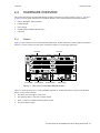
Hardware Installation . . . . . . . . . . . . . . . . . . . . . . . . . . . . . . . . . . . . . . . . . . 3-1
3.1
3.1.1
3.1.2
Safety Considerations . . . . . . . . . . . . . . . . . . . . . . . . . . . . . . . . . . . . . . . . . . . . . . . . . . . . . . . . . . . . . . 3-1
Preventing Injury . . . . . . . . . . . . . . . . . . . . . . . . . . . . . . . . . . . . . . . . . . . . . . . . . . . . . . . . . . . . . . 3-1
Preventing Equipment Damage . . . . . . . . . . . . . . . . . . . . . . . . . . . . . . . . . . . . . . . . . . . . . . . . . . . 3-1
3.2
Hardware Specifications . . . . . . . . . . . . . . . . . . . . . . . . . . . . . . . . . . . . . . . . . . . . . . . . . . . . . . . . . . . . 3-2
3.3
3.3.1
3.3.2
3.3.3
3.3.4
3.3.5
3.3.6
Installing the Hardware . . . . . . . . . . . . . . . . . . . . . . . . . . . . . . . . . . . . . . . . . . . . . . . . . . . . . . . . . . . . . 3-2
Verifying Your Shipment. . . . . . . . . . . . . . . . . . . . . . . . . . . . . . . . . . . . . . . . . . . . . . . . . . . . . . . . 3-2
Installing the Chassis . . . . . . . . . . . . . . . . . . . . . . . . . . . . . . . . . . . . . . . . . . . . . . . . . . . . . . . . . . . 3-3
Installing an AC Power Supply . . . . . . . . . . . . . . . . . . . . . . . . . . . . . . . . . . . . . . . . . . . . . . . . . . . 3-4
Installing a DC Power Supply . . . . . . . . . . . . . . . . . . . . . . . . . . . . . . . . . . . . . . . . . . . . . . . . . . . . 3-6
Installing the Control Module . . . . . . . . . . . . . . . . . . . . . . . . . . . . . . . . . . . . . . . . . . . . . . . . . . . 3-10
Installing the Switching Fabric Module (RS 8600 only) . . . . . . . . . . . . . . . . . . . . . . . . . . . . . . . 3-12
Riverstone Networks RS 8000/8600 Switch Router Getting Started Guide xv
3.3.7
3.3.8
3.3.9
3.3.10
3.3.11
3.3.12
3.3.13
Installing Line Cards . . . . . . . . . . . . . . . . . . . . . . . . . . . . . . . . . . . . . . . . . . . . . . . . . . . . . . . . . . 3-13
Installing GBIC Modules into Line Cards . . . . . . . . . . . . . . . . . . . . . . . . . . . . . . . . . . . . . . . . . . 3-13
Installing ATM Physical Media Cards (PHYs) . . . . . . . . . . . . . . . . . . . . . . . . . . . . . . . . . . . . . . 3-16
Multi-rate WAN Line Card and WICs . . . . . . . . . . . . . . . . . . . . . . . . . . . . . . . . . . . . . . . . . . . . . 3-17
SRP Line Cards and Bridge Mate Module . . . . . . . . . . . . . . . . . . . . . . . . . . . . . . . . . . . . . . . . . . 3-19
Installing SFP Transceivers . . . . . . . . . . . . . . . . . . . . . . . . . . . . . . . . . . . . . . . . . . . . . . . . . . . . . 3-20
Attaching the Network Cables to Line Cards. . . . . . . . . . . . . . . . . . . . . . . . . . . . . . . . . . . . . . . . 3-21
4
Initial Configuration . . . . . . . . . . . . . . . . . . . . . . . . . . . . . . . . . . . . . . . . . . . 4-1
4.1
Powering on the RS 8000/8600 . . . . . . . . . . . . . . . . . . . . . . . . . . . . . . . . . . . . . . . . . . . . . . . . . . . . . . . 4-1
4.2
4.2.1
4.2.2
Starting the Command Line Interface . . . . . . . . . . . . . . . . . . . . . . . . . . . . . . . . . . . . . . . . . . . . . . . . . . 4-4
CLI Access Modes . . . . . . . . . . . . . . . . . . . . . . . . . . . . . . . . . . . . . . . . . . . . . . . . . . . . . . . . . . . . . 4-4
Basic Line Editing Commands. . . . . . . . . . . . . . . . . . . . . . . . . . . . . . . . . . . . . . . . . . . . . . . . . . . . 4-5
4.3
4.3.1
4.3.2
4.3.3
Configuration Changes and Saving the Configuration File. . . . . . . . . . . . . . . . . . . . . . . . . . . . . . . . . . 4-6
Activating the Configuration Commands in the Scratchpad . . . . . . . . . . . . . . . . . . . . . . . . . . . . . 4-6
Saving the Active Configuration to the Startup Configuration File. . . . . . . . . . . . . . . . . . . . . . . . 4-7
Viewing the Current Configuration . . . . . . . . . . . . . . . . . . . . . . . . . . . . . . . . . . . . . . . . . . . . . . . . 4-8
4.4
Setting the Basic System Information . . . . . . . . . . . . . . . . . . . . . . . . . . . . . . . . . . . . . . . . . . . . . . . . . . 4-9
4.5
4.5.1
Setting Up Passwords . . . . . . . . . . . . . . . . . . . . . . . . . . . . . . . . . . . . . . . . . . . . . . . . . . . . . . . . . . . . . 4-12
If You Forget Your Passwords . . . . . . . . . . . . . . . . . . . . . . . . . . . . . . . . . . . . . . . . . . . . . . . . . . . 4-13
4.6
4.6.1
4.6.2
4.6.3
Setting Up SNMP . . . . . . . . . . . . . . . . . . . . . . . . . . . . . . . . . . . . . . . . . . . . . . . . . . . . . . . . . . . . . . . . 4-15
Setting the Community string. . . . . . . . . . . . . . . . . . . . . . . . . . . . . . . . . . . . . . . . . . . . . . . . . . . . 4-15
Improving SNMP Security . . . . . . . . . . . . . . . . . . . . . . . . . . . . . . . . . . . . . . . . . . . . . . . . . . . . . . 4-16
Supported MIBs . . . . . . . . . . . . . . . . . . . . . . . . . . . . . . . . . . . . . . . . . . . . . . . . . . . . . . . . . . . . . . 4-17
4.7
Setting the DNS Domain Name and Address . . . . . . . . . . . . . . . . . . . . . . . . . . . . . . . . . . . . . . . . . . . 4-19
4.8
Setting the SYSLOG Parameters. . . . . . . . . . . . . . . . . . . . . . . . . . . . . . . . . . . . . . . . . . . . . . . . . . . . . 4-21
4.9
4.9.1
4.9.2
4.9.3
Using Redundant Control Modules . . . . . . . . . . . . . . . . . . . . . . . . . . . . . . . . . . . . . . . . . . . . . . . . . . . 4-22
Fail Over. . . . . . . . . . . . . . . . . . . . . . . . . . . . . . . . . . . . . . . . . . . . . . . . . . . . . . . . . . . . . . . . . . . . 4-23
Communicating with the Backup Control Module . . . . . . . . . . . . . . . . . . . . . . . . . . . . . . . . . . . 4-24
Things to Remember when Using Redundant Control Modules . . . . . . . . . . . . . . . . . . . . . . . . . 4-25
5
Managing Software . . . . . . . . . . . . . . . . . . . . . . . . . . . . . . . . . . . . . . . . . . . . 5-1
5.1
Upgrading System Image Software . . . . . . . . . . . . . . . . . . . . . . . . . . . . . . . . . . . . . . . . . . . . . . . . . . . . 5-1
5.2
Upgrading Boot PROM Software . . . . . . . . . . . . . . . . . . . . . . . . . . . . . . . . . . . . . . . . . . . . . . . . . . . . . 5-3
5.3
5.3.1
5.3.2
Loading Software from the Network. . . . . . . . . . . . . . . . . . . . . . . . . . . . . . . . . . . . . . . . . . . . . . . . . . . 5-6
Loading Image Software from a TFTP Server . . . . . . . . . . . . . . . . . . . . . . . . . . . . . . . . . . . . . . . . 5-6
Loading Image Software from a BootP/TFTP Server . . . . . . . . . . . . . . . . . . . . . . . . . . . . . . . . . . 5-8
5.4
5.4.1
Hitless Software Upgrade . . . . . . . . . . . . . . . . . . . . . . . . . . . . . . . . . . . . . . . . . . . . . . . . . . . . . . . . . . . 5-9
Hitless Upgrade Example . . . . . . . . . . . . . . . . . . . . . . . . . . . . . . . . . . . . . . . . . . . . . . . . . . . . . . . 5-10
5.5
5.5.1
5.5.2
Upgrading FPGA Code . . . . . . . . . . . . . . . . . . . . . . . . . . . . . . . . . . . . . . . . . . . . . . . . . . . . . . . . . . . . 5-12
Upgrading FPGA Code from a TFTP Server . . . . . . . . . . . . . . . . . . . . . . . . . . . . . . . . . . . . . . . . 5-12
Upgrading FPGA Code from a Flash RAM Card . . . . . . . . . . . . . . . . . . . . . . . . . . . . . . . . . . . . 5-13
A
Troubleshooting . . . . . . . . . . . . . . . . . . . . . . . . . . . . . . . . . . . . . . . . . . . . . A-1
B
International SaFety Information . . . . . . . . . . . . . . . . . . . . . . . . . . . . . . . . . B-1
xvi
Riverstone Networks RS 8000/8600 Switch Router Getting Started Guide
B.1
B.1.1
CONSIDERACIONES DE SEGURIDAD . . . . . . . . . . . . . . . . . . . . . . . . . . . . . . . . . . . . . . . . . . . . . .B-1
Prevención de Lesiones . . . . . . . . . . . . . . . . . . . . . . . . . . . . . . . . . . . . . . . . . . . . . . . . . . . . . . . . .B-1
Index. . . . . . . . . . . . . . . . . . . . . . . . . . . . . . . . . . . . . . . . . . . . . . . . . . . . Index-1
Riverstone Networks RS 8000/8600 Switch Router Getting Started Guide xvii
xviii Riverstone Networks RS 8000/8600 Switch Router Getting Started Guide
LIST OF FIGURES
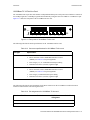
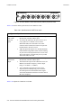
Figure 2-1
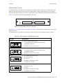
Front view of a fully loaded RS 8000 chassis. . . . . . . . . . . . . . . . . . . . . . . . . . . . . . . . . . . . . . . . . . . . 2-9
Figure 2-2
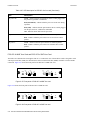
Front view of a fully loaded RS 8600 chassis. . . . . . . . . . . . . . . . . . . . . . . . . . . . . . . . . . . . . . . . . . . 2-10
Figure 2-3
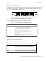
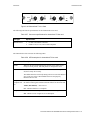
Front panel of the Control Module . . . . . . . . . . . . . . . . . . . . . . . . . . . . . . . . . . . . . . . . . . . . . . . . . . . 2-11
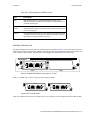
Figure 2-4
Front view of an RS 8000 AC power supply . . . . . . . . . . . . . . . . . . . . . . . . . . . . . . . . . . . . . . . . . . . 2-14
Figure 2-5
Front view of an RS 8600 AC power supply . . . . . . . . . . . . . . . . . . . . . . . . . . . . . . . . . . . . . . . . . . . 2-15
Figure 2-6
Front view of an RS 8000 DC power supply . . . . . . . . . . . . . . . . . . . . . . . . . . . . . . . . . . . . . . . . . . . 2-16
Figure 2-7
Front view of an RS 8600 DC power supply . . . . . . . . . . . . . . . . . . . . . . . . . . . . . . . . . . . . . . . . . . . 2-16
Figure 2-8
Front panel of RS 8600 Switching Fabric module . . . . . . . . . . . . . . . . . . . . . . . . . . . . . . . . . . . . . . . 2-17
Figure 2-9
Front panel of 10/100Base-TX line card. . . . . . . . . . . . . . . . . . . . . . . . . . . . . . . . . . . . . . . . . . . . . . . 2-18
Figure 2-10 10/100Base-TX RJ-45 connector . . . . . . . . . . . . . . . . . . . . . . . . . . . . . . . . . . . . . . . . . . . . . . . . . . . . 2-20
Figure 2-11 Front panel of 10/100Base-TX line card. . . . . . . . . . . . . . . . . . . . . . . . . . . . . . . . . . . . . . . . . . . . . . . 2-21
Figure 2-12 10/100Base-TX RJ-45 connector . . . . . . . . . . . . . . . . . . . . . . . . . . . . . . . . . . . . . . . . . . . . . . . . . . . . 2-22
Figure 2-13 Front panel of 4 MB 100Base-FX line card (MMF) . . . . . . . . . . . . . . . . . . . . . . . . . . . . . . . . . . . . . . 2-23
Figure 2-14 Front panel of 100Base-FX SFP line card . . . . . . . . . . . . . . . . . . . . . . . . . . . . . . . . . . . . . . . . . . . . . 2-24
Figure 2-15 Front panel of 1000Base-SX line card . . . . . . . . . . . . . . . . . . . . . . . . . . . . . . . . . . . . . . . . . . . . . . . . 2-26
Figure 2-16 Front panel of 1000Base-LX line card . . . . . . . . . . . . . . . . . . . . . . . . . . . . . . . . . . . . . . . . . . . . . . . . 2-28
Figure 2-17 Front panel of 1000Base-LLX line card . . . . . . . . . . . . . . . . . . . . . . . . . . . . . . . . . . . . . . . . . . . . . . . 2-30
Figure 2-18 Front panel of 1000Base-T line card. . . . . . . . . . . . . . . . . . . . . . . . . . . . . . . . . . . . . . . . . . . . . . . . . . 2-31
Figure 2-19 1000Base-T RJ-45 connector . . . . . . . . . . . . . . . . . . . . . . . . . . . . . . . . . . . . . . . . . . . . . . . . . . . . . . . 2-32
Figure 2-20 Front panel of MPLS GBIC line card with one GBIC installed . . . . . . . . . . . . . . . . . . . . . . . . . . . . . 2-34
Figure 2-21 GBIC modules. . . . . . . . . . . . . . . . . . . . . . . . . . . . . . . . . . . . . . . . . . . . . . . . . . . . . . . . . . . . . . . . . . . 2-34
Figure 2-22 Gigabit GBIC line cards with one GBIC installed . . . . . . . . . . . . . . . . . . . . . . . . . . . . . . . . . . . . . . . 2-36
Figure 2-23 GBIC modules. . . . . . . . . . . . . . . . . . . . . . . . . . . . . . . . . . . . . . . . . . . . . . . . . . . . . . . . . . . . . . . . . . . 2-36
Figure 2-24 Front panel of ATM OC-3c line card . . . . . . . . . . . . . . . . . . . . . . . . . . . . . . . . . . . . . . . . . . . . . . . . . 2-39
Figure 2-25 Front panel of ATM OC-12c MMF line card . . . . . . . . . . . . . . . . . . . . . . . . . . . . . . . . . . . . . . . . . . . 2-40
Figure 2-26 Front panel of ATM OC-12c SMF line card. . . . . . . . . . . . . . . . . . . . . . . . . . . . . . . . . . . . . . . . . . . . 2-41
Figure 2-27 Front panel of POS OC-3c MMF line card . . . . . . . . . . . . . . . . . . . . . . . . . . . . . . . . . . . . . . . . . . . . . 2-42
Figure 2-28 Front panel of POS OC-3c SMF line card . . . . . . . . . . . . . . . . . . . . . . . . . . . . . . . . . . . . . . . . . . . . . 2-42
Figure 2-29 Front panel of POS OC-12c MMF line card . . . . . . . . . . . . . . . . . . . . . . . . . . . . . . . . . . . . . . . . . . . . 2-44
Figure 2-30 Front panel of POS OC-12c SMF line card . . . . . . . . . . . . . . . . . . . . . . . . . . . . . . . . . . . . . . . . . . . . 2-44
Figure 2-31 Front panel of the MPLS POS-OC3c line card . . . . . . . . . . . . . . . . . . . . . . . . . . . . . . . . . . . . . . . . . . 2-45
Figure 2-32 Front panel of the MPLS POS-OC12c line card . . . . . . . . . . . . . . . . . . . . . . . . . . . . . . . . . . . . . . . . . 2-46
Figure 2-33 Front panel of Quad Serial – CE WAN line card . . . . . . . . . . . . . . . . . . . . . . . . . . . . . . . . . . . . . . . . 2-47
Figure 2-34 LFH-60 high density connector. . . . . . . . . . . . . . . . . . . . . . . . . . . . . . . . . . . . . . . . . . . . . . . . . . . . . . 2-49
Riverstone Networks RS 8000/8600 Switch Router Getting Started Guide xix
Figure 2-35 Front panel of Dual HSSI WAN line card. . . . . . . . . . . . . . . . . . . . . . . . . . . . . . . . . . . . . . . . . . . . . . 2-49
Figure 2-36 50-pin HSSI connector . . . . . . . . . . . . . . . . . . . . . . . . . . . . . . . . . . . . . . . . . . . . . . . . . . . . . . . . . . . . 2-51
Figure 2-37 Cable Modem Termination Service (CMTS) 4-port line card. . . . . . . . . . . . . . . . . . . . . . . . . . . . . . . 2-51
Figure 2-38 Cable Modem Termination Service (CMTS) 6-port line card. . . . . . . . . . . . . . . . . . . . . . . . . . . . . . . 2-52
Figure 2-39 Multi-Rate WAN line card with one T1 WIC . . . . . . . . . . . . . . . . . . . . . . . . . . . . . . . . . . . . . . . . . . . 2-53
Figure 2-40 T1 and E1 WICs . . . . . . . . . . . . . . . . . . . . . . . . . . . . . . . . . . . . . . . . . . . . . . . . . . . . . . . . . . . . . . . . . 2-53
Figure 2-41 Clear channel T3 and E3 WICs . . . . . . . . . . . . . . . . . . . . . . . . . . . . . . . . . . . . . . . . . . . . . . . . . . . . . . 2-54
Figure 2-42 Channelized T3 Line Card. . . . . . . . . . . . . . . . . . . . . . . . . . . . . . . . . . . . . . . . . . . . . . . . . . . . . . . . . . 2-57
Figure 2-43 SRP line card . . . . . . . . . . . . . . . . . . . . . . . . . . . . . . . . . . . . . . . . . . . . . . . . . . . . . . . . . . . . . . . . . . . . 2-58
Figure 2-44 SRP bridge module . . . . . . . . . . . . . . . . . . . . . . . . . . . . . . . . . . . . . . . . . . . . . . . . . . . . . . . . . . . . . . . 2-59
Figure 2-45 SRP line card pair shown in an RS 8000 chassis. . . . . . . . . . . . . . . . . . . . . . . . . . . . . . . . . . . . . . . . . 2-59
Figure 2-46 SRP line cards mated by bridge board. . . . . . . . . . . . . . . . . . . . . . . . . . . . . . . . . . . . . . . . . . . . . . . . . 2-60
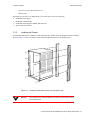
Figure 3-1
Installing the RS 8600 chassis in an equipment rack . . . . . . . . . . . . . . . . . . . . . . . . . . . . . . . . . . . . . . 3-3
Figure 3-2
Installing an AC power supply . . . . . . . . . . . . . . . . . . . . . . . . . . . . . . . . . . . . . . . . . . . . . . . . . . . . . . . 3-5
Figure 3-3
Front view of an RS 8600 DC power supply. . . . . . . . . . . . . . . . . . . . . . . . . . . . . . . . . . . . . . . . . . . . . 3-7
Figure 3-4
Relationship of wiring lugs on RS 8600 DC power supply . . . . . . . . . . . . . . . . . . . . . . . . . . . . . . . . . 3-8
Figure 3-5
Splitting each source wire to two 12-gauge wires . . . . . . . . . . . . . . . . . . . . . . . . . . . . . . . . . . . . . . . . . 3-8
Figure 3-6
Tying RS 8600 DC supply lugs together. . . . . . . . . . . . . . . . . . . . . . . . . . . . . . . . . . . . . . . . . . . . . . . . 3-9
Figure 3-7
Installing a Control Module. . . . . . . . . . . . . . . . . . . . . . . . . . . . . . . . . . . . . . . . . . . . . . . . . . . . . . . . . 3-10
Figure 3-8
Installing a switching fabric module on the RS 8600 . . . . . . . . . . . . . . . . . . . . . . . . . . . . . . . . . . . . . 3-12
Figure 3-9
Installing a line card. . . . . . . . . . . . . . . . . . . . . . . . . . . . . . . . . . . . . . . . . . . . . . . . . . . . . . . . . . . . . . . 3-13
Figure 3-10 GBIC module. . . . . . . . . . . . . . . . . . . . . . . . . . . . . . . . . . . . . . . . . . . . . . . . . . . . . . . . . . . . . . . . . . . . 3-14
Figure 3-11 Inserting a GBIC module. . . . . . . . . . . . . . . . . . . . . . . . . . . . . . . . . . . . . . . . . . . . . . . . . . . . . . . . . . . 3-14
Figure 3-12 Installing an ATM PHY card. . . . . . . . . . . . . . . . . . . . . . . . . . . . . . . . . . . . . . . . . . . . . . . . . . . . . . . . 3-16
Figure 3-13 Jumper position on Clear Channel T3 and E3 WICs. . . . . . . . . . . . . . . . . . . . . . . . . . . . . . . . . . . . . . 3-17
Figure 3-14 Inserting the WIC line card . . . . . . . . . . . . . . . . . . . . . . . . . . . . . . . . . . . . . . . . . . . . . . . . . . . . . . . . . 3-18
Figure 3-15 SRP line card showing cover plate for bridge board connector . . . . . . . . . . . . . . . . . . . . . . . . . . . . . 3-19
Figure 3-16 SRP line cards must be installed in vertically adjacent slots. . . . . . . . . . . . . . . . . . . . . . . . . . . . . . . . 3-19
Figure 3-17 SRP bridge board. . . . . . . . . . . . . . . . . . . . . . . . . . . . . . . . . . . . . . . . . . . . . . . . . . . . . . . . . . . . . . . . . 3-20
Figure 3-18 Installing SFP transceivers . . . . . . . . . . . . . . . . . . . . . . . . . . . . . . . . . . . . . . . . . . . . . . . . . . . . . . . . . 3-21
xx
Riverstone Networks RS 8000/8600 Switch Router Getting Started Guide
LIST OF TABLES
Table 2-1
ISO 7-layer model and RS 8000/8600 capabilities . . . . . . . . . . . . . . . . . . . . . . . . . . . . . . . . . . . . . . . . 2-1
Table 2-2
RS 8000/8600 specifications. . . . . . . . . . . . . . . . . . . . . . . . . . . . . . . . . . . . . . . . . . . . . . . . . . . . . . . . . 2-2
Table 2-3
RS 8000/8600 Control Module LEDs. . . . . . . . . . . . . . . . . . . . . . . . . . . . . . . . . . . . . . . . . . . . . . . . . 2-12
Table 2-4
Pin assignments DB-9 connector on Control Module. . . . . . . . . . . . . . . . . . . . . . . . . . . . . . . . . . . . . 2-13
Table 2-5
Pin assignments for RJ-45 connector on Control Module . . . . . . . . . . . . . . . . . . . . . . . . . . . . . . . . . 2-13
Table 2-6
Specifications for AC power supply . . . . . . . . . . . . . . . . . . . . . . . . . . . . . . . . . . . . . . . . . . . . . . . . . . 2-15
Table 2-7
Specifications for DC power supply . . . . . . . . . . . . . . . . . . . . . . . . . . . . . . . . . . . . . . . . . . . . . . . . . . 2-17
Table 2-8
Environmental specifications for DC power supply . . . . . . . . . . . . . . . . . . . . . . . . . . . . . . . . . . . . . . 2-17
Table 2-9
LED description for Switching Fabric . . . . . . . . . . . . . . . . . . . . . . . . . . . . . . . . . . . . . . . . . . . . . . . . 2-18
Table 2-10
Connector specifications for 10/100Base-TX line card . . . . . . . . . . . . . . . . . . . . . . . . . . . . . . . . . . . 2-19
Table 2-11
Pin assignments for 10/100Base-TX line card . . . . . . . . . . . . . . . . . . . . . . . . . . . . . . . . . . . . . . . . . . 2-19
Table 2-12
LED description for 10/100Base-TX line card . . . . . . . . . . . . . . . . . . . . . . . . . . . . . . . . . . . . . . . . . . 2-20
Table 2-13
Connector specifications for 10/100Base-TX line card . . . . . . . . . . . . . . . . . . . . . . . . . . . . . . . . . . . 2-21
Table 2-14
Pin assignments for 10/100Base-TX line card . . . . . . . . . . . . . . . . . . . . . . . . . . . . . . . . . . . . . . . . . . 2-21
Table 2-15
LED description for 10/100Base-TX line card . . . . . . . . . . . . . . . . . . . . . . . . . . . . . . . . . . . . . . . . . . 2-22
Table 2-16
Connector specifications for 100Base-FX line card . . . . . . . . . . . . . . . . . . . . . . . . . . . . . . . . . . . . . . 2-23
Table 2-17
LED description for 100Base-FX line card. . . . . . . . . . . . . . . . . . . . . . . . . . . . . . . . . . . . . . . . . . . . . 2-23
Table 2-18
SFP transceiver media specifications . . . . . . . . . . . . . . . . . . . . . . . . . . . . . . . . . . . . . . . . . . . . . . . . . 2-25
Table 2-19
Connector specifications for 1000Base-SX line card . . . . . . . . . . . . . . . . . . . . . . . . . . . . . . . . . . . . . 2-26
Table 2-20
LED description for 1000Base-SX line card. . . . . . . . . . . . . . . . . . . . . . . . . . . . . . . . . . . . . . . . . . . . 2-26
Table 2-21
Connector specifications for 1000Base-LX line card . . . . . . . . . . . . . . . . . . . . . . . . . . . . . . . . . . . . . 2-28
Table 2-22
LED description for 1000Base-LX line card . . . . . . . . . . . . . . . . . . . . . . . . . . . . . . . . . . . . . . . . . . . 2-29
Table 2-23
Connector specifications for 1000Base-LLX line cards . . . . . . . . . . . . . . . . . . . . . . . . . . . . . . . . . . . 2-30
Table 2-24
LEDs for 1000Base-LLX line card . . . . . . . . . . . . . . . . . . . . . . . . . . . . . . . . . . . . . . . . . . . . . . . . . . . 2-30
Table 2-25
Connector specifications for 1000Base-T line card . . . . . . . . . . . . . . . . . . . . . . . . . . . . . . . . . . . . . . 2-32
Table 2-26
Pin assignments for 1000Base-T line card . . . . . . . . . . . . . . . . . . . . . . . . . . . . . . . . . . . . . . . . . . . . . 2-32
Table 2-27
LED description for 1000Base-T line card . . . . . . . . . . . . . . . . . . . . . . . . . . . . . . . . . . . . . . . . . . . . . 2-33
Table 2-28
GBIC modules media specification. . . . . . . . . . . . . . . . . . . . . . . . . . . . . . . . . . . . . . . . . . . . . . . . . . . 2-34
Table 2-29
MPLS GBIC line card LEDs. . . . . . . . . . . . . . . . . . . . . . . . . . . . . . . . . . . . . . . . . . . . . . . . . . . . . . . . 2-35
Table 2-30
GBIC modules media specification. . . . . . . . . . . . . . . . . . . . . . . . . . . . . . . . . . . . . . . . . . . . . . . . . . . 2-37
Table 2-31
Gigabit GBIC line card LEDs . . . . . . . . . . . . . . . . . . . . . . . . . . . . . . . . . . . . . . . . . . . . . . . . . . . . . . . 2-37
Table 2-32
PHY modules for ATM Multi-rate line card. . . . . . . . . . . . . . . . . . . . . . . . . . . . . . . . . . . . . . . . . . . . 2-39
Table 2-33
LED description for ATM Multi-rate line card. . . . . . . . . . . . . . . . . . . . . . . . . . . . . . . . . . . . . . . . . . 2-40
Table 2-34
Cabling and connectors for ATM OC-12c line card . . . . . . . . . . . . . . . . . . . . . . . . . . . . . . . . . . . . . . 2-41
Riverstone Networks RS 8000/8600 Switch Router Getting Started Guide xxi
Table 2-35
LED description for ATM OC-12c line card. . . . . . . . . . . . . . . . . . . . . . . . . . . . . . . . . . . . . . . . . . . . 2-41
Table 2-36
Cabling and connectors for POS OC-3c line card . . . . . . . . . . . . . . . . . . . . . . . . . . . . . . . . . . . . . . . . 2-43
Table 2-37
LED description for POS OC-3c line card . . . . . . . . . . . . . . . . . . . . . . . . . . . . . . . . . . . . . . . . . . . . . 2-43
Table 2-38
Connector specifications for POS OC-12c line card . . . . . . . . . . . . . . . . . . . . . . . . . . . . . . . . . . . . . . 2-44
Table 2-39
LED description for POS OC-12c line card . . . . . . . . . . . . . . . . . . . . . . . . . . . . . . . . . . . . . . . . . . . . 2-45
Table 2-40
Cabling and connectors for MPLS POS OC-3c/OC-12c line cards . . . . . . . . . . . . . . . . . . . . . . . . . . 2-46
Table 2-41
LED description for MPLS POS OC-3c/OC-12c line card . . . . . . . . . . . . . . . . . . . . . . . . . . . . . . . . . 2-46
Table 2-42
Connector specifications for quad serial line card. . . . . . . . . . . . . . . . . . . . . . . . . . . . . . . . . . . . . . . . 2-47
Table 2-43
Quad serial cables and connector types . . . . . . . . . . . . . . . . . . . . . . . . . . . . . . . . . . . . . . . . . . . . . . . . 2-48
Table 2-44
Pin assignments for quad serial line cards. . . . . . . . . . . . . . . . . . . . . . . . . . . . . . . . . . . . . . . . . . . . . . 2-48
Table 2-45
LED description for quad serial line card . . . . . . . . . . . . . . . . . . . . . . . . . . . . . . . . . . . . . . . . . . . . . . 2-49
Table 2-46
Connector specifications for dual HSSI line card . . . . . . . . . . . . . . . . . . . . . . . . . . . . . . . . . . . . . . . . 2-50
Table 2-47
Pin assignments for dual HSSI line card . . . . . . . . . . . . . . . . . . . . . . . . . . . . . . . . . . . . . . . . . . . . . . . 2-50
Table 2-48
LED description for Dual HSSI line card . . . . . . . . . . . . . . . . . . . . . . . . . . . . . . . . . . . . . . . . . . . . . . 2-51
Table 2-49
Specifications for CMTS line cards. . . . . . . . . . . . . . . . . . . . . . . . . . . . . . . . . . . . . . . . . . . . . . . . . . . 2-52
Table 2-50
LED description for CMTS line card . . . . . . . . . . . . . . . . . . . . . . . . . . . . . . . . . . . . . . . . . . . . . . . . . 2-53
Table 2-51
Specifications for T1 WIC card. . . . . . . . . . . . . . . . . . . . . . . . . . . . . . . . . . . . . . . . . . . . . . . . . . . . . . 2-54
Table 2-52
Specifications for E1 WIC card. . . . . . . . . . . . . . . . . . . . . . . . . . . . . . . . . . . . . . . . . . . . . . . . . . . . . . 2-54
Table 2-53
Specifications for Clear Channel T3 WIC card. . . . . . . . . . . . . . . . . . . . . . . . . . . . . . . . . . . . . . . . . . 2-54
Table 2-54
Specifications for Clear Channel E3 WIC card. . . . . . . . . . . . . . . . . . . . . . . . . . . . . . . . . . . . . . . . . . 2-55
Table 2-55
Pin assignments for T1 and E1 WICs . . . . . . . . . . . . . . . . . . . . . . . . . . . . . . . . . . . . . . . . . . . . . . . . . 2-55
Table 2-56
LEDs for Multi-rate WAN line card and WICs. . . . . . . . . . . . . . . . . . . . . . . . . . . . . . . . . . . . . . . . . . 2-56
Table 2-57
Connector specifications for channelized T3 line card . . . . . . . . . . . . . . . . . . . . . . . . . . . . . . . . . . . . 2-57
Table 2-58
LED description for channelized T3 line card. . . . . . . . . . . . . . . . . . . . . . . . . . . . . . . . . . . . . . . . . . . 2-57
Table 2-59
Qualified SFPs for SRP line cards. . . . . . . . . . . . . . . . . . . . . . . . . . . . . . . . . . . . . . . . . . . . . . . . . . . . 2-60
Table 2-60
LED description for SRP line card . . . . . . . . . . . . . . . . . . . . . . . . . . . . . . . . . . . . . . . . . . . . . . . . . . . 2-60
Table 3-1
Physical and Environmental Specifications. . . . . . . . . . . . . . . . . . . . . . . . . . . . . . . . . . . . . . . . . . . . . . 3-2
Table 3-2
Physical Specifications for AC Power Supply . . . . . . . . . . . . . . . . . . . . . . . . . . . . . . . . . . . . . . . . . . . 3-5
Table 3-3
Environmental Specifications for AC Power Supply . . . . . . . . . . . . . . . . . . . . . . . . . . . . . . . . . . . . . . 3-5
Table 3-4
Physical Specifications for DC Power Supply . . . . . . . . . . . . . . . . . . . . . . . . . . . . . . . . . . . . . . . . . . . 3-6
Table 3-5
Environmental Specifications for DC Power Supply . . . . . . . . . . . . . . . . . . . . . . . . . . . . . . . . . . . . . . 3-7
Table 3-6
Jumper default settings . . . . . . . . . . . . . . . . . . . . . . . . . . . . . . . . . . . . . . . . . . . . . . . . . . . . . . . . . . . . 3-17
Table 4-1
CLI access modes . . . . . . . . . . . . . . . . . . . . . . . . . . . . . . . . . . . . . . . . . . . . . . . . . . . . . . . . . . . . . . . . . 4-4
Table 4-2
Common CLI line editing commands . . . . . . . . . . . . . . . . . . . . . . . . . . . . . . . . . . . . . . . . . . . . . . . . . . 4-5
Table 4-3
Configuration file contents . . . . . . . . . . . . . . . . . . . . . . . . . . . . . . . . . . . . . . . . . . . . . . . . . . . . . . . . . . 4-6
Table 4-4
Supported MIBs. . . . . . . . . . . . . . . . . . . . . . . . . . . . . . . . . . . . . . . . . . . . . . . . . . . . . . . . . . . . . . . . . . 4-17
Table 4-5
Types of SYSLOG messages. . . . . . . . . . . . . . . . . . . . . . . . . . . . . . . . . . . . . . . . . . . . . . . . . . . . . . . . 4-21
Table 4-6
Examples of message types . . . . . . . . . . . . . . . . . . . . . . . . . . . . . . . . . . . . . . . . . . . . . . . . . . . . . . . . . 4-21
Table A-1
Troubleshooting. . . . . . . . . . . . . . . . . . . . . . . . . . . . . . . . . . . . . . . . . . . . . . . . . . . . . . . . . . . . . . . . . . A-1
xxii Riverstone Networks RS 8000/8600 Switch Router Getting Started Guide
1 ABOUT THIS GUIDE
This guide provides a general overview of the 8-slot and 16-slot Riverstone Networks, Inc. RS 8000 and RS 8600
hardware and software features. Also, it provides procedures for installing the RS 8000 and RS 8600. For product
information not available in this guide, see the manuals listed in Section 1.2, "Related Documentation."
1.1
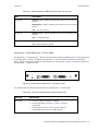
HOW TO USE THIS GUIDE
If You Want To...
See...
Get an overview of the RS 8000 and RS 8600
software and hardware features
Chapter 2, "Introduction"
Install the RS 8000 or RS 8600 hardware
Chapter 3, "Hardware Installation"
Install the RS 8000 or RS 8600 software, boot the Chapter 4, "Initial Configuration"
software, and set up the unit
Troubleshoot installation problems
1.2
Appendix A, "Troubleshooting"
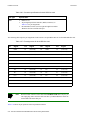
RELATED DOCUMENTATION
The Riverstone RS Switch Router documentation set includes the following items. Refer to these other documents
to learn more about your product.
For Information About...
See the...
How to use Command Line Interface (CLI)
commands to configure and manage the
RS 8000 or RS 8600
Riverstone RS Switch Router User Guide
The complete syntax for all CLI commands
Riverstone RS Switch Router Command Line
Interface Reference Manual
System messages
Riverstone RS Switch Router Message Reference
Manual
Riverstone Networks RS 8000/8600 Switch Router Getting Started Guide 1-1
Related Documentation
1-2 Riverstone Networks RS 8000/8600 Switch Router Getting Started Guide
About This Guide
2 INTRODUCTION
The 8-slot and 16-slot Riverstone Networks, Inc. RS 8000 and RS 8600 provide non-blocking, wire-speed layer-2
(switching), layer-3 (routing), and layer-4 (application) switching. This chapter provides a basic overview of the
RS 8000 and RS 8600 software and hardware feature set.
•
If you want to skip this information and install the RS now, see Chapter 3, "Hardware
Installation."
•
If you want to boot the RS software and perform basic configuration tasks now, see Chapter 4,
"Initial Configuration."
Note
2.1
For the latest operating software and user documentation, check the
Riverstone Networks web site at www.riverstonenet.com.
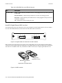
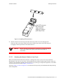
FUNCTIONAL LAYER TERMINOLOGY
This guide, and other RS documentation, refers to layer-2 (L2), layer-3 (L3), and layer-4 (L4) switching and
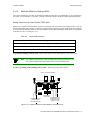
routing. These layers are based on the International Standards Organization (ISO) 7-layer reference model. Here
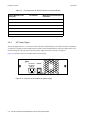
is an example of that model. The RS operates within the layers that are not shaded. Notice that layer 2 is divided
into a MAC layer, an LLC layer, and an LLC2 layer. The RS operates at the MAC and LLC layers.
Table 2-1
ISO 7-layer model and RS 8000/8600 capabilities
Layer 7
Application
Layer 6
Presentation
Layer 5
Session
Layer 4
Transport
TCP/UDP - application
Layer 3
Network
IP/IPX - routing
LLC2
Layer 2
Layer 1
LLC
MAC
Bridging
Physical
Physical Interfaces
Riverstone Networks RS 8000/8600 Switch Router Getting Started Guide 2-1
Specifications
2.2
Introduction
SPECIFICATIONS
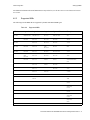
The following table lists the basic hardware and software specifications for the RS 8000 and RS 8600.
Table 2-2
RS 8000/8600 specifications
Feature
Specification
Throughput
•
•
•
16-Gbps non-blocking switching fabric (RS 8000)
•
Up to 15 million packets-per-second routing throughput
(RS 8000)
•
•
•
•
•
•
•
•
•
•
Up to 250,000 routes
•
32 MB input/output buffering per Packet Over
SONET/SDH OC-3c port
•
64 MB input/output buffering per Packet Over
SONET/SDH OC-12c port
•
•
•
•
•
•
•
•
•
•
•
•
802.3 (10Base-T)
Capacity
Media interface
protocols
32-Gbps non-blocking switching fabric (RS 8600)
Up to 30 million packets-per-second routing throughput
(RS 8600)
Up to 2,000,000 layer-4 application flows (RS 8000)
Up to 4,000,000 layer-4 application flows (RS 8600)
400,000 layer-2 MAC addresses (RS 8000)
800,000 layer-2 MAC addresses (RS 8600)
4,096 Virtual LANs (VLANs)
20,000 layer-2 security and access-control filters
3 MB input/output buffering per Gigabit port
1 MB input/output buffering per 10/100 port
20 MB shared input/output buffering across WAN ports
on a WAN module
802.3u (100Base-TX, 100Base-FX)
802.3x (1000Base-SX, 1000Base-LX)
802.3z (1000Base-SX, 1000Base-LX)
DS-3/E-3 (ATM Multi-rate and Channelized)
OC-3c (ATM Multi-rate and POS)
OC-12c (POS)
T1/E1 (WAN Multi-rate)
T3 (Channelized)
T3 Clear Channel
E3 Clear Channel
CMTS (DOCSIS 1.0, EuroDOCSIS 1.0)
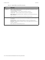
2-2 Riverstone Networks RS 8000/8600 Switch Router Getting Started Guide
Introduction
Specifications
Table 2-2
RS 8000/8600 specifications (Continued)
Feature
Specification
Routing protocols
•
•
•
IP: RIP v1/v2, OSPF, BGP 2, 3, 4, IS-IS
•
•
LER and LSR complete functionality
•
OSPF-TE and ISIS-TE traffic engineering extensions
with support for online CSPF
•
•
•
•
802.1d Spanning Tree
RMON
•
RMON v1/v2 for each port
Management
•
•
SNMP v1, v2
•
•
Traffic from specific ports
•
•
Line cards
•
•
Switching Fabric Modules (RS 8600 only)
•
•
•
•
Redundant power supplies
MPLS
Bridging and VLAN
protocols
Port mirroring
Hot swapping
Redundancy
IPX: RIP, SAP
Multicast: IGMP, DVMRP, GARP/GVRP
RSVP-TE and LDP for label distribution and dynamic
LSP creation
802.1Q (VLAN trunking)
Rapid Spanning Tree Protocol (RSTP)
Per-VLAN Spanning Tree (PVST)
Emacs-like Command Line Interface (CLI)
Traffic to specific expansion slots (line cards)
Control module (when redundant Control Module is
installed and online)
Power Supply (when redundant supply is installed and
online)
Redundant Control Modules
Redundant Switching Fabric Modules (RS 8600 only)
Virtual Router Redundancy Protocol (VRRP)
Riverstone Networks RS 8000/8600 Switch Router Getting Started Guide 2-3
Software Overview
2.3
Introduction
SOFTWARE OVERVIEW
This section describes the features and capabilities of the RS 8000/8600 in greater detail.
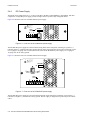
2.3.1
Bridging
The RS provides the following types of wire-speed bridging:
Address-based bridging – The RS performs this type of bridging by looking up a packet’s destination address in an
L2 lookup table on the line card that received the packet from the network. The L2 lookup table indicates the exit
port(s) for the bridged packet. If the packet is addressed to the router’s own MAC address, the packet is routed rather
than bridged.
Flow-based bridging – The RS performs this type of bridging by looking up a packet’s source and destination address
in an L2 lookup table on the line card that received the packet from the network.
Your choice of bridging method does not affect RS performance. However, address-based bridging requires fewer table
entries. Alternately, while flow-based bridging uses more table entries, it provides tighter management and control
over bridged traffic, and greater resolution to RMON I statistics.
The RS ports perform address-based bridging by default, but can be configured to perform flow-based bridging on a
per-port basis. A port cannot be configured to perform both types of bridging at the same time.
2.3.2
Port and Protocol VLANs
The RS supports the following types of Virtual LANs (VLANs):
Port-based VLANs – A port-based VLAN is a set of ports that comprises a layer-2 broadcast domain. The RS confines
MAC-layer broadcasts to the ports in the VLAN on which the broadcast originates. RS ports outside the VLAN do not
receive the broadcast.
Protocol-based VLANs – A protocol-based VLAN is a named set of ports that comprises an IP, IPX, AppleTalk,
DECNet, SNA, IPv6, or L2 broadcast domain. The RS confines protocol-specific broadcasts to the ports within the
protocol-based VLAN. Protocol-based VLANs sometimes are called subnet VLANs or layer-3 VLANs.
You can include the same port in more than one VLAN, even in both port-based and protocol-based VLANs.
Moreover, you can define VLANs that span across multiple RS switch routers. To simplify VLAN administration, the
RS supports 802.1Q trunk ports, which allow you to use a single port to “trunk” traffic from multiple VLANs to
another RS or to a switch that supports 802.1Q.
2.3.3
Routing
The RS provides wire-speed routing for the following protocols:
IP – protocol that switching and routing devices use for moving traffic within the Internet and within many corporate
intranets
IPX – protocol by Novell used in NetWare products
2-4 Riverstone Networks RS 8000/8600 Switch Router Getting Started Guide
Introduction
Software Overview
Note
All other protocols that require routing must be tunneled using IP.
By default, the RS uses one MAC address for all interfaces. The RS can be configured to have a separate MAC address
for each IP interface and a separate MAC address for each IPX interface. When the RS receives a packet whose
destination MAC address is one of the router’s IP or IPX interface MAC addresses, the line card that received the
packet from the network uses information in the line card’s L3 lookup tables (or information supplied by the Control
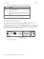
Module) to route the packet to its IP destination(s). (See Section 2.4.4, "Control Module" for information about the
Control Module.)
You can add secondary IP addresses to the same IP interface, however, you can create only one IP and IPX interface
on a single port or VLAN. When you add an interface to a set of ports, you are adding a VLAN to those ports. Ports
that contain IP and IPX interfaces can still perform layer-2 bridging.
IP Routing
The RS supports the following IP unicast routing protocols:
•
•
•
•
RIP v1 and RIP v2
OSPF v2
BGP 2,3,4
IS-IS
IP interfaces do not use a specific routing protocol by default. When you configure an interface for routing, you also
specify the routing protocol that the interface will use.
IP Multicast Routing
The RS supports the following IP multicast routing protocols:
•
•
•
IGMP
DVMRP
GARP/GVRP
The RS does not use a specific IP multicast routing protocol by default. When you configure an interface for IP
multicast, you also specify the routing protocol you want the interface to use.
IPX Routing
The RS supports the following IPX routing protocols:
IPX RIP – a version of the Routing Information Protocol (RIP) tailored for IPX
IPX SAP – the Service Advertisement Protocol, which allows hosts attached to an IPX network to reach printers, file
servers, and other services
By default, IPX routing is enabled on the RS when an IPX interface is created.
Riverstone Networks RS 8000/8600 Switch Router Getting Started Guide 2-5
Software Overview
2.3.4
Introduction
Layer-4 Switching
In addition to layer-2 bridging and layer-3 routing, the RS performs layer-4 switching. layer-4 switching is based on
applications and flows.
Layer-4 Applications – The RS understands the application for which an IP or IPX packet contains data and therefore
enables you to manage and control traffic on an application basis. For IP traffic, the RS looks at the packet’s TCP or
UDP port number to determine the application. For IPX packets, the RS looks at the destination socket to determine
the application.
Layer-4 Flows – The RS can store layer-4 flows on each line card. A layer-4 flow consists of the source and destination
addresses in the IP or IPX packet combined with the TCP or UDP source and destination port number (for IP) or the
source and destination socket (for IPX). You can therefore manage and control individual flows between hosts on an
individual application basis.
A single host can have many individual layer-4 entries in the RS. For example, an IP host might have separate layer-4
application entries for email, FTP, HTTP, and so on, or separate layer-4 flow entries for specific email destinations and
for specific FTP and Web connections.
2.3.5
MPLS Support
Multi Protocol Label Switching (MPLS) is supported on the RS 8000/8600 through software and through hardware on
the G8M-GBCMM-02 Gigabit Ethernet line card, G8M-PO3MM-02 2-port OC-3 line card, and G8M-PO3MM-02
2-port OC-12 line card. The following MPLS capabilities are supported on the RS 8000/8600:
•
Complete Label Edge Router (LER) and Label Switching Router (LSR) functionality with no impact
on performance
•
Label generation and swapping, along with push and pop operations for supporting multiple levels
of label stacking
•
•
•
•
•
Tunneling of layer-2 Ethernet over MPLS (for Gigabit Ethernet card)
•
•
Standby LSPs and fail over
•
MPLS VPNs over BGP
Tunneling of layer-2 bridged PPP traffic over MPLS (for OC-3/OC-12 modules)
Support for thousands of label switched paths
Support for static and dynamic creation of LSPs
Label Distribution Protocol (LDP) and Resource Reservation Protocol with Traffic Engineering
(RSVP-TE) for label distribution and dynamic Label Switched Path (LSP) creation with support for
LDP over LDP and LDP over RSVP, allowing different tunneling schemes
Traffic engineering extensions to OSPF and IS-IS, along with Constrained Shortest Path First
(CSPF)
2.3.6
Security
The bridging, routing, and application (layer-2, layer-3, and layer-4) support described in previous sections enables
you to implement security strategies that meet specific needs. For layer-2, a wide range of bridging filters are available.
Additionally, all layers can be protected using Access Control Lists (ACLs) filters. You can implement the following
types of filters and ACLs to secure traffic on the RS:
•
Layer-2 source filters (block bridge traffic based on source MAC address)
2-6 Riverstone Networks RS 8000/8600 Switch Router Getting Started Guide
Introduction
•
•
•
•
•
•
•
Software Overview
Layer-2 destination filters (block bridge traffic based on destination MAC address)
Layer-2 flow filters (block bridge traffic based on specific source-destination pairs)
Layer-3 source ACLs (block IP or IPX traffic based on source IP or IPX address)
Layer-3 destination ACLs (block IP or IPX traffic based on destination IP or IPX address)
Layer-3 flow ACLs (block IP or IPX traffic based on specific source-destination address pairs)
Layer-4 flow ACLs (block traffic based on application flows)
Layer-4 application ACLs (block traffic based on UDP or TCP source and destination ports for IP
or source and destination sockets for IPX)
In addition to filtering and ACL, the RS also provides login security in the form of TACACS, TACACS+, RADIUS,
and Secure Session Shells (SSH) version 1.5.
2.3.7
Quality of Service
Although the RS supplies non-blocking, wire-speed throughput, you can configure the RS to apply Quality of Service
(QoS) policies during peak periods to guarantee service to specific hosts, applications, and flows (source-destination
pairs). This is especially useful in networks where the traffic level can exceed the network capacity.
QoS policies can be configured for the following types of traffic:
•
•
•
•
Layer-2 prioritization (802.1p)
Layer-3 source-destination flows
Layer-4 source-destination flows
Layer-4 application flows
QoS mechanisms supported on the RS 8000/8600 include the following:
•
•
•
•
•
•
Traffic control queuing
Weighted random early detection
Weighted fair queuing
Strict priority queuing
QoS traffic control queues
ToS octet rewrites
Note
2.3.8
Traffic control queuing is based on assigning traffic to one of four queues: control,
high, medium, and low. Control traffic (routing protocols, and so on) has the
highest priority, high the second highest, and so on. The default priority for all
traffic is low.
Statistics
The RS can provide extensive statistical data on demand. You can access the following types of statistics:
Layer-2 RMON and MIB II Statistics – Port statistics for normal packets and for errors (packets in, packets out, CRC
errors, and so on)
Riverstone Networks RS 8000/8600 Switch Router Getting Started Guide 2-7
Software Overview
Introduction
Layer-3 RMON v2 Statistics – Statistics for ICMP, IP, IP-interface, IP routing, IP multicast, VLAN
Layer-4 RMON v2 Statistics – Statistics for TCP and UDP
LFAP – Light-weight File Accounting Protocol
Open APIs – Slate and FAS Lite.
2.3.9
Web Hosting Features
The RS provides features that support and improve performance for high-capacity web access:
Load balancing – allows incoming HTTP requests to a company’s web site to be distributed across several physical
servers. If one server should fail, other servers can pick up the workload.
Web caching – allows HTTP requests from internal users to Internet sites to be redirected to cached web objects on
local servers. Not only is response time faster, since requests can be handled locally, but overall WAN bandwidth usage
is reduced.
Session persistence – In certain situations where load balancing is being used, it may be critical that all traffic for the
client be directed to the same physical server for the duration of the session; this is the concept of session persistence.
TCP persistence – a binding is determined by the matching the source IP/port address as well as the virtual
destination IP/port address.
SSL persistence – a binding is determined by matching the source IP address and the virtual destination IP/port
address. Note that requests from any source socket with the client IP address are considered part of the same
session.
Sticky persistence – a binding is determined by matching the source and destination IP addresses only. This
allows all requests from a client to the same virtual address to be directed to the same load balancing server.
Virtual private network (VPN) persistence – for VPN traffic using Encapsulated Security Payload (ESP) mode
of IPSec, a binding is determined by matching the source and destination IP addresses in the secure key transfer
request to subsequent client requests.
IP persistence – Used for L3 persistence of load balancing sessions.
2.3.10
Management Platforms
You can manage the RS using the following management platforms:
Command Line Interface (CLI) – An Emacs editor-like interface that accepts typed commands and responds when
applicable with messages or tables. Use the CLI to perform the basic setup procedures described in Chapter 4, "Initial
Configuration."
SNMP MIBs and traps – The RS supports SNMP v1/v2 and many standard networking MIBs. The RS’s SNMP agent
is accessed using integration software such as HP OpenView 5.x on Windows NT or Solaris 2.x, or Aprisma
SPECTRUM on Windows NT or Solaris 2.x. Setting up SNMP on the RS is described in Chapter 4, "Initial
Configuration."
2-8 Riverstone Networks RS 8000/8600 Switch Router Getting Started Guide
Introduction
2.4
Hardware Overview
HARDWARE OVERVIEW
This section describes the RS 8000/8600 hardware modules with which you will be working. Chapter 3, "Hardware
Installation" in this guide describes how to install the hardware. This section describes the following hardware:
•
•
•
•
•
Chassis, Backplane, and Fan module
Control Module
Power Supply
Switching Fabric Module (RS 8600 only)
Line cards
2.4.1
Chassis
Figure 2-1 shows the front view of a fully loaded RS 8000 chassis. The RS 8000 chassis contains eight slots, numbered
from 0 to 7. Slot 0 is in the lower left corner of the chassis and slot 7 is in the upper right corner.
Line Card
Line Card
G8M-GLXA9-02
1000BASE-LX
1
RS-8000
10/100BASE-TX
2
3
4
5
6
7
2
3
4
5
6
7
G8M-HTXA2-08
1
7
5
3
CM/1
PS2
1
10/100BASE-TX
2
3
4
5
6
7
2
3
4
5
6
7
G8M-HTXA2-08
8
CONTROL MODULE
2
G8M-HTXA2-08
8
10/100BASE-TX
G8M-CM
6
4
2
CM
PS1
1000BASE-SX
1
G8M-HTXA2-08
1
G8M-GSXA1-02
2
1
G8M-HFXA1-08
PWR
8
10/100BASE-TX
8
3
4
7
8
1
2
5
6
100BASE-FX
PWR
100-125~5A
200-240~3A
50-60 Hz
G80-PAC
100-125~5A
200-240~3A
50-60 Hz
G80-PAC
G80-CHS
Fan module
Power supply
Control module
Power supply
Figure 2-1 Front view of a fully loaded RS 8000 chassis
Figure 2-2 shows the front view of a fully loaded RS 8600 chassis. The RS 8600 chassis is similar to the RS 8000
chassis, except for the following:
•
•
•
•
The chassis can contain up to 16 line cards.
The switching fabric is stored on a separate module.
There is a slot for a redundant switching fabric module.
The power supply is larger.
Riverstone Networks RS 8000/8600 Switch Router Getting Started Guide 2-9
Hardware Overview
Introduction
Switching Fabric
module
G8M-GLXA9-02
1000BASE-LX
1
10/100BASE-TX
2
3
4
5
6
7
2
3
4
5
6
7
G8M-HTXA2-08
1
1000BASE-SX
1
G8M-HTXA2-08
1
G8M-GSXA1-02
2
G8M-HTXA2-08
8
1
10/100BASE-TX
2
10/100BASE-TX
2
3
4
5
6
7
2
3
4
5
6
7
G8M-HTXA2-08
8
1
8
10/100BASE-TX
8
RS-8600
G8M-HFXA1-08
3
4
7
8
1
2
5
6
4
7
1
2
5
8
100BASE-FX
6
G86-SWF
Switching Fabric
1000BASE-LX
1
1000BASE-SX
1
10/100BASE-TX
2
3
4
5
6
7
2
3
4
5
6
7
G8M-HTXA2-08
1
G8M-GSXA1-02
2
G8M-HTXA2-08
PWR
1
10/100BASE-TX
2
3
4
5
6
7
2
3
4
5
6
7
G8M-HTXA2-08
8
CONTROL MODULE
2
G8M-HTXA2-08
8
10/100BASE-TX
G8M-CM
PS2
3
Switching Fabric
1
PS1
G8M-HFXA1-08
G86-SWF
G8M-GLXA9-02
14
15
12
13
10
11
8
9
Fabric 2
Fabric 1
6
7
4
5
2
3
CM
CM/1
100BASE-FX
1
8
10/100BASE-TX
G8M-CM
8
CONTROL MODULE
PWR
G86-PAC
G86-PAC
SN
SN
TO REMOVE POWER TO
UNIT DISCONNECT ALL
POWER SUPPLY CORDS
TO REMOVE POWER TO
UNIT DISCONNECT ALL
POWER SUPPLY CORDS
100-125V~ 10A
200-240V~ 6A
50/60 Hz
100-125V~ 10A
200-240V~ 6A
50/60 Hz
G86-CHS
Power supply
Figure 2-2 Front view of a fully loaded RS 8600 chassis
The RS 8600 chassis contains sixteen slots, numbered from 0 to 15. Slot 0 is in the lower left corner of the chassis and
slot 15 is in the upper right corner. The RS 8600 also has slots for primary and redundant switching fabric modules.
On both the RS 8000 and RS 8600, slot 0 is labeled “CM” and contains the primary Control Module. The CM slot
cannot be used for line cards. The primary Control Module must be installed in this slot. The CM/1 slot can contain a
redundant Control Module (if you install one) or can contain a line card. Slots 2 to 7 on the RS 8000 or slots 2 to 15
on the RS 8600 can contain any line cards. (See Section 2.4.4, "Control Module" and Section 2.4.8, "RS 8000/8600
Line Cards" for information about these items.)
You can install line cards in any order in the slots. For example, you could install line cards in slots 2 and 5 and leave
the other line card slots empty. The RS provides non-blocking throughput regardless of the software features you are
using. Therefore, you do not need to “load balance” line cards by placing them in certain relationships to balance the
load on the backplane. Regardless of where you install the line cards, the backplane can provide full, non-blocking
throughput.
2-10 Riverstone Networks RS 8000/8600 Switch Router Getting Started Guide
Introduction
2.4.2
Hardware Overview
Backplane
The backplane occupies the rear of the chassis and connects the power supplies, Control Modules, and line cards
together. The power supplies use the backplane to provide power to the rest of the system. The line cards and Control
Modules use the backplane to exchange control information and packets. The backplane is installed at the factory.
Contact Riverstone Networks, Inc. if you wish to replace the backplane.
2.4.3
Fan Module
The RS contains a fan module to provide a cooling air flow across the Control Module(s) and line cards. The fan
module is located on the left side of the Control Modules and line cards. The RS 8000 fan module contains two fans;
the RS 8600 fan module contains six fans. The fan module is installed at the factory, but you can replace the module
yourself, if necessary.
Note
2.4.4
To ensure that the fan module can provide adequate cooling, always provide a
minimum of 3 inches of clearance on each side of the chassis.
Control Module
The Control Module is the RS’s central processing unit. It contains system-wide bridging and routing tables. Traffic
that does not yet have an entry in the L2 and L3/L4 lookup tables on individual line cards is sent to the Control Module.
After processing traffic, the Control Module updates the L2 and L3/L4 tables on the line cards that received the traffic.
The line cards thus “learn” about how to forward traffic.
Note
If you plan to install a redundant Control Module, see Section 4.9, "Using
Redundant Control Modules"
Figure 2-3 shows the front panel of the Control Module.
G8M-CM2-128
SYS
RST
Console
CONTROL MODULE
10/100 Mgmt
OK HBT
Online Offline
Hot
Swap
ERR DIAG
Figure 2-3 Front panel of the Control Module
Riverstone Networks RS 8000/8600 Switch Router Getting Started Guide 2-11
Hardware Overview
Introduction
Boot Flash
The Control Module has a boot flash containing the RS’s boot software and configuration files. The system software
image file typically resides on a 32 megabyte PC card, but can also be located on a TFTP server or BootP/TFTP server.
Memory Module
The Control Module uses memory to hold the routing tables and other tables. The Control Module 2 contains 128MB
of memory (in a 128MB DIMM).
The Control Module 3 contains 256MB of memory (in two 128MB DIMMs). You can obtain an RS memory upgrade
kit from Riverstone Networks, Inc. to increase memory in the Control Module 3 to 256MB.
The Control Module 5 contains 512MB of memory (in two 256MB DIMMs). You can obtain an RS memory upgrade
kit from Riverstone Networks, Inc. to increase memory in the Control module 5 to 768 MB.
External Controls and Connections
The Control Module has the following external controls.
•
•
Reset switch (RST). Use this switch to reboot the RS’s CPU.
LEDs that indicate the current status of the RS 8000/8600. Table 2-3 describes the meaning of the
Control Module LEDs
Table 2-3
RS 8000/8600 Control Module LEDs
LED
Description
OK
When this LED is on, the RS 8000/8600 and all ports are functioning correctly.
ERR
When this LED is on, a fatal system error has occurred. Activate the RS 8000/8600’s boot
PROM to reboot the system.
HBT
This LED flashes when the RS 8000/8600’s boot PROM is active.
DIAG
When this LED is on, the RS 8000/8600 is in diagnostic mode. While in diagnostic mode,
several other LEDs on the RS 8000/8600 are active, as well.
Online
When lit, this green LED indicates that the module is online and is ready to receive,
process, and send packets if configured to do so.
Offline
When lit, this amber LED indicates that the Control Module is offline (powered off) and
is ready for hot swap.
The Offline LED also is lit briefly during a reboot or reset of the RS 8000/8600.
•
PC flash card slots. These slots are used to connect the PC card to the Control Module. The
RS 8000/8600’s operating software image resides on the PC cards, and is loaded by the system at
power-up. More than one software image can reside on the PC cards, this allows for upgrades and
the changing of software versions run by the RS 8000/8600.
2-12 Riverstone Networks RS 8000/8600 Switch Router Getting Started Guide
Introduction
Hardware Overview
Note
•
The RS 8000/8600 supports the use of dual PC cards, one in slot0, the other in
slot1. Each PC card is treated as an independent file system by the RS. For detailed
information regarding the PC flash file system and the management of
configuration files, see the “Riverstone Networks RS Switch Router User Guide.”
Male DB-9 Data Communications Equipment (DCE) port for serial connection to a management
terminal. Use this port to establish a direct CLI connection to the RS. The default baud rate is 9600.
The following table lists the pin assignments for the male DB-9 connector on the Control Module and for the male
DB-9 connector on the management console.
Table 2-4
Pin assignments DB-9 connector on Control Module
Control Module DB-9
Connector (DCE)
Pin Number
Management Console DB-9
Connector (DTE)
Unused
1
Unused
TXD (transmit data)
2
RXD (receive data)
RXD (receive data)
3
TXD (transmit data)
Unused
4
Unused
GND (ground)
5
GND (ground)
DTR (data terminal ready)
6
DSR (data set ready)
CTS (clear to send)
7
RTS (request to send)
RTS (request to send)
8
CTS (clear to send)
Unused
9
Unused
•
10/100Base-TX Data Terminal Equipment (DTE) port for network (“in-band”) connection to a
management terminal. The port is configured as a Media Data Interface (MDI). Use this port to
establish a management connection to the RS over a local or bridged Ethernet segment.
The following table lists the pin assignments for the RJ-45 connector on the Control Module and for the RJ-45
connector on the network side of the cable.
Table 2-5
Pin assignments for RJ-45 connector on Control Module
Control Module RJ-45
Connector
Pin Number
Management Console RJ-45
Connector
TXD (transmit data)
1
RXD (receive data)
TXD (transmit data)
2
RXD (receive data)
Riverstone Networks RS 8000/8600 Switch Router Getting Started Guide 2-13
Hardware Overview
Table 2-5
Introduction
Pin assignments for RJ-45 connector on Control Module
Control Module RJ-45
Connector
Pin Number
Management Console RJ-45
Connector
RXD (receive data)
3
TXD (transmit data)
Unused
4
Unused
Unused
5
Unused
RXD (receive data)
6
TXD (transmit data)
Unused
7
Unused
Unused
8
Unused
2.4.5
AC Power Supply
The power supply delivers 3.3, 5, and 12 DC volts to the RS’s Control Module(s), fan modules, and other components.
A single power supply provides enough current to operate a fully configured chassis. The power supply has its own
internal cooling fan. The vent on the front of the power supply is the inlet vent for the cooling fan.
Figure 2-4 shows the front view of an RS 8000 AC power supply.
PWR
100-125~5A
200-240~3A
50-60 Hz
G80-PAC
Figure 2-4 Front view of an RS 8000 AC power supply
2-14 Riverstone Networks RS 8000/8600 Switch Router Getting Started Guide
Introduction
Hardware Overview
The RS 8600 power supply is somewhat larger than the RS 8000 power supply. Figure 2-5 shows the front view of an
RS 8600 AC power supply.
PWR
G86-PAC
SN
TO REMOVE POWER TO
UNIT DISCONNECT ALL
POWER SUPPLY CORDS
100-125V~ 10A
200-240V~ 6A
50/60 Hz
Figure 2-5 Front view of an RS 8600 AC power supply
The following table lists the specifications for the RS’s AC power supply.
Table 2-6
Specifications for AC power supply
RS Switch Router
Input Voltage
Input Current
RS 8000
100 to 125, 200 to 240 V AC
5, 3 A
RS 8600
100 to 125, 200 to 240 V AC
10, 6 A
To ensure against equipment failure, you can install a redundant power supply. When two power supplies are active in
the RS, they load share, each supply delivering approximately 50 percent of the current needed. Moreover, if one of
the power supplies fails, the other power supply immediately assumes the entire load, thus preventing any system
outage.
The AC power supply has a green status LED. When the LED is lit, the power supply is connected to an appropriate
power source and is active. The status LED is lit when you switch the power supply on, not when you plug the power
supply into a power source.
Riverstone Networks RS 8000/8600 Switch Router Getting Started Guide 2-15
Hardware Overview
2.4.6
Introduction
DC Power Supply
The RS DC power supply delivers 3.3, 5, and 12 volts DC to the RS’s Control Module(s), fan modules, and other
components. A single DC power supply provides enough current to operate a fully configured chassis.
Figure 2-6 shows the front view of an RS 8000 DC power supply.
!
To be installed in a restricted
access area in accordance
with the NEC or authority
having jurisdiction.
See manual for installation
instructions.
PWR
48/60V
14A MAX
G80-PDC
SN
Figure 2-6 Front view of an RS 8000 DC power supply
The RS 8000 DC power supply has a three-terminal wiring block on the front panel, consisting of a positive (+)
terminal, negative (-) terminal and a safety ground. The DC supply is designed to be powered by a 48 Volt DC source.
Use 12-gauge to 14-gauge wire to connect the 48-Volt source to the RS 8600 DC power supply. Use 12-gauge to
14-gauge wire for the safety ground.
Figure 2-7 shows the front view of an RS 8600 DC Power Supply.
!
PWR
To be installed in a restricted
access area in accordance
with the NEC or authority
having jurisdiction.
See manual for installation
instructions.
G86-PDC
SN
48/60V
27A MAX
Figure 2-7 Front view of an RS 8600 DC power supply
The RS 8600 DC power supply has a five-terminal wiring block on the front panel, consisting of two positive (+)
terminal, two negative (-) terminal and a safety ground. The DC supply is designed to be powered by a 48-Volt DC
source.
2-16 Riverstone Networks RS 8000/8600 Switch Router Getting Started Guide
Introduction
Hardware Overview
DC Power Supply Specifications
Table 2-7 lists the physical specifications for the RS’s DC Power Supplies.
Table 2-7
Specifications for DC power supply
RS Switch
Router
Dimensions
Weight
Power
Output
Voltage Range
RS 8000
1.00" (L) x 7.70" (W) x 2.55" (H)
6.5 lbs. (2.95 kg)
300 W
36 to 72 V, 14 A @ 48 V
nominal
RS 8600
12.15" (L) x 7.70" (W) x 5.05" (H)
12.0 lbs. (5.45 kg) 600 W
36 to 72 V, 27 A @ 48 V
nominal
Table 2-8 lists the environmental specifications for the RS’s DC Power Supplies.
Table 2-8
Environmental specifications for DC power supply
Specification
Measurement
Operating Temperature
+5 to +40 °C (41 to 104 °F)
Non-operating temperature
-30 to +73 °C (-22 to 164 °F)
Operating Humidity
15 to 90% (non-condensing)
2.4.7
Switching Fabric Module (RS 8600 only)
On the RS 8600, the switching fabric is contained on a separate plug-in module. The RS 8600 has slots for two of these
modules. When two switching fabric modules are installed, the module in the slot labelled “Fabric 1” serves as the
primary switching fabric module, and the module in the slot labelled “Fabric 2” serves as a redundant switching fabric
module.
Figure 2-8 shows the front panel of the RS 8600 Switching Fabric module.
G86-SWF
Switching Fabric
Offline
Online
Hot
Active
Swap
Figure 2-8 Front panel of RS 8600 Switching Fabric module
Riverstone Networks RS 8000/8600 Switch Router Getting Started Guide 2-17
Hardware Overview
Introduction
Switch Fabric LEDs
The RS 8600 Switching Fabric module uses the following LEDs.
Table 2-9
LED description for Switching Fabric
LED
Description
Offline
When lit, this amber LED indicates that the module is offline (powered
off) and is ready for hot swap.
The Offline LED also is lit briefly during a reboot or reset of the RS
and goes out as soon as the Control Module discovers and properly
initializes the switching fabric module.
Online
When lit, this green LED indicates that the module is online and is
ready to receive, process, and send packets if configured to do so.
Active
When lit, this LED indicates that the switching fabric module is
actively receiving, processing, and sending packets.
2.4.8
RS 8000/8600 Line Cards
The following section lists the line cards available for the RS 8000/8600. The line cards are equipped with 4 MB, 16
MB, or 32MB of RAM, and support a wide range of protocols and interfaces.
10/100Base-TX 8-Port Line Card
The 10/100Base-TX line card contains eight independent Ethernet ports. Each port senses whether it is connected to a
10-Mbps segment or a 100-Mbps segment and automatically configures itself as a 10Base-T or 100Base-TX port.
Figure 2-9 shows the front panel of the 10/100Base-TX line card.
G8M-HTXA2-08
1
10/100BASE-TX
2
3
4
5
6
7
8
Offline
Hot
Online
Figure 2-9 Front panel of 10/100Base-TX line card
The following table lists the media specifications for the 10/100Base-TX line card.
2-18 Riverstone Networks RS 8000/8600 Switch Router Getting Started Guide
Swap
Introduction
Hardware Overview
Table 2-10 Connector specifications for 10/100Base-TX line card
Port type
Specification
10Base-T
•
•
802.3 standard
•
•
EIA Category 3, 4, or 5 unshielded twisted pair cabling
•
•
802.3u standard
•
•
EIA Category 5 unshielded twisted pair cabling
100Base-TX
RJ-45 connector wired as Media Data Interface Crossed
(MDIX); see Table 2-11 for pin assignments
Maximum 100 meters (328 feet) segment length
RJ-45 connector wired as Media Data Interface Crossed
(MDIX); see Table 2-11 for pin assignments
Maximum 100 meters (328 feet) segment length
The following table lists the pin assignments for the RJ-45 connector on the 10/100Base-TX and for the RJ-45
connector on the network side of the segment cable.
Table 2-11 Pin assignments for 10/100Base-TX line card
Line Card RJ-45 Connector
Pin Number
RJ-45 Connector at Other End of
Segment
RXD (receive data)
1
TXD (transmit data)
RXD (receive data)
2
TXD (transmit data)
TXD (transmit data)
3
RXD (receive data)
Unused
4
Unused
Unused
5
Unused
TXD (transmit data)
6
RXD (receive data)
Unused
7
Unused
Unused
8
Unused
Riverstone Networks RS 8000/8600 Switch Router Getting Started Guide 2-19
Hardware Overview
Introduction
Figure 2-10 shows the pin positions in the 10/100Base-TX connectors.
87654321
Figure 2-10 10/100Base-TX RJ-45 connector
The 10/100Base-TX line card uses the following LEDs.
Table 2-12 LED description for 10/100Base-TX line card
LED
Description
Offline
When lit, this amber LED on the left side of the line card indicates that
the line card is offline (powered off) and is ready for hot swap.
The Offline LED also is lit briefly during a reboot or reset of the RS
and goes out as soon as the Control Module discovers and properly
initializes the line card.
Online
When lit, this green LED indicates that the line card is online and is
ready to receive, process, and send packets if configured to do so.
Link
Each port has two LEDs on its connector. The green LED on the left
side of the connector indicates the link status. When this LED is lit, the
port hardware is detecting that a cable is plugged into the port and the
port has established communication with the device at the other end.
Activity
The amber LED on the right side of each port connector flashes each
time the port’s transceiver sends or receives packets.
2-20 Riverstone Networks RS 8000/8600 Switch Router Getting Started Guide
Introduction
Hardware Overview
10/100Base-TX 16-Port Line Card
The 10/100Base-TX 16-port line card contains 16 independent Ethernet ports. Each port senses whether it is connected
to a 10-Mbps segment or a 100-Mbps segment and automatically configures itself as a 10Base-T or 100Base-TX port.
Figure 2-11 shows the front panel of the 10/100Base-TX line card.
G8M-HTXB2-16
10/100BASE-TX
Offline
Hot
Online
2
1
4
3
6
5
8
7
10
9
12
11
14
13
16
15
Swap
Figure 2-11 Front panel of 10/100Base-TX line card
The following table lists the media specifications for the 10/100Base-TX line card.
Table 2-13 Connector specifications for 10/100Base-TX line card
Port type
Specification
10Base-T
•
•
802.3 standard
•
•
EIA Category 3, 4, or 5 unshielded twisted pair cabling
•
•
802.3u standard
•
•
EIA Category 5 unshielded twisted pair cabling
100Base-TX
RJ-45 connector wired as Media Data Interface Crossed
(MDIX); see Table 2-14 for pin assignments
Maximum 100 meters (328 feet) segment length
RJ-45 connector wired as Media Data Interface Crossed
(MDIX); see Table 2-14 for pin assignments
Maximum 100 meters (328 feet) segment length
The following table lists the pin assignments for the RJ-45 connector on the 10/100Base-TX and for the RJ-45
connector on the network side of the segment cable.
Table 2-14 Pin assignments for 10/100Base-TX line card
Line Card RJ-45 Connector
Pin Number
RJ-45 Connector at Other End
of Segment
RXD (receive data)
1
TXD (transmit data)
RXD (receive data)
2
TXD (transmit data)
Riverstone Networks RS 8000/8600 Switch Router Getting Started Guide 2-21
Hardware Overview
Introduction
Table 2-14 Pin assignments for 10/100Base-TX line card (Continued)
Line Card RJ-45 Connector
Pin Number
RJ-45 Connector at Other End
of Segment
TXD (transmit data)
3
RXD (receive data)
Unused
4
Unused
Unused
5
Unused
TXD (transmit data)
6
RXD (receive data)
Unused
7
Unused
Unused
8
Unused
Figure 2-12 shows the pin positions in the 10/100Base-TX connectors.
87654321
Figure 2-12 10/100Base-TX RJ-45 connector
The 10/100Base-TX line card uses the following LEDs.
Table 2-15 LED description for 10/100Base-TX line card
LED
Description
Offline
When lit, this amber LED on the left side of the line card indicates that
the line card is offline (powered off) and is ready for hot swap.
The Offline LED also is lit briefly during a reboot or reset of the RS
and goes out as soon as the Control Module discovers and properly
initializes the line card.
Online
When lit, this green LED indicates that the line card is online and is
ready to receive, process, and send packets if configured to do so.
Link
Each port has two LEDs on its connector. The green LED on the left
side of the connector indicates the link status. When this LED is lit, the
port hardware is detecting that a cable is plugged into the port and the
port has established communication with the device at the other end.
Activity
The amber LED on the right side of each port connector flashes each
time the port’s transceiver sends or receives packets.
2-22 Riverstone Networks RS 8000/8600 Switch Router Getting Started Guide
Introduction
Hardware Overview
100Base-FX Line Card (Fixed Optics)
The 100Base-FX line cards provide the same features as the 10/100Base-TX line card but use multi-mode fiber-optic
cable (MMF) to connect to the network. The MMF line cards are available in 4 MB and 16 MB versions. Figure 2-13
shows the front panel of the 4 MB 100Base-FX line card.
G8M-HFXA1-08 Lnk
3
Offline Act
Lnk
4
Act
Lnk
7
Act
Lnk
8
100BASE-FX
Act
Hot
Online Lnk
1
Lnk
2
Lnk
5
Lnk
Swap
6
Figure 2-13 Front panel of 4 MB 100Base-FX line card (MMF)
The following table lists the media specifications for the 100Base-FX line card.
Table 2-16 Connector specifications for 100Base-FX line card
Port type
Specification
100Base-FX
•
•
802.3u standard
•
•
62.5 micron multi-mode fiber-optic cable
•
Maximum 2 kilometers (6562 feet) segment length for
full-duplex links
SC-style Media Interface Connector (MIC); either
connection pin in the MIC can be used for transmit or
receive.
Maximum 412 meters (1352 feet) segment length for
half-duplex links
The 100Base-FX line card uses the following LEDs.
Table 2-17 LED description for 100Base-FX line card
LED
Description
Offline
When lit, this amber LED on the left side of the line card indicates that
the line card is offline (powered off) but is ready for hot swap.
The Offline LED also is lit briefly during a reboot or reset of the RS
but goes out as soon as the Control Module discovers the line card.
Online
When lit, this green LED indicates that the line card is online and is
ready to receive, process, and send packets if configured to do so.
Riverstone Networks RS 8000/8600 Switch Router Getting Started Guide 2-23
Hardware Overview
Introduction
Table 2-17 LED description for 100Base-FX line card (Continued)
LED
Description
Lnk
Each port has two LEDs located to the left of the connector. The green
Lnk LED indicates the link status. When this LED is lit, the port
hardware is detecting that a cable is plugged into the port and the port
has established communication with the device at the other end.
Act
The amber Act LED flashes each time the port’s transceiver sends or
receives packets.
100Base-FX SFP Line Card
The 16-port 100Base-FX SFP line card contains 16 independent Ethernet ports that can be individually configured
with SFP transceivers.. Figure 2-14 shows the front panel of the 16-port 100Base-FX SFP line card.
4
3
2
1
8
7
6
5
2
4
1
3
6
8
10
12
14
16
Offline
Online
G8M-HFXFM-16
LEDs - Green = Link, Yellow = Link + Activity
13
15
12
11
10
9
16
15
14
13
Hot
Swap
100BASE-FX
Figure 2-14 Front panel of 100Base-FX SFP line card
SFP transcievers provide the media-specific portion of a 100Base-FX SFP line card and support Gigabit Ethernet
connectivity across multiple media types and distances. The host Gigabit Ethernet line card provides power,
initialization, and control for each transceiver. Any combination of SFP tranceivers can be used on a single
100Base-FX SFP line card. The SFP tranceivers are not factory installed; you must order, insert, and connect them per
your requirements.
The 100Base-FX SFP line cards accept the SFP transceivers shown in Table 2-18.
External Controls, Indicators, and Connections
The Gigabit Ethernet line card has the following external controls, indicators, and connections:
•
Use the Hot Swap switch (HOT SWP) to deactivate the module prior to hot swapping. See the
Riverstone Networks RS Switch Router User Guide for line card hot swap information.
•
•
The Gigabit Ethernet SFP transceiver ports are described earlier in this section.
Each SFP transceiver has associated with it a Port Status LED.
•
If the Port is lit Green, a link is established with the port.
If the Port is lit Yellow, there is activity on on the port.
The Card Status LEDs are comprised of the following:
2-24 Riverstone Networks RS 8000/8600 Switch Router Getting Started Guide
Introduction
Hardware Overview
-
The OnLine LED, when lit, indicates that the line card is online and is ready to receive, process,
and send packets if configured to do so.
-
The OffLine LED, when lit, indicates that the line card is offline (powered off) and is ready for
hot swap.The OFF LED also is lit briefly during a reboot or reset of the RS and goes out as soon
as the line card is properly initialized.
Table 2-18 SFP transceiver media specifications
Port type
Specification
SFP SX (MMF)
•
•
Multi-mode fiber interface
•
•
850 nm wavelength
•
•
Single-mode fiber (intermediate range) interface
•
•
1310 nm wavelength
•
•
Single-mode fiber (long range) interface
•
•
1550 nm wavelength
SFP LX (SMF-IR)
SFP LH (SMF-LR)
50 or 62.5 125-mm multi-mode fiber cable terminated
with LC connectors
Maximum of 300 m of cable
8 or 9 125-mm single-mode fiber cable terminated
with LC connectors
Maximum of 10 km of cable
8 or 9 125-mm single-mode fiber cable terminated
with LC connectors
Maximum of 70 km of cable
1000Base-SX Line Card
The 1000Base-SX line card contains two independent Gigabit (1000 Mbps) Ethernet ports. The ports connect to
multi-mode fiber (MMF) cables. Figure 2-15 shows the front panel of the 1000Base-SX line card.
Riverstone Networks RS 8000/8600 Switch Router Getting Started Guide 2-25
Hardware Overview
Introduction
G8M-GSXB1-02
Offline
1000BASE-SX
Tx
Link
Rx
AN
1
Tx
Link
Rx
AN
2
Hot
Online
Swap
Figure 2-15 Front panel of 1000Base-SX line card
The following table lists the media specifications for the 1000Base-SX line card.
Table 2-19 Connector specifications for 1000Base-SX line card
Port type
Specification
1000Base-SX
•
•
802.3z standard (also uses 802.3x for flow control)
•
•
62.5 micron or 50 micron multi-mode fiber-optic cable
•
Maximum 500 or 550 meters (1640 or 1804 feet) segment
length for 50 micron fiber-optic cable, based on installed
fiber bandwidth
SC-style Media Interface Connector (MIC); either
connection pin in the MIC can be used for transmit or
receive.
Maximum 220 or 275 meters (722 or 902 feet) segment
length for 62.5 micron fiber-optic cable, based on
installed fiber bandwidth
The 1000Base-SX line card uses the following LEDs.
Table 2-20 LED description for 1000Base-SX line card
LED
Description
Offline
When lit, this amber LED on the left side of the line card indicates that
the line card is offline (powered off) but is ready for hot swap.
The Offline LED also is lit briefly during a reboot or reset of the RS
but goes out as soon as the Control Module discovers the line card.
Online
When lit, this green LED indicates that the line card is online and is
ready to receive, process, and send packets if configured to do so.
2-26 Riverstone Networks RS 8000/8600 Switch Router Getting Started Guide
Introduction
Hardware Overview
Table 2-20 LED description for 1000Base-SX line card (Continued)
LED
Description
Per-port Link
Green – indicates that the port hardware detects a cable plugged into
the port and a good link is established.
Red (intermittent) – indicates that the port received an error during
operation.
Red (solid) – indicates that the port hardware detects a cable plugged
into the port, however, a bad link is established.
Off – indicates that no link from the port exists.
Per-port Rx
Green – indicates when the port’s transceiver receives packets.
Orange – indicates when the port’s transceiver receives flow-control
packets.
Per-port Tx
Green – indicates when the port’s transceiver transmits packets.
Orange – indicates when the port’s transceiver transmits flow-control
packets.
Per-port AN
Green – indicates that the line card has auto negotiated the operating
mode of the link between full-duplex and half-duplex.
Orange (intermittent) – indicates that auto negotiation is in process.
Orange (solid) – indicates a problem with auto negotiation
configuration.
Red – indicates an auto negotiation failure. This fault may occur if the
link partner does not support full duplex.
Off – indicates that auto negotiation has been disabled or the link is
down.
Riverstone Networks RS 8000/8600 Switch Router Getting Started Guide 2-27
Hardware Overview
Introduction
1000Base-LX Line Card
The 1000Base-LX line card provides the same features as the 1000Base-SX line card, but supports single-mode fiber
(SMF) as well as MMF to provide for various transmission distances. Figure 2-16 shows the front panel of the
1000Base-LX line card.
G8M-GLXB9-02
Offline
1000BASE-LX
Tx
Link
Rx
AN
1
Tx
Link
Rx
AN
2
Hot
Online
Swap
Figure 2-16 Front panel of 1000Base-LX line card
The following table lists the media specifications for the 1000Base-LX line card.
Table 2-21 Connector specifications for 1000Base-LX line card
Port type
Specification
1000Base-LX
•
•
802.3z standard (also uses 802.3x for flow control)
•
•
•
62.5 micron or 50 micron multi-mode fiber-optic cable
•
Maximum 550 meters (1804 feet) segment length for 50
micron multi-mode fiber-optic cable
•
Maximum 5 kilometers (229,659 feet) segment length for
10 micron single-mode fiber-optic cable
SC-style Media Interface Connector (MIC); either
connection pin in the MIC can be used for transmit or
receive.
9.5 micron single-mode fiber-optic cable
Maximum 550 meters (1804 feet) segment length for 62.5
micron multi-mode fiber-optic cable (Mode conditioning
patch cord required.)
2-28 Riverstone Networks RS 8000/8600 Switch Router Getting Started Guide
Introduction
Hardware Overview
The 1000Base-LX line card uses the following LEDs.
Table 2-22 LED description for 1000Base-LX line card
LED
Description
Offline
When lit, this amber LED on the left side of the line card indicates that
the line card is offline (powered off) but is ready for hot swap.
The Offline LED also is lit briefly during a reboot or reset of the RS
but goes out as soon as the Control Module discovers the line card.
Online
When lit, this green LED indicates that the line card is online and is
ready to receive, process, and send packets if configured to do so.
Per-port Link
Green – indicates that the port hardware detects a cable plugged into
the port and a good link is established
Red (intermittent) – indicates that the port received an error during
operation
Red (solid) – indicates that the port hardware detects a cable plugged
into the port, however, a bad link is established
Off – indicates that no link from the port exists
Per-port Rx
Green – indicates when the port’s transceiver receives packets
Orange – indicates when the port’s transceiver receives flow-control
packets
Per-port Tx
Green – indicates when the port’s transceiver transmits packets
Orange – indicates when the port’s transceiver transmits flow-control
packets
Per-port AN
Green – indicates that the line card has auto negotiated the operating
mode of the link between full-duplex and half-duplex
Orange (intermittent) – indicates that auto negotiation is in process
Orange (solid) – indicates a problem with auto negotiation
configuration
Red – indicates an auto negotiation failure. This fault may occur if the
link partner does not support full duplex
Off – indicates that auto negotiation has been disabled or the link is
down
Riverstone Networks RS 8000/8600 Switch Router Getting Started Guide 2-29
Hardware Overview
Introduction
1000Base-LLX Line Card
The 1000Base-LLX line card is similar to the 1000Base-LX line card, but extends the transmission distance over
single-mode fiber (SMF) to 70 kilometers for Gigabit Ethernet. Figure 2-17 shows the front panel of the
1000Base-LLX line card.
G8M-GLHB8-02
Offline
1000BASE-LLX
Tx
Link
Rx
AN
1
Tx
Link
Rx
AN
2
Hot
Online
Swap
Figure 2-17 Front panel of 1000Base-LLX line card
The following table lists the media specifications for the 1000Base-LLX line card.
Table 2-23 Connector specifications for 1000Base-LLX line cards
Port type
Specification
1000Base-LLX
•
•
802.3z standard (also uses 802.3x for flow control)
•
•
9.5 micron single-mode fiber-optic cable
SC-style Media Interface Connector (MIC); either
connection pin in the MIC can be used for transmit or
receive; see.
Maximum 70 kilometers (229,659 feet) segment length for
10 micron SMF fiber-optic cable
The 1000Base-LLX line card use the following LEDs.
Table 2-24 LEDs for 1000Base-LLX line card
LED
Description
Offline
When lit, this amber LED on the left side of the line card that indicates
that the line card is offline (powered off) but is ready for hot swap.
The Offline LED also is lit briefly during a reboot or reset of the RS
but goes out as soon as the Control Module discovers the line card.
Online
When lit, this green LED indicates that the line card is online and is
ready to receive, process, and send packets if configured to do so.
2-30 Riverstone Networks RS 8000/8600 Switch Router Getting Started Guide
Introduction
Hardware Overview
Table 2-24 LEDs for 1000Base-LLX line card (Continued)
LED
Description
Per-port Link
Green – indicates that the port hardware detects a cable plugged into
the port and a good link is established
Red (intermittent) – indicates that the port received an error during
operation
Red (solid) – indicates that the port hardware detects a cable plugged
into the port, however, a bad link is established
Off – indicates that no link from the port exists
Per-port Rx
Green – indicates when the port’s transceiver receives packets
Orange – indicates when the port’s transceiver receives flow-control
packets
Per-port Tx
Green – indicates when the port’s transceiver transmits packets
Orange – indicates when the port’s transceiver transmits flow-control
packets
Per-port AN
Green – indicates that the line card has auto negotiated the operating
mode of the link between full-duplex and half-duplex
Orange (intermittent) – indicates that auto negotiation is in process
Orange (solid) – indicates a problem with auto negotiation
configuration
Red – indicates an auto negotiation failure. This fault may occur if the
link partner does not support full duplex
Off – indicates that auto negotiation has been disabled or the link is
down
1000Base-T Line Card
The 1000Base-T line card contains two independent RJ-45 Ethernet ports. Each port supports a 1000Base-T
connection over category 5 UTP. Figure 2-18 shows the front panel of the 1000Base-T line card.
G8M-GTXB2-02
Offline
1000BASE-T
1
2
Link
Tx
Online
Rx
Link
Master
Tx
Master
Quality
Rx
Quality
Hot
Swap
Figure 2-18 Front panel of 1000Base-T line card
Riverstone Networks RS 8000/8600 Switch Router Getting Started Guide 2-31
Hardware Overview
Introduction
The following table lists the media specifications for the 1000Base-T line card.
Table 2-25 Connector specifications for 1000Base-T line card
Port type
Specification
1000Base-T
•
•
802.3ab standard
•
•
EIA Category 5 unshielded twisted pair cabling
RJ-45 connector wired as Media Data Interface Crossed
(MDIX); see Table 2-26 for pin assignments
Maximum 100 meters (328 feet) segment length
The following table lists the pin assignments for the RJ-45 connector on the 1000Base-T and for the RJ-45 connector
on the network side of the segment cable.
Table 2-26 Pin assignments for 1000Base-T line card
Line Card RJ-45 Connector
Pin Number
RJ-45 Connector at Other
End of Segment
TXD and RXD (transmit and
receive data)
1
TXD and RXD
TXD and RXD
2
TXD and RXD
TXD and RXD
3
TXD and RXD
TXD and RXD
4
TXD and RXD
TXD and RXD
5
TXD and RXD
TXD and RXD
6
TXD and RXD
TXD and RXD
7
TXD and RXD
TXD and RXD
8
TXD and RXD
Figure 2-19 shows the pin positions in the 1000Base-T connectors.
87654321
Figure 2-19 1000Base-T RJ-45 connector
2-32 Riverstone Networks RS 8000/8600 Switch Router Getting Started Guide
Introduction
Hardware Overview
The 1000Base-T line card uses the LEDs described in Table 2-27.
Table 2-27 LED description for 1000Base-T line card
LED
Description
Offline
When lit, this amber LED on the left side of the line card indicates that
the line card is offline (powered off) and is ready for hot swap.
The Offline LED also is lit briefly during a reboot or reset of the RS
and goes out as soon as the Control Module discovers and properly
initializes the line card.
Online
When lit, this green LED indicates that the line card is online and is
ready to receive, process, and send packets if configured to do so.
Per-port Link
Green – indicates that the port hardware detects a cable plugged into
the port and a good link is established
Red (intermittent) – indicates that the port received an error during
operation
Red (solid) – indicates that the port hardware detects a cable plugged
into the port, however, a bad link is established
Off – indicates that no link from the port exists
Per-port Rx
Green – indicates when the port’s transceiver receives packets
Amber – indicates when the port’s transceiver receives flow-control
packets
Per-port Tx
Green – indicates when the port’s transceiver transmits packets
Amber – indicates when the port’s transceiver transmits flow-control
packets
Master
Amber – indicates that the port is configured as the timing master
during auto-negotiation
Off – indicates when the port is configured as the timing slave during
auto-negotiation
Quality
Off – indicates that either auto-negotiation is in progress or the local
receiver status is not OK
Green – indicates that either auto-negotiation is complete and is trying
to establish a link or a link is established
Fast Blink – indicates a low SNR and close to data error
Slow Blink – indicates detection of receive bit error
MPLS Gigabit Ethernet GBIC Line Card
Figure 2-20 shows the front panel of the 2-port MPLS activated Gigabit Interface Converter (GBIC) line card.
Riverstone Networks RS 8000/8600 Switch Router Getting Started Guide 2-33
Hardware Overview
Introduction
1000BASE GBIC MPLS
G8M-GBCMM-02
Offline
Tx Link
Tx Link
Hot
Online
Figure 2-20
Rx
AN
Rx
AN
Swap
Front panel of MPLS GBIC line card with one GBIC installed
GBIC modules provide the media-specific portion of the MPLS GBIC line-card (see Figure 2-21), which support
Gigabit Ethernet connectivity across multiple media types and distances. The GBIC line card provides the power,
initialization, and control for each GBIC module. Any combination of GBICs can be used on a single MPLS GBIC
line card.
Single-Mode
Long-Reach (70 Km)
Multi-Mode Short-Reach
and
Single-Mode Intermediate-Reach
Figure 2-21
GBIC modules
The MPLS Gigabit Ethernet GBIC line cards accept the GBIC modules described in Table 2-28.
Table 2-28 GBIC modules media specification
Port type
Specification
GBIC SX (MMF)
•
•
Multi-mode fiber interface
•
Maximum of 300 m of cable
50 or 62.5 125-mm multi-mode fiber cable
terminated with SC connectors
2-34 Riverstone Networks RS 8000/8600 Switch Router Getting Started Guide
Introduction
Hardware Overview
Table 2-28 GBIC modules media specification (Continued)
GBIC LX (SMF-IR)
GBIC LH (SMF-LR)
•
•
Single-mode fiber (intermediate range) interface
•
Maximum of 10 km of cable
•
•
Single-mode fiber (long range) interface
•
Maximum of 70 km of cable
8 or 9 125-mm single-mode fiber cable terminated
with SC connectors
8 or 9 125-mm single-mode fiber cable terminated
with SC connectors
The MPLS line card uses the LEDs as described in Table 2-29.
Table 2-29 MPLS GBIC line card LEDs
LED
Description
Online
When lit, this green LED indicates that the line card is online and is ready to receive, process,
and send packets if configured to do so.
Offline
When lit, this amber LED indicates that the line card is offline (powered off) and is ready for
hot swap.
The Offline LED also is lit briefly during a reboot or reset of the RS and goes out as soon as
the Control Module discovers and properly initializes the line card.
Per-GBIC RX
Green – indicates when the GBIC’s transceiver receives packets
Amber – indicates when the GBIC’s transceiver receives flow-control packets
Per-GBIC TX
Green – indicates when the GBIC’s transceiver transmits packets
Amber – indicates when the GBIC’s transceiver transmits flow-control packets
Per-GBIC AN
Green – indicates that the port hardware has auto negotiated the operating mode of the link
between full-duplex and half-duplex.
Orange (intermittent) – indicates that auto negotiation is in process.
Orange (solid) – indicates a problem with auto negotiation configuration.
Red – indicates an auto negotiation failure. This fault may occur if the link partner does not
support full duplex.
Off – indicates that auto negotiation has been disabled or the link is down.
Riverstone Networks RS 8000/8600 Switch Router Getting Started Guide 2-35
Hardware Overview
Introduction
Table 2-29 MPLS GBIC line card LEDs (Continued)
LED
Description
Per-GBIC LINK
Green – indicates that the port hardware detects a cable plugged into the port and a good link
is established.
Red (intermittent) – indicates that port hardware received an error during operation.
Red (solid) – indicates that the port hardware detects a cable plugged into the port, however,
a bad link is established.
Off – indicates that no link from the port exists.
Non-MPLS Gigabit Ethernet GBIC Line Card
The following figure shows the front panels of the 2-port non-MPLS activated Gigabit Interface Converter (GBIC)
line cards. The G8M-GBCFM-02 is used with the RS 8000 and RS 8600 switch routers.
GBIC
G8M-GBCFM-02
Rx
1
Tx Link
Rx
AN
Tx
Rx
2
Tx
Tx Link
Rx
AN
Figure 2-22 Gigabit GBIC line cards with one GBIC installed
GBIC modules provide the media-specific portion of the Gigabit GBIC line-card, which support Gigabit Ethernet
connectivity across multiple media types and distances. The Gigabit GBIC line cards provide the power, initialization,
and control for each GBIC module. Any combination of GBICs can be used on a single Gigabit GBIC line card.
Single-Mode
Long-Reach (70 Km)
Multi-Mode Short-Reach
and
Single-Mode Intermediate-Reach
Figure 2-23 GBIC modules
2-36 Riverstone Networks RS 8000/8600 Switch Router Getting Started Guide
Introduction
Hardware Overview
The Gigabit GBIC line cards accept the GBIC modules described in Table 2-30.
Table 2-30 GBIC modules media specification
Port type
Specification
GBIC SX (MMF)
•
•
Multi-mode fiber interface
•
Maximum of 300 m of cable
•
•
Single-mode fiber (intermediate range) interface
•
Maximum of 10 km of cable
•
•
Single-mode fiber (long range) interface
•
Maximum of 70 km of cable
GBIC LX (SMF-IR)
GBIC LH (SMF-LR)
50 or 62.5 125-mm multi-mode fiber cable
terminated with SC connectors
8 or 9 125-mm single-mode fiber cable terminated
with SC connectors
8 or 9 125-mm single-mode fiber cable terminated
with SC connectors
The Gigabit GBIC line cards use the LEDs as described in Table 2-31.
Table 2-31 Gigabit GBIC line card LEDs
LED
Description
Online
When lit, this green LED indicates that the line card is online and is ready to receive, process,
and send packets if configured to do so.
Offline
When lit, this amber LED indicates that the line card is offline (powered off) and is ready for
hot swap.
The Offline LED also is lit briefly during a reboot or reset of the RS and goes out as soon as
the Control Module discovers and properly initializes the line card.
Per-GBIC RX
Green – indicates when the GBIC’s transceiver receives packets
Amber – indicates when the GBIC’s transceiver receives flow-control packets
Per-GBIC TX
Green – indicates when the GBIC’s transceiver transmits packets
Amber – indicates when the GBIC’s transceiver transmits flow-control packets
Riverstone Networks RS 8000/8600 Switch Router Getting Started Guide 2-37
Hardware Overview
Introduction
Table 2-31 Gigabit GBIC line card LEDs (Continued)
LED
Description
Per-GBIC AN
Green – indicates that the port hardware has auto negotiated the operating mode of the link
between full-duplex and half-duplex.
Orange (intermittent) – indicates that auto negotiation is in process.
Orange (solid) – indicates a problem with auto negotiation configuration.
Red – indicates an auto negotiation failure. This fault may occur if the link partner does not
support full duplex.
Off – indicates that auto negotiation has been disabled or the link is down.
Per-GBIC LINK
Green – indicates that the port hardware detects a cable plugged into the port and a good link
is established.
Red (intermittent) – indicates that port hardware received an error during operation.
Red (solid) – indicates that the port hardware detects a cable plugged into the port, however, a
bad link is established.
Off – indicates that no link from the port exists.
2-38 Riverstone Networks RS 8000/8600 Switch Router Getting Started Guide
Introduction
Hardware Overview
ATM Multi-Rate Line Card
The ATM Multi-rate line card houses various Physical Layer (PHY) interface cards in its two available slots. ATM
PHY cards provide the media-specific portion of an ATM interface to support ATM connectivity across multiple
platforms using different media types. The line card provides the power, initialization, and control for the PHY card.
Figure 2-24 shows the front panel of the ATM Multi-rate line card.
G8M-AO3BM-02
P2
ATM MODULE
Tx
Rx
Offline
Tx
Rx
P1
Online
Hot
Swap
Figure 2-24 Front panel of ATM 2&Fline card
See Section 3.3.9, "Installing ATM Physical Media Cards (PHYs)" for instructions on installing PHYs into the ATM
Multi-rate line card.
The ATM Multi-rate line card has two available slots. Each slot accepts the following PHY interface modules:
Table 2-32 PHY modules for ATM Multi-rate line card
Port type
Specification
AIC-67
•
•
DS-3/T-3 interface (BNC Coax)
•
Maximum of 450 ft (137 m) of cable
•
•
E-3 interface (BNC)
•
Maximum of 450 ft (137 m) of cable
•
•
•
•
•
OC-3c MMF interface (SC-style)
•
•
•
•
•
OC-3c SMF-IR interface (SC-style)
AIC-67
PHY
AIC-77
AIC 77
PHY
AIC-21
AIC-21
PHY
AIC-29IR
AIC-29IR
PHY
75 coaxial (RG-59B or equivalent) terminated with
75-ohm BNC connectors
75 coaxial (RG-59B or equivalent) terminated with
75-ohm BNC connectors
EIA/TIA 492-AAAA
62.5/125 µm
Maximum of 2 kilometers of cable
0 to 9 dB loss at 1300 nm
EIA/TIA 492-CAAA
9/125 µm
Maximum of 15 kilometers of cable
0 to 15 dB loss at 1300 nm
Riverstone Networks RS 8000/8600 Switch Router Getting Started Guide 2-39
Hardware Overview
Introduction
The ATM Multi-rate line card uses the following LEDs.
Table 2-33 LED description for ATM Multi-rate line card
LED
Description
PHY
Green – indicates that the PHY is operating properly and a link is
established
Amber – indicates that the PHY is inactive due to media errors
Blinking Green – indicates that the PHY has been disabled by
management
Off – indicates no connection
Amber – indicates that the diagnostics have detected a fault
Blinking Green – indicates that the PHY port has been redirected
elsewhere
Per-PHY Rx
Green – indicates when the PHY’s transceiver receives packets
Amber – indicates when the PHY’s transceiver receives flow-control
packets
Per-PHY Tx
Green – indicates when the PHY’s transceiver transmits packets
Amber – indicates when the PHY’s transceiver transmits flow-control
packets
ATM OC-12c Line Card
The ATM OC-12c line card supplies one logical connection, through two physical ports (Link 1 and Link 2). Link 1 is
the working (primary) port and Link 2 is the protecting (backup) port.
Note
Do not try to use Link 2 port for another connection different from Link 1. Link 2
and Link 1 act as redundant ports for APS and are essentially one logical port.
Figure 2-25 shows the front panel of the ATM OC-12c MMF line card.
G8M-A12B1-02
ATM-OC-12c-MMF
Link 1
Offline
Tx
Link2
Rx
Link1
Online
Figure 2-25 Front panel of ATM OC-12c MMF line card
2-40 Riverstone Networks RS 8000/8600 Switch Router Getting Started Guide
Link 2
Hot
Swap
Introduction
Hardware Overview
Figure 2-26 shows the front panel of the ATM OC-12c SMF line card.
G8M-A12B9-02
ATM-OC-12c-SMF
Link 1
Offline
Tx
Link2
Rx
Link1
Link 2
Hot
Swap
Online
Figure 2-26 Front panel of ATM OC-12c SMF line card
The following table lists the media specifications for the ATM OC-12c MMF and ATM OC-12c SMF line card.
Table 2-34 Cabling and connectors for ATM OC-12c line card
Port type
Specification
ATM OC-12c
•
SC-style Media Interface Connector (MIC); either
connection pin in the MIC can be used for transmit or
receive.
•
•
•
•
•
Link 1 - Working APS port, Link 2 - Protecting APS port
62.5 micron or 50 micron multi-mode fiber-optic cable
9.5 micron single-mode fiber-optic cable
Maximum 1 kilometers for multi-mode fiber-optic cable
Maximum 13 kilometers for single-mode fiber-optic cable
The ATM OC-12c SMF and ATM OC-12c MMF line cards use the following LEDs.
Table 2-35 LED description for ATM OC-12c line card
LED
Description
Offline
When lit, this amber LED on the left side of the line card indicates that
the line card is offline (powered off) but is ready for hot swap.
The Offline LED also is lit briefly during a reboot or reset of the RS
but goes out as soon as the Control Module discovers the line card.
Online
When lit, this green LED indicates that the line card is online and is
ready to receive, process, and send packets if configured to do so.
Riverstone Networks RS 8000/8600 Switch Router Getting Started Guide 2-41
Hardware Overview
Introduction
Table 2-35 LED description for ATM OC-12c line card (Continued)
LED
Description
Per-port Link
Green – indicates that the port hardware detects a cable plugged into
the port and a good link is established
Red (intermittent) – indicates that the port received an error during
operation
Red (solid) – indicates that the port hardware detects a cable plugged
into the port, however, a bad link is established
Off – indicates that no link from the port exists
Per-port Rx
Green – indicates when the port’s transceiver receives packets
Red – indicates when the port’s transceiver receives flow-control
packets
Per-port Tx
Green – indicates when the port’s transceiver transmits packets
Red – indicates when the port’s transceiver transmits flow-control
packets
POS OC-3c MMF Line Card and POS OC-3c SMF Line Card
The Packet-over-SONET line card supports four OC-3c connections. One of the POS line cards is designed to work
with single-mode fiber (SMF), the other POS line card uses multi-mode fiber (MMF). Each line card uses MT-RJ
connectors. Figure 2-27 shows the front panel of the POS OC-3c MMF line card.
G8M-PO3B1-04
Link
Offline
Tx
1
Rx
POS OC-3 MMF
Link
Tx
2
Rx
Link
Tx
3
Link
4
Tx
Hot
Rx
Rx
Swap
Online
Figure 2-27 Front panel of POS OC-3c MMF line card
Figure 2-28 shows the front panel of the POS OC-3c SMF line card.
G8M-PO3B9-04
Link
Offline
Tx
Rx
1
POS OC-3 SMF
Link
Tx
Rx
2
Link
Tx
Rx
3
Link
Tx
Rx
4
Hot
Swap
Online
Figure 2-28 Front panel of POS OC-3c SMF line card
2-42 Riverstone Networks RS 8000/8600 Switch Router Getting Started Guide
Introduction
Hardware Overview
The following table lists the media specifications for the POS OC-3c MMF and POS OC-3c SMF line cards.
Table 2-36 Cabling and connectors for POS OC-3c line card
Port type
Specification
POS OC-3c
•
•
Bellcore GR253, ITU -T G.957, ITU-T G.958
•
•
MT-RJ-style connector.
•
•
•
9.5 micron single-mode MT-RJ fiber-optic cable
PPP over SONET/SDH (RFC 1619), PPP in HDLC
framing (RFC 1662)
62.5 micron or 50 micron multi-mode MT-RJ fiber-optic
cable
Maximum 2 kilometers for multi-mode fiber-optic cable
Maximum 15 kilometers for single-mode fiber-optic cable
The POS OC-3c MMF and POS OC-3c SMF line cards use the following LEDs.
Table 2-37 LED description for POS OC-3c line card
LED
Description
Offline
When lit, this amber LED on the left side of the line card indicates that
the line card is offline (powered off) but is ready for hot swap.
The Offline LED also is lit briefly during a reboot or reset of the RS
but goes out as soon as the Control Module discovers the line card.
Online
When lit, this green LED indicates that the line card is online and is
ready to receive, process, and send packets if configured to do so.
Per-port Link
Green – indicates that the port hardware detects a cable plugged into
the port and a good link is established
Red (intermittent) – indicates that the port received an error during
operation
Red (solid) – indicates that the port hardware detects a cable plugged
into the port, however, a bad link is established
Off – indicates that no link from the port exists
Per-port Rx
Green – indicates when the port’s transceiver receives packets
Red – indicates when the port’s transceiver receives flow-control
packets
Per-port Tx
Green – indicates when the port’s transceiver transmits packets
Red – indicates when the port’s transceiver transmits flow-control
packets
Riverstone Networks RS 8000/8600 Switch Router Getting Started Guide 2-43
Hardware Overview
Introduction
POS OC-12c MMF Line Card and POS OC-12c SMF Line Card
The Packet-over-SONET line card supports two OC-12c connections. One model of the POS line card is designed to
work with single-mode fiber (SMF), the other POS line card uses multi-mode fiber (MMF). Each line card uses
SC-type connectors. Figure 2-29 shows the front panel of the POS OC-12c MMF line card.
G8M-P12B1-02
Offline
Link
POS OC-12c MMF
1
Link
Tx
Tx
Rx
Rx
2
Hot
Swap
Online
Figure 2-29 Front panel of POS OC-12c MMF line card
Figure 2-30 shows the front panel of the POS OC-12c SMF line card.
G8M-P12B9-02
Offline
Link
POS OC-12c SMF
1
Link
Tx
Tx
Rx
Rx
2
Hot
Swap
Online
Figure 2-30 Front panel of POS OC-12c SMF line card
The following table lists the media specifications for the POS OC-12c MMF and POS OC-12c SMF line cards.
Table 2-38 Connector specifications for POS OC-12c line card
Port type
Specification
POS OC-12c
•
•
Bellcore GR253, ITU -T G.957, ITU-T G.958
•
SC-style Media Interface Connector (MIC); either
connection pin in the MIC can be used for transmit or
receive.
•
•
•
•
62.5 micron or 50 micron multi-mode fiber-optic cable
PPP over SONET/SDH (RFC 1619), PPP in HDLC
framing (RFC 1662)
9.5 micron single-mode fiber-optic cable
Maximum 1 kilometers for multi-mode fiber-optic cable
Maximum 13 kilometers for single-mode fiber-optic cable
2-44 Riverstone Networks RS 8000/8600 Switch Router Getting Started Guide
Introduction
Hardware Overview
The POS OC-12c MMF and POS OC-12c SMF line cards use the following LEDs.
Table 2-39 LED description for POS OC-12c line card
LED
Description
Offline
When lit, this amber LED on the left side of the line card indicates that
the line card is offline (powered off) but is ready for hot swap.
The Offline LED also is lit briefly during a reboot or reset of the RS
but goes out as soon as the Control Module discovers the line card.
Online
When lit, this green LED indicates that the line card is online and is
ready to receive, process, and send packets if configured to do so.
Per-port Link
Green – indicates that the port hardware detects a cable plugged into
the port and a good link is established
Red (intermittent) – indicates that the port received an error during
operation
Red (solid) – indicates that the port hardware detects a cable plugged
into the port, however, a bad link is established
Off – indicates that no link from the port exists
Per-port Rx
Green – indicates when the port’s transceiver receives packets
Red – indicates when the port’s transceiver receives flow-control
packets
Per-port Tx
Green – indicates when the port’s transceiver transmits packets
Red – indicates when the port’s transceiver transmits flow-control
packets
MPLS POS OC-3c and OC-12c Line Card
The Packet-over-SONET MPLS line cards support two connections that provide either OC-3c or OC-12c line rates,
respectively. Both POS line cards support Multi-Protocol Label Switching (MPLS). Both line cards are designed to
use Small Form-Factor Pluggable (SFP) connectors. Figure shows the front panel of the POS OC-3c MPLS line card,
and Figure 2-32 shows the front panel of the POS OC-12c MPLS line card.
18-695-01
G8M-PO3MM-02
Offline
Online
1
2
Tx
Link
Tx
Link
Rx
Alm
Rx
Alm
POS MPLS OC3
Hot
Swap
Figure 2-31 Front panel of the MPLS POS-OC3c line card
Riverstone Networks RS 8000/8600 Switch Router Getting Started Guide 2-45
Hardware Overview
Introduction
18-695-01
G8M-P12MM-02
Offline
Online
1
2
Tx
Link
Tx
Link
Rx
Alm
Rx
Alm
POS MPLS OC-12c/STM-4
Hot
Swap
Figure 2-32 Front panel of the MPLS POS-OC12c line card
Table 2-40 lists the media specifications for the MPLS POS OC-3c and MPLS POS OC-12c line cards.
Table 2-40 Cabling and connectors for MPLS POS OC-3c/OC-12c
line cards
Port type
Specification
POS OC-3c and OC-12c
•
Bellcore GR253, ITU -T G.957,
ITU-T G.958
•
PPP over SONET/SDH (RFC 1619),
PPP in HDLC framing (RFC 1662)
•
Supports standard SFP pluggable
optics (Small Form-factor Pluggable
Transceiver Multi Source
Agreement)
Table 2-41 lists the LEDs used by the MPLS POS line cards.
Table 2-41 LED description for MPLS POS OC-3c/OC-12c line card
LED
Description
Offline
When lit, this amber LED on the left side of the line card indicates that
the line card is offline (powered off) but is ready for hot swap
The Offline LED also is lit briefly during a reboot or reset of the RS
but goes out as soon as the Control Module discovers the line card
Online
When lit, this green LED indicates that the line card is online and is
ready to receive, process, and send packets if configured to do so
Per-port Link
Solid Green – when PPP has negotiated any NCP protocol
(BNCP/IPCP/MPLSCP/IPXCP/OSICP)
Off – indicates that PPP has NOT negotiated any NCP protocol
2-46 Riverstone Networks RS 8000/8600 Switch Router Getting Started Guide
Introduction
Hardware Overview
Table 2-41 LED description for MPLS POS OC-3c/OC-12c line card
LED
Description
Per-port Rx
Blinking Green – indicates when the port’s transceiver receives good
packets
Blinking Red – indicates when the port’s transceiver receives corrupt
packets
OFF – no receive activity
Per-port Tx
Blinking Green – indicates when the port’s transceiver transmits good
packets
OFF - no transmit activity
Per-port Alm
Solid Red – when signal alarms are present
Off – when no alarms are present
Quad Serial – C and Quad Serial – CE Line Cards
The Quad Serial – C and Quad Serial – CE line cards each contain two dual-serial WAN ports (two serial ports located
on one high density connector). In addition, the Quad Serial – C line card includes compression, and the Quad
Serial – CE line card includes compression and encryption, for each WAN port. Figure 2-33 shows the front panel of
the Quad Serial – CE WAN line card.
G8M-SECAC-04
Quad Serial - CE
1
Offline
2
3
1,2
Link
Link
Rx
Rx
Tx
Tx
4
3,4
Hot
Swap
Online
Figure 2-33 Front panel of Quad Serial – CE WAN line card
The following table lists the media specifications for the Quad Serial – C/CE line cards.
Table 2-42 Connector specifications for quad serial line card
Port Type
Specification
Dual serial
•
•
V.35, X.21, EIA530, EIA530A, or RS449
•
Recommended 3 meters (10 feet) segment length for
standard WAN line card-to-CSU/DSU data port.
LFH-60 high density connector; see Table 2-44 for pin
assignments
Riverstone Networks RS 8000/8600 Switch Router Getting Started Guide 2-47
Hardware Overview
Introduction
Table 2-43 Quad serial cables and connector types
Riverstone Part Number
CSU/DSU Connector Type
Standard
SYS-SV35-DTE
Two (2) V.35 34-pin connectors
V.35
SYS-S530-DTE
Two (2) DB-25 25-pin connectors
EIA-530
SYS-S449-DTE
Two (2) DB-37 37-pin connectors
RS-449
SYS-SX21-DTE
Two (2) DB-15 15-pin connectors
X.21
The following table maps the pin assignments for Riverstone’s LFH-60 high density connectors for the Quad
Serial – C/CE line cards.
Table 2-44 Pin assignments for quad serial line cards
Pin
Signal
Pin
Signal
Pin
Signal
Pin
Signal
1
P1_GND
16
P2_TXC_A
31
P1_GND
46
P2_TXD_A
2
P1_MODE[2]
17
P2_TXC_B
32
P1_MODE[0]
47
P2_TXD_B
3
P1_CTS_B
18
P2_DCD_A
33
P1_DCD_B
48
P2_RTS_A
4
P1_CTS_A
19
P2_DCD_B
34
P1_DCD_A
49
P2_RTS_B
5
P1_RTS_B
20
P2_MODE[1]
35
P0_RXD_B
50
P2_DSR_A
6
P1_RTS_A
21
P2_GND
36
P0_RXD_A
51
P2_DSR_B
7
P1_SCTE_B
22
P2_GND
37
Reserved
52
P2_LL_A
8
P1_SCTE_A
23
P1_TXD_A
38
P2_GND
53
P2_SHIELD
9
P1_GND
24
P1_TXD_B
39
P2_MODE[0]
54
Reserved
10
P2_GND
25
P1_TXC_A
40
P2_CTS_B
55
P1_RXC_A
11
P2_MODE[2]
26
P1_TXC_B
41
P2_CTS_A
56
P1_RXC_B
12
P2_RXD_B
27
P1_DSR_A
42
P2_DTR_B
57
P1_DTR_A
13
P2_RXD_A
28
P1_DSR_B
43
P2_DTR_A
58
P1_DTR_B
14
P2_RXC_B
29
P1_MODE[1]
44
P2_SCTE_B
59
P1_LL_A
15
P2_RXC_A
30
P1_GND
45
P2_SCTE_A
60
P1_SHIELD
Figure 2-34 shows the pin positions in the LFH-60 high density connector.
2-48 Riverstone Networks RS 8000/8600 Switch Router Getting Started Guide
Introduction
Hardware Overview
Figure 2-34 LFH-60 high density connector
The Quad Serial – C/CE line cards use the following LEDs.
Table 2-45 LED description for quad serial line card
LED
Description
Offline
When lit, this amber LED on the left side of the line card indicates that the line
card is offline (powered off) but is ready for hot swap.
The Offline LED also is lit briefly during a reboot or reset of the RS but goes
out as soon as the Control Module discovers the line card.
Online
When lit, this green LED indicates that the line card is online and is ready to
receive, process, and send packets if configured to do so.
Per-port Link
Indicates that the line card detects a cable plugged into the port and a good
link is established.
Per-port Rx
Indicates when the port’s transceiver receives data.
Per-port Tx
Indicates when the port’s transceiver transmits data.
Dual HSSI Line Card
The Dual HSSI line card contains two 50-pin High Speed Serial Interface (HSSI) ports. Figure 2-35 shows the front
panel of the Dual HSSI WAN line card.
G8M-HSIAC-02
Offline
Dual HSSI
Link
Link
Rx
Rx
Tx
Tx
Online
Hot
Swap
Figure 2-35 Front panel of Dual HSSI WAN line card
The following table lists the media specifications for the Dual HSSI line card.
Riverstone Networks RS 8000/8600 Switch Router Getting Started Guide 2-49
Hardware Overview
Introduction
Table 2-46 Connector specifications for dual HSSI line card
Port Type
Specification
HSSI
•
•
HSSI rev 2.11
•
Recommended 3 meters (10 feet) segment length for standard
WAN line card-to-CSU/DSU data port.
50-pin High Speed Serial Interface (HSSI) connector; see
Table 2-47 for pin assignments
The following table maps the pin assignments for Riverstone’s 50-pin HSSI connector for the Dual HSSI line card.
Table 2-47 Pin assignments for dual HSSI line card
Pin
Signal
Pin
Signal
Pin
Signal
Pin
Signal
1
GND
14
(reserved)
26
GND
39
(reserved)
2
RT+
15
(reserved)
27
RT-
40
(reserved)
3
CA+
16
(reserved)
28
CA-
41
(reserved)
4
RD+
17
(reserved)
29
RD-
42
(reserved)
5
LC+
18
(reserved)
30
LC-
43
(reserved)
6
ST+
19
GND
31
ST-
44
GND
7
GND
20
(reserved)
32
GND
45
(reserved)
8
TA+
24
(reserved)
33
TA-
46
(reserved)
9
TT+
22
(reserved)
34
TT-
47
(reserved)
10
LA+
23
(reserved)
35
LA-
48
(reserved)
11
SD+
24
(reserved)
36
SD-
49
(reserved)
12
LB+
25
GND
37
LB-
50
GND
13
GND
38
GND
Note
Because neither connector at the ends of the SYS-HSSI-CAB cable is keyed, you
can simply plug either end of the cable into either your Dual HSSI line card or the
remote HSSI CSU/DSU data port.
Table 2-36 shows the pin positions in the 50-pin HSSI connector.
2-50 Riverstone Networks RS 8000/8600 Switch Router Getting Started Guide
Introduction
Hardware Overview
Figure 2-36 50-pin HSSI connector
The Dual HSSI line card uses the following LEDs.
Table 2-48 LED description for Dual HSSI line card
LED
Description
Offline
When lit, this amber LED on the left side of the line card indicates that the line
card is offline (powered off) but is ready for hot swap.
The Offline LED also is lit briefly during a reboot or reset of the RS but goes
out as soon as the Control Module discovers the line card.
Online
When lit, this green LED indicates that the line card is online and is ready to
receive, process, and send packets if configured to do so.
Link
Indicates that the line card detects a cable plugged into the port and a good
link is established.
Rx
Indicates when the port’s transceiver receives data.
Tx
Indicates when the port’s transceiver transmits data.
CMTS Line Card
The CMTS 4x1 line card shown in Figure 2-37 and the CMTS 6X1 shown in Figure 2-38 support one transmit
(downstream) and four or six receive (upstream) ports. The RS 8000/8600 chassis with the CMTS line card provides
wire-speed Cable Modem Termination Service (DOCSIS 1.1, DOCSIS 1.0, and EuroDOCSIS 1.0) integration.
G8M-CMTSNA-4X1
Link
DOCSIS CMTS
Rx
Link
Rx
Link
Rx
Link
Rx
Tx
Offline
Online
US 1
US 2
US 3
US 4
IF DS
Hot
Swap
Figure 2-37 Cable Modem Termination Service (CMTS) 4-port line card
Riverstone Networks RS 8000/8600 Switch Router Getting Started Guide 2-51
Hardware Overview
Introduction
G8M-CMTSNA-6X1
DOCSIS CMTS
Link
Offline
Online
Link
Rx
US 1
Link
Rx
US 2
Link
Rx
US 3
Link
Rx
US 4
Rx
US 5
Tx
Link
Rx
US 6
IF DS
Figure 2-38 Cable Modem Termination Service (CMTS) 6-port line card
Table 2-49 lists the media specifications for the CMTS line cards:
Table 2-49 Specifications for CMTS line cards
Port Type
Specification
US1 through
US4 or US6
Upstream
inputs
•
RG-6/u or RG-59/u with male F-type connector per
(IPS-SP-406) common with the input
•
To connect the upstream to the laser receiver, use a
2-way splitter as a combiner to leave the RS
8000/8600 CMTS line card cable access router
connected at the headend, and connect the upstream
headend cable to the laser receiver.
•
Adjust the upstream input level to the RS 8000/8600
CMTS module using the Riverstone software running
on your router so the output of the laser receiver is the
same as the input to your upstream port on your RS
8000/8600 CMTS line card.
•
RG-6/u or RG-59/u with male F-type connector per
(IPS-SP-406) common with the input
•
The downstream output of the CMTS line card is 44
MHz IF (intermediate frequency) with an output
rating of +30 dBmV (+/-2 dBmV).
•
To be compatible with cable television system
frequency division multiplexing, use an external
IF-to-RF upconverter that translates the IF signal
from the RS 8000/8600 CMTS line card to the desired
RF carrier frequency.
IF DS
Downstream
output
Table 2-50 explains the CMTS line card LEDs:
2-52 Riverstone Networks RS 8000/8600 Switch Router Getting Started Guide
Hot
Swap
Introduction
Hardware Overview
Table 2-50 LED description for CMTS line card
LED
Description
Link
Each upstream port has a Link LED. When this LED is green, it
indicates that a link is established with at least one cable modem on a
particular upstream port.
Online,
Offline
When the line card is online the Online LED is lit. When the line card is
Offline the Offline LED is lit. If neither of these LED is lit, the line card
is not receiving power.
RX, TX
Each upstream port has a Receive (RX) LED. The downstream port has
a Transmit (TX) LED. When the TX or RX LED is amber it indicates
that a packet is being transmitted or received.
Multi-Rate WAN Line Card
The Multi-rate WAN line card can contain two WAN Interface Cards (WICs). Figure 2-39 shows the front panel of the
Multi-rate WAN line card with one WIC installed. The Multi-rate WAN line card supports channelized T1 and E1 and
Clear Channel T3 and E3 WICS. The WAN line card can support any combination of the various WICs.
G8M-DE1BM-04
WIC T1-12
LOOP
Dual WIC
TX
LOOP
TX
Offline
Ports 3&4
Ports 1&2
LINK
RX
LINK
Hot
RX
Online
Swap
WIC 1
WIC 2
Figure 2-39 Multi-Rate WAN line card with one T1 WIC
Each T1 or E1 WIC has two ports, each port provides a WAN interface.
LOOP
WIC T1-12
TX
LOOP
TX
LOOP
TX
RX
LINK
RX
LINK
RX
LINK
WIC E1-12
TX
LOOP
LINK
RX
Figure 2-40 T1 and E1 WICs
Each Clear Channel T3/E3 WIC has a transmit and a receive port that provide one WAN interfaces per WIC module.
Riverstone Networks RS 8000/8600 Switch Router Getting Started Guide 2-53
Hardware Overview
Introduction
WIC E3-1B
TX Loop
Tx
Rx
RX Link
WIC T3-1B
TX Loop
Tx
Rx
RX Link
Figure 2-41 Clear channel T3 and E3 WICs
Table 2-51 through Table 2-54 list the specifications for the various WICs supported by the Multi-rate WAN line card.
Table 2-51 Specifications for T1 WIC card
Port type
Specification
Channelized T1
•
•
Two RJ-48c connectors
•
Supports SF/ESF
•
Supports AMI/B8ZS
ANSI T1.102, T1.107, T1.403 compliant
Table 2-52 Specifications for E1 WIC card
Port type
Specification
Channelized E1
•
•
Two RJ-45 connectors
•
G.704 framing
•
HDB3, AMI
G.703, G.704, and 732 compliant
Table 2-53 Specifications for Clear Channel T3 WIC card
Port-type
Specification
Clear Channel T3
•
•
•
•
75-ohm coaxial BNC connectors
ANSI T1.102, T1.107, and T1.404a compliant
Supports M23 and C-bit framing
B8ZS
2-54 Riverstone Networks RS 8000/8600 Switch Router Getting Started Guide
Introduction
Hardware Overview
Table 2-54 Specifications for Clear Channel E3 WIC card
Port-type
Specification
Clear Channel E3
•
•
75-ohm coaxial BNC connectors
•
G.704 framing
•
HDB3, AMI
G.703, G.704, and 732 compliant
The following table lists the pin assignments for both the RJ-48c connector on the T1 WIC and the RJ-45 connector
on the E1 WIC.
Table 2-55 Pin assignments for T1 and E1 WICs
WIC Line Card Connector
Pin Number
RJ-48c/RJ-45 Connector at
Other End of Segment
RXD
1
TXD
RXD
2
TXD
reserved
3
reserved
TXD
4
RXD
TXD
5
RXD
reserved
6
reserved
reserved
7
reserved
reserved
8
reserved
The Multi-rate WAN line card and all WICs use the following LEDs:
Riverstone Networks RS 8000/8600 Switch Router Getting Started Guide 2-55
Hardware Overview
Introduction
Table 2-56 LEDs for Multi-rate WAN line card and WICs
LED
Description
Offline
When lit, this amber LED on the left side of the module indicates that
the module is offline (powered off) but is ready for hot swap.
The Offline LED also is lit briefly during a reboot or reset of the RS but
goes out as soon as the Control Module discovers the module.
Online
When lit, this green LED indicates that the module is online and is ready
to receive, process, and send packets if configured to do so.
Per-port Loop
Off – indicates normal operations.
Blinking Green – remote loopback; Tx is looped back into Rx outside
this device.
Green – local loopback; Tx is looped back into Rx before leaving this
device.
Amber – the network has placed this port in loopback; Rx is looped
back out to Tx within this device
Blinking Amber – the Alarm Indication Signal (AIS)/ Blue Alarm. It
indicates that the line card has a connection to the upstream device; but
the upstream device has lost its receive connection to the network and is
sending an AIS to indicate this.
Per-port Link
Green – indicates that the line card detects a cable plugged into the port
and a good link is established.
Blinking Green – Port is in transition to active state
Amber – indicates that the port was disabled by management.
Off – indicates that the port is not configured (i.e., there are no time slot
assignments).
Per-port Tx
Flashing Green – indicates that the port’s transceiver is transmitting
data.
Blinking Amber – the Remote Alarm Indication (RAI)/Yellow Alarm
signal. The remote device is in a Red alarm condition (it is not receiving
a signal from the line card). This is a framed indication.
Per-port Rx
Flashing Green – indicates that the port’s transceiver is receiving data.
Blinking Amber – the Red alarm. Indicates a loss of signal (LOS) or
loss of framing (LOF) on the Rx side.
Channelized T3 Line Card
The Channelized T3 line card contains two channelized T3 ports. Each logical port consists of two BNC connectors,
one for transmit and the other for receive. The following figure shows the front panel of the Channelized T3 line card.
2-56 Riverstone Networks RS 8000/8600 Switch Router Getting Started Guide
Introduction
Hardware Overview
G8M-CT3BB-02
CHANNELIZED T3
Tx
Rx
Tx
Rx
Link/
Alarm
LPBK/
Alarm
Offline
LPBK/
Alarm
Online
DS3 Tx
1
DS3 Rx
DS3 Tx
Link/
Alarm
2
DS3 Rx
Hot
Swap
Figure 2-42 Channelized T3 Line Card
The following table lists the specifications for the Channelized T3 line card.
Table 2-57 Connector specifications for channelized T3 line card
Port type
Specification
channelized T3
•
•
75-ohm coaxial BNC connectors
ANSI T1.102, T1.107, and T1.404a compliant
The channelized T3 line card uses the following LEDs:
Table 2-58 LED description for channelized T3 line card
LED
Description
Online
When lit, this green LED indicates that the line card is online and is
ready to receive, process, and send packets if configured to do so.
Offline
When lit, this amber LED indicates that the line card is offline (powered
off) and is ready for hot swap.
The Offline LED also is lit briefly during a reboot or reset of the RS and
goes out as soon as the Control Module discovers and properly
initializes the line card.
Per-port
Loopback/Ala
rm
Amber (solid) – the Remote Alarm Indicator (RAI), commonly called
the Yellow Alarm signal. It indicates that the failure is at the remote end.
Amber (intermittent) – AIS received.
Red - indicates that there is a loopback.
Per-port TX
Green – indicates that the port’s transceiver is transmitting data.
Off – indicates a loss of signal or service disruption.
Riverstone Networks RS 8000/8600 Switch Router Getting Started Guide 2-57
Hardware Overview
Introduction
Table 2-58 LED description for channelized T3 line card (Continued)
LED
Description
Per-port Link
/Alarm
Green – indicates that the line card detects a cable plugged into the port
and a good link is established.
Amber – T1 any alarm.
Red – the Alarm Indication Signal (AIS); indicates that there is a
transmission fault located either at or upstream from the transmitting
terminal.
Per-port RX
Amber – indicates that the port’s transceiver is receiving data.
Off – indicates a loss of signal or service disruption.
OC-48c Spatial Reuse Protocol (SRP) line card
The SRP line card (see Figure 2-43) provides one transmit/receive port designed to accept a Small Form-factor
Pluggable (SFP) laser interface. These SFPs are rated for Single-Mode Fiber (SMF) only.
The SRP line card is designed to be used in pairs within the RS 8000/8600 chassis. To form the pair, the SRP line cards
must be installed in vertically adjacent slots (see Figure 2-45), and must connect to each other through the SRP bridge
board (see Figure 2-44 and Figure 2-46). Together, the two line cards create an SRP node. The SRP node is designed
to connect to a dual SONET/SDH ring running at OC-48c bit-rates.
18-695-01
G8M-S48DM-01
Offline
SRP
Single-Side
SFP
Link
Side A
Rx
Sync
State/Alarm
Pass
Tx
Wrap
Remove to install
MATE interface
Online
Cover Plate
Figure 2-43 SRP line card
2-58 Riverstone Networks RS 8000/8600 Switch Router Getting Started Guide
Hot
Swap
Introduction
Hardware Overview
G8M-SRP-MATE
Side B
Caution
This module
must be
removed prior
to removing
line-cards.
Side A
Figure 2-44 SRP bridge module
Bridge
Board
G8M-GLXA9-02
1000BASE-LX
1
G8M-GSXA1-02
1000BASE-SX
2
1
2
Board B
G8M-HTXA2-08
1
10/100BASE-TX
2
3
4
5
6
7
G8M-S48DM-01
8
G8M-SRP-MATE
SFP
Link
Offline
Side A
Rx
Sync
State/Alarm
Pass
Tx
Wrap
Side B
RS-8000
1
10/100BASE-TX
2
3
4
5
6
7
G8M-S48DM-01
8
This module
must be
removed prior
to removing
line-cards.
SFP
Link
Offline
Side A
Rx
Sync
State/Alarm
Pass
Tx
Wrap
Hot
Swap
Caution
Online
G8M-HTXA2-08
SRP
Single-Side
SRP
Single-Side
Side A
Hot
Swap
Online
G8M-CM
6
4
2
CM
PS1
7
5
3
CM/1
PS2
CONTROL MODULE
PWR
100-125~5A
200-240~3A
50-60 Hz
G8M-HFXA1-08
SRP Boards Must
Be In Vertically
Adjacent Slots
3
4
7
8
1
2
5
6
100BASE-FX
Board A
(Base Slot)
PWR
G80-PAC
100-125~5A
200-240~3A
50-60 Hz
G80-PAC
G80-CHS
Figure 2-45 SRP line card pair shown in an RS 8000 chassis
Riverstone Networks RS 8000/8600 Switch Router Getting Started Guide 2-59
Hardware Overview
Introduction
G8M-S48DM-01
Link
Offline
G8M-SRP-MATE
SFP
Side A
Rx
Sync
State/Alarm
Pass
Tx
Wrap
Side B
Caution
Online
G8M-S48DM-01
Link
Offline
Side A
This module
must be
removed prior
to removing
line-cards.
SFP
Rx
Sync
State/Alarm
Pass
Tx
Wrap
SRP
Single-Side
Hot
Swap
SRP
Single-Side
Side A
Hot
Swap
Online
Figure 2-46 SRP line cards mated by bridge board
Table 2-59 lists the qualified SMF SFPs for SRP line cards.
Table 2-59 Qualified SFPs for SRP line cards
Brand
Part Number
Riverstone Order
Number
Riverstone Part
Number
Distance
Finisar
FTRJ-1321-7D
SFP48-01
22-040-01
2km/1310nm
Hitachi
HTR6513
SFP48-09
22-041-01
15km/1310nm
Hitachi
HTR6514
SFP48-05
22-052-01
40km/1310nm
Hitachi
HTR8514
SFP48-07
22-053-01
80km/1550nm
Table 2-60 describes the use and meaning of the SRP line card LEDs.:
Table 2-60 LED description for SRP line card
LED
Description
Online
When lit, this green LED indicates that the line card is online and is
ready to receive, process, and send packets if configured to do so.
Offline
When lit, this amber LED indicates that the line card is offline (powered
off) and is ready for hot swap.
The Offline LED also is lit briefly during a reboot or reset of the RS and
goes out as soon as the Control Module discovers and properly
initializes the line card.
2-60 Riverstone Networks RS 8000/8600 Switch Router Getting Started Guide
Introduction
Hardware Overview
Table 2-60 LED description for SRP line card (Continued)
LED
Description
Link
Amber – Wrap mode with local signal fail condition or last IPS packet
received was short path with signal fail request.
Green, blinking – Normal or Wrap mode with local signal degrade
condition (even if overridden) or last IPS packet received was short path
with signal degrade request.
Green, solid – Normal or Wrap mode other than above, IPS running.
Off – Pass-through mode or IPS not running.
Side A
Green, solid – card correctly configured as side A
Off – card correctly configured as side B
Amber, solid – mate bridge present, but no srp hw-module command
obeyed
Amber, blinking – side configuration incompatible with mate bridge
position (e.g. mate bridge connects slots 3 and 5 and user entered srp
hw-module base-slot 5 config dual-srp)
Rx
This LED is intended to show receive activity to the line card. Any
packet (except Usage and IPS packets) received by the MAC will cause
the LED to blink. Transit traffic will not cause the LED to flash.
Sync
This LED indicates that the two SRP line cards have synchronized
across the mate bridge.
Green, solid – Synchronization has been achieved.
Amber, blinking – Synchronization has been lost.
State/Alarm
Amber, blinking – RALRM or SALRM alarms are coming from the
framer.
Green, solid – No alarm and the laser signal-detect is asserted.
Pass
This LED indicates that the SRP node (the pair of line cards) is in
pass-through mode.
This LED is normally off, but when the node drops to pass-through, the
LED will go on/Amber
Riverstone Networks RS 8000/8600 Switch Router Getting Started Guide 2-61
Hardware Overview
Introduction
Table 2-60 LED description for SRP line card (Continued)
LED
Description
Tx
This LED shows transmit activity from the line card. Any packet
(except Usage and IPS packets) transmitted by the MAC will
cause the LED to blink. Transit traffic will not cause the LED to
flash.
Wrap
Off – No wrap anywhere in ring, or not part of ring.
Green, solid – Not wrapped, but a wrap exists elsewhere in the ring;
overall performance is degraded.
Green, blinking – Wrapped, no fault on this side – transmit/receive OK.
Amber solid – Wrapped, no fault on this node, but fault detected at
other end of fiber link.
Amber, blinking – Wrapped, fault on this side of the SRP node.
2-62 Riverstone Networks RS 8000/8600 Switch Router Getting Started Guide
3 HARDWARE INSTALLATION
3.1
SAFETY CONSIDERATIONS
Read the following safety warnings and product cautions to avoid personal injury or product damage.
3.1.1
Preventing Injury
Warning
Observe the following safety warnings to prevent accidental injury when
working with the Riverstone RS Switch Router (RS) hardware.
•
•
To avoid injury, be careful when lifting the chassis out of the shipping box.
•
•
Never operate the RS with exposed power-supply bays or module slots.
Never attempt to rack mount the RS chassis unaided. Ask an assistant to help you hold the
chassis.
Never operate the RS if the chassis becomes wet or the area where the chassis is installed is wet.
3.1.2
Preventing Equipment Damage
Warning
To prevent accidental product damage, observe the following
precautions.
•
Always use proper electrostatic discharge (ESD) gear when handling the Control Module,
backplane, line cards or other internal parts of the chassis.
•
Make sure you allow adequate room for air flow around the chassis.
Riverstone Networks RS 8000/8600 Switch Router Getting Started Guide 3-1
Hardware Specifications
3.2
Hardware Installation
HARDWARE SPECIFICATIONS
The following table lists the physical and environmental specifications for the RS 8000 and RS 8600.
Table 3-1
Physical and Environmental Specifications
Specification
RS 8000
RS 8600
Dimensions
Inches: 8.27” x 17.25” x 12.25”
Inches: 8.27” x 17.25” x 19.25”
Centimeters: 22.23cm x 43.82cm x
31.12cm
Centimeters: 22.23cm x 43.82cm x
48.9 cm
Pounds: 24
Pounds: 47
Kilograms: 10.8
Kilograms: 21.2
100-125 VAC, 5A maximum;
100-125 VAC, 10A maximum;
200-240 VAC, 3A maximum
200-240 VAC, 6A maximum
Fahrenheit: 41oF to 104oF
Fahrenheit: 41oF to 104oF
Centigrade: 5oC to 40oC
Centigrade: 5oC to 40oC
Weight
Power
Operating temperature
3.3
INSTALLING THE HARDWARE
Follow the procedures and steps in this section to install the RS 8000/8600 hardware. Note that some steps may apply
only to either the RS 8000 or RS 8600. By the end of this section, your RS 8000/8600 should be ready for initial
power-on.
3.3.1
Verifying Your Shipment
Before you begin installing your RS, check your shipment to ensure that everything you ordered arrived securely.
Open the shipping box(es) and verify that you received the following equipment:
•
RS 8000 or RS 8600 chassis, containing:
•
•
•
•
•
backplane
fan module
console cable
RS 8000 or RS 8600 power supply
One country-specific power cable per power supply (AC only)
One Control Module
One Switching Fabric Module (RS 8600 only)
RS Media Kit, containing:
-
One PC flash card containing the RS system software
Riverstone Networks RS 8000/8600 Switch Router Getting Started Guide
3-2 Riverstone Networks RS 8000/8600 Switch Router Getting Started Guide
Hardware Installation
-
Installing the Hardware
Riverstone Networks Documentation CD
Release Notes
Depending on your order, your shipment may also contain some or all of the following:
•
•
•
•
Redundant power supply
Redundant Control Module
Redundant Switching Fabric Module (RS 8600 only)
Specific line cards ordered
3.3.2
Installing the Chassis
Install the RS 8000/8600 in a standard 19-inch equipment rack. The RS chassis is equipped with front-mounting
brackets. Figure 3-1 shows an example of how to install an RS 8600 chassis in an equipment rack.
Figure 3-1
Warning
Installing the RS 8600 chassis in an equipment rack
Never attempt to rack mount the RS chassis unaided. Ask an assistant to help
you hold the chassis.
Riverstone Networks RS 8000/8600 Switch Router Getting Started Guide 3-3
Installing the Hardware
Hardware Installation
To install the RS chassis in an equipment rack, use the following procedure.
If the front-mounting brackets are already installed on the RS chassis, go to step 4.
1.
Align one of the mounting brackets over the corresponding holes in the side of the chassis. The
mounting bracket is correctly positioned when the side with the mounting holes is flush with the
front of the chassis.
2.
Use a #2 Phillips-head screwdriver and two of the supplied Phillips-head screws to attach the
mounting bracket to the side of the chassis.
3.
Attach the other mounting bracket.
4.
Along with an assistant, lift the chassis into place in the 19” mounting rack.
5.
While your assistant holds the chassis in place, use an appropriate screwdriver and four rack screws
to attach the RS 8000/8600’s mounting brackets to the rack.
3.3.3
Warning
Make sure there are at least 3 inches (7.62 centimeters) of room on either side
of the unit for air flow to the cooling fans.
Warning
Make sure the screws are tight before your assistant releases the chassis. If
you accidentally leave the screws loose, the chassis can slip and fall, possibly
becoming damaged.
Installing an AC Power Supply
The primary AC power supply is shipped separately from the RS chassis. To install or replace the primary AC power
supply, or if you want to install a redundant power supply, use the following procedure. You will need a #2
Phillips-head screwdriver to perform this procedure. Figure 3-2 shows an example of how to install an AC power
supply.
Warning
Use a single-phase grounded power source located within 6 feet (1.89 meters)
of the installation site.
1.
Ensure that the AC power supply is not powered on.
2.
If a cover plate is installed over the power supply slot, use the #2 Phillips-head screwdriver to
remove it. If you are replacing an AC power supply, unplug the power cable from the supply you are
replacing, loosen the captive screws on the power supply’s front panel, then pull the supply out of
the chassis.
3.
Slide the AC power supply all the way into the slot, firmly but gently pressing to ensure that the pins
on the back of the power supply are completely seated in the backplane.
4.
Use the #2 Phillips-head screwdriver to tighten the captive screws on each side of the power supply
to secure it to the chassis.
5.
Attach the power cable to the AC power supply.
3-4 Riverstone Networks RS 8000/8600 Switch Router Getting Started Guide
Hardware Installation
Installing the Hardware
AC Power Supply Specifications
The following table lists the physical specifications for the RS 8000/8600 AC power supplies.
Table 3-2
Physical Specifications for AC Power Supply
Specification
RS 8000
RS 8600
Dimensions
11.00" (L) x 7.70" (W) x 2.55" (H)
12.15" (L) x 7.70" (W) x 5.05" (H)
Weight
6.5 lb (2.95 kg)
12.0 lb (5.45 kg)
Power Output
300 W
600 W
Voltage Range
100 to 125 V, 5 A
200 to 240V, 3 A
100 to 125 V, 10 A
200 to 240 V, 6 A
Frequency
50 to 60 Hz
50 to 60 Hz
The following table lists the environmental specifications for the RS 8000/8600 AC power supplies.
Table 3-3
Environmental Specifications for AC Power Supply
Specification
Measurement
Operating Temperature
+5 to +40 °C (41 to 104 °F)
Non-operating temperature
-30 to +73 °C (-22 to 164 °F)
Operating Humidity
15 to 90% (non-condensing)
PWR
100-125~5A
200-240~3A
50-60 Hz
Figure 3-2
G80-PAC
Installing an AC power supply
Riverstone Networks RS 8000/8600 Switch Router Getting Started Guide 3-5
Installing the Hardware
3.3.4
Hardware Installation
Installing a DC Power Supply
The following section explains how to install DC power supplies, and explains the differences between DC supplies
for the RS 8000 and RS 8600.
Warning
The RS 8000/8600 with DC power supplies should be installed only in
Restricted Access Areas (Dedicated Equipment Rooms, Electrical Closets, or
the like) in accordance with Articles 110-26 and 110-27 of the 1999 National
Electrical Code ANSI/NFPA 70.
DC Power Supply Installation Procedure
To install a DC power supply on the RS 8000 or RS 8600:
1.
Ensure that the DC power supply is not powered on.
2.
If a cover plate is installed over the DC power supply slot, use a #2 Phillips-head screwdriver to
remove it. If you are replacing a power supply, remove the power cables from the supply you are
replacing, loosen the captive screws on the power supply’s front panel, then pull the supply out of
the chassis.
3.
Slide the DC power supply all the way into the slot, firmly but gently pressing to ensure that the pins
on the back of the power supply are completely seated in the backplane.
4.
Use a #2 Phillips-head screwdriver to tighten the captive screws on each side of the DC power
supply to secure it to the chassis.
5.
Attach the power leads (12-gauge to 14-gauge) to the terminal blocks on the front of the unit. To
attach a power lead, loosen the terminal screw, insert the exposed end of the power lead, and tighten
the terminal screw.
6.
Connect the safety ground wire (12-gauge to 14-gauge) to a reliable earth ground.
7.
Connect the DC input wiring to a DC power source.
DC Power Supply Specifications
The following table lists the physical specifications for the RS 8000/8600 DC power supplies.
Table 3-4
Physical Specifications for DC Power Supply
Specification
RS 8000
RS 8600
Dimensions
11.00" (L) x 7.70" (W) x 2.55" (H)
12.15" (L) x 7.70" (W) x 5.05" (H)
Weight
6.5 lb (2.95 kg)
12.0 lb (5.45 kg)
Power Output
300 W
600 W
Voltage Range
36 to 72 V, 14 A @ 48 V nominal
36 to 72 V, 27 A @ 48 V nominal
3-6 Riverstone Networks RS 8000/8600 Switch Router Getting Started Guide
Hardware Installation
Installing the Hardware
The following table lists the environmental specifications for the RS 8000/8600 DC power supplies.
Table 3-5
Environmental Specifications for DC Power Supply
Specification
Measurement
Operating Temperature
+5 to +40 °C (41 to 104 °F)
Non-operating temperature
-30 to +73 °C (-22 to 164 °F)
Operating Humidity
15 to 90% (non-condensing)
RS 8600 DC Power Supply Wiring Options
Each RS 8600 DC power supply contains two internal supplies. Each of these internal power supplies must be
energized to produce sufficient power for the RS 8600 to operate. Figure 3-4 shows the internal relationship between
the screws on the wiring block and the internal supplies. Because of this internal arrangement, it is necessary to connect
both positive (+) screws and both negative (–) screws to the 48-Volt source. This section describes a few options for
connecting power to the RS 8600 power supply.
!
PWR
To be installed in a restricted
access area in accordance
with the NEC or authority
having jurisdiction.
See manual for installation
instructions.
G86-PDC
SN
48/60V
27A MAX
Figure 3-3
Front view of an RS 8600 DC power supply
Riverstone Networks RS 8000/8600 Switch Router Getting Started Guide 3-7
Installing the Hardware
Hardware Installation
RS 8600 DC Power Supply
Internal Power Supply One
These lugs supply power
to Power Supply One
These lugs supply power
to Power Supply Two
Internal Power Supply Two
Figure 3-4
Relationship of wiring lugs on RS 8600 DC power supply
Because of the RS 8600 DC supply current requirements, each pole of the 48 Volt DC source should use 6-gauge wire.
Each 6-gauge wire can be divided into two 12-gauge wires by using a conductive splitter-block. This creates two
12-gauge wires carrying positive (+) current and two 12-gauge wires carrying negative (–) current. In turn, both
12-gauge positive (+) wires and both 12-gauge negative (–) wires are connected to the RS 8600 DC power supply
wiring block. See Figure 3-5.
RS 8600
Wiring Lugs
Conductive
Splitter Block
6 Gauge Wire
From - 48 Volt
source
12 Gauge Wire
12 Gauge Wire
+
Conductive
Splitter Block
+
6 Gauge Wire
From + 48 Volt
Source
-
12 Gauge Wire
12 Gauge Wire
Figure 3-5
Splitting each source wire to two 12-gauge wires
An alternate method of wiring the RS 8600 power supply is to use a single set of wires (+ and –) from the DC source,
and tie the RS 8600’s wiring screws together (+ to + and – to –) by using suitably rated jumpers. See Figure 3-6.
3-8 Riverstone Networks RS 8000/8600 Switch Router Getting Started Guide
Hardware Installation
Installing the Hardware
Both positive (+) and both
negative (-) lugs are tied
together
To True
Ground
Figure 3-6
From Power
Source
From Power
Source +
Tying RS 8600 DC supply lugs together
Riverstone Networks RS 8000/8600 Switch Router Getting Started Guide 3-9
Installing the Hardware
3.3.5
Hardware Installation
Installing the Control Module
The primary Control Module always resides in the CM slot. If you need to replace the primary Control Module in the
CM slot, or if you want to install a redundant Control Module in slot CM/1, use the following procedure. You will need
a #2 Phillips-head screwdriver to perform this procedure.
Note
If you plan to install a redundant Control Module, see Section 4.9, "Using
Redundant Control Modules."
1.
If a cover plate is installed over the Control Module slot, use the #2 Phillips-head screwdriver to
remove it.
2.
Slide the Control Module all the way into the slot, firmly but gently pressing to ensure that the pins
on the back of the Control Module are completely seated in the backplane.
Note
Make sure the circuit board (and not the metal plate) is between the card guides,
as shown in Figure 3-7. Check both the upper and lower tracks.
3.
Use the #2 Phillips-head screwdriver to tighten the captive screws on each side of the Control
Module to secure it to the chassis.
4.
You are now ready to install the Control Module’s PC flash card, and to connect the management
cables to the Control Module.
Card Guides
Circuit Board
G8M-CM
Console
CONTROL MODULE
10/100 Mgmt
Metal Plate
Figure 3-7
Installing a Control Module
3-10 Riverstone Networks RS 8000/8600 Switch Router Getting Started Guide
Hardware Installation
Installing the Hardware
Installing the PC Flash Card into the Control Module
The Control Module 16 megabyte PC flash card contains the system image software.
To install the PC flash card into the Control Module, perform the following steps:
1.
Make sure the power is off on the RS 8000/8600. You cannot install or remove a PC card while the
RS 8000/8600 is running.
2.
Insert the PC card into either of the slots on the Control Module. You can choose either slot.
Note
The RS 8000/8600 supports the use of dual PC cards, one in slot0, the other in
slot1. Each PC card is treated as an independent file system by the RS 8000/8600.
For detailed information regarding the PC flash file system and the management
of configuration files, see the “Riverstone RS Switch Router User Guide.”
Note
If the message “SYS-E-NOFLASHCARD” appears while booting the RS 8000/8600,
the system has not detected a PC card. If this occurs, ensure that the PC card is
properly inserted, then reboot. If the system still does not recognize the card,
contact Riverstone Networks, Inc. technical support.
Connecting to the Control Module’s Serial Port
To attach the supplied console cable to the Control Module DB-9 port:
1.
Locate the console cable included with the RS 8000/8600 chassis. The console cable is a
female-to-female DB-9 crossover cable. Thus, pin 2 (TXD or “transmit data”) emerges on the
terminal’s end of the connection as RXD (“receive data”), and so on.
2.
Plug one end of the console cable into the Control Module’s DCE DB-9 port.
3.
Plug the other end of the console cable into the terminal’s DTE port.
4.
When you are ready to begin configuring the RS, use procedures in Chapter 4, "Initial
Configuration" to power on the switch and boot the software. You will perform initial setup by
entering CLI commands on a terminal or PC running terminal emulation software.
Connecting to the Control Module’s 10/100Base-TX Port
Use the RJ-45 10/100Base-TX DTE port for management connections from a host on the network.
To attach a cable to the 10/100Base-TX port:
1.
Obtain a cable with an RJ-45 connector. Pin 1 (TXD or “transmit data”) must emerge on the
network’s end of the connection as RXD (“receive data”) and so on.
2.
After ensuring that the pin assignments on both ends of the connection are correct, plug the
appropriate end of the connection into the Control Module’s RJ-45 10/100Base-TX port.
3.
Connect the other end of the cable to your network.
Riverstone Networks RS 8000/8600 Switch Router Getting Started Guide 3-11
Installing the Hardware
3.3.6
Hardware Installation
Installing the Switching Fabric Module (RS 8600 only)
On the RS 8600, the switching fabric module is shipped separately from the RS chassis. The primary switching fabric
module must be installed in slot Fabric 1. The redundant switching fabric module must be installed in slot Fabric 2.
To install or replace the primary switching fabric module, or if you want to install a redundant switching fabric module,
use the following procedure. You will need a #2 Phillips-head screwdriver to perform this procedure.
1.
If a cover plate is installed over the switching fabric module slot (slot Fabric 1 or Fabric 2), use the
#2 Phillips-head screwdriver to remove the cover plate.
2.
Slide the switching fabric module all the way into the slot, firmly but gently pressing to ensure that
the pins on the back of the module are completely seated in the backplane.
Note
Make sure the circuit board (and not the metal plate) is between the card guides,
as shown in Figure 3-8. Check both the upper and lower tracks.
3.
Lock down the left and right metal tabs to secure the switching fabric module to the chassis.
4.
Use the #2 Phillips-head screwdriver to tighten the captive screws on each side of the switching
fabric to secure the switching fabric to the chassis.
G8M-GLXA9-02
1000BASE-LX
1
10/100BASE-TX
2
3
4
5
6
7
2
3
4
5
6
7
G8M-HTXA2-08
1
G8M-HFXA1-08
Card Guides
Circuit Board
1000BASE-SX
1
G8M-HTXA2-08
1
G8M-GSXA1-02
2
G8M-HTXA2-08
8
1
10/100BASE-TX
4
7
8
1
2
5
6
1
100BASE-FX
10/100BASE-TX
2
3
4
5
6
7
2
3
4
5
6
7
G8M-HTXA2-08
8
3
2
G8M-HFXA1-08
8
10/100BASE-TX
3
4
7
1
2
5
8
8
100BASE-FX
6
Switching Fabric
G86-SWF
Switching Fabric
G86-SWF
1000BASE-LX
1
2
1
2
Metal Plate
G8M-HTXA2-08V
1
2
10/100BASE-TX
3
4
5
6
7
3
4
5
6
7
G8M-HTXA2-08V
1
2
10/100BASE-TX
G8M-CM
14
15
12
13
10
11
8
9
Fabric 2
Fabric 1
6
7
4
5
2
3
CM
CM/1
PS1
Figure 3-8
PS2
1
10/100BASE-TX
2
3
4
5
6
7
2
3
4
5
6
7
G8M-HTXA2-08
8
CONTROL MODULE
PWR
G8M-HTXA2-08
8
1
8
10/100BASE-TX
G8M-CM
8
CONTROL MODULE
PWR
G86-PAC
G86-PAC
SN
SN
TO REMOVE POWER TO
UNIT DISCONNECT ALL
POWER SUPPLY CORDS
TO REMOVE POWER TO
UNIT DISCONNECT ALL
POWER SUPPLY CORDS
100-125V~ 10A
200-240V~ 6A
50/60 Hz
100-125V~ 10A
200-240V~ 6A
50/60 Hz
Installing a switching fabric module on the RS 8600
3-12 Riverstone Networks RS 8000/8600 Switch Router Getting Started Guide
Hardware Installation
3.3.7
Installing the Hardware
Installing Line Cards
Line cards can be installed in slots 1 to 7 (or 1 to 15 on the RS 8600). If you also plan to install a redundant Control
Module, you can install line cards in slots 2 to 7 (2 to 15 on the RS 8600). You will need a #2 Phillips-head screwdriver
to perform this procedure.
1.
If a cover plate is installed over the line card slot, use the #2 Phillips-head screwdriver to remove it.
2.
Slide the line card all the way into the slot, firmly but gently pressing the line card fully in place to
ensure that the pins on the back of the line card are completely seated in the backplane.
Note
Make sure the circuit board (and not the metal plate) is between the card guides,
as shown in Figure 3-9. Check both the upper and lower tracks.
3.
Use the #2 Phillips-head screwdriver to tighten the captive screws on each side of the line card to
secure the line card to the chassis.
4.
Repeat the above steps for the remaining cards.
Card Guides
Circuit Board
G8M-HTXA2-08
1
10/100BASE-TX
2
3
4
5
6
7
8
Metal Plate
Figure 3-9
3.3.8
Installing a line card
Installing GBIC Modules into Line Cards
GBIC line cards support two sockets for installing GBIC modules. One GBIC module can be installed into each
available socket.
Figure 3-12 shows an example of a GBIC module. The procedure following the figure describes how to install the
module into the GBIC line card.
Riverstone Networks RS 8000/8600 Switch Router Getting Started Guide 3-13
Installing the Hardware
Hardware Installation
20 Pin Connector
(rear of the GBIC)
Top side of GBIC
Alignment Slot
(both sides)
Extractor
Tabs
Figure 3-10 GBIC module
To install a GBIC module into a GBIC line card perform the following steps:
1.
Hold the GBIC module by the edges with the network port facing away from the line card, and
position the GBIC module so that it is parallel with the slot door. The 20-pin connector should be
facing toward the empty GBIC slot of the line card, see Figure 3-11.
To remove,
press tabs on
top and bottom
of GBIC and pull.
Insert GBIC through spring-loaded
door. GBIC is keyed, and will
fit only if oriented correctly.
Figure 3-11 Inserting a GBIC module
3-14 Riverstone Networks RS 8000/8600 Switch Router Getting Started Guide
Hardware Installation
2.
Gently insert the GBIC module into the GBIC slot opening. The GBIC door on the line card folds
in, and the internal guides engage the alignment slots on the sides of the GBIC module.
Warning
3.
Installing the Hardware
If the GBIC module does not go in easily, do not force it. If the GBIC is not
oriented properly, it will stop about one quarter of the way into the slot and
should not be forced any further. Remove and reorient the GBIC module so
that it slides easily into the slot.
Push the GBIC module in until the connector engages the 20-pin port. The GBIC is now installed.
Riverstone Networks RS 8000/8600 Switch Router Getting Started Guide 3-15
Installing the Hardware
3.3.9
Hardware Installation
Installing ATM Physical Media Cards (PHYs)
The ATM multi-rate line card has two option slots available for Physical Layer (PHY) interface cards. One PHY card
can be installed into each available slot. You will need a #2 Phillips-head screwdriver to perform this procedure.
1.
Use the #2 Phillips-head screwdriver to loosen the two captive screws that hold the option slot cover
plate in place.
2.
Save the option slot cover plate.
3.
Insert the PHY card through the opening of the slot, and align the sides of the PHY card with the
guides in the option slot.
4.
Push the PHY card through the front of the line card until the 96-pin connector is firmly seated in
the connector at the back of the option slot.
5.
Fasten the PHY card to the front of the ATM line card with the two captive screws. Torque to 5 in-lb
(0.56 N-m).
Seat screws into
mounting holes,
then press PHY card
to fully engage connector
ATM Board
PHY Bay
Guide Rails
Phy Card
Figure 3-12 Installing an ATM PHY card
3-16 Riverstone Networks RS 8000/8600 Switch Router Getting Started Guide
Hardware Installation
3.3.10
Installing the Hardware
Multi-rate WAN Line Card and WICs
This section describes the procedure for installing the Multi-rate WAN line-card. Additionally, if your configuration
uses either a Clear Channel T3 or E3 WIC, you must consider the setting of the WIC module’s grounding-jumpers.
Setting Jumpers on the Clear Channel T3/E3 WICs
Both the Clear Channel T3 and E3 WICs contain a set of jumpers (JP2, JP3,and JP4). These jumpers allow you to set
whether the shielding of the transmit (Tx) and Receive (Rx) cables are grounded. In their default positions, the jumpers
are set such that the shielding on the Tx cable is grounded at the RS and the shielding on the Rx cable is not grounded
at the RS (see Table 3-6 and Figure 3-13).
Table 3-6
Jumper default settings
Jumper
Default Position
Setting
JP2
Jumper block in place
Shielding on Tx cable is grounded at the RS
JP3
No jumper block in place (open)
Shielding on Rx cable is not grounded at the RS
JP4
Jumper block in place
Storage jumper for jumper block to be used on JP3
To ground the shielding on the Rx cable – Remove the jumper block on JP4 and place it on the pins of JP3.
Note
The industry standard for E3 is both Tx and Rx cable shielding grounded. To be
E3 industry-compliant, the jumper block must be moved from JP4 to JP3.
To remove grounding of the shielding on the Tx cable – Remove the jumper block on JP2.
Front of Clear Channel T3/E3 WIC
JP3
JP3
JP2
JP4
This is a chip
This is a chip
1134953 22
1134953 22
fhjdjdkkf
D f3454hjkjkk
789988yu99999
Jumper Block is
Stored on JP4
To un-ground the Tx Line
Shielding, Remove
Jumper Block from JP2
To Ground the Rx Line
Shielding, Remove the
Jumper Block onJP4
and Place it on JP3
Figure 3-13 Jumper position on Clear Channel T3 and E3 WICs
Riverstone Networks RS 8000/8600 Switch Router Getting Started Guide 3-17
Installing the Hardware
Hardware Installation
Installing the Multi-rate Line card
The multi-rate WAN line card has two option slots available for WAN Interface Cards (WICs). One WIC card can be
installed into each available slot. You will need a #2 Phillips-head screwdriver and a small straight-blade screwdriver
to perform this procedure.
1.
Use the #2 Phillips-head screwdriver to loosen the two captive screws that hold the option slot cover
plate in place.
2.
Save the option slot cover plate.
3.
Hold the WIC card by the edges and position it so that it is parallel with the slot opening.
4.
Insert the WIC card through the opening in the system unit by aligning the sides of the WIC card
with the card guide.
5.
Push the WIC card into the slot until the 80-pin connector is firmly seated in the connector at the
back of the option slot.
6.
Use the small straight-blade screwdriver to fasten the WIC card to the system unit with the two
captive screws.
Make sure WIC is aligned
and seated on both guides
Insert the WIC through the
front of the multi-rate WAN module
Figure 3-14 Inserting the WIC line card
3-18 Riverstone Networks RS 8000/8600 Switch Router Getting Started Guide
Hardware Installation
3.3.11
Installing the Hardware
SRP Line Cards and Bridge Mate Module
Figure 3-15 shows a single SRP line card with its bridge board connector cover plate in place.
An SRP node consist of two SRP line cards in vertically adjacent slots and connected together by the bridge board.
Figure 3-16 shows two SRP line cards properly installed (in this case, in slots 3 and 5) in an RS 8000 chassis. Notice
the bridge board connecting the two modules (see Figure 3-17).
G8M-S48DM-01
18-695-01
Offline
SRP
Single-Side
SFP
Link
Side A
Rx
Sync
State/Alarm
Pass
Tx
Wrap
Remove to install
MATE interface
Hot
Swap
Online
Cover Plate
Figure 3-15 SRP line card showing cover plate for bridge board connector
Bridge
Board
G8M-GLXA9-02
1000BASE-LX
1
G8M-GSXA1-02
1000BASE-SX
2
1
2
Board B
G8M-HTXA2-08
1
10/100BASE-TX
2
3
4
5
6
7
G8M-S48DM-01
8
G8M-SRP-MATE
SFP
Link
Offline
Side A
Rx
Sync
State/Alarm
Pass
Tx
Wrap
Side B
Caution
Online
RS-8000
G8M-HTXA2-08
1
10/100BASE-TX
2
3
4
5
6
7
G8M-S48DM-01
8
This module
must be
removed prior
to removing
line-cards.
SFP
Link
Offline
Side A
Rx
Sync
State/Alarm
Pass
Tx
Wrap
6
4
2
CM
PS1
7
5
3
CM/1
PS2
CONTROL MODULE
PWR
100-125~5A
200-240~3A
50-60 Hz
G8M-HFXA1-08
Hot
Swap
SRP
Single-Side
SRP Boards Must
Be In Vertically
Adjacent Slots
Side A
Hot
Swap
Online
G8M-CM
SRP
Single-Side
3
4
7
8
1
2
5
6
100BASE-FX
Board A
(Base Slot)
PWR
G80-PAC
100-125~5A
200-240~3A
50-60 Hz
G80-PAC
G80-CHS
Figure 3-16 SRP line cards must be installed in vertically adjacent slots
To install the SRP line cards and bridge module, You will need a #2 Phillips-head screwdriver and a small Phillips-head
screwdriver. The following steps describe the installation process.
1.
Using the #2 Phillips-head screwdriver, remove the blanks from two vertically adjacent slots.
2.
Insert one SRP line card into the lower slot, and tighten its screws using the #2 Phillips-head
screwdriver.
3.
Insert the other SRP line card into the upper slots, and tighten its screws using the #2 Phillips-head
screwdriver.
Riverstone Networks RS 8000/8600 Switch Router Getting Started Guide 3-19
Installing the Hardware
Hardware Installation
G8M-SRP-MATE
Side B
Caution
This module
must be
removed prior
to removing
line-cards.
Side A
Figure 3-17 SRP bridge board
4.
Using the small Phillips-head screwdriver, remove the bridge board cover plates from the faceplate
of each SRP line card.
5.
Align the bridge board’s guide pins with the holes in both the upper and lower SRP line card, then
push the bridge board until the front edge of the bridge board touches the faceplates of each SRP line
card.
6.
Using the small Phillips-head screwdriver, tighten the four small, spring-loaded screws on the front
corners of the bridge board.
Installation is now complete. SFP laser interfaces can now be installed into the ports on the SRP line cards. See
Table 2-59 for a list of qualified SFPs.
3.3.12
Installing SFP Transceivers
Warning
If the SFP transceiver does not go in easily, do not force it. If the transceiver
is not oriented properly, it will stop about one quarter of the way into the slot.
Remove and reorient the transceiver so that it slides easily into the slot.
SFP transceivers vary slightly among manufacturers but the insertion process is virtually the same for all. To install an
SFP transceiver:
1.
Orient a transceiver as shown in Figure 3-18. Notice that the circuit board connector faces up.
3-20 Riverstone Networks RS 8000/8600 Switch Router Getting Started Guide
Hardware Installation
Installing the Hardware
Insert SFP into ports
with circuit card
edge connector
adjacent to notch in
guide cage on top
Figure 3-18 Installing SFP transceivers
2.
Insert the transceiver into the target slot until it locks into position. Leave the dust plug in the
transceiver until you are ready to attach a fiber cable. Clean the optic surfaces of the fiber cable prior
to plugging it into the optical bores of the SFP transceiver.
Warning
3.3.13
Keep the dust plug in an SFP transceiver when there is no fiber cable plugged
in. The optics will not work properly when obstructed with dust or
contaminants.
Attaching the Network Cables to Line Cards
With your RS 8000/8600 installed and connected to a management console, you are now ready to attach the
RS 8000/8600’s line cards to your network. The RS 8000/8600 uses industry standard copper and fiber cables and
connectors. For information regarding required connector types, cable types, and pin-out assignments, see the tables
associated with each line card in Chapter 2, "Introduction."
Proceed to Chapter 4, "Initial Configuration" for instructions about powering on the RS 8000/8600 and performing
initial configuration.
Riverstone Networks RS 8000/8600 Switch Router Getting Started Guide 3-21
Installing the Hardware
3-22 Riverstone Networks RS 8000/8600 Switch Router Getting Started Guide
Hardware Installation
4
INITIAL CONFIGURATION
This chapter provides the following information on powering up the RS 8000/8600 and performing basic setup
procedures. Basic setup includes:
•
•
•
•
•
•
•
•
•
Powering on the RS 8000/8600 and booting the software
Starting the Command Line Interface (CLI)
Activating and saving configuration changes
Assigning passwords
Using the CLI to add an IP interface, subnet mask, and default gateway
Setting up SNMP
Assigning a DNS server(s) to the RS
Configuring the SYSLOG server and server message levels
Managing redundant Control Modules
4.1
POWERING ON THE RS 8000/8600
To power on the RS 8000/8600, perform the following steps:
1.
Make sure all exposed line card slots and power supply bays are free of foreign objects such as
tools and are covered with blanks.
2.
Check the power supplies to make sure they are attached to your power source.
3.
Make sure that the RS’s DB-9 console port is connected to an active terminal or a PC running
terminal emulation software.
4.
Turn the switch on each power supply to the ON position.
If this is the first time you have powered on the RS, it will automatically boot using the software image on
the PC flash card. While the software is booting, the amber Offline LED on the Control Module is lit. When
the software finishes booting, the Offline LED goes dark and the green Online LED lights up, indicating that
the Rapid Operating System (ROS) software is online.
As the software boots, the management terminal or PC attached to the Control Module’s DB-9 DCE port
displays messages related to the phases of the boot sequence.
Here is a partial example:
Boot Software Version 2.0.1.1, Built Jan 25 2001 20:55:16
Processor: R7000 rev 2.1 [0x2721], 280 MHz, (bus: 93 MHz), 256 MB DRAM
I-Cache 16 KB, linesize 32. D-Cache 16 KB, linesize 32.
Riverstone Networks RS 8000/8600 Switch Router Getting Started Guide 4-1
Powering on the RS 8000/8600
Initial Configuration
L2-Cache 256 KB, linesize 32, cache enabled.
Mounting 16MB external flash card . . . Done
Autoboot in 2 seconds - press ESC to abort and enter prom
using link: bootsource
link pointed at file:/pc-flash/boot/ros80/
source: file:/pc-flash/boot/ros80/
Loaded version file
Loading kernel (base 0x80001000, size 50592)
(base 0x8000d5a0, size 2803976)
100% -
Image checksum validated
---------------------------------------------------------------------RS 8000 System Software, Version 8.0.0.0
Copyright (c) 2000, Riverstone Networks
Processor: R7000, Rev 2.1, 280 MHz
System started on 2001-09-01 18:57:40
---------------------------------------------------------------------2001-09-01 18:57:45 %SYS-I-FLASHCRD, Mounting 16MB Flash card
2001-09-01 18:57:53 %SYS-I-FLASHMNTD, 16MB Flash card mounted
2001-09-01 18:57:53 %SYS-I-INITSYS, initializing system RS 8000
2001-09-01 18:57:53 %SYS-I-DSCVMOD, discovered 'Control Module' module in slot CM
2001-09-01 18:57:58 %SYS-I-INITSLOTS, Initializing system slots - please wait
2001-09-01 18:58:07 %SYS-I-MODPROBE, Detecting installed media modules - please wait
...
5.
When the software is fully booted, the following messages appears on the management console:
Press RETURN to activate console...
6.
As prompted, press Return (or Enter) to activate the Command Line Interface (CLI) on the console.
4-2 Riverstone Networks RS 8000/8600 Switch Router Getting Started Guide
Initial Configuration
Note
Powering on the RS 8000/8600
If the message “SYS-E-NOFLASHCARD” appears while booting the RS, the system
has not detected a PC card. If this occurs, ensure that the PC card is properly
inserted, then reboot. If the system still does not recognize the card, contact
Riverstone Networks, Inc. technical support.
Riverstone Networks RS 8000/8600 Switch Router Getting Started Guide 4-3
Starting the Command Line Interface
4.2
Initial Configuration
STARTING THE COMMAND LINE INTERFACE
To start the Command Line Interface (CLI), power on the system, as described in 4.1, "Powering on the
RS 8000/8600." After the software is fully booted, press Return (or Enter) to activate the CLI. If prompted for a
password, simply press Return; the factory default passwords for all access levels is blank.
4.2.1
CLI Access Modes
The CLI has four levels of access, each of which provides the ability to perform specific operations on the RS (see
Table 4-1).
Table 4-1
CLI access modes
Access Mode
Description
User
Allows you to display basic information and use basic utilities such as ping but does not allow
you to display SNMP, filter, and access control list information or make other configuration
changes. You are in User mode when the command prompt ends with the “>”character.
Enable
Allows you to display SNMP, filter, and access control information, as well as all the
information you can display in User mode. To enter Enable mode, enter the enable command,
then supply the password when prompted. When you are in Enable mode, the command prompt
ends with the “#” character.
Configure
Allows you to make configuration changes. To enter Configure mode, first enter Enable mode
(enable command), then enter the configure command. When you are in Configure mode,
the command prompt ends with “(config).”
Boot
This mode appears when the external PC card or the system image is not found during bootup.
Enter the reboot command to reset the RS. If the RS still fails to boot, contact Riverstone
Networks, Inc. technical support.
Certain tasks can be performed only from Boot mode. To enter the Boot mode intentionally, boot
the RSv, and then interrupted the normal bootup sequence by pressing the “Esc” key. When you
are in Boot mode, the command prompt is “rs-boot>.”
Note
The command prompt will show the name of the router in front of the mode
character(s). The default name is “rs.” The procedure in Section 4.4, "Setting the
Basic System Information" describes how to change the system name.
When you are in Configure or Enable mode, use the exit command or press Ctrl+z to exit to the previous access mode.
4-4 Riverstone Networks RS 8000/8600 Switch Router Getting Started Guide
Initial Configuration
4.2.2
Starting the Command Line Interface
Basic Line Editing Commands
The CLI supports Emacs-like line editing commands. The following table lists some commonly used commands. For
a complete set of commands, see the Riverstone RS Switch Router Command Line Interface Reference Manual.
Table 4-2
Common CLI line editing commands
Key sequence
Command
Ctrl+a
Move cursor to beginning of line
Ctrl+b
Move cursor back one character
Ctrl+d
Delete character
Ctrl+e
Move cursor to end of line
Ctrl+f
Move cursor forward one character
Ctrl+n
Scroll to next command in command history (use the cli show history command to
display the history)
Ctrl+p
Scroll to previous command in command history
Ctrl+u
Erase entire line
Ctrl+x
Erase from cursor to end of line
Ctrl+z
Exit current access mode to previous access mode
Riverstone Networks RS 8000/8600 Switch Router Getting Started Guide 4-5
Configuration Changes and Saving the Configuration File
4.3
Initial Configuration
CONFIGURATION CHANGES AND SAVING THE
CONFIGURATION FILE
The RS uses three special configuration files:
Table 4-3
Configuration file contents
File
Descriptions
Scratchpad
The configuration commands you have entered during a management session. These commands
do not become active until you explicitly activate them. Because some commands depend on other
commands for successful execution, the RS scratchpad simplifies system configuration by
allowing you to enter configuration commands in any order, even when dependencies exist. When
you activate the commands in the scratchpad, the RS sorts out the dependencies and executes the
commands in their proper sequence.
Active
The commands from the Startup configuration file and any configuration commands that you have
made active from the scratchpad.
Startup
The configuration file that the RS uses to configure itself when the system is powered on.
Caution
4.3.1
The active configuration remains in effect only during the current power cycle.
If you power off or reboot the router without saving the active configuration
changes to the Startup configuration file, the changes are lost.
Activating the Configuration Commands in the Scratchpad
Use the following procedure to activate the configuration commands in the scratchpad.
1.
Ensure that you are in Enable mode by entering the enable command in the CLI.
2.
Ensure that you are in Configure mode by entering the configure command in the CLI.
3.
Enter the following command:
save active
The CLI displays the following message:
Do you want to make the changes Active? [y]
4.
Enter y to activate the changes.
4-6 Riverstone Networks RS 8000/8600 Switch Router Getting Started Guide
Initial Configuration
Note
4.3.2
Configuration Changes and Saving the Configuration File
If you exit the Configure mode (by entering the exit command or pressing
Ctrl+z), the CLI will ask you whether you want to make active the changes in the
scratchpad. If you do not make the changes in the scratchpad active, the changes
will be lost when you log out.
Saving the Active Configuration to the Startup Configuration File
Use the following procedure to save Active configuration changes into the Startup configuration file so that the RS
remembers and uses the changes when you reboot the software.
1.
Enter the following command from Configure mode:
rs(config)# save startup
2.
When the CLI displays the following message, enter y to save the changes:
Are you sure you want to overwrite the Startup configuration [no]? y
%CONFIG-I-SAVED, configuration saved to Startup configuration.
rs(config)#
Alternately, to save the Active configuration to the Startup configuration from Enable mode, perform the following
steps:
1.
Ensure that you are in Enable mode by entering the enable command in the CLI.
2.
Enter the following command to copy the Active configuration to the Startup configuration:
copy active to startup
3.
When the CLI displays the following message, enter yes to save the changes.
Are you sure you want to overwrite the Startup configuration? [n]
The new configuration changes are added to the Startup configuration file located in the Control Module’s boot flash.
Riverstone Networks RS 8000/8600 Switch Router Getting Started Guide 4-7
Configuration Changes and Saving the Configuration File
4.3.3
Initial Configuration
Viewing the Current Configuration
To view the current configuration:
1.
Ensure that you are in Enable mode by entering the enable command.
2.
Enter the following command to display the status of each command line:
system show active-config
Note
Remember that the Active configuration contains both the Startup configuration
and any configuration changes that you’ve made active in the current
configuration session.
The CLI displays the Active configuration file with the following possible annotations:
•
•
•
Commands without errors are displayed without any annotation.
Commands with errors are annotated with an “E:.”
If a particular command has been applied such that it can be expanded on additional interfaces/line
cards, it is annotated with a “P:.” For example, if you enable STP on all ports on the RS, but the RS
contains only one line card, the configuration lines that enable STP will be applied to all ports on all
other line cards as they are added to the system.
A command like stp enable et.*.* would be displayed as follows:
P: stp enable et.*.*
If you update the configuration file to state specifically which Ethernet ports STP is enabled on, the “P:” annotation
in the above command line would disappear.
4-8 Riverstone Networks RS 8000/8600 Switch Router Getting Started Guide
Initial Configuration
4.4
Setting the Basic System Information
SETTING THE BASIC SYSTEM INFORMATION
Follow the procedures in this section to set the following system information:
•
•
•
•
•
System time and date
System name
System location
Contact name (the person to contact regarding this router)
IP address for the management port on the Control Module
Note
Some of the commands in this procedure accept a string value. String values can
be up to a maximum of 255 characters in length including blank spaces. Surround
strings that contain blanks with quotation marks (for example: “string with
internal blanks”).
1.
Enter the enable command to get to Enable mode in the CLI.
2.
Enter the following commands to set the system time and date and to verify your settings.
system set date year QXPEHU! month PRQWKQDPH! day GD\! hour KRXU! minute PLQXWH! second
VHFRQG!
system show date
Here is an example:
rs# system set date year 2003 month march day 27 hour 11 minute 54
second 0
Time changed to: Mon Mar 27 11:54:00 2003
rs# system show date
Current time: Mon Mar 27 11:54:04 2003
3.
Enter the configure command to get to Configure mode in the CLI. The following commands can
be entered only from Configure mode.
4.
Enter the following commands to set the system name, location, and contact information:
system set name VWULQJ!
system set location VWULQJ!
system set contact VWULQJ!
Here is an example:
Riverstone Networks RS 8000/8600 Switch Router Getting Started Guide 4-9
Setting the Basic System Information
Initial Configuration
rs(config)# system set name rs
rs(config)# system set location "Houston, TX"
rs(config)# system set contact "John Smith"
5.
Use the interface add ip command to set the IP address and netmask for the en0 Ethernet
interface. The en0 Ethernet interface is used by the management port on the Control Module.
Here is an example:
rs(config)# interface add ip en0 address-netmask 16.50.11.22/16
Note
6.
The en0 interface is automatically created by the system and is reserved for the
management port on the Control Module.
To activate the system commands entered in the previous steps, use the following command:
save active
The CLI displays the following message:
Do you want to make the changes Active? [y]
7.
Enter “y” to activate the changes.
8.
To display the Active configuration, exit the Configuration mode, then enter the following
command:
system show active-config
Here is an example:
rs# system show active-config
Running system configuration:
!
! Last modified from Console on Mon Jan 25 11:55:35 2001
!
1 : system set name "rs"
2 : system set location "Houston, TX"
3 : system set contact "John Smith"
4-10 Riverstone Networks RS 8000/8600 Switch Router Getting Started Guide
Initial Configuration
9.
Setting the Basic System Information
Save the Active configuration to the Startup configuration file using the following command:
copy active to startup
10. When the CLI displays the following message, enter y to save the changes to the Startup
configuration file:
Are you sure you want to overwrite the Startup configuration [no]? y
%CONFIG-I-WRITTEN, file copied successfully
rs#
Riverstone Networks RS 8000/8600 Switch Router Getting Started Guide 4-11
Setting Up Passwords
4.5
Initial Configuration
SETTING UP PASSWORDS
You can password-protect CLI access to the RS 8000/8600 by setting up passwords for User mode access, Enable
mode access, and Diag mode access. Users who have a User password but not an Enable password can use only the
commands available in User mode. Users with an Enable password can use commands available in the Enable and
Configure modes, as well as the commands in User mode.
In addition, you can set up the RS 8000/8600 for TACACS, TACACS+, and/or RADIUS authentication by a TACACS
or RADIUS server. Procedures for configuring the router for TACACS and RADIUS can be found in the Riverstone
Networks RS Switch Router User Guide.
To add password protection to the CLI, use the following procedure.
1.
Ensure that you are in Enable mode by entering the enable command in the CLI.
2.
Ensure that you are in Configure mode by entering the configure command in the CLI.
3.
Type the following command for each password you want to set:
system set password login|enable|diag <string>|none
4.
Use the show command to examine the commands you just entered.
5.
Use the save active command to activate the commands.
6.
Exit the Configuration mode, then use the system show active-config command to verify the
active changes.
Here is an example:
rs(config)#
rs(config)#
rs(config)#
rs(config)#
rs# exit
rs# system
system set password login demo
system set password enable killer
system set password diag trouble
save active
show active-config
Running system configuration:
!
! Last modified from Console on Mon Mar 27 12:12:19 2003
!
1 : system set name "rs"
2 : system set location "Houston, TX"
3 : system set contact "John Smith"
4 : system set hashed-password login jNIssH c976b667e681d03ccd5fc527f219351a
5 : system set hashed-password enable zcGzbO 5d1f73d2d478ceaa062a0b5e0168f46a
6 : system set hashed-password diag jdfbyp 67e681d3d2d478cf21935a0b5e016f2193
Notice that the passwords are shown in the Active configuration in an encrypted format. Passwords also appear this
way in the Startup configuration. To keep your passwords secure, the router does not have a command for displaying
passwords in an unencrypted format.
4-12 Riverstone Networks RS 8000/8600 Switch Router Getting Started Guide
Initial Configuration
Setting Up Passwords
Test all new passwords before saving the active configuration to the Startup
configuration file.
Caution
4.5.1
If You Forget Your Passwords
If you forget your passwords follow the procedure below to regain access to your RS 8000/8600.
Note
To perform this procedure, you must use a terminal or PC running terminal
emulation software that is connected directly to the RS through its DB-9 console
port.
1.
Power cycle the RS 8000/8600.
2.
Enter Boot mode by interrupting the normal boot-cycle by pressing the “Esc” key.
3.
From the boot prompt enter the set command and note the image name displayed for bootsource.
For example:
...
mfg_loop_by = time
[time count]
mfg_loop_max = 86400
bootdelay = 2
autoboot = boot
promsetaddrs = 1
netaddr = 134.152.179.132
bootaddr = 0.0.0.0
netmask = 255.255.255.224
gateway = 134.152.179.129
bootsource = /pc-flash/boot/ros80
< This is the image name for this example >
ethaddr = 00:00:1d:12:34:56
(ethaddr is base MAC addr, add one for actual CPU MAC address)
sysid = -1
rs-boot>
4.
Enter the following line to reboot the RS:
Riverstone Networks RS 8000/8600 Switch Router Getting Started Guide 4-13
Setting Up Passwords
Initial Configuration
boot LPDJHQDPH! skipconfig=yes
Here is an example:
rs-boot> boot /pc-flash/boot/ros80 skipconfig=yes
5.
When the RS 8000/8600 finishes booting, enter the following commands (when prompted, answer
yes):
rs> enable
rs# copy startup to scratchpad
rs# config
rs(config)# system set password login none
rs(config)# system set password enable none
rs(config)# system set password diag none
rs(config)# save startup
Are you sure you want to overwrite the Startup configuration [no]? yes
There are non-committed configuration changes. Do you want to make
these changes active and then save everything to Startup [yes]? yes
%CONFIG-I-SAVED, 2001-09-02 21:53:54 %GATED-I-RECONFIGDONE, Routing
configuration changes completed (pid 0x809eab20).
configuration saved to Startup configuration.
rs(config)#
6.
The User, Enable, and Diag access mode passwords are now reset to the default “blank” values.
7.
Enter new passwords for the User, Enable, and Diag access modes.
4-14 Riverstone Networks RS 8000/8600 Switch Router Getting Started Guide
Initial Configuration
4.6
Setting Up SNMP
SETTING UP SNMP
To use SNMP to manage the RS 8000/8600, you need to set up an SNMP community and specify the IP address of the
target host for SNMP traps. Otherwise, the RS’s SNMP agent runs in local trap process mode, unless disabled using
the snmp stop command.
For additional information about configuring SNMP, see the Riverstone Networks RS Switch Router User Guide.
4.6.1
Setting the Community string
Use the following procedure to add the SNMP community string, specify the target host for traps, and the trap
interface.
1.
Ensure that you are in Enable mode by entering the enable command in the CLI.
2.
Ensure that you are in Configure mode by entering the configure command in the CLI.
3.
Use the following commands to add an SNMP community string and set a target host IP address for
the traps:
rs(config)#snmp set community FRPPXQLW\QDPH! privilege read|read-write
rs(config)#snmp set target ,3DGGU! community FRPPXQLW\QDPH! status enable|disable
Note
4.
If the IP address of the trap target is more than one hop away from the
RS 8000/8600, configure the RS with a static route to the target. If the RS is
rebooted, the static route allows a cold start trap to be sent to the trap target.
Without a static route, the cold-start trap is lost while the routing protocols are
converging.
Use the save startup command to activate the commands entered in the previous steps.
Here is an example of the commands and output for configuring SNMP and saving the changes.
rs# config
rs(config)# snmp set community public privilege read-write
rs(config)# snmp set target 16.50.11.12 community public status enable
rs(config)# save startup
Are you sure you want to overwrite the Startup configuration [no]? yes
There are non-committed configuration changes. Do you want to make
these changes active and then save everything to Startup [yes]? yes
%CONFIG-I-SAVED, 2001-09-02 21:53:54 %GATED-I-RECONFIGDONE, Routing
configuration changes completed (pid 0x809eab20).
configuration saved to Startup configuration.
rs(config)#
Riverstone Networks RS 8000/8600 Switch Router Getting Started Guide 4-15
Setting Up SNMP
Initial Configuration
By default, SNMP information is sent and received on the Control Module’s en0 Ethernet port. If you want SNMP to
use a different port on the RS, use the following command.
snmp set trap-source <interface>|<IPaddr>
Here is an example:
rs(config)# snmp set trap-source 134.152.78.192
SNMP will now use the port with IP address 134.152.78.192. Remember, to make this change permanent, enter the
save startup command.
4.6.2
Improving SNMP Security
SNMP v1 and v2 are not secure protocols. Messages containing community strings are sent in plain text from manager
application to agent. Anyone with a protocol decoder and access to the wire can capture, modify, and replay messages.
Applying ACLs to SNMP
When using SNMP, it is important to protect your RS 8000/8600 by applying an Access Control List (ACL) to the
SNMP agent to prevent unauthorized access and route your SNMP traffic through trusted networks only.
Here are the basic configuration commands to apply an ACL to the RS’s SNMP agent, allowing access to the
RS 8000/8600 by only one management station.
rs(config)# acl mgmt_only permit udp <IPaddr> any any any
rs(config)# acl mgmt_only apply service snmp
The above ACL applied to the SNMP service allows messages from source IP address <IPaddr> to be processed by
the SNMP agent, packets form any other source IP address are dropped.
Disabling Authentication Traps
To provide additional security to the RS, disable the sending of authentication traps. Authentication traps are sent when
SNMP packets are received with invalid community strings. A common security attack on an SNMP agent is to send
a message containing an invalid message, and then capture the authentication trap to learn the community string.
Here is an example of how to turn off the sending of authentication traps:
rs(config)#snmp disable trap authentication
4-16 Riverstone Networks RS 8000/8600 Switch Router Getting Started Guide
Initial Configuration
Setting Up SNMP
For additional information about RS 8000/8600 security and ACLs, see the Riverstone Networks RS Switch Router
User Guide.
4.6.3
Supported MIBs
The following lists the MIBs that are supported by the RS 8000/8600 SNMP agent.
Table 4-4
Supported MIBs
MIB II
Layer 1
Layer 2
Layer 3
System Related
Enterprise
IP-MIB
RFC 2011
ETHERLIKEMIB | RFC 2665
FRAME-RELAY-DTEMIB | RFC 2115
BGP4-MIB
RFC 1657
RADIUS-AUTH-CLIENTMIB | RFC 2618
NOVELL-IPX-RIPSAP
2/94
TCP-MIB RFC 2012
SONET-MIB
RFC 2558
BRIDGE-MIB
RFC 1493
RIPv2-MIB
RFC 1724
RADIUS-ACC-CLIENT MIB
RFC 2620
NOVELL-IPX
4/21/94
UDP-MIB
RFC 2013
DS0 MIB
Q-BRIDGE-MIB
RFC 2674
OSPF-MIB
RFC 1850
DISMAN-SCHEDULE-MIB
RFC 2591
RIVERSTONE-STP-MIB
7/11/00
IP-FORWARD-MIB
RFC 2096
DS1-MIB
RFC 2495
P-BRIDGE-MIB
RFC 2674
OSPF-TRAPMIB |
RFC 1850
ENTITY-MIB |
RFC2737
RIVERSTONE-RS-AGENT-CAPMIB
IF-MIB
RFC 2233
DS3-MIB
RFC 2496
PPP-LCP-MIB
RFC 1471
RMON2-MIB
RFC 2021
SNMPv3-MIB Modules|
RFC 2570-2576
RIVERSTONE-ATM-MIB |
1/31/01
DS0BUNDLEMIB
RFC 2494
PPP-SEC-MIB
RFC 1472
VRRP-MIB
RFC 2787
SNMPv2-MIB
RFC 1907
RIVERSTONE-IMAGE-MIB |
7/8/00
MAU MIB
RFC 2668
PPP-IP-NCP-MIB
RFC 1473
DVMRP-MIB
Draft #4
DIFF-SERV-MIB |
Draft #5
CISCO-BGP-POLACCOUNTING-MIB |
05/01
PPP-BRIDGE-NCP-MIB
RFC 1474
IGMP-MIB
Draft #5
PING-MIB
RFC 2925
CISCO-SRP-MIB
RMON-MIB
RFC 1757
ISIS-MIB
TRACEROUTE-MIB
RFC 2925
RIVERSTONE-LFAP-MIB |
3/1/01
ATM-MIB
RFC 2515
MPLS-LSR-MIB
dRAFT #7
NOTIFICATION-LOG-MIB
RIVERSTONE-RL-MIB |
11/30/00
ATM2-MIB
RIVERSTONE-SNMP-MIB
LAG MIB |
802.3ad
RIVERSTONE-NOTIFICATIONS
-MIB
CTRON-LFAP (deprecated)
8/28/99
CTRON-SSR-POLICY
(deprecated)
8/11/99
CTRON-SSR-CONFIG
8/17/99
CTRON-SSR-HARDWARE
(deprecated)
8/14/99
CTRON-SSR-SERVICE-STATUS
(deprecated)
8/4/98
CTRON-SSR-CAPACITY-MIB
Riverstone Networks RS 8000/8600 Switch Router Getting Started Guide 4-17
Setting Up SNMP
Table 4-4
Initial Configuration
Supported MIBs (Continued)
RIVERSTONE-INVENTORYMIB 6/19/01
RIVERSTONE-CONFIG-MIB
RIVERSTONE-DHCP-MIB
RIVERSTONE-MPLS-MIB
RIVERSTONE-QUEUE-MIB
4-18 Riverstone Networks RS 8000/8600 Switch Router Getting Started Guide
Initial Configuration
4.7
Setting the DNS Domain Name and Address
SETTING THE DNS DOMAIN NAME AND
ADDRESS
Associating a DNS name server with your RS 8000/8600 allows you to use device names (rather than IP addresses)
when entering certain commands. For example, you can use a device’s name (which the DNS server knows) when
using the ping command.
If you want the RS to access a DNS server, use the following procedure to specify the domain name and IP address for
the DNS server.
1.
Ensure that you are in Enable mode by entering the enable command in the CLI.
2.
Use the ping command to verify that the RS can reach the DNS server:
Here is an example:
rs# ping 16.50.11.12
< IP address
PING 16.50.11.12 (16.50.11.12): 56 data bytes
64 bytes from 16.50.11.12: icmp_seq=0 ttl=255 time=0 ms
of the DNS server >
--- 16.50.11.12 ping statistics ---
1 packets transmitted, 1 packets received, 0% packet loss
round-trip min/avg/max = 0/0/0 ms
3.
Enter Configure mode by entering the configure command in the CLI.
4.
Enter the following command to specify the domain name for which the DNS server(s) have
authority:
system set dns domainGRPDLQQDPH!
For example: <domain-name> = riverstone.com
5.
Enter the following command to add the DNS server to the RS:
system set dns server ,3DGGU!>,3DGGU!>,3DGGU!@@
where <IP-addr> is the IP address of the DNS server(s). You can specify up to three DNS servers. Separate the
server IP addresses with commas.
6.
Enter the save active command to activate the commands and enter yes to activate the changes.
Here is an example:
rs# config
rs(config)# system set dns domain "mktg.mrb.com"
rs(config)# system set dns server 16.50.11.12
rs(config)# save active
Riverstone Networks RS 8000/8600 Switch Router Getting Started Guide 4-19
Setting the DNS Domain Name and Address
7.
Initial Configuration
Exit Configure mode, then enter the system show dns command to verify the new DNS settings:
Here is an example:
rs# system show dns
DNS domain: mrb.com, DNS server(s): 16.50.11.12
8.
Use the ping command to verify that the RS can resolve the DNS server name into its IP address.
Here is an example:
rs# ping rs
PING rs.mktg.mrb.com (16.50.11.22): 56 data bytes
64 bytes from 16.50.11.22: icmp_seq=0 ttl=255 time=0 ms
--- rs.mktg.mrb.com ping statistics --1 packets transmitted, 1 packets received, 0% packet loss
round-trip min/avg/max = 0/0/0 ms
4-20 Riverstone Networks RS 8000/8600 Switch Router Getting Started Guide
Initial Configuration
4.8
Setting the SYSLOG Parameters
SETTING THE SYSLOG PARAMETERS
The RS 8000/8600 can use SYSLOG messages to communicate the following types of messages to a SYSLOG server:
Table 4-5
Types of SYSLOG messages
Message Type
Description
Fatal
Information about events that caused the RS to crash and reset.
Error
Information about errors.
Warning
Warnings against invalid configuration information and other conditions that are not
necessarily errors.
Informational
Informational messages such as status messages. The SYSLOG messages that the Control
Module displays while booting the software and reading the startup configuration file are
examples of Informational messages.
Table 4-6 shows examples of the types of SYSLOG messages. Notice that after the facility type (in this case,
“CONFIG”) the message contains a letter that refers to the message type: “F” for fatal, “E” for error, and so on.
Table 4-6
Examples of message types
Message Type
Example
Fatal
%CONFIG-F-CREATE_SEMA4 Unable to create %s semaphore: %d
Error
%CONFIG-E-NEED_COMMAND Need at least one command word to match
Warning
%CONFIG-W-BACKUP_CFG Cannot find Startup config - using backup on
PCMCIA flash
Informational
%CONFIG-I-SAVED configuration saved to Startup configuration
The RS 8000/8600 writes the SYSLOG messages to a SYSLOG daemon on UDP port 514. You can set the CLI to send
all or only some of the message types. By default, the CLI sends warning, error, and fatal messages but not
informational messages to the specified SYSLOG server.
Use the following procedure to specify the SYSLOG server and the types of messages you want the CLI to send to the
server.
1.
Ensure that you are in Enable mode by entering the enable command in the CLI.
2.
Use the ping command to verify that the RS can reach the SYSLOG server.
3.
Ensure that you are in Configure mode by entering the configure command in the CLI.
4.
Enter the following commands to add the SYSLOG server to the RS 8000/8600, set the message
level, and set the SYSLOG facility:
system set syslog server KRVWQDPHRU,3DGGU!
system set syslog level fatal|error|warning|info
system set syslog facility IDFLOLW\W\SH!
Riverstone Networks RS 8000/8600 Switch Router Getting Started Guide 4-21
Using Redundant Control Modules
Note
Initial Configuration
The <facility-type> is a string of the form: user, kern, or local0 through local7.
These strings are reserved by the SYSLOG server daemon. for information on
how <facility-type> is used by the SYSLOG server, see the documentation for
your server’s syslog.conf file.
Here is an example:
rs# config
rs(config)# system set syslog server 16.50.11.12
rs(config)# system set syslog level info
rs(config)# system set syslog facility local0
5.
To activate the SYSLOG commands, use the save active command. Enter yes to activate the
changes.
Note
4.9
Up to four SYSLOG servers can be configured for each RS.
USING REDUNDANT CONTROL MODULES
The RS 8000/8600 supports the use of redundant Control Modules (CMs), one Control Module acts as the primary
CM, while the other Control Module acts as the backup CM. By default, the CM installed in slot CM is the primary
CM, while the CM installed in slot CM/1 is the backup CM. The purpose of the backup CM is to take over as the
primary CM in the event that the primary CM fails.
In normal operation, whenever changes are made to the primary CM’s Configuration file, the changes are copied to
the backup CM’s configuration file. In this way, if the primary CM fails, the backup CM has all the configuration
information necessary to take over as the primary CM. For instance, a static route is added to the RS 8000/8600. Notice
the messages displayed in the example when the change is saved to both the Active and Startup Configuration:
rs1(config)# ip add route 134.141.169.0/24 gateway 134.141.179.129
rs1(config)# save active
%SYS-I-ACTIVECFGTOBACKUP, active configuration updated on Backup CM
rs1(config)# save startup
Are you sure you want to overwrite the Startup configuration [no]? yes
%CONFIG-I-SAVED, configuration saved to Startup configuration.
%SYS-I-STARTUPCFGTOBACKUP, startup configuration file updated on Backup CM
rs1(config)#
4-22 Riverstone Networks RS 8000/8600 Switch Router Getting Started Guide
Initial Configuration
Using Redundant Control Modules
Each message confirms that the Active and Startup Configurations were saved to the backup CM.
4.9.1
Fail Over
There are two ways that the primary CM can fail – either by a software failure (which causes a soft fail over) or by a
hardware failure (which causes a hard fail over). Each of these failures cause the backup CM to assume the role of
primary CM in a different way.
Soft Fail Over
If the primary CM experiences a crash because of a software failure, it sends a command to the backup CM to take
over the role of primary CM. Because the backup CM’s configuration has been kept in sync with the primary CM’s
configuration, the switch over to becoming the primary CM occurs immediately. The new primary CM (formerly the
backup CM) maintains existing layer-2 and layer-3 flows and begins learning new flows within 5 to 20 seconds. After
the routing protocols have had a chance to converge (60 seconds), layer-3 flows are aged out gracefully and replaced
with new flows. When the original primary CM reboots or is reset, it assumes the role of the backup CM.
Notice that the default positions for the CMs within the RS 8000/8600 chassis have now changed – the primary CM
now resides in slot CM/1 and the backup CM resides in slot CM. As configuration changes are saved on the new
primary CM (in slot CM/1) they are copied over to the new backup CM (in slot CM). Again, the two Control Modules
always keep their configurations in sync.
Hard Fail Over
During normal operation, the status of the primary CM is communicated to the backup CM through a heartbeat signal.
As long as the backup CM receives heartbeats from the primary CM, the backup CM retains its standby status. If,
however, the primary CM experiences a hardware failure, the heartbeat signals cease. The backup CM waits 20
seconds for the heartbeats to resume, if they do not, the backup CM assumes the role of primary CM. As with the soft
fail over, the new primary CM maintains existing layer-2 and layer-3 flows and begins learning new flows within 5 to
20 seconds. Once the routing protocols have converged (60 seconds), layer-3 flows are aged out gracefully and
replaced with new flows.
Note
The amount of time that the backup CM waits before taking over as the primary
CM because of a hard fail over is configured using the system set
backup-cm-timeout command from within Configure mode. The timeout can
be set between 20 and 1000 seconds.
If the failed primary CM (in slot CM) is replaced by a new Control Module, the new CM assumes the role of backup
CM.
Riverstone Networks RS 8000/8600 Switch Router Getting Started Guide 4-23
Using Redundant Control Modules
4.9.2
Initial Configuration
Communicating with the Backup Control Module
There are two ways to establish communication with the backup CM: through the backup CM’s console port or through
a telnet session from the primary CM to the backup CM using the keyword backup-cm. For Instance, the following
example shows a telnet session from the primary CM to the backup CM.
telnet RS1
---------------------------------------------------------------------RS 8000 System Software, Version 8.0
Copyright (c) 2000-2001 Riverstone Networks
System started on 2001-04-24 09:37:35
----------------------------------------------------------------------
Press RETURN to activate console . . .
rs1> enable
rs1#
rs1# telnet backup-cm
Trying 127.0.0.1, port 10130 ...
Connected to 127.0.0.1.
Escape character is '^]'.
---------------------------------------------------------------------RS 8000 System Software, Version 8.0
Copyright (c) 2000-2001 Riverstone Networks, Inc.
System started on 2001-04-19 14:40:57
----------------------------------------------------------------------
Press RETURN to activate console . . .
rs1>$
Notice in the example above that the prompt displays a dollar sign ($). This indicates that the display belongs to the
backup CM. The dollar sign also appears if you connect to the backup CM through its console port.
When connected to the backup CM (either through telnet or the console) you are provided with only a sub-set of the
commands available on the primary CM.
4-24 Riverstone Networks RS 8000/8600 Switch Router Getting Started Guide
Initial Configuration
Using Redundant Control Modules
For example, enter Enable mode on the backup CM, and then enter the help command (?). This produces the following
output:
rs1>$enable
rs1#$?
cli
enable
exit
file
logout
reboot
system
rs1#$
-
Modify the command line interface behavior
Enable privileged user mode
Exit current mode
File manipulation commands
Log off the system
Reboot the system
Show system global parameters
Notice that most of the Enable mode functionality is missing and there is no access to Configure mode. However, the
backup CM does provide access to both the file and system facilities. These facilities allow you to do the following
on the backup-CM:
•
•
•
•
•
•
Copy files
Delete files
Rename files
Reformat the file system
List system images
Choose system images
Note
4.9.3
Also, you can enter the reboot command from the backup CM, however, the
command reboots only the backup CM – the primary CM is not affected.
Things to Remember when Using Redundant Control Modules
This section points out several issues that must be taken into account when using redundant Control Modules.
Booting the RS 8000/8600 From the Network
If you have set the RS 8000/8600 to obtain its image software from a TFTP server (see Section 5.3, "Loading Software
from the Network"), the IP addresses that appear for netaddr from within BootPROM mode should be different for
both the primary and backup CM. Furthermore, the IP address of the Ethernet management interface (en0) should
differ from both netaddr addresses. These IP addresses are listed below:
•
•
•
One unique primary CM boot IP address
One unique backup CM boot IP address
One unique en0 interface IP address
If any of these IP addresses are the same, non-unique IP address errors will occur during fail over. Furthermore, none
of the IP addresses mentioned above can be used to create an IP interface.
Riverstone Networks RS 8000/8600 Switch Router Getting Started Guide 4-25
Using Redundant Control Modules
Initial Configuration
Software/Hardware Versions
Make sure that the software images are the same on the primary CM and backup CM – it is possible to have two
different software images on each Control Module. If the images are not the same and fail over occurs, the image on
the backup CM may or may not be able to process the configuration of the failed primary CM.
Caution
Both the primary and backup Control Modules should be of the same hardware
version, and should contain the same amount of memory.
Changing Mastership
Whenever the power is cycled on the RS, the default relationship between the primary and backup CM is reestablished.
In other words, the Control Module in slot CM (whatever its role) becomes the primary CM and the Control Module
in slot CM/1 becomes the backup CM. If a hardware fail over occurs, do not power down the RS. Instead, hot-swap
the new Control Module into slot CM. As it boots, it will assume the role of the backup CM, and will obtain its
configuration from the current primary CM. Enter the save startup command on the primary CM. Once this file
transfer is complete, you can restore the default roles of the Control Modules by entering the system redundancy
change-mastership command.
Hot-Swapping
Never hot-swap a line card either in or out of the RS 8000/8600 while the backup CM is still booting. Always wait
until both CMs are fully operational before hot-swapping line cards.
4-26 Riverstone Networks RS 8000/8600 Switch Router Getting Started Guide
5 MANAGING SOFTWARE
This chapter describes how to perform operations regarding RS 8000/8600 operating software and bootPROM
images software. The following topics are covered:
•
•
•
•
•
•
Upgrading the system image software
Upgrading the Boot PROM image software
Loading RS software from a TFTP server
Loading RS software from a BootP/TFTP server
Upgrading the operating software without rebooting the RS
Upgrading FPGA code on line cards
5.1
UPGRADING SYSTEM IMAGE SOFTWARE
To upgrade the system software and boot using the upgraded image, perform the following procedure.
1.
Display the current boot settings by using the system show version command. Note the
current Image Boot Location.
Here is an example:
rs# system show version
Software Information
Software Version
: 8.0
Copyright
: Copyright (c) 1996-2000 Riverstone Networks, Inc.
Image Information : ros8000, built on Mon Jan 25 14:10:21 2000
Image Boot Location: file:/pc-flash/boot/img/ros80
Boot Prom Version : prom-2.0.0.5
In the example above, the location “pc-flash” indicates that the RS is set to use the factory-installed
software on the PC card.
2.
Copy the upgrade system software onto a TFTP server that the RS can access. (Use the ping
command to verify that the RS can reach the TFTP server.)
Note
3.
If the TFTP server is one or more hops away from the RS, add a route to the
TFTP server’s network using the ip add route command.
Enter the following command to copy the software upgrade onto the RS’s PC card:
Riverstone Networks RS 8000/8600 Switch Router Getting Started Guide 5-1
Upgrading System Image Software
Managing Software
system image add <IPaddr-of-TFTP-host> <image-file-name>
Note
The <image-file-name> is the full directory path and filename to the image
software file on the TFTP server.
Here is an example:
rs# system image add 134.152.178.5 tftpboot/ros81
Downloading image 'tftpboot/ros81' from host '134.152.178.5'
to local image ros81 (takes a while) . . .
download: done
save:
kernel: 100%
done
Image checksum validated.
%SYS-I-BOOTADDED, Image 'ros81' added.
4.
Enter the system image list command to list the images on the PC card and verify that the new
image is present.
Here is an example:
rs# system image list
Images currently available on Master CM
slot0:
ros81 (version 8.1.0.0)
ros80 (version 8.0.0.0) [selected for next boot]
5.
Use the system image choose command to select the image file that the RS will use when
rebooted.
Here is an example:
rs# system image choose ros81
Found image in slot0
Making image ros81 (version 8.1.0.0) the active image
for next reboot on Master CM . . .
%SYS-I-CHS_PRIMARY_OK, image successfully chosen on Primary CM
rs#
5-2 Riverstone Networks RS 8000/8600 Switch Router Getting Started Guide
Managing Software
Note
6.
If the RS has a redundant Control Module, the upgrade performed on the primary
CM will occur automatically on the backup CM.
Use the system image list command to verify the change.
Note
7.
Upgrading Boot PROM Software
You do not need to activate this change.
Reboot the RS to load and run the new system software image.
5.2
UPGRADING BOOT PROM SOFTWARE
The RS boots using the boot PROM image software installed on the Control Module’s internal memory. To upgrade
the boot PROM image, use the following procedure.
1.
Display the current boot settings by entering the system show version command. Note the
current Boot Prom Image version.
Here is an example:
rs# system show version
Software Information
Software Version
: 8.0
Copyright
: Copyright (c) 1996-2000 Riverstone Networks, Inc.
Image Information : ros8000, built on Mon Jan 25 14:10:21 2000
Image Boot Location: file:/pc-flash/boot/img/ros8000
Boot Prom Version : prom-2.0.0.5
2.
Copy the upgrade boot PROM image software onto a TFTP server that the RS can access. (Use the
ping command to verify that the RS can reach the TFTP server.)
Note
3.
If the TFTP server is one or more hops away from the RS, add a route to the TFTP
server’s network using the ip add route command.
Enter the following command to copy the bootPROM upgrade onto the RS’s internal memory:
system promimage upgrade <IPaddr-of-TFTP-host> <image-file-name>
Riverstone Networks RS 8000/8600 Switch Router Getting Started Guide 5-3
Upgrading Boot PROM Software
Note
Managing Software
The <image-file-name> is the full directory path and filename to the bootPROM
image file on the TFTP server.
5-4 Riverstone Networks RS 8000/8600 Switch Router Getting Started Guide
Managing Software
Upgrading Boot PROM Software
Here is an example:
rs# system promimage upgrade 134.152.178.5 tftpboot/prom-211
Downloading image 'tftpboot/prom-211' from host '134.152.178.5'
image is a prom upgrade to version 'prom-2.0.1.1'
tftp complete
checksum valid. Ready to program.
Active-CM: flash found
Active-CM: erasing...
Active-CM: programming...
Active-CM: verifying...
Active-CM: programming successful.
Active-CM: Programming complete.
rs#
4.
Reboot the RS.
5.
Enter the system show version command to verify that the new boot PROM software is in the
internal memory of the RS’s Control Module.
Riverstone Networks RS 8000/8600 Switch Router Getting Started Guide 5-5
Loading Software from the Network
5.3
Managing Software
LOADING SOFTWARE FROM THE NETWORK
Typically, the RS loads its operating software from the PC flash card inserted in the Control Module. Alternately, the
RS can be configured to ignore its PC flash image and obtain its software from a network server. The RS can obtain
its image software from either a TFTP or BootP/TFTP server.
5.3.1
Loading Image Software from a TFTP Server
Perform the following procedure to configure the RS to load its image software from a TFTP server:
1.
Copy the image software onto a TFTP server that the RS can access.
2.
Reboot the RS and enter Boot mode by pressing the “Esc” key to interrupt the normal boot process.
3.
At the Boot prompt, enter the set command to view the current bootPROM variable values.
Here is an example:
re-boot> set
...tty1 = 9600
bootdiagmode = off
[off on quick mfg-test]
diag_log =
mfg_loop_by = time
[time count]
mfg_loop_max = 86400
bootdelay = 2
promsetaddrs = 1
flow_control = on
[off on]
bootptimeout = 5
netaddr = 0.0.0.0
autoboot = boot
netmask = 0,0,0,0
gateway = 0.0.0.0
bootsource = /pc-flash/boot/ros80
bootaddr = 0.0.0.0
ethaddr = 00:00:1d:12:34:56
(ethaddr is base MAC addr, add one for actual CPU MAC address)
sysid = -1
rs-boot>
4.
Notice in the example above that netaddr, netmask, and gateway have the value 0.0.0.0, and
that bootsource = /pc-flash/boot/ros80.
5.
From the Boot prompt, use the set command to set the following:
•
•
•
•
•
IP address of the RS – (netaddr)
Subnet mask for the RS – (netmask)
The IP address of the RS’s default gateway – (gateway)
Full path and filename to the software image on the TFTP server – (bootsource)
IP address of the TFTP server – (bootaddr)
5-6 Riverstone Networks RS 8000/8600 Switch Router Getting Started Guide
Managing Software
rs-boot>
rs-boot>
rs-boot>
rs-boot>
rs-root>
set
set
set
set
set
Loading Software from the Network
netaddr <IPaddr>
netmask <subnet-mask>
gateway <IPaddr>
bootsource <dir-filename>
bootaddr <IPaddr>
Here is an example:
rs-boot>
rs-boot>
rs-boot>
rs-boot>
rs-boot>
6.
set
set
set
set
set
netaddr 134.152.179.132
netmask 255.255.255.224
gateway 134.152.179.129
bootsource /tftpboot/ros80
bootaddr 134.152.176.5
Enter the set command to view the changes.
Here is an example:
rs-boot> set
...
netaddr = 134.152.179.132
autoboot = boot
netmask = 255.255.255.224
gateway = 134.152.179.129
bootsource = /tftpboot/ros80
bootaddr = 134.152.176.5
ethaddr = 00:00:1d:12:34:56
(ethaddr is base MAC addr, add one for actual CPU MAC address)
sysid = -1
rs-boot>
7.
From the Boot prompt, use the ping command to verify that the RS can reach the TFTP server.
8.
Reboot the RS. As the RS initializes, it ignores the software image on the PC card and retrieves its
operating software from the TFTP server at 134.152.176.5.
Here is an example:
rs-boot> boot
Rebooting. . .
. . .source: tftp://134.152.176.5/tftpboot/ros80
Build location: host 'matrix' by 'adm'...
Version: 8.0.0.0 . . .
Riverstone Networks RS 8000/8600 Switch Router Getting Started Guide 5-7
Loading Software from the Network
5.3.2
Managing Software
Loading Image Software from a BootP/TFTP Server
The RS contains a BootP client and can be configured to obtain its image software from a BootP/TFTP server. Using
the BootP client allows the RS to obtain its software network address from the server using only its MAC address. This
eliminates the need to initially configure the RS’s IP address, subnet mask, and boot source.
To configure the RS to use its BootP client to obtain its image software, perform the following procedure:
1.
Load the RS’s image software on a BootP/TFTP server that can be reached by the RS.
2.
Boot the RS and enter Boot mode by interrupting the normal startup sequence by pressing the “Esc”
key.
3.
Use the set command to obtain the RS’s MAC address – Make sure to add one to the address to get
the MAC address of the CPU.
Here is an example:
re-boot> set
...tty1 = 9600
bootdiagmode = off
[off on quick mfg-test]
diag_log =
mfg_loop_by = time
[time count]
mfg_loop_max = 86400
bootdelay = 2
promsetaddrs = 1
flow_control = on
[off on]
bootptimeout = 5
netaddr = 0.0.0.0
autoboot = boot
netmask = 0,0,0,0
gateway = 0.0.0.0
bootsource = /pc-flash/boot/ros80
bootaddr = 0.0.0.0
ethaddr = 00:00:1d:12:34:56 < MAC address >
(ethaddr is base MAC addr, add one for actual CPU MAC address)
sysid = -1
rs-boot>
4.
Use the set command to change the value of autoboot to bootp.
Here is an example:
rs-boot> set autoboot bootp
5.
Configure the BootP/TFTP server with the RS’s MAC address, an appropriate IP address, and the
location of the RS software image file. Additionally, make sure that the ARP cache of the
BootP/TFTP server is set correctly for the RS.
5-8 Riverstone Networks RS 8000/8600 Switch Router Getting Started Guide
Managing Software
6.
Hitless Software Upgrade
Reboot the RS by entering the reboot command at the Boot prompt.
Here is an example:
rs-boot> reboot
Ethernet Base address = 00:00:1d:12:34:56
Ethernet CPU address = 00:00:1d:12:34:57
Performing Bootp with timeout in 5 seconds.
** plen = 300 plen - sizeof(struct bootp) = 0
BOOTPD='134.141.179.134'
netaddr='134.141.179.132'
* bootp source is C:\TFTPBOOT\ROS80
Booting boot file C:\TFTPBOOT\ROS80.
source: tftp://134.141.179.134/C:\TFTPBOOT\ROS80
File: version (703 bytes)
Build location: host 'matrix' by 'adm'
Version: 8.0.0.0
Build date: Mon Dec 25 23:56:47 2000
File: kernel (3568593 bytes)
Loading kernel (base 0x80001000, size 50528)
(base 0x8000d560, size 3507312)
100% - kernel loaded...
...
...
Press RETURN to activate console . . .
5.4
HITLESS SOFTWARE UPGRADE
The operating software for RS 8000/8600 switch routers equipped with redundant Control Modules (CMs) can be
upgraded without having to reboot the system. This ability to update the software without rebooting the RS is known
as a “hitless” upgrade, referencing the fact that all flows and routes are maintained throughout the upgrade process.
Note
OC-12 and all Smartcards in general are reset when performing a hitless upgrade
if there is a change to the code for these specific line cards (checksum has
changed).
The basic process of performing a hitless upgrade is outlined below:
•
•
•
•
New software is placed on a reachable TFTP server
Software is downloaded to the backup CM
The backup CM is rebooted
The backup CM is changed to the primary CM
Riverstone Networks RS 8000/8600 Switch Router Getting Started Guide 5-9
Hitless Software Upgrade
5.4.1
Managing Software
Hitless Upgrade Example
The following is a step-by-step example of performing a hitless upgrade.Note that for this example, the TFTP server
IP address is 134.141.178.5 and the upgrade image path and filename is “/tftpboot/ros12.” Furthermore, in this
example, the primary CM resides in slot CM and the backup CM resides in slot CM/1.
1.
Load the new RS operating software image onto a TFTP server that is reachable by the RS.
2.
Enter the system image add backup-cm command to load the new software image onto the
backup CM.
rs# system image add 134.141.178.5 /tftpboot/rod12 backup-cm
**Warning: Be sure to also add this image to the
Primary Control Module so that the same images
exist on the Control Modules. Failure to do so
may prevent hot failover from working correctly.
Downloading image '/tftpboot/ros12' from host '134.141.178.5'
download: done
Adding Image (Backup CM)
to local image ros12 (takes a while) . . .
save:
kernel: 100%
images/ssr_atm: 100%
images/ssr_cmhe: 100%
images/ssr_wan: 100%
images/ssr_atm155_sar: 100%
images/ssr_atm155_fpga_400: 100%
images/ssr_atm155_fpga_800: 100%
images/ssr_mpls_dp_tmac: 100%
images/ssr_mpls_mc_tmac: 100%
images/ssr_atm622_amac: 100%
images/ssr_atm622_sar_rcv: 100%
images/ssr_atm622_sar_xmt: 100%
images/ssr_atm622_sar_diag: 100%
images/hdrproc2: 100%
done
Image checksum validated.
%SYS-I-BOOTADDED, Image 'ros12' added.
rs#
5-10 Riverstone Networks RS 8000/8600 Switch Router Getting Started Guide
Managing Software
3.
Hitless Software Upgrade
Enter the system image choose backup-cm command and choose the new software image as
the image to use for the next reboot.
rs# system image choose ros12 backup-cm
**Warning: Be sure to also choose this image on the
Primary Control Module so that the same images
are chosen for next reboot on the Control Modules.
Failure to do so may prevent hot failover
from working correctly.
Choosing image on Backup CM
Making image ros12 (version 12.0.0.0) the active image
for next reboot . . .
%SYS-I-CHS_OK, image successfully chosen
rs#
4.
Enter the system redundancy reboot-backup-cm command to reboot the backup CM, which
contains the new software image.
rs# system redundancy reboot-backup-cm
%SYS-I-HOTSWAP_OUTRXD, received hotswapped-out request for slot 1
%SYS-I-HOTSWAP_INQUEUED, hotswap busy, request for hotswap-in slot 1
queued
2001-12-05 18:12:21 %SYS-I-HOTSWAPOUT, module in slot CM/1 is hotswapped
out
rs# 2001-12-05 18:12:21 %SYS-I-HOTSWAP_INRXD, received hotswapped-in
request for slot 1, detecting, please wait
2001-12-05 18:12:24 %SYS-I-MULTICPU, additional CPU Module(s) detected
in slot CM/1
2001-12-05 18:12:24 %SYS-I-HOTSWAPIN, module in slot CM/1 is hotswapped
in
2001-12-05 18:13:42 %SYS-I-ACTIVECFGTOBACKUP, active configuration
updated on Backup CM
rs#
5.
Once the backup CM is fully active, enter the system redundancy change-mastership
command
rs# system redundancy change-mastership
Upgrading in progress
2001-12-05 18:18:22 %HBT-I-DISABLE, disabled failover
rs# 2001-12-05 18:18:24 %HBT-I-ENABLE, enabled failover
The backup CM (in slot CM/1) becomes the primary CM, while the old primary CM (in slot CM)
becomes the backup CM.
6.
Log into the new primary CM and check for hardware/software incompatibility and configuration
file issues (if any). Remember, if needed, the current backup CM (in slot CM) still contains the old
software and configuration files.
Riverstone Networks RS 8000/8600 Switch Router Getting Started Guide 5-11
Upgrading FPGA Code
7.
Managing Software
When satisfied with the software upgrade, you can repeat the previous steps to load the upgraded
software onto the Control Module in slot CM (currently the backup CM) and return its state to
primary CM.
5.5
UPGRADING FPGA CODE
On occasion, Riverstone Networks may make upgraded Field Programmable Gate Array (FPGA) code available for
certain line cards. To download an FPGA upgrade, use the system linecard command from Enable mode.
The system linecard command can download FPGA code from either a flash RAM card residing in one of the
active Control Module’s flash RAM slots (slot0 or slot1) or from a TFTP server on the network. In either case, a
filename is specified that contains the FPGA code, and the line card that receives the upgrade is hot swapped out and
then back in for the upgraded code to take effect.
Note
5.5.1
No traffic is passed on the line card while the FPGA upgrade process is being
performed.
Upgrading FPGA Code from a TFTP Server
Follow these steps to upgrade a line card’s FPGA code using a TFTP server.
In this example, the TFTP server address is 10.50.89.88, the path and filename of the FPGA code is
posrel/oc12_mpls_38k/oc12mr38.000, and the line card to be upgraded is a 2-port, OC-12c, POS board in slot 6.
1.
Load the FPGA code onto the TFTP server. Make sure that the RS can reach the server across the
network.
2.
Enter the system linecard upgrade command, specifying the IP address of the TFTP server,
the full path and filename of the FPGA code, and the slot number within which the line card resides.
rs# system linecard upgrade 10.50.89.88 posrel/oc12_mpls_38k/oc12mr38.000 module 6
Downloading package 'posrel/oc12_mpls_38k/oc12mr38.000' from host '10.50.89.88'
download: done
pos02_oc12_mpls.bin: 100%
pos13_oc12_mpls.bin: 100%
pos_tmac_dp.bin: 100%
About to program the module in slot 6.
This will stop any traffic on that module until the
programming is complete and the module is restarted.
Are you sure you want to do this [no]? yes
upgrading POSITRON_FLSH_0_2 in slot 6 with pos02_oc12_mpls.bin
flash found
erasing...
erasing...
programming...
5-12 Riverstone Networks RS 8000/8600 Switch Router Getting Started Guide
Managing Software
Upgrading FPGA Code
verifying...
programming successful.
Programming complete.
upgrading POSITRON_FLSH_1_3 in slot 6 with pos13_oc12_mpls.bin
flash found
erasing...
erasing...
programming...
verifying...
programming successful.
Programming complete.
upgrading TMAC_FLSH_0 in slot 6 with pos_tmac_dp.bin
flash found
erasing...
erasing...
programming...
programming...
verifying...
programming successful.
Programming complete.
Do you want to restart module 6 at this time [no]? yes
%SYS-I-HOTSWAP_OUTRXD, received hotswapped-out request for slot 6
%SYS-I-HOTSWAP_INQUEUED, hotswap busy, request for hotswap-in slot 6
queued
2002-05-30 14:08:37 %SYS-I-HOTSWAPOUT, module in slot 6 is hotswapped out
2002-05-30 14:08:37 %SYS-I-HOTSWAP_INRXD, received hotswapped-in
request for slot 6, detecting, please wait
2002-05-30 14:08:44 %SYS-I-DSCVMOD, discovered '2-POS OC12 "M"' module in slot 6
2002-05-30 14:08:47 %SYS-I-INITPORT, initialized slot 6, port 1
2002-05-30 14:08:47 %SYS-I-INITPORT, initialized slot 6, port 2
2002-05-30 14:08:52 %SYS-I-HOTSWAPIN, module in slot 6 is hotswapped in
rs#
3.
After the FPGA upgrade process completes, the line card starts passing traffic.
Notice in the example above that the hot swapping out and in occurs as part of the upgrade process – and does not have
to be performed after the upgrade.
5.5.2
Upgrading FPGA Code from a Flash RAM Card
FPGA code can be downloaded directly from a flash RAM card residing within one of the Control Module’s RAM
card slots. Upgrading a line card’s FPGA code from a flash RAM card may be desirable if, for instance, your upgrade
involves a large number of RS switch routers. In such a case, the flash RAM card can be moved from RS to RS.
In this example, the FPGA code is downloaded from a network TFTP server and copied directly to the flash RAM card
in slot0 of the active Control Module. Once copied to the flash RAM card, the upgrade is performed using the image
on the flash RAM card in slot0.
Riverstone Networks RS 8000/8600 Switch Router Getting Started Guide 5-13
Upgrading FPGA Code
1.
Managing Software
Load the FPGA code files onto the TFTP server. Make sure that the RS can reach the server across
the network.
Enter the system linecard upgrade command, specifying the IP address of the TFTP server, the full path and
filename of the FPGA code, and the slot number within which the flash RAM card resides.
rs# system linecard upgrade 10.50.89.88 posrel/oc12_mpls_38k/oc12mr38.000 slot0
Downloading package 'posrel/oc12_mpls_8k/oc12mr8x.000' from host '10.50.89.88'
download: done
Writing package 'oc12mr8x.000' to '/pc-flash0/linecard'
save: done
rs#
2.
Use the system linecard list-images command to see the FPGA code that has been copied
to the flash RAM card.
rs# system linecard list-images
slot0: oc12mr8x.000
rs#
3.
Use the system linecard upgrade command to upgrade the line card with the FPGA code on
the flash RAM card in slot0. Notice that only the filename is specified – the RS knows the correct
path to the FPGA files on the flash RAM card.
rs# system linecard upgrade slot0 oc12mr8x.000 module 6
Downloading package '/pc-flash0/linecard/oc12mr38.000' from slot0
download: done
pos02_oc12_mpls.bin: 100%
pos13_oc12_mpls.bin: 100%
pos_tmac_dp.bin: 100%
About to program the module in slot 6.
This will stop any traffic on that module until the
programming is complete and the module is hotswapped.
Are you sure you want to do this [no]? yes
upgrading POSITRON_FLSH_0_2 in slot 6 with pos02_oc12_mpls.bin
flash found
erasing...
As with the previous example, the line card is hot swapped out and then back in as part of the upgrade process.
5-14 Riverstone Networks RS 8000/8600 Switch Router Getting Started Guide
APPENDIX A TROUBLESHOOTING
If you experience difficulty with the basic hardware or software setup procedures in this guide, check the
following table. If you find a description of the difficulty you are experiencing, try the recommended resolution.
If the resolution does not remove the difficulty or it is not listed in this appendix, contact:
Riverstone Technical Assistance Center - RTAC
•
•
•
•
Telephone: (408) 844-0010
FAX: (408) 878-6920
Internet address: www.riverstonenet.com/support
Email: [email protected]
Table A-1
Troubleshooting
If You Experience This Difficulty...
Try this Remedy...
The Riverstone RS Switch Router (RS)
exhibits no activity (no LEDs are on, the fan
module is not operating, and so on).
Make sure the power supply is installed and
plugged into a power source and the power source
is active. Also check to see whether the switch on
the power supply is in the ON position.
The power supply is installed but is not
operating.
Check the power cable and the circuit to which the
power supply is connected.
The fan module is not active.
Check the power cable and the circuit to which the
power supply is connected.
If the green status LED on the power supply
indicates that it is active, immediately power
down the chassis, unplug the power supply, and
contact. The fan module may be improperly
connected or damaged.
The Control Module is not active.
Check the power cable and the circuit to which the
power supply is connected.
If the power supply is working, make sure the
Control Module is inserted all the way into its slot
in the chassis and the captive screws are screwed
in. The Control Module must be in the CM or
CM/1 slot and not in a line card slot.
No line cards are active.
Check the power cable and the circuit to which the
power supply is connected.
Riverstone Networks RS 8000/8600 Switch Router Getting Started Guide A-1
Table A-1
Troubleshooting (Continued)
If You Experience This Difficulty...
Try this Remedy...
A specific line card is inactive.
Make sure the line card is inserted all the way into
the chassis and the captive screws are screwed in.
The chassis LEDs indicate activity but you
cannot tell what the RS is doing.
Make sure you have properly connected the
primary Control Module to a management
console and the console is powered on.
An older software version continues to boot
instead of the newer version on a PC card or
TFTP server.
Use the procedure in Section 5.1, "Upgrading
System Image Software" to configure the RS to
boot using newer software.
You are unable to access the configuration
commands in the CLI.
Enter the enable command to access the Enable
mode, then enter the configure command to
access the Configuration mode.
Configuration changes do not seem to be
taking effect.
Use the procedure in Section 4.3.1, "Activating
the Configuration Commands in the Scratchpad"
to activate the changes.
Configuration changes are not reinstated after Use the procedure in Section 4.3.2, "Saving the
a reboot.
Active Configuration to the Startup Configuration
File" to save the configuration changes to the
Startup configuration file.
The RS is not resolving DNS names.
Use the procedure in Section 4.7, "Setting the
DNS Domain Name and Address" to set up DNS.
If you have already performed this procedure,
make sure you can use NS lookup on the DNS
server to get the default domain.
An SNMP manager cannot access the RS.
Use the procedure in Section 4.6, "Setting Up
SNMP" to set up an SNMP community string and
specify a target for SNMP traps.
If you have already performed this procedure,
enter the snmp show all command to check the
SNMP settings.
Use the traceroute and ping commands to verify
that the RS can reach the SNMP management
station.
You are unable to ping a certain host.
Create and add an IP or IPX interface for the host.
See the Riverstone RS Switch Router User Guide
for information.
A-2 Riverstone Networks RS 8000/8600 Switch Router Getting Started Guide
APPENDIX B INTERNATIONAL SAFETY
INFORMATION
B.1
CONSIDERACIONES DE SEGURIDAD
Lea las siguientes advertencias relacionadas con la seguridad y el uso del equipo para evitar posibles lesiones
personales o daños al producto.
B.1.1
Prevención de Lesiones
Advertencia Tome en cuenta las siguientes advertencias de seguridad para prevenir
una posible lesión accidental al manipular el hardware del Riverstone RS
Switch Router (RS).
•
•
Para evitar una posible lesión, tenga cuidado al sacar el chasis fuera de la caja de embalaje.
•
Nunca opere el RS si las ranuras de los módulos o los compartimientos del suministro de energía
están expuestos.
•
Nunca opere el RS si el chasis se moja o se instala en un lugar mojado.
Nunca intente montar el chasis del RS en un rack sin la ayuda de otra persona. Solicite ayuda
para sostener el chasis.
Riverstone Networks RS 8000/8600 Switch Router Getting Started Guide B-1
CONSIDERACIONES DE SEGURIDAD
B-2 Riverstone Networks RS 8000/8600 Switch Router Getting Started Guide
INDEX
Numerics
10/100Base-T management port 1000Base-LX line card 1000Base-SX line card, 1000-Mbps port, bootsource bridging address-based flow-based L2 lookup table bridging and VLAN protocols A
C
access modes activating config commands in scratchpad
activating the Command Line Interface adding new software image to PC flash card
address-based bridging annotations in configuration files application switching assigning DNS servers ATM OC-12c line card ATM OC-3c line card autoboot choosing software image for booting CLI
activating command history Ctrl+a Ctrl+b Ctrl+d Ctrl+e Ctrl+f Ctrl+n Ctrl+p Ctrl+u Ctrl+x Ctrl+z delete character erase entire line erase from cursor to end of line exit current access mode line editing commands move cursor back one character move cursor forward one character move cursor to beginning of line move cursor to end of line starting CLI access modes Boot Configure Enable User CLI port CMTS module Commands
system set backup-cm-timeout community string configuration
B
backplane backup CM available commands communicating with prompt rebooting telnet baud rate BGP
2, 3, 4 Boot mode boot PROM boot sequence boot source bootp BootP client autoboot reboot set autoboot bootp set command BootP/TFTP server configuring Riverstone Networks RS 8000/8600 Switch Router Getting Started Guide Index-1
active DNS domain name and address en0 Ethernet interface saving scratchpad startup trap target viewing configuration file annotations Configure mode configuring BootP/TFTP server Control Module , changing mastership fail over fail over time
installation IP addresses messages NVRAM redundant copy active to startup, copy startup to scratchpad Ctrl+z D
date and time DB-9 console port DB-9 port default baud rate default name DNS DNS domain name Dual HSSI line card
overview dual serial port DVMRP E
E3 WIC
setting jumpers en0 Ethernet interface Enable mode exit command fail over time fan module features flash RAM card flow ACLs
layer-3 layer-4 flow switching flow-based bridging
FPGA , FPGA code functional layer terminology G
GARP/GVRP
GBIC
components of
installation
removal specification GBICs H
hard fail over hardware
overview
specifications hitless upgrade
HSSI port
I
if you forget your password
IGMP improving SNMP security
installing GBICs Internet address$
ip add route IPX routing default RIP SAP IS-IS
ISO 7-layer model F
fail over Index-2 Riverstone Networks RS 8000/8600 Switch Router Getting Started Guide
J
jumpers L
L2 lookup table L3 lookup tables Layer-4
application switching flow switching layer-4 switching LED, power supply LEDs , 10/100Base-TX , , , 1000Base-LLX 1000Base-LX 1000Base-SX 100Base-FX ATM OC-3c ATM-OC12c Dual HSSI HSSI MPLS line card POS OC-12c POS-OC3c Quad Serial - C/CE LFAP line card, installation line editing commands load balancing loading software from a TFTP server loading software from BootP/TFTP server
loading software from the network M
management
CLI SNMP traps management platforms managing software MIB II MIB II statistics MIBs MPLS , features G8M-GBCMM-02 line card , MPLS activated Gigabit line card MPLS line card LEDs Multi Protocol Label Switching multicast routing
DVMRP GARP/GVRP IGMP N
NVRAM O
OSPF
v2 overview hardware P
packing list password
bypassing Enable User passwords persistence port
1000-Mbps, dual serial Gigabit , HSSI port-based VLANs POS OC-12c line cards POS OC-3c line cards power supply power supply, AC, installation power supply, DC, installation, powering on previous command primary CM protocol-based VLANs protocols
bridging and VLAN routing
Riverstone Networks RS 8000/8600 Switch Router Getting Started Guide Index-3
Q
QoS application flows layer-3 layer-4 prioritization source-destination flows strict priority queuing ToS octet rewrites traffic control queues traffic control queuing weighted fair queuing weighted random early detection Quad Serial - C/CE line card, overview Quality of Service R
RADIUS redundancy redundant redundant CMs Redundant Control Module
booting from network redundant Control Modules
backup CM primary CM redundant control modules Redundant CPUs reset switch
RIP v1 v2 Riverstone Technical Assistance Center $
RMON RMON v2 routing IP IPX L3 lookup tables routing protocols , RS 8000/8600
bridging and VLAN protocols default name routing protocols security RST switch RTAC $
(408) 844-0010 $
[email protected] $
www.riverstonenet.com/support $
S
SAP
save active , save startup saving active configuration to startup saving configuration changes scratchpad secondary IP addresses Secure Session Shells security application ACLs applying ACLs to SNMP destination ACLs destination filters
flow ACLs
flow filters
RADIUS
source ACLs source filters
SSH TACACS
TACACS+ Serial - C/CE line card, overview
serial port
session persistence
set autoboot bootp set command , , setting basic system information setting boot source
setting date and time
setting jumpers setting passwords
setting system contact
setting system location setting system name
setting trap target setting up SNMP shield grounding skipconfig SNMP applying ACLs community string disabling authentication traps Index-4 Riverstone Networks RS 8000/8600 Switch Router Getting Started Guide
improving security initial configuration MIBs privilege security supported MIBs trap-source soft fail over software software upgrade specification
GBIC specifications SSL persistence starting the command line interface startup configuration static route to trap target statistics layer-2 layer-3 layer-4 LFAP MIB II Open APIs RMON RMON v2 sticky persistence strict priority queuing [email protected] $
supported MIBs SYSLOG
error facility-type fatal informational setting levels syslog.conf file warning SYSLOG levels SYSLOG message types SYSLOG parameters syslog.conf file system image add system image choose system image list system information system messages system promimage upgrade, system set backup-cm-timeout system set contact system set date system set location system set name system set syslog level system show active-config system show dns
system show version, T
T3 WIC
jumpers T3/E3
shield grounding TACACS TACACS+
TCP persistence Telnet to back-CM TFTP server , , loading software ToS octet rewrites traffic control queues traffic control queuing trap target static route trap-source
troubleshooting $
U
unicast routing protocols
BGP IS-IS OSPF RIP upgrade upgrading upgrading boot image
image-file-name ip add route system promimage upgrade system show version upgrading boot PROM software Upgrading FPGA Upgrading FPGA Code upgrading software
Riverstone Networks RS 8000/8600 Switch Router Getting Started Guide Index-5
image-file-name ip add route system image add system image choose system image list TFTP server upgrading system image software upgrading system software User access mode V
verifying your shipment viewing active configuration
viewing current configuration VLANs
port-based protocol-based secondary IP addresses VPN persistence W
web caching web hosting load balancing persistence session persistence SSL persistence sticky persistence TCP persistence VPN persistence web caching weighted fair queuing weighted random early detection WIC
setting jumpers www.riverstonenet.com/support $
Index-6 Riverstone Networks RS 8000/8600 Switch Router Getting Started Guide