1
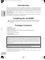
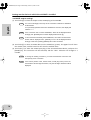
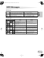
English
mLAN8E
Owner’s manual
Bedienungsanleitung
Deutsch
mLAN EXPANSION BOARD
Français
Mode d’emploi
mLAN8E-(E).book Page 2 Wednesday, October 18, 2000 3:31 PM
FCC INFORMATION (U.S.A.)
1. IMPORTANT NOTICE: DO NOT MODIFY THIS UNIT!
This product, when installed as indicated in the instructions contained in this manual, meets FCC requirements. Modifications not
expressly approved by Yamaha may void your authority, granted
by the FCC, to use the product.
2. IMPORTANT: When connecting this product to accessories and/
or another product use only high quality shielded cables. Cable/s
supplied with this product MUST be used. Follow all installation
instructions. Failure to follow instructions could void your FCC
authorization to use this product in the USA.
3. NOTE: This product has been tested and found to comply with
the requirements listed in FCC Regulations, Part 15 for Class “B”
digital devices. Compliance with these requirements provides a
reasonable level of assurance that your use of this product in a
residential environment will not result in harmful interference with
other electronic devices. This equipment generates/uses radio
frequencies and, if not installed and used according to the instructions found in the users manual, may cause interference harmful
to the operation of other electronic devices. Compliance with FCC
regulations does not guarantee that interference will not occur in
all installations. If this product is found to be the source of interference, which can be determined by turning the unit “OFF” and
“ON”, please try to eliminate the problem by using one of the
following measures:
Relocate either this product or the device that is being affected by
the interference.
Utilize power outlets that are on different branch (circuit breaker
or fuse) circuits or install AC line filter/s.
In the case of radio or TV interference, relocate/reorient the antenna. If the antenna lead-in is 300 ohm ribbon lead, change the
lead-in to co-axial type cable.
If these corrective measures do not produce satisfactory results,
please contact the local retailer authorized to distribute this type
of product. If you can not locate the appropriate retailer, please
contact Yamaha Corporation of America, Electronic Service Division, 6600 Orangethorpe Ave, Buena Park, CA90620
The above statements apply ONLY to those products distributed
by Yamaha Corporation of America or its subsidiaries.
(class B)
* This applies only to products distributed by YAMAHA CORPORATION OF AMERICA.
CANADA
This Class B digital apparatus complies with Canadian ICES-003.
Cet appareil numérique de la classe B est conforme à la norme NMB-003 du Canada.
(class B)
• This applies only to products distributed by Yamaha Canada Music Ltd.
• Ceci ne s’applique qu’aux produits distribués par Yamaha Canada Musique Ltée.
2
mLAN8E-(E).book Page 3 Wednesday, October 18, 2000 3:31 PM
Table of Contents
Introduction ................................................................................... 4
Installing the mLAN8E ................................................................... 4
Features .......................................................................................... 5
Names and Functions..................................................................... 6
Connections.................................................................................... 7
English
Package Contents........................................................................... 4
Internal Configuration of the mLAN8E.......................................... 8
Settings on the device in which the mLAN8E is installed ........... 10
For the A5000/A4000.........................................................................10
For the CS6x/CS6R/S80 .....................................................................15
LED Messages ............................................................................... 21
Specifications................................................................................ 22
3
mLAN8E-(E)TOC.fm Page 4 Wednesday, December 20, 2000 1:52 PM
English
Introduction
Thank you for purchasing the Yamaha mLAN8E. The mLAN8E is an expansion board that
provides an mLAN interface. mLAN is a digital network designed for music and based on the IEEE
1394 high performance serial bus. mLAN makes it easy to construct sophisticated networks for
audio and MIDI signals without having to re-configure the cabling as was necessary with
previous systems.
The mLAN8E includes mixer functionality, and is a powerful enhancement to your music
production system.
In order to take full advantage of the mLAN8E’s functionality, please read this manual carefully.
After reading this manual, keep it for future reference.
Installing the mLAN8E
Installation of the mLAN8E must be performed by one of the qualified Yamaha service personnel or Yamaha dealers listed at the end of the manual of the device in which the mLAN8E is to
be installed.
Package Contents
•
•
•
•
•
•
•
•
mLAN8E unit
mLAN Tools (CD-ROM)
IEEE1394 cable (4.5m)
26-pin flat cable (for connecting mLAN8E and mLAN8E-compatible devices)
Tape (for fastening cables)
Owner’s manual (this document)
mLAN Guide Book
mLAN Tools Installation Guide
About the included CD-ROM
The included CD-ROM contains software that is useful when used in conjunction with the
mLAN8E. The software includes “mLAN Patchbay” which allows audio /MIDI signal routing
between electronic musical instruments connected to the mLAN8E to be controlled from your
computer, and “mLAN Mixer” which allows the mixer/dynamics processor functionality of the
mLAN8E to be controlled from your computer. For details refer to the separate “mLAN Tools
Installation Guide.”
Yamaha cannot be held responsible for damage caused by improper use or
modifications to the instrument, or data that is lost or destroyed.
The illustrations and LCD screens shown in this Owner’s Manual are for instructional purposes only, and
may appear somewhat different from those on your device.
The company names and product names in this Owner’s Manual are the trademarks or registered
trademarks of their respective companies.
4
mLAN8E-(E).book Page 5 Wednesday, October 18, 2000 3:31 PM
Features
mLAN is a digital network designed for music. It uses the IEEE 1394 high performance serial bus,
and allows you to construct systems that are more sophisticated yet simpler than ever before. For
details on mLAN, refer to the separate “mLAN Guidebook.”
■ 16 channel mixer functionality*
English
■ Fast data transfer via mLAN
A 16 channel digital audio mixer is built in.
■ Built-in equalizer / dynamics processor*
A four-band equalizer and dynamics processor provide sophisticated audio control.
* Mixer / equalizer / dynamics processor settings are made using the included “mLAN
Mixer” application. For details refer to the mLAN Mixer manual (electronic manual).
5
mLAN8E-(E).book Page 6 Wednesday, October 18, 2000 3:31 PM
Names and Functions
Rear Panel
3
1
English
2
4
A SERIAL I/O jack
This jack is used to connect the mLAN8E directly to a personal computer via a serial cable. Use this
jack to connect the mLAN8E and the computer when you are using the mLAN Patchbay and mLAN
Mixer on Windows. This is not used to input or output MIDI and audio signals. Refer to page 7 for
more information on the connections.
B mLAN (IEEE1394) jacks
These jacks are used to connect mLAN devices or IEEE1394-compatible devices via IEEE1394 standard (6-pin) cables. Each jack has an LED in the upper left corner to indicate the following statuses.
green : The mLAN8E or connected device is a “leaf” node.
off
: Not connected.
red
: If the cable is disconnected, the sound will be interrupted on a connected device or other
device.
C RT/ERR LED
This LED indicates the following statuses.
green : The mLAN8E is a “root.”
orange : An error has occurred. (IEEE1394 bus-related)
red
: An error has occurred. (Other errors)
off
: Status other than above.
NOTE
Refer to “LED Messages” on page 21 for information on the error indication.
D ACTIVE LED
This LED indicates the following statuses.
blue
: The relay function is active.
off
: The relay function is disabled.
NOTE
6
Since the mLAN8E does not function as a bus relay when the power is turned off, the active
LED also indicates whether the power to the unit is on (blue) or off.
mLAN8E-(E).book Page 7 Wednesday, October 18, 2000 3:31 PM
Connections
Connecting an mLAN (IEEE1394) device
Use an IEEE1394 standard (6-pin) cable to connect the mLAN (IEEE1394) jack on the mLAN
(IEEE1394) device to the mLAN (IEEE1394) jack on the mLAN8E. At this time, you do not have to
turn off the power to either device.
mLAN (IEEE1394) device
CONTRAST
ANALOG
OUT-B
OUT2/R
mLAN8E
DC IN
OUT1/L
COAXIAL
OUT
IN
IN2/R
English
Here’s how to connect the mLAN8E to other mLAN devices or to your computer.
SERIAL I/O
MIDI
OUT-A
IN
IN1/L
mLAN
OPTICAL
OUT
IN
3
IEEE1394 S200
2
1
RT/ERR
ACTIVE
Macintosh computer
that supports FireWire
IEEE1394
standard cable
IEEE1394 standard cable
Connecting a Windows computer (serial connection)
Use a serial cable to connect the computer’s RS232C jack to the mLAN8E’s SERIAL I/O jack. At this
time, make sure that the power to the computer and the device in which the mLAN8E is installed
is turned off.
NOTE
Make this serial connection when using the included software on Windows. To use on a Macintosh, connect the mLAN8E’s mLAN jack and the Macintosh’s FireWire port using an IEEE1394
cable. (See “Connecting an mLAN device.”)
Use a standard D-SUB 9P → MINI DIN 8P cable.
mLAN8E
computer
RS-232C
(DB9)
7
mLAN8E-(E).book Page 8 Wednesday, October 18, 2000 3:31 PM
English
Internal Configuration of the
mLAN8E
mLAN device
mLAN jacks1-3
mLAN
MIDI OUT
mLAN
MIDI IN
mLAN MIDI/
MIDI
conversion
mLAN
audio input*2
MIDI/
mLAN MIDI
conversion
mLAN
audio output
Digital Mixer section*1
mLAN8E
MIDI transmit/
receive section
Source
select
Tone
generator
section
mLAN8Ecompatible
device
MIDI OUT
MIDI IN
MIDI device
8
ANALOG IN
audio device
ANALOG OUT
e.g., mixer,
powered speakers
mLAN signals
mLAN cables
Input
non-mLAN signals
non-mLAN cables
Output
mLAN8E-(E).book Page 9 Wednesday, October 18, 2000 3:31 PM
mLAN plugs (in Mixer mode)
mLAN output plugs (Indicated in the
“From” field in mLAN Patchbay.)
mLAN audio
mLAN input plugs (Indicated in the
“To” field in mLAN Patchbay.)
Mix L (stereo mix L)
Mix R (Stereo mix R)
AUX1
AUX2
AUX3
AUX4
AUX5
AUX6
CH9
CH10
CH11
CH12
CH13
CH14
CH15
CH16
mLAN MIDI
MIDI OUT
English
Internal Configuration of the mLAN8E
mLAN audio
mLAN MIDI
MIDI IN
NOTE
In Direct mode, the number and names of plugs displayed will differ according to the
device in which the mLAN8E is installed (page 22).
NOTE
There are no mLAN input plugs corresponding to the A/D INPUT of the CS6x/CS6R/S80.
The diagram on the left illustrates the entire signal flow.
The mLAN8E has 16-channel digital mixer functionality, and can mix mLAN audio signals with audio
signals produced by the device that contains the mLAN8E.
The input/output destinations of these signals and the mixer functionality can be easily controlled
from your computer by using the included mLAN Tools.
NOTE
The mLAN8E mixer section features Direct mode and Mixer mode. When the mLAN Mixer is
not being used, the unit is in Direct mode, in which signals are input and output directly. When
mLAN Mixer is being used, the unit enters Mixer mode. The default setting (when you turn on
the power to the unit) is Direct mode. If you turn the power to the device off, then on while
mLAN Mixer is running, restart mLAN Mixer.
*1 The included mLAN Mixer application is required in order to make digital mixer settings. For details on
the structure of the digital mixer section, refer to the block diagram of the mLAN Mixer manual.
*2 For mLAN audio inputs, you can select from any 8 channels on the bus (system).
9
mLAN8E-(E).book Page 10 Wednesday, October 18, 2000 3:31 PM
English
Settings on the device in which
the mLAN8E is installed
For the A5000/A4000
If the mLAN8E is installed in the A5000/A4000, you will be able to make mLAN-related settings.
mLAN settings are made in Utility mode.
NOTE
In order to use mLAN, you must first access the mLAN Configuration page
and set MIDI Input to a setting other than MIDI IN.
mLAN Cnct (mLAN connections)
NOTE
mLAN connections tone generators are saved in the mLAN8E. They cannot
be saved on disk.
Cursor 1 Out (output)
■ Knob 1
[
turn] Move cursor / switch pages
Move the cursor or switch pages.
[ press] Tree View
Access the Tree View screen.
■ Knob 2
[
turn] Out (select output plug)
Select the mLAN plug of the mLAN8E that will be the output source.
❑ Setting: AS (assignable) 1~6, DIG-L, DIG-R, MIDI
10
mLAN8E-(E).book Page 11 Wednesday, October 18, 2000 3:31 PM
Settings on the device in which the mLAN8E is installed
[
turn] Connect# (select connection number of the connected mLAN device)
Select the connection number of the connected mLAN device. In the case of numbers for
which a connection has already been made, the module name and plug name will be displayed in parentheses. If there are fewer than 62 connections, you can select “New” and create a new connection (mLAN input plug).
❑ Setting: 1~62, New
[ press] mLAN_INIT (mLAN initialize)
Initialize mLAN-related settings. This will be executed after you reply to a confirmation dialog
box.
All connection settings will be set to “---”. The Word Clock Mode will be “Auto.”
NOTE
English
■ Knob 3
The Nickname settings will not be initialized.
■ Knob 4
[
turn] Module (select connected module)
Select an mLAN device on the mLAN bus (system). When you select a valid mLAN device, the
top line will show the vendor name and the Nickname.
NOTE
Settings cannot be modified for the connection number of an already-established connection.
■ Knob 5
[
turn] Plug (select connected mLAN plug)
Select the mLAN input plug of the connected mLAN device.
NOTE
The connection is executed by CONNECT (press knob 5). If after making
your selection, you change pages, move the cursor, or change the Out or
Connect# settings without executing CONNECT, the selected value will be
cleared.
NOTE
If there are no plugs that can be selected, this will be displayed as “---.”
[ press] CONNECT
Connect to the mLAN input plug of the selected mLAN device.
If the connection number is “New,” this function will appear if you have selected a module
name or plug name that can be connected.
[ press] CUT (disconnect)
Break the selected connection.
This function will appear if you have selected an already-connected module name / plug
name.
11
mLAN8E-(E).book Page 12 Wednesday, October 18, 2000 3:31 PM
Settings on the device in which the mLAN8E is installed
Cursor 2 In (input)
■ Knob 1
English
[
turn] Move cursor / switch pages
Move the cursor or switch pages.
[ press] Tree View
Access the Tree View screen.
■ Knob 2
[
turn] In (select input plug)
Select the mLAN8E mLAN plug that will input the signal. If a connection has already been
made, the module name and plug name will be displayed in parentheses.
❑ Setting: AD-L, AD-R, MIDI
■ Knob 3
Display only
If unconnected, this will indicate “New.”
[ press] mLAN_INIT (mLAN initialize)
Initialize mLAN-related settings. This will be executed after you reply to a confirmation dialog
box.
All connection settings will be set to “---”. The Word Clock Mode will be “Auto.”
NOTE
The Nickname settings will not be initialized.
■ Knob 4
[
turn] Select connected module
Select an mLAN device on the mLAN bus (system). When you select a valid mLAN device, the
top line will show the vendor name and the Nickname.
■ Knob 5
[
turn] Select connected mLAN plug
Select an mLAN output plug on the connected mLAN device.
NOTE
The connection is executed by CONNECT (press knob 5). If after making
your selection, you change pages, move the cursor, or change the Out or
Connect# settings without executing CONNECT, the selected value will be
cleared.
NOTE
If there are no plugs that can be selected, this will be displayed as “---.”
[ press] CONNECT
Connect to the mLAN output plug of the selected mLAN device.
If the node number is “New,” this function will appear if you have selected a module name or
plug name that can be connected.
[ press] CUT (disconnect)
Break the selected connection.
This function will appear if you have selected an already-connected module name or plug
name.
12
mLAN8E-(E).book Page 13 Tuesday, June 26, 2001 5:42 PM
Settings on the device in which the mLAN8E is installed
English
mLAN Cnfg (mLAN configuration)
NOTE
Output Level Offset, Word Clock Mode, and Nickname settings are saved in
the mLAN8E. They cannot be saved on disk.
Cursor 1
■ Knob 1
[
turn] Move cursor / switch pages
Move the cursor or switch pages.
[ press] Tree View
Access the Tree View screen.
■ Knob 2
[
turn] Output Level Offset
Specify the output volume (offset value) for all mLAN audio outputs.
❑ Setting: +0 dB ~ +24 dB
■ Knob 4
[
turn] Audio Input (audio input select)
Select the audio input source.
❑ Setting
ADIn:
mLAN:
Use two analog audio channels from the INPUT jacks of the A5000/A4000.
Use two mLAN audio channels. The audio signals from the INPUT jacks of the A5000/
A4000 will not be input.
Cursor 2
■ Knob 1
[
turn] Move cursor / switch pages
Move the cursor or switch pages.
[ press] Tree View
Access the Tree View screen.
■ Knob 3
[
turn] Word Clock Mode
Specify the word clock.
❑ Setting
Auto:
The word clock of the audio output will automatically synchronize to an 44.1 kHz external
device. The A5000/A4000 may function as the master in some cases, or as the slave in
other cases.
Group1Master (44.1 kHz): The A5000/A4000 will function as a 44.1 kHz master device.
13
mLAN8E-(E).book Page 14 Wednesday, October 18, 2000 3:31 PM
Settings on the device in which the mLAN8E is installed
Before the Word Clock Mode is selected or after SET is executed, this will indicate the current
Word Clock Mode. The display has the following significance.
English
•
•
•
•
Auto(Int): Operating in Auto Mode on the internal clock
Auto(Ext): Operating in Auto Mode as a slave
---(Int): Operating in Manual Mode on the internal clock
---(Ext): Operating in Manual mode as a slave
[ press] SET (finalize word clock)
Finalize the selected Word Clock Mode setting.
■ Knob 4
Nickname (display only)
Displays the Nickname of the A5000/A4000.
[ press] Rename
Set the Nickname.
■ Knob 5
[
turn] MIDI Input (MIDI Input selection)
NOTE
Regardless of this setting, the same MIDI output data is sent from both MIDI
OUT and mLAN MIDI.
NOTE
Regardless of this setting, the MIDI THRU connector will re-transmit the data
that was input to MIDI IN.
❑ Setting
MIDI IN:
MIDI messages input from the MIDI IN connectors will play the A5000/A4000; mLAN will
not be used.
mLAN->A: MIDI messages from the mLAN MIDI input will be sent to the MIDI IN-A port. MIDI messages from the rear panel MIDI IN-A connector will not be input (A5000 only).
mLAN->B: MIDI messages from the mLAN MIDI input will be sent to the MIDI IN-B port. MIDI messages from the rear panel MIDI IN-B connector will not be input (A5000 only).
mLAN:
14
MIDI messages from the mLAN MIDI input will be input to the MIDI IN port. MIDI messages from the rear panel MIDI IN connector will not be input (A4000 only).
mLAN8E-(E).book Page 15 Wednesday, October 18, 2000 3:31 PM
Settings on the device in which the mLAN8E is installed
If the mLAN8E is installed in the CS6x/CS6R/S80, you will be able to make mLAN-related settings.
mLAN settings are made mainly in Utility mode.
MIDI settings
1 Press the [UTILITY] key to enter Utility mode.
English
For the CS6x/CS6R/S80
2 Turn the [PAGE] knob to access the “MIDI Other” page.
MIDI Other) In ThruPort
Sys
MIDI
1
SHIFT
PAGE
A
B
C
Sync SeqCtrl
int
on
1
2
DATA
PART/ELEMENT
3 Use knob [B] to set “In” to “mLAN.”
MIDI Other) In ThruPort
Sys
mLAN
1
SHIFT
PAGE
A
B
C
Sync SeqCtrl
int
on
1
2
DATA
PART/ELEMENT
15
mLAN8E-(E).book Page 16 Wednesday, October 18, 2000 3:31 PM
Settings on the device in which the mLAN8E is installed
MIDI Other
An CS6x/CS6R/S80 in which the mLAN8E is installed will have the following additional functions.
English
MIDI Other) In ThruPort
Sys
mLAN
1
Sync SeqCtrl
int
on
■ In (MIDI Input)
Select whether to use the MIDI connector or the mLAN connector as the input route for MIDI
messages. If you select “mLAN,” the HOST SELECT switch will have no effect, and MIDI messages from devices connected to the TO HOST connector or MIDI IN connector will not be
input.
❑ Setting: MIDI, mLAN
NOTE
Regardless of this setting, MIDI OUT messages will be output both from the
MIDI OUT connector and the mLAN connector.
NOTE
If you select mLAN, MIDI OUT messages will not be output from TO HOST.
NOTE
If you select mLAN, the ThruPort setting will have no effect.
■ Sync (when the above MIDI Input = mLAN)
When playing in synchronization with an external device, specify whether the CS6x/CS6R/S80
will operate using its own internal clock or the MIDI Clock received via the mLAN connector. If
you select “Int (internal),” the CS6x/CS6R/S80 will operate using its own internal clock. Select
this when using the CS6x/CS6R/S80 by itself or as the master of a synchronized performance
using MIDI Clock. If you select “MIDI,” the CS6x/CS6R/S80 will operate according to the
MIDI Clock received via the mLAN connector. Select this when using the CS6x/CS6R/S80 as a
slave of a synchronized performance using MIDI Clock.
❑ Setting: MIDI, int (internal)
■ SeqCtrl (Sequence Control) (when the above MIDI Input = mLAN)
Specify whether or not you wish to transmit and receive the mLAN MIDI messages Start, Stop,
and Continue. This is also a switch for outputting MIDI Clock from mLAN MIDI output.
❑ Setting: off (don’t transmit or receive), on (transmit and receive)
16
mLAN8E-(E).book Page 17 Tuesday, June 26, 2001 5:43 PM
Settings on the device in which the mLAN8E is installed
mLAN Connection, Word Clock, and Nickname settings
The method of entering each page is the same as for MIDI Setting. In Utility
mode, turn the [PAGE] knob to display the desired page. (Page 15)
English
NOTE
mLAN Connect (mLAN connection)
3
mLAN Connect)YAMAHA
MIDI OUT->New:S80
1
SHIFT
PAGE
2 5
A
4
8
:Vivien
MIDI-IN
[ENTER]
toCnct
6
B
7
C
1
2
DATA
PART/ELEMENT
A mLAN plug of the mLAN8E
NOTE
The number of plugs and their names will differ depending on the device in
which the mLAN8E is installed.
B This indicates an input setting (<-) or output setting (->). In the example
shown above, the MIDI OUT plug of the mLAN8E is being connected to an
external S80 (Nickname=Vivien).
C Vendor name of connected device
D Nickname of connected device
E Connection number of connected device
F Module name of connected device
G mLAN plug name of connected device
H Connect/disconnect
[ENTER] toCnct ... press the [ENTER] key to connect
[ENTER] toCut ... press the [ENTER] key to disconnect
17
mLAN8E-(E).book Page 18 Wednesday, October 18, 2000 3:31 PM
Settings on the device in which the mLAN8E is installed
• mLAN8E output settings
English
(1) Turn knob [A] to select the output source mLAN plug of the mLAN8E.
NOTE
You can turn knob [B] to check up to 62 Connection numbers for destination
mLAN devices.
If no previously-specified connection destinations are found, the display will
indicate “*****”.
NOTE
If the connection has not been established, “New” will be displayed above
knob [B], and “[ENTER] toCnct” will be displayed above knob [2].
NOTE
If the connection has already been established, the current connection destination will be displayed. Also, “[ENTER] To Cut” will be displayed above
knob [2]. In this case, pressing [ENTER] will cut the connection.
(2) Turn knob [C] to select an mLAN device on the mLAN bus (system). The upper line will show
the vendor name, and the lower line will show the module name.
(3) Turn knob [1] to select the mLAN input plug of the connected mLAN device, and press the
[ENTER] key. The connection will be executed, and the “New” indication will change to a
number.
18
NOTE
To change an existing connection, you must first break the connection and
then specify a new connection.
NOTE
If the names (vendor name, module name, mLAN plug name) of the connected device exceed eight characters, only the first eight characters will be
displayed.
mLAN8E-(E).book Page 19 Wednesday, October 18, 2000 3:31 PM
Settings on the device in which the mLAN8E is installed
• mLAN8E input settings
An mLAN input plug of the mLAN8E can have only one connection.
(1) Turn knob [A] to select the mLAN8E mLAN plug that will input the signal. The module name
and plug name for the destination device will be displayed as “-----”.
NOTE
If a connection has already been established, the current connection destination will be displayed. Also, the display will indicate “[ENTER] To Cut”
above knob 2. In this case, press [ENTER] to break that connection.
English
NOTE
(2) Turn knob [C] to select an mLAN device on the mLAN bus (system). The upper line will show
the vendor name, and the lower line will light the module name.
(3) Turn knob [1] to select an mLAN input plug on the destination mLAN device, and press
[ENTER] to execute the connection.
NOTE
To change an existing connection, you must first break the connection and
then specify a new connection.
NOTE
If the names (vendor name, module name, mLAN plug name) of the connected device exceed eight characters, only the first eight characters will be
displayed.
NOTE
mLAN connections tone generators are saved in the mLAN8E. They cannot
be saved on a memory card.
mLAN Word Clock
Select the Word Clock.
mLAN WordClock)
Mode
[ENTER]
Sys
Group1Master(44.1kHz) to Set
■ Mode
Select whether the CS6x/CS6R/S80 will function as the Word Clock Master (Group 1 Master)
of the connected mLAN Audio network, or whether the slave/master setting will be selected
automatically (auto). When you select the Mode and press [ENTER], a confirmation screen will
appear. To execute the setting press [YES]. To cancel press [NO]. When the setting has been
finalized, the display will indicate “(int)” or “(ext=********)” at the right of Mode. “(int)” indicates that the CS6x/CS6R/S80 in which the mLAN8E is installed is acting as the word clock
master. “(ext=********)” indicates that it is acting as the slave of an external module named
“********”.
❑ Setting: auto (44.1 kHz), Group1Master (44.1 kHz)
NOTE
This setting is stored in the mLAN8E. It cannot be saved on a memory card.
19
mLAN8E-(E).book Page 20 Wednesday, October 18, 2000 3:31 PM
Settings on the device in which the mLAN8E is installed
mLAN initialize
This initializes the mLAN connection and word clock settings of the mLAN8E installed in the
CS6x/CS6R/S80. When you press [ENTER], a confirmation screen will appear. Press [YES] to exe-
English
cute the initialization, or press [NO] to cancel.
mLAN Initialize)
Sys
NOTE
[ENTER]
to Init
The Nickname settings will not be initialized.
mLAN Nickname
Specify the nickname of the CS6x/CS6R/S80 in which the mLAN8E is installed. The input procedure is the same as when inputting a CS6x/CS6R/S80 voice name.
After inputting the name, press [ENTER] to finalize it.
mLAN Nickname)
Sys
a-Z
0-? Cursor
[Vivien ]
Other mLAN-related settings
• Voice mode
For OSC Pan (oscillator pan) Output, you will be able to specify ind3~ind6.
• Performance mode
For LYR Out (layer out) Output, you will be able to specify ind3~ind6.
• Phrase Clip mode (CS6x/CS6R)
For OSC Pan (oscillator pan) Output, you will be able to specify ind3--ind6.
20
mLAN8E-(E).book Page 21 Wednesday, October 18, 2000 3:31 PM
LED Messages
LED messages
Status
mLAN1–3
RT/ERR
Indicates root and error.
Red/orange ... An error has occurred.
Green ... The mLAN8E is a “root.”
ACTIVE
Indicates the status of the relay function.
Blue ... The relay function is enabled.
English
Function
Indicates if sound from sources other than the Red ... Sound is interrupted.
device being disconnected is interrupted.
Green ... Sound is not interrupted. (leaf node)
Error messages
3
2
1
red
green
red
red
Cause
The topology of the connected
devices creates a loop.
Cycle Start Packet is not transmitted
orange to the bus. (Audio/MIDI data cannot
be transmitted.)
A malfunctioning device exists on the
red
orange
bus.
green orange The number of hops exceeds 16.
red
red
RT
orange
Action
Check to see if any part of the connection creates a loop.
Remove the malfunctioning device.
Remove the malfunctioning device.
Check the number of hops.
Add a power provider to the bus, or
orange The power to the bus is insufficient.
remove a power consumer from the
bus.
red MIDI IN transfer rate is not correct.
Check the MIDI transfer rate setting.
Data transmission exceeds the MIDI
Check to see if the transmitting
red
transfer rate.
device is operating properly.
The sound is interrupted for some rea- Check the word clock setting on the
red
son, or the devices are not syncing.
mLAN8E and the source.
21
mLAN8E-(E).book Page 22 Wednesday, October 18, 2000 3:31 PM
English
Specifications
mLAN
IEEE1394 High Performance Serial Bus
Data Rate S200, Isochronous Resource Manager capable, Bus Manager capable, Connection Manager
Conforms to IEC61883-6 Audio and Music Protocol
Digital Audio 8in/8out, MIDI 1in/1out
Sampling rate
44.1kHz
Functions
Direct Mode
Input: 2 (max), Output: 8 (max)
Mixer Mode
Input: 16 (max) Link, Gain, ATT, Phase, EQ (4Band)*, Dynamics*, AUX Send
(x6), Pre/Post (x6), Channel on/off, Meter, Pan, Fader
Output: 8 (max) Level, Balance, AUX Link, AUX Master (x6)
* Up to eight channels
Jacks
mLAN IEEE1394 (1, 2, 3), SERIAL I/O
mLAN plugs
Direct mode
A5000/A4000
AS1–6 OUT, DG-L OUT, DG-R OUT, AD-L IN, AD-R IN,
MIDI OUT, MIDI IN
CS6x/CS6R/S80
IND1–6 OUT, L OUT, R OUT, MIDI OUT, MIDI IN
Mixer mode
NOTE
Mix L, Mix R, AUX1–6, CH9–16, MIDI OUT, MIDI IN
For more information, refer to “mLAN plugs (in Mixer mode)”
on page 9.
Display
Rear panel: mLAN 1/2/3 LED, ACTIVE LED, RT (Root)/ERR (Error) LED
Power consumption 4 W
Specifications and descriptions in this owner’s manual are for information purposes only. Yamaha Corp. reserves the right
to change or modify products or specifications at any time without prior notice.Since specifications, equipment or options
may not be the same in every locale, please check with your Yamaha dealer.
22
8E-Hyo4.fm Page 23 Wednesday, December 20, 2000 1:49 PM
Yamaha Manual Library (English versions only)
http://www2.yamaha.co.jp/manual/english/
This document is printed on recycled chlorine free
(ECF) paper with soy ink.
Auf Recycling-Umweltpapier gedruckt.
Ce document a été imprimé sur du papier recyclé non
blanchi au chlore.
M.D.G.,Pro Audio & Digital Musical Instrument Division, Yamaha Corporation
© 2000 Yamaha Corporation
V485680 010APAP2.2-02B0 Printed in Japan