1
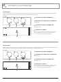
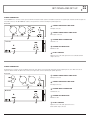
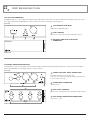
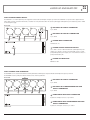
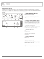
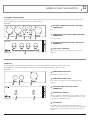
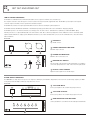
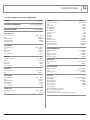
INSTALLATION AND OPERATION MANUAL
AUDIO CONTRACTOR
TOOLS
LET’S SPLIT (L) • LET’S SPLIT (M)
GET DOWN • GET UP
DROP ME • MULTI CAN
JUICED UP • BUZZ OFF
PRE ME • MIXED UP
THE INJECTOR • GET OUT
ZONED OUT
IMPORTANT SAFETY INFORMATION
PRÉCAUTIONS DURANT UTILISATION
1. Read these instructions.
1. LISEZ ces instructions.
2. Keep these instructions.
2. Tenez ces instructions.
3. Heed all warnings.
3. Notez tous les avertissements.
4. Follow all instructions.
4. Suivez toutes les avertissements.
5. Do not use this apparatus near water.
5. N’utilisez pas ce produit près de l’eau (la piscine, la plage, le lac, etc.).
6. Clean only with dry cloth.
6. Nettoyez seulement avec une étoffe sèche.
7. Do not block any ventilation openings. Install in accordance with the
manufacturer’s instructions.
7. Ne bloquez aucuns troux de ventilation. Installez en accord avec les
instructions du manufacturier.
8. Do not install near any heat sources such as radiators, heat registers,
stoves, or other apparatus (including amplifiers) that produce heat.
8. N’installez près aucunes sources de chaleur comme radiateurs, registres
de chaleur, fours ou les autres équipements (y compris amplificateurs) qui
produisent la chaleur.
9. Do not defeat the safety purpose of the polarized or grounding-type
plug. A polarized plug has two blades with one wider than the other. A
grounding type plug has two blades and a third grounding prong. The wide
blade or the third prong are provided for your safety. If the provided plug
does not fit into your outlet, consult an electrician for replacement of the
obsolete outlet.
10. Protect the power cord from being walked on or pinched particularly
at plugs, convenience receptacles, and the point where they exit from
the apparatus.
11. Only use attachments/accessories specified by the manufacturer.
12. Use only with the cart, stand, tripod, bracket, or table specified by the
manufacturer, or sold with the apparatus. When a cart is used, use caution
when moving the cart/apparatus combination to avoid injury from tip-over.
13. Unplug this apparatus during lightning storms or when unused for long
periods of time.
14. Refer all servicing to qualified service personnel.
Servicing is required when the apparatus has been
damaged in any way, such as power-supply cord or plug
is damaged, liquid has been spilled or objects have fallen
into the apparatus, the apparatus has been exposed to
rain or moisture, does not operate normally, or has been
dropped.
15. This appliance shall not be exposed to dripping or splashing water and
that no object filled with liquid such as vases shall be placed on the
apparatus.
16. Plug this apparatus to the proper wall outlet and make the plug to be
disconnected readily operable.
17. Mains plug is used as disconnected device and it should remain readily
operable during intended use. In order to disconnect the apparatus from
the mains completely, the mains plug should be disconnected from the
mains socket outlet completely.
9. Ne défaites pas le but de sécurité de la fiche polarisée ou base-type. Une
fiche polarisée a deux tranchants avec un plus large que l’autre. Une fiche
de base type a deux a deux tranchants et une troisième pointe de base,
le tranchant large ou la troisième pointe est fourni pour votre sécurité. Si
la fiche donnée ne conforme pas votre prise de contact, consultez un
électricien pour remplacement de la prise de contact obsolète.
10. Protegez le cordon de secteur contre être marchée dessus ou pincez en
particulier aux fiches, aux douilles de convenance, et au point où ils
sortent de l’appareil.
11. Seulement utilisez attachements/accessoires spécifiés par le manufacturier.
12. Utilisez seulement avec un chariot, un stand, un trépied, un support ou
une table indiquée par le manufacturier, ou vendue avec l’appareil. Quand
un chariot est utilisé, faites attention en déplaçant la combinaison
d’appareil/chariot pour éviter de se déséquilibrer.
13. Arrachez la fiche du dispositif durant éclair et orage ou quand pas utilisé
pour longues périodes de temps.
14. Référez au personnel qualifié de service pour toutes
réparations. La réparation est donnée quand le système
a été endommagé à n’importe façon, par exemple un fil
ou une fiche endommagé(e) de la source d’alimentation.
Avoir été exposé à pluie ou humidité, n’opère pas
normalement, ou avoir été tombé.
15. L’appareil ne doit pas être exposé aux écoulements ou aux éclaboussures
et aucun objet ne contenant de liquide, tel qu’un vase, ne doit être placé
sur l’objet.
16. Branchez l’appareil à une source appropriée et faire que la prise à
débrancher soit facilement accessible.
17. La prise du secteur ne doit pas être obstruée ou doit être facilement
accessible pendant son utilisation. Pour être complètement déconnecté
de l’alimentation d’entrée, la prise doit être débranchée du secteur.
18. WARNING: To reduce the risk of fire or electric shock, do not expose this
apparatus to rain or moisture.
18. AVERTISSEMENT: Pour éviter le risque d’incendie ou de chocs électriques,
ne pas exposer cet appareil à la pluie ou à l’humidité.
19. An appliance with a protective earth terminal should be connected to a
mains outlet with a protective earth connection.
19. Un appareil avec la borne de terre de protection doit être connecté au
secteur avec la connexiion de terre de protection.
20. The apparatus should be disconnected from the mains completely before
speaker wiring. The speaker output should be proper protected from
direct contact and pay attention to speaker connections, terminals and
speaker wiring during normal operation.
20. Assurez-vous que l’appareil est hors tension avant de connecter les hauts
parleurs. Verifiez que la sortie des enceintes soit protégées contre un
contact physique. Respecter les polarités des terminaux ainsi que le
câblage des enceintes pendant le fonctionnement afin d’assurer une
utilisation sécurisee.
PAGE 2
AUDIO CONTRACTOR TOOLS INSTALLATION AND OPERATION MANUAL
INTRODUCTION AND CONTENTS
AUDIO CONTRACTOR TOOLS
INTRODUCTION3
Since their introduction the contractor tool range has proved
immensely popular with AV installers all around the world.
LET’S SPLIT (L) & LET’S SPLIT (M)
4
GET DOWN AND GET UP
5
DROP ME AND MULTI CAN
6
JUICED UP AND BUZZ OFF
7
PRE ME
8
MIXED UP AND THE INJECTOR
9
The entire range of audio contractor tools has been redesigned &
expanded to provide even more useful solutions for audio contractors
the world over.
NOW RACKMOUNTABLE (Up to three audio contractor tools per
1RU shelf)
GET OUT AND ZONED OUT
10
SPECIFICATIONS11
AUS, EUR, USA
REV B: SEP 2014
WARNING!
TO PREVENT FIRE OR SHOCK HAZARD, DO NOT USE THE PLUG WITH
AN EXTENSION CORD, RECEPTACLE OR OTHER OUTLET UNLESS THE BLADES
CAN BE FULLY INSERTED TO PREVENT BLADE EXPOSURE.
TO REDUCE THE RISK OF FIRE OR ELECTRIC SHOCK, DO NOT EXPOSE
THIS APPLIANCE TO RAIN OR MOISTURE.
TO PREVENT ELECTRICAL SHOCK, MATCH WIDE BLADE PLUG TO WIDE SLOT & FULLY INSERT.
CAUTION
THESE SERVICING INSTRUCTIONS ARE FOR USE BY QUALIFIED SERVICE PERSONNEL ONLY.
TO REDUCE THE RISK OF ELECTRIC SHOCK DO NOT PERFORM ANY SERVICING OTHER THAN THAT
CONTAINED IN THE OPERATING INSTRUCTIONS UNLESS YOU ARE QUALIFIED TO DO SO.
CAUTION
RISK OF ELECTRIC SHOCK
DO NOT OPEN
The lightning flash with
arrowhead symbol, within an
equilateral triangle, is intended to
alert the user to the presence of
uninsulated “dangerous voltage”
within the product’s enclosure
that may be of sufficient
magnitude to constitute a risk
of electric shock to persons.
WARNING:
TO REDUCE THE RISK OF
ELECTRIC SHOCK, DO NOT
REMOVE COVER (OR BACK).
NO USER SERVICEABLE PARTS
INSIDE. REFER SERVICING
TO QUALIFIED SERVICE
PERSONNEL.
The exclamation point within
an equilateral triangle is
intended to alert the user to
the presence of important
operating and maintenance
(servicing) instructions in the
literature accompanying the
appliance.
For European Union countries: This symbol on
the product or its packaging indicates that this
product must not be disposed of with other waste.
Instead, it is your responsibility to dispose of your
waste equipment by handing it over to a designated
collection point for the recycling of waste electrical
and electronic equipment.
Please contact your local authority for further details
of your nearest designated collection point.
Rating plate and caution marking are marked on the back enclosure of the apparatus
AUDIO CONTRACTOR TOOLS INSTALLATION AND OPERATION MANUAL
PAGE 3
LET’S SPLIT (L) & LET’S SPLIT (M)
LINE SPLITTER
The LETS SPLIT (L) is a balanced line level splitter with a balanced XLR line level input which provides both a transformer balanced XLR output & a thru (direct) XLR
output of the input signal. The LETS SPLIT (L) also provides a ground lift switch to eliminate ground loop hum.
REAR PANEL
1 BALANCED XLR INPUT CONNECTOR
2 BALANCED XLR THRU OUTPUT CONNECTOR
Parallel to input
1
2
3
3 BALANCED XLR OUTPUT CONNECTOR
Transformer isolated
4 GROUND LIFT SWITCH
Pin1 lift on transformer isolated XLR output Set to “GND” to connect
pin 1 of output XLR connector to pin 1 of input XLR connectors.
Set to “Lift” to disconnect pin1 output XLR connector
FRONT PANEL
4
LINE SPLITTER
The LETS SPLIT (M) is a balanced microphone level splitter with a balanced XLR microphone level input which provides both a transformer balanced XLR output & a thru
(direct) XLR output of the input signal. The LETS SPLIT (M) also provides a ground lift switch to eliminate ground loop hum.
REAR PANEL
1 BALANCED XLR INPUT CONNECTOR
2 BALANCED XLR THRU OUTPUT CONNECTOR
Parallel to input
1
2
3
3 BALANCED XLR OUTPUT CONNECTOR
Transformer isolated
4 GROUND LIFT SWITCH
Pin1 lift on transformer isolated XLR output Set to “GND” to connect
pin 1 of output XLR connector to pin 1 of input XLR connectors.
Set to “Lift” to disconnect pin1 output XLR connector
FRONT PANEL
PAGE 4
4
AUDIO CONTRACTOR TOOLS INSTALLATION AND OPERATION MANUAL
GET DOWN AND GET UP
STEREO CONVERTER
The GET DOWN stereo converter converts a professional line level balanced audio signal to an unbalanced domestic level signal. Inputs are balanced XLRs & outputs are
stereo RCA connectors. The GET DOWN also features a front panel level control for achieving the optimal output level.
REAR PANEL
1 STEREO BALANCED LINE LEVEL
XLR input connectors
2 STEREO UNBALANCED LINE LEVEL
RCA output connectorst
1
2
3
3 POWER INPUT CONNECTOR
DC Centre +ve
4 POWER LED INDICATOR
Illuminated = On
FRONT PANEL
4
5
5 LEVEL CONTROL
Adjusts the level of the audio signal on the stereo unbalanced RCA
output connectors
STEREO CONVERTER
The GET UP stereo converter converts an unbalanced domestic level signal to a professional line level balanced audio signal. Inputs are stereo RCA connectors &
outputs are balanced XLR’s. The GET UP also features a front panel level control for achieving the optimal output level.
REAR PANEL
1 STEREO UNBALANCED LINE LEVEL
RCA input connectors
2 STEREO BALANCED LINE LEVEL
XLR output connectors
1
2
3
3 POWER INPUT CONNECTOR
15VDC Centre +ve
4 POWER LED INDICATOR
Illuminated = On
FRONT PANEL
4
5
5 LEVEL CONTROL
Adjusts the level of the audio signal on the stereo
balanced XLR output connectors
AUDIO CONTRACTOR TOOLS INSTALLATION AND OPERATION MANUAL
PAGE 5
DROP ME AND MULTI CAN
100 VOLT LINE CONVERTER
The DROP ME allows you to convert a 100 volt line amplifier speaker output signal to a balanced line level signal. The 100 volt line signal input is via phoenix connector
& the output is balanced XLR. The DROP ME also features a rear panel level control for achieving the optimal output level
REAR PANEL
1 100V SPEAKER LINE INPUT
WECO connector with parallel output
2 LEVEL CONTROL
Adjusts the level of the audio signal on the XLR output connector
1
2
3
3 BALANCED LINE LEVEL XLR OUTPUT
CONNECTOR
FRONT PANEL
4 CHANNEL HEADPHONE AMPLIFIER
The MULTI CAN is a compact yet high quality 4 channel headphone amplifier, featuring 6.35mm TRS, dual RCA & dual XLR stereo inputs & 6.35mm TRS headphone
outputs. The MULTI CAN also offers individual output level controls per channel.
REAR PANEL
1 STEREO LINE LEVEL INPUT CONNECTORS
In parallel (6.35mm TRS stereo jack, stereo RCA
connectors, stereo XLR connectors) All four headphone amplifiers share
the same common stereo input
2 POWER INPUT CONNECTOR
1
2
3
15VDC Centre +ve
3 FOUR LEVEL CONTROLS
Adjusts the level of the audio signal of the headphone jack directly below
4 FOUR STEREO HEADPHONE CONNECTORS
6.35mm stereo sockets
FRONT PANEL
PAGE 6
4
AUDIO CONTRACTOR TOOLS INSTALLATION AND OPERATION MANUAL
JUICED UP AND BUZZ OFF
DUAL PHANTOM POWER SUPPLY
The JUICED UP is a 2 channel phantom power supply that features balanced XLR inputs & outputs per channel. The JUICED UP can operate via the supplied external
power supply or via two on board 9 volt batteries, selectable via a rear panel slider switch. The Juiced up will supply 15VDC phantom power via battery power & 42VDC
off external power supply
REAR PANEL
1 BALANCED XLR INPUT CONNECTOR
1 per channel
2 BALANCED XLR OUTPUT CONNECTOR
1 per channel
2
1
2
1
4
3
3 POWER INPUT CONNECTOR
15VDC Centre +ve
4 POWER SOURCE SELECTION SWITCH.
FRONT PANEL
Set to “Batt” to run off 2x 9V internal batteries (15VDC phantom power
output). Set to “PPack” to run off an external 15VDC (centre +ve) plug
pack (42VDC phantom power output). Set to “PPack” when not in use to
prolong internal battery life.
5
5 POWER LED INDICATOR
Illuminated = On
DUAL CHANNEL HUM ELIMINATOR
The BUZZ OFF is a two channel hum eliminator featuring both balanced XLR inputs & outputs & unbalanced RCA inputs & outputs per channel.
The BUZZ OFF is ideal or getting rid of hum & extraneous noise from long cable runs.
3
REAR PANEL
1 BALANCED XLR INPUT CONNECTOR
1 per channel
2 BALANCED XLR TRANSFORMER ISOLATED
OUTPUT CONNECTOR
1 per channel
1
2
4
1
2
3 UNBALANCED RCA INPUT CONNECTOR
In parallel to XLR input connector, 1 per channel
4 UNBALANCED RCA TRANSFORMER ISOLATED
OUTPUT CONNECTOR
FRONT PANEL
AUDIO CONTRACTOR TOOLS INSTALLATION AND OPERATION MANUAL
In parallel to XLR output connector, 1 per channel
PAGE 7
PRE ME
MICROPHONE PRE AMPLIFIER
The PRE ME is a compact yet highly featured microphone pre amplifier. The PRE ME features dual RCA line input & a balanced XLR input switchable between
microphone & line level. The PRE ME also offers +40VDC phantom power, switchable High pass filter (rolling off at dB per octave at 100 Hz & balanced XLR output.
A front panel gain control & dual colour signal present LED are also offered for ease of setup & operation
REAR PANEL
1 STEREO UNBALANCED LINE LEVEL
RCA input connectors (mono summed)
2 BALANCED MICROPHONE/LINE LEVEL
XLR input connector
1
2
3
4
5
6
3 XLR INPUT CONNECTOR MODE SWITCH.
Set to “+40V MIC” to set the XLR input connector sensitivity to
microphone level with phantom power enabled. Set to “MIC” to
set the XLR input connector sensitivity to microphone level. Set
to “LINE” to set the XLR input connector sensitivity to line level
FRONT PANEL
4 HIGH PASS FILTER SWITCH.
7
8
9
Set to “100Hz” to enable the 100Hz high pass filter on all inputs.
Set to “Off” to disable the high pass filter on all inputs
5 BALANCED LINE LEVEL
XLR output connector
6 POWER INPUT CONNECTOR
15VDC Centre +ve
7 POWER LED INDICATOR
Illuminated = On
8 SIGNAL PRESENCE LED.
Illuminates green to indicate audio signal present on the output
XLR connector. Illuminates red to indicate audio signal clipping
(illuminates -6dB before clipping occurs)
9 LEVEL CONTROL
Adjusts the level of the audio signal on the XLR output connector
PAGE 8
AUDIO CONTRACTOR TOOLS INSTALLATION AND OPERATION MANUAL
MIXED UP AND THE INJECTOR
4 CHANNEL PASSIVE MIXER
The MIXED UP is a passive 4 channel mixer which features 2 balanced XLR microphone inputs & 2 dual RCA line inputs & a single microphone level balanced XLR
output. The MIXED UP also offers individual front panel level controls per input.
REAR PANEL
1 BALANCED MICROPHONE LEVEL XLR INPUT
CONNECTORS
2 off
2 UNBALANCED LINE LEVEL STEREO RCA INPUT
CONNECTORS
1
1
2
2
3
2 off, mono summed
3 BALANCED MICROPHONE LEVEL XLR OUTPUT
CONNECTOR
4 FOUR LEVEL CONTROLS
FRONT PANEL
Adjusts the level of the audio signal of the respective source in the
output mix
4
PASSIVE DI
The THE INJECTOR is a passive direct injection box which offers a 6.35mm input, 6.35mm thru output (direct) & a balanced XLR output.
The INJECTOR also features ground lift switching for elimination of hum & a three stage pad offering up to 40dB of attenuation.
REAR PANEL
1 UNBALANCED LINE LEVEL
6.35mm jack socket input connector
2 UNBALANCED LINE LEVEL
6.35mm jack socket output connector (in parallel with jack input
connector)
1
2
3
3 BALANCED LINE LEVEL XLR OUTPUT
CONNECTOR
4 GROUND LIFT SWITCH
FRONT PANEL
4
5
Pin1 lift on transformer isolated XLR output. Set to “GND” to connect pin
1 of output XLR connector to pin 1 of input XLR connectors. Set to “Lift”
to disconnect pin1 output XLR connector
5 PAD SWITCH
Set to “0dB’ to allow the audio signal to not be attenuated. Set to
“-20dB” to reduce the signal level on the XLR output connector by 20dB.
Set to “-40dB” to reduce the signal level on the XLR output connector
by 40dB
AUDIO CONTRACTOR TOOLS INSTALLATION AND OPERATION MANUAL
PAGE 9
GET OUT AND ZONED OUT
USB TO STEREO CONVERTER
The GET OUT is a USB Audio Interface with transformer balanced stereo outputs to avoid hum, noise and earth loops.
The computer connection is via a USB “Type B” connector located on the rear panel and the supplied USB cable. The GET OUT is powered by the USB computer
connection. A pair of male XLR connectors provide line level balanced outputs.
The GET OUT also features a front panel ground lift switch and a level control for achieving the optimal output level.
The GET OUT functions with Windows XP, Windows 7 and Mac OSX operating systems without the need to install drivers. Simply plug and play!
The GET OUT operates as an external sound device for your laptop or PC. The device name is “USB Audio Device” (Windows) or “USB Audio CODEC” (OSX)
Following connection to a computer, Windows will set the mixer volume to 50%. We recommend you adjust this control to 100% in the interest of delivering optimal
signal levels with minimal noise. Simply open the Windows Control Panel, select Sounds and Audio Devices, then select the “USB Audio Device” and set the Volume
slider to maximum.
REAR PANEL
1 USB INPUT
Type B USB connector
2 STEREO BALANCED LINE LEVEL
Male XLR output connectors
1
2
2
3 POWER LED INDICATOR
Illuminates when connected to a PC
4 GROUND LIFT SWITCH
Pin 1 ground lift on the transformer isolated XLR outputs. Set to “GND” to
connect the signal ground. Set to “LIFT” to disconnect the signal ground
FRONT PANEL
3
4
5
5 OUTPUT LEVEL CONTROL
Adjusts the audio output level on the XLR outputs
6 ZONE OUTPUT SWITCHER
The ZONED OUT is a simple way to have up to 6 zone output zone switching in your installation. Simply wire the Zoned out to the constant voltage output of your AMC+
or amp and you have the ability to switch up to 6 speaker zones on or off.
REAR PANEL
1 100V LINE INPUT
Connect your amplifier to this constant voltage input connector
2 100V LINE OUTPUTS
Connect your speakers to the constant voltage output connectors
1
2
3 ZONE SELECTOR PUSH BUTTONS
Use the push buttons to select which zone the audio input is transmitted to
FRONT PANEL
PAGE 10
3
AUDIO CONTRACTOR TOOLS INSTALLATION AND OPERATION MANUAL
SPECIFICATIONS
ALL AUDIO CONTRACTOR TOOLS DIMENSIONS
WEIGHT
SHIPPING DIMENSIONS
SHIPPING WEIGHT
0.5kg Maximun
246mm x 126mm x 62mm
(9.7” x 5” x 2.4”)
0.8kg Maximum
LETS SPLIT(L)
Frequency Response
10Hz - 60kHz
THD<0.005%
Output impedance
110 Ohms
Max Input at 1kHz
>+30dBu
Max Input at 50Hz
>+4dBu
GET DOWN
Frequency Response
10Hz - 100kHz
THD<0.005%
Noise + Hum
<-85dBu
Max Input
+22dBu
Stereo seperation
-68dB
GET UP
Frequency Response
35Hz - 80kHz
THD<0.02%
Noise + Hum
<-74dBu
Max Input
+30dBu
Stereo seperation
-52dB
DROP ME
PRE ME
Frequency Response
THD Noise + Hum
Mic Max Input
Line Max Input
RCA Max Input
Phantom Power
Mic Gain
Line Gain
RCA Gain
Max Out
Output Impedance
Mic Input impedance
Line Input Impedance
RCA Input Impedance
80Hz - 30kHz
<0.3%
<-86dBu
-10dBu
+16dBu
+24dBu
40V
+39dB
+12dB
+4.5dB
+8dBu
200 Ohms
1k5 Ohms
27k5 Ohms
29k Ohms
HUM ELIMINATOR
Frequency Response
10Hz - 80kHz
THD<0.006%
Output impedance
750 Ohms
Max Input at 1kHz
>+30dBu
Max Input at 50Hz
>+20dBu
MIXED UP
Frequency Response
10Hz - 60kHz
THD<0.005%
THE INJECTOR
Frequency Response
10Hz - 60kHz
THD<0.005%
Frequency Response
THD
Output impedance
MULTI CAN
GET OUT
Frequency Response
10Hz - 29kHz
THD<0.03%
Output impedance
50 Ohms
Max Output Power
7.5mW
Noise + Hum
-91dBu
Stereo seperation
-63dB
Frequency Response
(-3dB) 20 Hz - 20 kHz
THD @ 0dBFS
<0.02%
Output Impedance 600 Ohms
Maximum Output
0dBu
Noise + Hum
<-90dBu
Stereo Separation
-91dB
System Support
Windows 2000, XP, Vista, Windows 7
OS 9.1 or later, OSX 10.0 or later
Linux kernel 2.6.35 or later
Windows ME and 98SE with the original Windows install disks
JUICED UP
Frequency Response
50Hz - 77kHz
THD<0.07%
AUDIO CONTRACTOR TOOLS INSTALLATION AND OPERATION MANUAL
13Hz - 44kHz
<0.07% at +30dBu
250 Ohms
PAGE 11
ENGINEERED BY AUSTRALIAN MONITOR
Address: Level 7, 130 Pitt Street, Sydney NSW 2000 Australia.
Website: www.australianmonitor.com.au International enquiries email: [email protected]