1
9200_Ch12_eng
5/19/05
12:08 PM
12
Page 1
Connections
and Setup
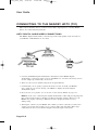
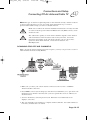
HOW TO CONNECT YOUR SATELLITE RECEIVER
Use the information in this chapter to connect your receiver to other equipment.
• CONNECTING TO THE NEARBY HDTV (TV1)
• CONNECTING TO THE REMOTE TVS (TV2)
• CONNECTING TO YOUR DISH ANTENNA
• CONNECTING THE PHONE LINE
• CONNECTING A VCR TO THE REMOTE TV
• CONNECTING OFF-AIR ANTENNA/CABLE TV
• USING TROUBLESHOOTING TOOLS
• WIRING YOUR SYSTEM TOGETHER
Page 12-1
9200_Ch12_eng
5/19/05
12:08 PM
Page 2
User Guide
CONNECTING TO THE NEARBY HDTV (TV1)
This section describes how to connect receiver TV1 output ports to a nearby HDTV.
Select one of the following methods.
HDTV DIGITAL AUDIO/VIDEO CONNECTIONS
The HDTV Digital Audio/Video connection provides high-quality audio and video to
your HDTV or HD Monitor in one cable.
1. Connect an HDTV Digital Audio/Video cable between the HDTV Digital
Audio/Video connection on the receiver and HDTV set or monitor. You may need to
use the adapter provided with your receiver.
2. Turn on your receiver and TV using the front panel buttons.
3. Confirm that you are getting a picture from the receiver. Consult your HDTV
user’s guide if you need to change your HDTV to display from the Digital
Audio/Video input.
4. If you do not see a picture, see No Picture on the Nearby HDTV on page 12-3.
Note: In most cases connecting the Digital Audio/Video cable will provide plug-andplay control of the monitor’s display resolution and other settings. However, your
HDTV may require selecting a different format to display from the receiver
during setup.
5. Turn up the volume on your HDTV and confirm you have sound. If you don’t have
sound, your system may require you to connect audio (red and white) RCA-type
cables between the receiver Audio Outputs and audio input connections.
Page 12-2
9200_Ch12_eng
5/19/05
12:08 PM
Page 3
Connections and Setup
Connecting To The Nearby HDTV (TV1)
12
YPBPR CONNECTIONS
1. Connect between the YPbPr component connections on the receiver and the nearby
HDTV using component video cables.
2. Connect audio (red and white) RCA-type cables between the receiver Audio Outputs
and audio input connections that go with the YPbPr connectors on your HDTV
or monitor.
3. If you do not see a picture, change the resolution setting on the receiver.
4. Turn up the volume on your HDTV and confirm you have sound. Check the RCAtype connections if you don’t have sound.
NO PICTURE ON THE NEARBY HDTV
This section will help you make a picture on the nearby HDTV in the event that you
could not do so in the previous sections.
1. Connect RCA-type cable connections between the receiver TV2 Out and the
Nearby HDTV.
2. Make sure the receiver and nearby HDTV are on.
3. Make sure the nearby HDTV is set to display TV2. Look on the back of your HDTV
and consult your HDTV user’s guide.
4. Make sure you have the remote control antenna attached as described on page 2-7.
5. On the receiver front panel, press SYS INFO
Page 12-3
9200_Ch12_eng
5/19/05
12:08 PM
Page 4
User Guide
6. On Remote Control 2, press RECORD.
7. Change the HDTV settings as described in the next section.
8. Switch to the nearby HDTV to display TV1. If you have a picture from TV1,
you are finished.
9. Repeat steps 6 through 8 until the nearby HDTV displays video from the receiver.
SETTING UP TO DISPLAY IN HD
Once the receiver has been activated with qualifying Bell ExpressVu programming, you
will be able to receive HD programs to watch. Use the following steps to select the
desired HDTV format.
1. Consult your HDTV user’s guide for the HD format resolution that the TV supports
(1080i or 720p).
2. Press MENU, select System Setup (6), and then HDTV Setup (8) to open the receiver
HDTV Setup screen.
3. Select the HD format settings (Analog Type and TV Type) that matches the format
your TV supports.
4. While in this menu, select the Aspect Ratio option that matches your TV:
• 16x9 is the setting for wide screen HDTV display.
• 4x3 #1 is the setting to use on a 4x3 TV which uses vertical compression. When
fed with a 16x9 program, a compatible TV automatically makes the picture
letterbox format (black bars top and bottom), to preserve the correct horizontal and
vertical proportions.
Page 12-4
9200_Ch12_eng
5/19/05
12:08 PM
Page 5
Connections and Setup
Connecting To The Remote TVs (TV2)
12
• 4x3 #2 is the setting to use on a 4x3 TV which does NOT have internal vertical
compression. When fed with a 16x9 program, such a TV will not show black bars
at the top and bottom, and the picture will appear tall and skinny.
5. Press Done.
6. If required, set up the HDTV to display in the format you desire. Some HDTVs will
automatically adjust to the resolution setting of the receiver.
CONNECTING TO THE REMOTE TVS (TV2)
This section describes how to connect the receiver CH 21–69 Out connection to the
cable ready remote TV located in another room away from the receiver. This installation
uses your in-home cable system. If your house does not have built-in cabling, it will be
necessary to run cables from the receiver to each remote TV. Due to the difficulty of this
installation, you should consider having this professionally installed. Call Bell
ExpressVu at 1-888-SKY-DISH.
CONNECTING OTHER TV(S) (TV2)
• If connecting to your in-home cabling system to distribute the signal to a TV(s) in
other rooms, in most cases you will not have to install the attenuator on the CH 21–69
port for typical in-home cabling systems.
• If connecting directly to a nearby TV tuner port, you must install the attenuator in the
cable between the CH 21–69 Out port and the TV tuner.
If you have an off-air antenna or cable connected to your in-home cable
system, see Connecting Off-Air Antenna/Cable TV following this section.
Page 12-5
9200_Ch12_eng
5/19/05
12:08 PM
Page 6
User Guide
Make sure you are familiar with how to change channels on your TV and if
necessary how to switch your TV between off-air and cable channels.
During this procedure, it will be necessary to change the channels on your
TV(s) to tune to these channels to see the video from the receiver. See your
TV user’s guide for instructions.
1. Connect the tuner input of the remote TV(s) in other rooms to an existing wall cable
outlet using a coaxial cable.
2. Turn on every remote TV connected to the in-home cabling system.
3. Find three channels next to each other on one of your remote TVs that do not pick
up any signals from off-air or cable broadcasts (they should show nothing but snow
or static).
These channels must fall in one of the two ranges below. For example, if you find that
cable channels 75, 76, and 77 do not pickup any broadcasts, pick these channels since
they fall into the range below for cable channels. Make sure these three channels on
other remote TVs also do not pick up broadcasts.
• Air Mode - Select a channel between 21 and 69 if your TV(s) will be set in
Air Mode.
• Cable Mode - Select a channel between 73 and 125 if your TV(s) will be set in
Cable Mode.
Note: The remote TV(s) will have to be set to the same channel mode, either off-air
or cable channel mode for this installation. See your TV user’s guide for instructions
on how to set your TV to off-air or cable channel modes.
4. Pick the channel in the middle of the three you selected in step 3. Write that channel
down in the blank provided in step 5. For example, if the three channels you picked in
the preceding step were air channels 60, 61, and 62, pick channel 61 and write it in
space provided in step 5.
5. If your TV is in off-air mode for the channels you picked in step 4, circle “Air” below.
If your TV is in cable mode for the channels you picked in step 4, circle “Cable”
below.
Channel: _______________
Air/Cable
6. Set all of your remote TV(s) to the channel mode (Air or Cable) you wrote in step 5.
7. Tune all of your remote TV(s) to the channel you wrote in step 5. This is the channel
you will use to receive your satellite programming.
8. Connect CH 21-69 Out on the receiver to your existing wall cable outlet using a
coaxial cable.
Note: If you do not have an existing in-home cable system, you will need to run
coaxial cable to each TV in other rooms. If this is too difficult, you may want to
contact a professional to do this installation.
Page 12-6
9200_Ch12_eng
5/19/05
12:08 PM
Page 7
Connections and Setup
Connecting To The Remote TVs (TV2)
12
9. Place the yellow sticker on the CH 21-69 Out cable near where the cable attaches to
the receiver. The stickers are located inside the front cover of this guide.
10. Turn on the nearby HDTV (the TV that gets programming from the TV1 outputs).
11. Make sure the receiver's green TV1 indicator is on.
12. Select the Modulator Setup (Menu 6-1-5).
13. With the Modulator Setup screen displayed on the nearby HDTV, use Remote Control
1 to do the following:
a Under TV2 Out, select either Air (for off-air channel numbers) or Cable (for cable
channel numbers) based on what you wrote down in step 5.
b Under TV2 Out, use the UP and DOWN ARROWS to change the modulator
channel to the one you wrote in step 5.
c Select Done.
14. For some TVs, you must run a channel scan so that the TVs will find and display the
selected channel from the receiver. Run channel scan on all remote TV(s), if available.
See your TV user’s guide for instructions.
15. Confirm that you see a picture from the receiver TV2 output on your remote TV(s).
•
If your picture looks good, go to step 23.
•
If your TV(s) do not have a picture or if it is not as clear as you would like it to
be, go to the next step.
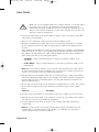
16. You may need to change the cable connection on the splitter that sends the TV signal
throughout your house. The change that needs to be made is move the cable coming
from the receiver CH 21-69 Out from the output of the splitter to the input of the
splitter using the instructions that follow.
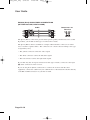
The following figure shows an example of what your splitter may look like. Your
splitter may look different. The places where the splitter indicates Out refers to all
TVs connected to your cable system. The places where the splitter indicates In refers
to where the TV signal is fed into the splitter.
Page 12-7
9200_Ch12_eng
5/19/05
12:08 PM
Page 8
User Guide
17. Find where the TV signal is distributed throughout your house. It should be near
where the cable TV service enters the house.
18. Disconnect the cable TV service cable or antenna cable from the splitter input, if
necessary. Make sure the disconnected cable is capped or otherwise protected from
the weather.
19. Disconnect the cable coming from the receiver CH 21–69 Out port from the splitter. If
you do not know which cable this is, go to the next step. Otherwise, go to step 21.
20. If you have multiple TVs on the cable system, do the following to determine which
cable on the splitter is coming from the receiver:
• If you have at least some picture on your TV(s), turn on all remote TVs connected
to the cable system. Disconnect and reconnect each cable one by one observing
what happens to the TV(s). When all remote TVs lose the signal, you have
disconnected the receiver’s cable. If only some or one TV loses the signal, then
you have disconnected a cable from the TV(s).
• If the above step does not work, disconnect one of the output cables and connect to
the splitter input. If you do not see a picture, connect the cable back to its output.
Repeat this step on every connection until you get a picture on the remote TV(s).
21. Reconnect the receiver’s cable to the input of the splitter.
22. Make sure you have a good picture on your remote TV(s).
23. If desired to remind you of which TV channel your satellite programming is on, write
the channel number you wrote in step 4 on a blank channel sticker and place it on or
near your remote TV(s). The stickers are inside the front cover of this guide.
24. Confirm Remote Control 2 controls the receiver. See page 10-3 for instructions.
25. Program Remote Control 2’s RECOVER to the channel you selected in step 5.
See page 10-17 for instructions.
Page 12-8
9200_Ch12_eng
5/19/05
12:08 PM
Page 9
Connections and Setup
Types of TV2 Connections
12
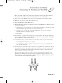
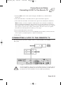
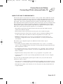
TYPES OF TV2 CONNECTIONS
RF OR VHF CONNECTIONS (GOOD PICTURE AND SOUND)
Cable
Connectors on
Receiver
The RF or VHF connections (also called the modulator connections) provide good
picture and good mono ("non-stereo") sound quality. Be aware that even if you have a
TV and other equipment that support stereo sound, this type of connection will give you
only non-stereo sound.
Using the RF or VHF connections allows you to quickly switch from satellite
programming to local or cable programming using one of the following methods:
• Press the TV/Video button on the remote, or
• Turn OFF the receiver
Page 12-9
9200_Ch12_eng
5/19/05
12:08 PM
Page 10
User Guide
PHONO (RCA) AUDIO/VIDEO CONNECTIONS
(BETTER PICTURE, BEST SOUND)
Cable
Connectors on
Receiver
VIDEO
1
VIDEO
R
R
AUDIO 1 AUDIO 2
The phono (RCA) connections provide better picture quality and the best stereo sound.
If possible, you should use this type of connection for audio.
The phono (RCA) cable is available as a single cable with three connectors on either
end, or as three separate cables. The connectors are colour-coded according to the type
of signal they carry.
• The yellow connector carries the video signal.
• The white connector carries the left audio signal.
• The red connector carries the right audio signal.
If your TV only has one input connection for this type of audio, connect it to the right
(R) audio connection on the receiver.
If you use the phono (RCA) connections to connect the receiver with the other
equipment, connect the cable from your cable TV box or broadcast TV antenna directly
to the RF or VHF connection on your TV or VCR.
Page 12-10
9200_Ch12_eng
5/19/05
12:08 PM
Page 11
Connections and Setup
Connecting To Your Dish Antenna
12
CONNECTING TO YOUR DISH ANTENNA
1. Before you can begin connecting your receiver to your dish antenna, you must first
complete the preceding sections on connecting your TVs to the receiver.
2. Connect two RG-6 coaxial cables between the Satellite In 1 and Satellite In 2 ports on
the receiver’s back panel to two available ports on either your switch or your LNBF in
your existing system.
3. Peel off the blue stickers and affix them to the cables close to where they connect to
the Satellite In 1 and Satellite In 2 connections on the back of the receiver. The
stickers are in the front cover of this guide.
4. On Remote Control 1, press Menu, select System Setup (6), Installation (1), and then
Point Dish (1) to display the Point Dish screen on the nearby HDTV.
5. Select Check Switch. Select Test.
6. The receiver begins performing the Check Switch tests. When it is finished, the
Installation Summary screen displays.
7. Make sure that the information on the Installation Summary screen identifies your
system correctly and shows all transponders for all satellites in your system.
8. Select Done to go to the Point Dish/Signal screen.
9. Select Cancel to exit the Point Dish menu. At this point, the receiver may walk you
through a procedure to download software. If this prompt displays, follow the
instructions and do not disturb the receiver until the nearby HDTV is displaying Bell
ExpressVu video. Otherwise, press View TV. After a few minutes, you should be
watching TV.
Page 12-11
9200_Ch12_eng
5/19/05
12:08 PM
Page 12
User Guide
CONNECTING THE PHONE LINE
You must keep the receiver connected to an active telephone line to order Pay-Per-View
programs, use all of the Interactive features, or other services from Bell ExpressVu with
your remote control.
Note: You may be able to use a wireless modem jack. However, this may not support all
the features of this receiver, such as Caller ID.
Note: If you have a Digital Subscriber Line (DSL), you may have to install a DSL filter
between the receiver’s back panel Phone Jack and the telephone wall jack to successfully
connect with Bell ExpressVu. You can obtain a filter from your DSL provider.
PHONE LINE CONNECTION
Run a telephone cable with a standard RJ-11 connector from the receiver’s back panel
Phone Jack to an active telephone connection.
PHONE SYSTEM SETUP
You must also set up the receiver for your telephone system (touch tone or rotary), and
set a telephone number prefix, if you need a prefix to make an outside call.
Page 12-12
9200_Ch12_eng
5/19/05
12:08 PM
Page 13
Connections and Setup
Connecting A VCR To The Remote TV
12
1. Pressing MENU, then select System Setup (6), Installation (1), and then Phone
System (4).
2. Select the Touch Tone or the Rotary Phone option in the Phone Type list.
3. Select either the No Prefix or the Prefix Code option in the Outside Line Prefix list.
Note: Usually, you need a telephone number prefix only for business installations.
For most residential installations, all you need to do is set the telephone system type.
The default setting of No Prefix will allow correct dialing. If this is the case, select the
Done option to save the above setting, and stop here. If you do need to set a prefix,
then instead of selecting the Done option, go on to step 5.
4. If you selected No Prefix, select Done.
5. If you selected Prefix Code, the receiver highlights the box where you must enter the
exact sequence you dial the phone to obtain an outside line.
6. Select Done.
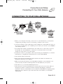
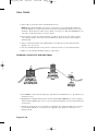
CONNECTING A VCR TO THE REMOTE TV
The diagram below provides example of how to connect VCRs to your satellite
TV system.
For this installation, always leave your VCR powered on so that the TV can
receive satellite programming. If you turn off your VCR, your TV will not
be tuned to the correct channel to receive satellite programming.
Page 12-13
9200_Ch12_eng
5/19/05
12:08 PM
Page 14
User Guide
1. Connect the tuner input of the remote VCR to an existing wall cable outlet using a
coaxial cable.
2. Connect a coaxial cable from the output on the VCR to the remote TV’s tuner port.
3. Plug in and turn on the remote VCR and TV.
4. Tune the remote VCR to the remote TV channel that you use to watch satellite TV
programming (for example, channel 60) as set on page 12-6.
5. Write the channel number you tuned your VCR to in the previous step on one of the
TV2 channel stickers. Place the sticker on or near the VCR. This sticker will remind
you which VCR channel to use to watch satellite programming. The stickers are
located in the inside front cover of this guide.
6. Set the VCR output to channel 3 or 4.
7. Tune the remote TV to the same channel that you set your VCR to in step 6.
8. Write the channel number you tuned your TV to in the previous step on one of the
TV2 channel stickers. Place the sticker on or near the TV. This sticker will remind you
which channel to use to watch satellite programming. The stickers are located in the
inside front cover of this guide.
CONNECTING OFF-AIR ANTENNA/CABLE TV
If you want to receive channels from an off-air antenna or cable in addition to your
satellite receiver programming, connect the off-air antenna/cable into your TV
distribution equipment.
• The 8VSB TV Antenna/Cable In on your receiver's back panel can be used to receive
and view programming on the nearby HDTV from an off-air antenna or cable service.
• Connect a VHF/UHF off-air antenna or analog cable TV source to the 8VSB TV
Antenna/Cable port. Peel off the black sticker and affix it to the cable close to where
it connects to the back of the receiver. The stickers are inside the front cover of
this guide.
• Not all off-air broadcasts can be recorded with your receiver.
• The remote TV can view to off-air channels only in Single Mode.
• For remote TVs receiving programming from CH 21-69 Out, the off-air antenna needs
to be connected to your TV distribution equipment. TV distribution equipment devices
include coax panels, amplifiers or super home nodes, and are available through
many companies.
• You can add local off-air channels and assign them network affiliations. Once you
have done this, you can access the channels via the Program Guide or the Browse
Banner in much the same way as you would satellite channels.
Page 12-14
9200_Ch12_eng
5/19/05
12:09 PM
Page 15
Connections and Setup
Connecting Off-Air Antenna/Cable TV
12
Note: The type of antenna required depends on the channels used by, and the locations
of, the local broadcasters for your area. Visit www.antennaweb.org or contact a
professional installer to help you select a suitable antenna.
Make sure to follow the antenna installation instructions correctly. Ground
an outdoor antenna per the National Electrical Code (NEC) and any local
electrical codes.
The audio/video quality on local off-air channels depends on the distance
and terrain between the broadcast station and your home, and on the
placement and quality of the off-air TV antenna you use. If you have
questions about offair channels, contact the broadcaster, not
Bell ExpressVu.
SCANNING FOR OFF-AIR CHANNELS
With your off-air antenna adjusted for best reception, you may now proceed to scan for
offair channels from the nearby HDTV.
1. Make sure you have your off-air antenna connected to the receiver’s 8VSB TV
Antenna/ Cable connection.
2. Press MENU, select System Setup (6), and then Local Channels (9) to open the Local
Channels screen. If this is the first time you have opened this screen, it will have no
channels listed.
3. Scan for channels by selecting Scan Locals. When the Local Channels screen
displays, select Yes.
4. The scan will take a few minutes to complete. When it finishes, the results will show
how many channels the scan found.
Page 12-15
9200_Ch12_eng
5/19/05
12:09 PM
Page 16
User Guide
5. Select OK to go back to the Local Channels screen.
Note: If the channel number says None, you have not yet assigned this channel a
network affiliation or name. The Arrow at the bottom left means that there are more
channels, off the bottom of the screen, which you can get to with the ARROW keys if
you wish to edit their names or remove them.
6. If you want to name the off-air channels, continue on. If you do not want to name
your offair channels, select Done. You will then be taken out of the menus back to
watching TV.
7. Select a channel and then select Edit Name to modify the way the channel name
displays on your screen.
8. Use the virtual keyboard on the screen to select the letters of your channel name.
9. When you are finished making changes, select Done.
PEAKING YOUR OFF-AIR ANTENNA
1. Press MENU, select System Setup (6), and then Local Channels (9) to open the Local
Channels screen.
2. Highlight the Channel field and use the UP and DOWN ARROWS to select a digital
off-air channel. Make sure you see a green signal strength bar and a Locked indication
on the meter.
3. Adjust the orientation of your antenna to maximize the signal strength. If you cannot
get a Locked indication, you may need to upgrade your antenna or relocate it to a
better position.
Page 12-16
9200_Ch12_eng
5/19/05
12:09 PM
Page 17
Connections and Setup
Connecting Off-Air Antenna/Cable TV
12
ABOUT OFF-AIR TV BROADCASTS
Off-air TV signals are broadcast from stations on the ground, while satellite TV signals
are broadcast from satellites in space. You receive off-air TV signals using an indoor or
outdoor antenna instead of the satellite dish. You are likely familiar with analog off-air
TV signals - these are the signals that have been used to broadcast TV for many years.
New digital off-air TV signals are broadcast and received in the same way. Digital off-air
TV broadcasting uses advanced technology like that of the Bell ExpressVu to deliver
superb picture quality and CD quality sound. However, digital off-air signal reception
(like analog off-air signal reception) depends on several things:
• The distance between the broadcast station and your home (the farther away the
station, the weaker the signal);
• The broadcast station's power (the lower the power, the weaker the signal);
• Obstacles between the station and your home, such as mountains, buildings, trees,
or other objects (these may block or reflect the signal before it reaches you);
• Multiple broadcast stations (to receive good signals from several stations, you
may need to compromise in how you aim the antenna or you may need more than
one antenna).
The effects of poor digital reception are different from the effects of poor
analog reception:
• Poor analog reception usually causes the TV picture to be “snowy” or to include
“ghosts,” that is, multiple images caused by receiving reflected signals along with the
direct signal from a station.
• Poor digital reception may cause the TV picture to be “pixelized,” that is, broken up
into small squares of various colours, or to be lost completely (the TV screen is all
black or all blue).
• Digital broadcasts often provide either a very good picture or no picture at all.
• You may be able to receive a poor analog signal but not be able to receive a digital
signal at all.
To get the best possible digital signal reception, make sure you use the best off-air
antenna for where you live:
• You can receive a limited number of channels using a rabbit ears type antenna on top
of the TV set, or a much larger number via a large UHF/VHF indoor/outdoor antenna.
• The higher the quality of the antenna you use, the greater its range and the better its
reception will be.
Page 12-17
9200_Ch12_eng
5/19/05
12:09 PM
Page 18
User Guide
The Consumer Electronics Association maintains a website, www.antennaweb.org, that
you can visit for help in choosing an antenna.You may want to contact a professional TV
antenna installer for advice or help in choosing, installing, and aiming an antenna. Keep
in mind, digital off-air TV broadcasting is in its infancy. So, digital off-air service may
be interrupted because:
• Broadcasters are testing digital signals, and may stop broadcasting without notice.
• Many broadcasters do not yet have permanent broadcast stations and may be
operating at less than full power.
• Broadcasters are not legally required to provide full-time digital signals for
several years.
• Some digital channels do not broadcast all the time.
If you have questions about off-air channels, contact the broadcasters, not Bell
ExpressVu. Bell ExpressVu does not broadcast off-air signals and so cannot do anything
to change offair signal quality. However, the receiver's digital channel setup menus
provide a signal strength bar that can help you in aiming the off-air TV antenna for the
strongest possible signal.
USING TROUBLESHOOTING TOOLS
Your receiver has diagnostics tools that a Customer Service Representative may ask you
to use if you should ever run into problems while using your equipment. Even though
these tools are quite helpful, it is recommended that you only use them when on the
phone with a Bell ExpressVu representative.
RESETTING YOUR RECEIVER
Reset your receiver as directed by the Customer Service Representative as follows:
1. Press and hold the front panel POWER until only the green TV1 indicator is lit.
2. Let go of the front panel POWER.
It will take a few minutes for your receiver to reset and come back on. When you reset
your receiver, your receiver may have to download an updated Program Guide. If this
is the case, it may take longer for the receiver to come back on.
Page 12-18
9200_Ch12_eng
5/19/05
12:09 PM
Page 19
Connections and Setup
Using Troubleshooting Tools
12
DIAGNOSTICS
The Customer Service Representative may ask you to open the Diagnostics screen.
Remember to have an active phone line connected to your receiver.
1. Press MENU, select System Setup (6), and then select Diagnostics. The Diagnostics
screen shows you various tests the Customer Service Representative may ask you to
perform on your receiver:
• Connection - Tests for a valid receiver phone connection.
• Dial Out - If “No Dial Out Pending” is displayed, the receiver does not need to
have its smart card records updated.
• Counters - Shows you a list of diagnostic counters. Use PAGE UP and PAGE
DOWN to scroll through the list of counters displayed.
2. Select Done.
POINT DISH AND CHECK SWITCH
The Point Dish and Check Switch screens are helpful to the Customer Service
Representatives. You may be asked to display these screens when you call Bell
ExpressVu. Even though there are items that can be changed, only change them when
specifically directed by a Customer Service Representative.
1. Press MENU.
2. Select System Setup.
3. Select Installation.
Page 12-19
9200_Ch12_eng
5/19/05
12:09 PM
Page 20
User Guide
4. Select Point Dish. This screen shows you information to help maximize your satellite
signal. The bar at the bottom of the screen tells you the signal strength. Green is a
good signal, while red indicates the signal is not acceptable or is from the
wrong satellite.
5. Select Check Switch to display the Installation Summary screen. The Installation
Summary screen tells you if you are receiver signals from the satellites and which
multidish switches you have installed, if any.
6. Select Test only if directed by the Customer Service Representative.
7. Select Done.
Page 12-20
9200_Ch12_eng
5/19/05
12:09 PM
Page 21
Connections and Setup
Wire Your System Together
12
WIRING YOUR SYSTEM TOGETHER
MULTIPLE RECEIVERS
Each output on the LNBF can support a single receiver. You cannot connect two
receivers to the same output (for example, by using a line splitter), because the two
receivers would interfere with each other during channel selection. This is a
characteristic of satellite television in general, and is not a limitation that is specific to
this Bell ExpressVu system.
If you want to connect two receivers to the same Bell ExpressVu satellite antenna and be
able to watch different channels on each, you must use a dual-output LNBF. This allows
you to connect each receiver to a different output, preventing interference between the
receivers. In this case, during installation you must run a separate coaxial cable from
each output on the LNBF to each receiver.
If you want to purchase an LNBF different from the one that you originally purchased,
contact your local Bell ExpressVu Authorized Agent.
The following wiring setups assume installation of a single receiver. If you are installing
multiple receivers, modify your wiring accordingly.
ABOUT CABLING AND CONNECTIONS
The way in which you wire your system and the kinds of cabling you choose can make a
noticeable difference in the quality of the picture and sound. We recommend that you
wire your system to take advantage of the highest quality supported by your equipment.
You will need to examine your electronic equipment to determine what type of
connectors and cables, and which wiring setup to use.
Do the following:
1. Look on the back of each piece of equipment that you are planning to install with the
Bell ExpressVu receiver and note the type of connectors on the equipment.
2. Starting from the connectors that support the highest quality, determine which pieces
of equipment can be connected together using the designated type of cable.
3. Review the wiring setups starting from page 12-1 to determine which one is the
closest to your planned configuration.
4. Use that setup as the basic plan to wire your system together. If you have additional
components, or do not have all of the components that are in the setup, adjust the
wiring accordingly.
Page 12-21
9200_Ch12_eng
5/19/05
12:09 PM
Page 22
User Guide
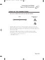
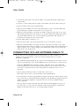
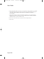
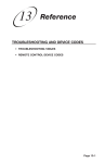
WIRING SETUP DIAGRAMS
These Installation Instructions provide only the basic wiring setup diagram below.
Note: The off-air television antenna shown in the following diagram is optional.
HDMI
DVI (D)
DVI (D)
Adapter
TV2
TV1
HDMI
D UA L -O U T P U T
Page 12-22