1
INSTRUCTION MANUAL
GPS16X-HVS GPS Receiver
March 2014
Copyright © 2008 - 2014
Campbell Scientific Inc.
Table of Contents
PDF viewers: These page numbers refer to the printed version of this document. Use the
PDF reader bookmarks tab for links to specific sections.
1. Overview ...................................................................... 3
2. Wiring .......................................................................... 3
3. GPS Data ..................................................................... 7
4. CRBasic Programming ............................................... 8
4.1 Read GPS Data ......................................................................................... 8
4.1.1 SerialOpen....................................................................................... 8
4.1.2 SerialIn ............................................................................................ 8
4.1.3 SerialFlush ...................................................................................... 9
4.2 Parsing and Data Storage Options ............................................................ 9
4.2.1 SplitStr ............................................................................................ 9
4.2.2 Converting Strings to Floating Point Numbers ............................... 9
5. Troubleshooting........................................................ 11
5.1 GPS Setup and Function ......................................................................... 11
Appendices
A.1 Programming .......................................................... 12
A.1.1
A.1.2
A.1.3
A.1.4
A.1.5
A.1.6
Program Execution Interval ................................................................ 12
Reading GPS Data .............................................................................. 12
Filters .................................................................................................. 13
Managing the Data .............................................................................. 14
Program Discussion ............................................................................ 15
Troubleshooting .................................................................................. 19
B.1 Replacement Parts ................................................. 20
B.2 Specifications ......................................................... 20
1
GPS16X-HVS GPS Receiver
Figures
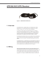
Figure 0—1 GPS16X-HVS GPS Receiver ........................................................................................................... 3
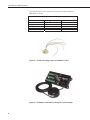
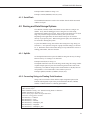
Figure 2—1 RJ45 with Flying Leads, Part Number L17217 .............................................................................. 4
Figure 2—2 CR1000 to GPS16X-HVS Using the L17218 Adapter .................................................................. 4
Figure 2—3 RJ45 to DB9 Serial Adapter, Part Number L17218 ....................................................................... 5
Figure 2—4 GPS16X-HVS Receiver Mounting Kit, Part Number C1737 ........................................................ 6
2
GPS16X-HVS GPS Receiver
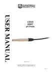
GPS16X-HVS GPS Receiver
Figure 0—1 GPS16X-HVS GPS Receiver
1. Overview
The GPS16X-HVS is a complete GPS receiver manufactured by Garmin
International, Inc. The GPS16X-HVS has been configured by Campbell
Scientific (Canada) Corp. (CSI) to work with CSI dataloggers.
The CR1000, CR3000, CR800, and CR850 dataloggers use serial input
instructions and string handling functions to read, parse and store GPS data.
The CR23X, and other dataloggers that support P15 or the SDM-SIO4 four
channel serial interface can be used with the GPS16X-HVS. Note that the
GPS16X-HVS is not compatible with the CR510, CR10X, or CR200.
The GPS16X-HVS includes the GPS receiver and antenna in the same housing
with one cable for the power supply and communications. The GPS antenna
must have a clear view of the sky. Generally the GPS antenna will not work
indoors.
The GPS16X-HVS is a 12-channel GPS receiver that supports FAA Wide Area
Augmentation System (WAAS) or RTCM differential GPS. Also supported is
the 1 Pulse Per Second (PPS) timing signal. The cable connections provided
with the GPS16X-HVS do not support differential GPS correction. The cable
can be modified by the user if differential correction is required.
2. Wiring
Wiring for the GPS16X-HVS can be done with or without the RJ45 connector.
When shipped from Campbell Scientific, the GPS16X-HVS has an RJ45
connector attached to the cable end. The GPS16X-HVS can be purchased with
an RJ45 adapter with flying leads, an RJ45 to DB9 RS-232 adapter, and the
C1737 mount. Table 2-1 is the wiring description for the RJ45 adapter with
flying leads. To use Table 2-2, the RJ45 connector must be cut off the cable.
3
GPS16X-HVS GPS Receiver
If the GPS16X-HVS is to be connected to a computer for setups, an RJ45 to
DB9 adapter is needed.
TABLE 2-1. Wiring the RJ45 Connector with Flying Leads
GPS16X-HVS
Blue
Orange
Black
Green
Yellow
Datalogger Connection
12 volts
Ground
Ground
Data in
None
Function
Power
Power Ground
Remote on/off
RS232 TX out of GPS
1 Pulse Per Second
Figure 2—1 RJ45 with Flying Leads, Part Number L17217
Figure 2—2 CR1000 to GPS16X-HVS Using the L17218 Adapter
4
GPS16X-HVS GPS Receiver
TABLE 2-2. Wiring without the RJ45 Connector
(Garmin Wiring)
GPS16X-HVS
Pin
Color
1
Red
2
Black
3
Yellow
4
5
6
7
8
Blue
White
Gray
Green
Violet
Function
Power in, 6.0 to 40 volts DC
Power ground
Remote power on/off switch, ground for on, float
for off
Port 1 Data in, RS232 or TTL levels OK
Port 1 Data out, RS232 Levels
PPS
Port 2 Data in, RS232 or TTL levels, DGPS input
Port 2, Data out, RS232, reserved for future use
TABLE 2-3. RJ45 to DB9 RS-232 Adapter
Pin
NA
NA
NA
5
3
2
Color
Red
Black
Yellow
NA
NA
NA
Function
Power in, 12 volts
Ground
PPS
GPS, power and remote on/off ground
GPS data in
GPS data out
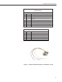
Figure 2—3 RJ45 to DB9 Serial Adapter, Part Number L17218
5
GPS16X-HVS GPS Receiver
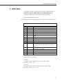
Figure 2—4 GPS16X-HVS Receiver Mounting Kit, Part Number
C1737
6
GPS16X-HVS GPS Receiver
3. GPS Data
The GPS16X-HVS has several data formats available. The GPS16X-HVS is
configured to output the NMEA $GPGGA time and position string. It is
possible to configure the GPS16X-HVS to output other NMEA strings
including the $GPVTG track made good and ground speed string.
Sample NMEA $GPGGA data string:
$GPGGA,hhmmss,llll.lll,a,nnnnn.nnn,b,t,uu,v.v,w.w,M,x.x,M,y.y,zzzz*hh<CR><LF>
TABLE 3-1. NMEA $GPGGA String Definition
Field
0
1
2
3
4
5
6
Description
$GPGGA
hhmmss
1111.111
a
nnnnn.nnn
b
t
7
8
9
10
11
12
uu
v.v
w.w
M
x.x
M
13
y.y
14
15
16
17
zzzz
*
hh
<CR><LF>
NMEA string identifier
UTC of Position: Hours, minutes, seconds
Latitude: Degrees, minutes, thousandths of minutes
N (North) or S (South)
Longitude: Degrees, minutes, thousandths of minutes
E (East) or W (West)
GPS Quality Indicator: 0 = No GPS, 1 = GPS, 2 =
DGPS
Number of Satellites in Use
Horizontal Dilution of Precision (HDOP)
Antenna Altitude in Meters
M = Meters
Geoidal Separation in Meters
M = Meters. Geoidal separation is the difference
between the WGS-84 earth ellipsoid and mean-sealevel.
Age of Differential GPS Data. Time in seconds since
the last Type 1 or 9 Update
Differential Reference Station ID (0000 to 1023)
Asterisk, generally used as the termination character
Checksum
Carriage return, line feed characters.
Sample $GPGGA output strings:
Cold Start
No satellites acquired, Real Time Clock and Almanac invalid:
$GPGGA,,,,,,0,00,,,,,,,*66
Warm Start
No satellites acquired, time from Real Time Clock, almanac valid:
$GPGGA,235032.0,,,,,0,00,,,,,,,*7D
7
GPS16X-HVS GPS Receiver
Warm Start
One satellite in use, time from GPS Real Time Clock (not GPS), no position:
$GPGGA,183806.0,,,,,0,01,,,,,,,*7D
Valid GPS Fix
Three satellites acquired, time and position valid:
$GPGGA,005322.0,4147.603,N,11150.978,W,1,03,11.9,00016,M,016,M,,*6E
If the almanac and ephemeris data are not stored in the non-volatile data, GPS
acquisition time is less than 5 minutes. If only the ephemeris data are unknown,
acquisition time is less than 45 seconds. If all data are known (warm start),
GPS acquisition time is less than 15 seconds.
4. CRBasic Programming
CRBasic is used to write programs for the CR1000, CR3000, CR800, and
CR850 dataloggers. These dataloggers use several instructions to read GPS
output, which is asynchronous serial data. As shipped from Campbell
Scientific, the GPS receiver will output data once a second, 4800 baud, 8 data
bits, no parity, and 1 stop bit. Only the GPGGA string is output. See Section 3
for details on the GPGGA string. See Appendix C for specifics on changing
the GPS receiver setups, including using higher baud rates, which the CR1000,
CR3000, CR800, and CR850 support.
In the following program example please note that both output tables may not
be required, and are only examples. The output intervals of the data tables are
also of concern. These items must be considered when determining the output
data required for individual applications and any potential data storage
constraints. Finally, the use of the PPS line is not addressed for the CR1000,
CR3000, CR800, and CR850 dataloggers. Typically this is not required due to
these dataloggers’ ability to execute tasks concurrently.
4.1 Read GPS Data
4.1.1 SerialOpen
SerialOpen is used to open the appropriate serial port, specify the baud rate,
data format, etc. Any of the six serial ports may be used, but option codes 3
and 4 are not used in this application. Data format is zero, TX delay is zero,
buffer size should be about 2000, which is large enough to prevent the GPGGA
string from overrunning the buffer before data is read by the SerialIn
instruction. If memory is limited, the buffer size can be smaller.
Example: SerialOpen (com1,4800,0,0,2000)
4.1.2 SerialIn
The SerialIn instruction removes data from the buffer declared in the
SerialOpen instruction and places the data in a variable of type string. Use a
timeout of 20, a termination character of 13, and maximum number of
characters of 100, or 1 less than the size of the destination variable. Declare a
string variable of size 101 before using SerialIn.
8
GPS16X-HVS GPS Receiver
Example: Public GPSdata as string * 101
Example: SerialIn (GPSData,com1,20,13,100)
4.1.3 SerialFlush
The SerialFlush instruction is used to clear all data from the buffer associated
with the serial port.
4.2 Parsing and Data Storage Options
The CR1000, CR3000, CR800, and CR850 can store data as a string or as a
number. Every time the datalogger stores a string, the size of the string
determines the number of bytes used. If the string was declared to be 101 bytes
long, every time the string is written to memory, 101 bytes are used.
Depending on the application, the entire GPGGA string can be stored to
memory or just specific parts. When storing specific parts, some numbers can
be converted to floating data points.
To parse the GPGGA string, first read the entire string into 1 large string (see
Section 4.1). Next parse the string into a group of smaller strings (see Section
4.2.1). Determine which of the smaller strings to keep and which to convert to
floating point number, then store the data.
4.2.1 SplitStr
Use the SplitStr instruction to parse the GPGGA string into an array of strings.
Declare an array of 18 strings of 15 characters.
Example: ParseStr(18) as string * 15
The SplitStr instruction uses the result string, search string, filter string, number
of splits and split option to parse the search string and store the results in the
result string. The GPGGA string uses the comma character (chr(44)) between
each parameter. The comma makes a nice marker to parse on.
Example: SplitStr (ParseStr(1),GPSData ,chr(44),18,5)
4.2.2 Converting Strings to Floating Point Numbers
Strings can be converted to floats with the simple assignment operator, but
Latitude and Longitude require more precision than the CR1000, CR3000,
CR800, or CR850 will store as a floating point number.
' Sample CR1000 program to read GPS NMEA GPGGA string
Public location, bytes
public GPSData as string * 101 ' $GPGGA string about 57 characters
PUBLIC ParseStr(18) as string * 15
' Aliases allow proper labels in output data tables,
' and when viewing public variables
alias ParseStr(1) = GPGGA
Alias ParseStr(2) = Time
Alias ParseStr(3) = Latitude
Alias ParseStr(4) = Hemisphere_NS
Alias ParseStr(5) = Longitude
Alias ParseStr(6) = Hemisphere_WE
9
GPS16X-HVS GPS Receiver
Alias ParseStr(7) = GPS_Quality
Alias ParseStr(8) = Num_Satellites
Alias ParseStr(9) = HDOP
Alias ParseStr(10) = Altitude
Alias ParseStr(11) = Altitude_units
Alias ParseStr(12) = Geoidal_Sep
Alias ParseStr(13) = Geoidal_units
Alias ParseStr(14) = DGPS_Age
Alias ParseStr(15) = Diff_Ref_ID
Alias ParseStr(16) = Asterisk
Alias ParseStr(17) = Check_Sum
Alias ParseStr(18) = CRLF
' Store the ParseStrd elements of the $GPGGA string as
' short strings.
DataTable(Parsed,1,-1)
DataInterval (0,5,sec,10)
Sample(1,GPGGA,String)
Sample(1,Time,String)
Sample(1,Latitude,String)
Sample(1,Hemisphere_NS,String)
Sample(1,Longitude,String)
Sample(1,Hemisphere_WE,String)
Sample(1,GPS_Quality,String)
Sample(1,Num_Satellites,String)
Sample(1,HDOP,String)
Sample(1,Altitude,String)
Sample(1,Altitude_units,String)
Sample(1,Geoidal_Sep,String)
Sample(1,Geoidal_units,String)
Sample(1,DGPS_Age,String)
Sample(1,Diff_Ref_ID,String)
Sample(1,Asterisk,String)
Sample(1,Check_Sum,String)
Sample(1,CRLF,String)
EndTable
' Store GPS $GPGGA string as a complete string
DataTable (GGA,1,-1)
DataInterval (0,5,Sec,10)
Sample (1, GPSData, String)
EndTable
'Main Program
BeginProg
SerialOpen (com1,4800,0,0,2000)
Scan (5,Sec,0,0)
bytes = SerialInChk (com1)
SerialIn (GPSData,com1,20,13,100)
SplitStr (ParseStr(1),GPSData,CHR(44),18,5)
SerialFlush (com1)
CallTable GGA
CallTable Parsed
NextScan
SerialClose (com1)
10
GPS16X-HVS GPS Receiver
EndProg
5. Troubleshooting
Testing and evaluation of serial communications is best done by reducing the
whole system to small manageable systems. Usually some portions of the
whole system are working. The first steps involve finding what is working.
During this process you may find parts of the system that are not working or
mistakes that can be easily corrected. Fix each subsystem before testing others.
5.1 GPS Setup and Function
Test the GPS16X-HVS for proper operation including the baud rate and output
string. Use a computer, terminal emulator software, a serial port (RS232), and
a 9-pin to 9-pin serial cable. The computer and serial port can be the same as
used to communicate with the datalogger. Terminal emulation software is
pretty common. Hyperterm is supplied as part of Windows ™ and works.
Procomm ™ is another communication software package that works well.
Set up the software for the correct serial port, 4800 baud, 8 data bits, 1 stop bit
and no parity. Flow control should be off. Using the serial cable, connect the
GPS16X-HVS to the computer serial port. Power up the GPS16X-HVS. The
GPS antenna should have a clear view of the sky. Don’t expect the GPS
antenna to work indoors. The $GPGGA string should be displayed once a
second. Make sure the $GPGGA string is showing a valid GPS fix. A valid
GPS fix will display time, position and have a GPS quality number greater than
zero. Part number L17218, RJ45 to DB9 adapter, is needed to connect the
GPS16X-HVS to the computer serial cable.
11
GPS16X-HVS GPS Receiver
Appendix A. CR23X Programs
A.1 Programming
Program instruction 15 (P15) is used to read the NMEA $GPGGA string of
time and position data. Each iteration of P15 can either read the numeric fields
or read everything. When reading the numeric fields, such as time, latitude,
longitude and elevation, P15 requires non-numeric delimiters between data
points. The only available format of GPS data with delimiters is the NMEA
0183 format. Program instruction 15 (P15) reads serial data and discards nonnumeric values. All non-numeric values act as delimiters between numbers,
and decimal points can also act as delimiters. P15 can be used to import
everything in the string, character by character, and convert it to the decimal
equivalent. The decimal equivalent method is seldom used, and only when the
general area (hemisphere) is not known.
A.1.1 Program Execution Interval
Due to the sequential program instruction execution of the CR23X the Port
Interrupt Subroutine 98 is useful in synchronizing the GPS16X-HVS
measurement via the Pulse Per Second output. When the PPS signal is used to
trigger the read data function (P15), the program table execution interval does
not matter. Otherwise the timing between the GPS16X-HVS output and the
datalogger read must be considered. Generally the execution interval can not
be less than 2 seconds when the PPS signal is not used. This is discussed
further in Section A.1.5.
A.1.2 Reading GPS Data
Table A-1 is a sample CR23X P15 instruction for reading NMEA $GPGGA
data string. The second parameter has two dashes indicating data buffering has
been turned off.
TABLE A-1. P15 for NMEA $GPGGA Data String
12
Parameter
1
2
Data
1
63 --
3
4
1
05
5
1
Description
Repetitions
Configuration code for RS232 ASCII data at 4800 baud
with data buffering turned off. The -- indicates data
buffering turned off. Decimal delimiter
Delay before sending data out
Control ports. Two digit format AB. A is for
handshaking and set to zero. B in this example is control
port 5 (datalogger RCV). GPS16X-HVS communication
cable: GPS transmit to control port 5 in this example
Input location where first character to transmit is stored.
GPS16X-HVS GPS Receiver
6
7
0
42
8
9
10
11
12
100
80
1
1
0
Note: nothing is actually transmitted
Number of consecutive input locations to send
Termination character, 42 is ASCII equivalent of the
asterisk
Maximum number of characters to receive.
Delay in mS. How long to wait for $GPGGA string
Starting input location for time and position data
Multiplier, always 1.
Offset, always 0.
P15 parameters 4, 5, and 10 are somewhat variable. When using a CR23X,
parameter 4 can be set to 05, 06 or 07 depending on what control ports are
used. Wiring of the communication cable depends on the selection for
parameter 4. With a CR23X the GPS transmit wire is connected to the control
port selected in parameter 4.
P15 is executed when the PPS signal drives control port 8 high. P15 will wait
until one of three conditions is met: the time-out listed in parameter 9 has
expired, the maximum number of characters in parameter 8 have been read, or
the termination character listed in parameter 7 has been read.
P15 parameter 10 is the first input location you wish to store GPS data in.
Fifteen sequential input locations will be used to store time and position.
Example A-1. Program Instruction 15 (P15) for CR23X
Port Serial I/O (P15)
1: 1
Reps
2: 62
-- ASCII/RS-232, 4800 Baud, decimal delimiter
3: 1
Delay (units = 0.01 sec)
4: 5
Control Ports
5: 1
Output Loc [ Bulk
]
6: 0
No. of Locs to Send
7: 42
Termination Character
8: 100
Maximum Characters
9: 80
Time Out Delay (units = 0.01 sec)
10: 1
Loc [ Raw_time1 ]
11: 1
Mult
12: 0
Offset
NOTE
Communication cable wiring for:
CR23X/Example A-1 — PPS to C8, GPS transmit to C5.
A.1.3 Filters
Filters can be used to make sure P15 reads the correct data string. Filters also
ensure P15 starts to read the string at the beginning of the string. To use a
filter, follow P15 with instruction P63 (extended parameters). P63 is used to
define the filter. Enter the desired filter in P63.
13
GPS16X-HVS GPS Receiver
TABLE A-2. Filter
ASCII Equivalent
36
71
80
71
71
65
Character
$
G
P
G
G
A
A.1.4 Managing the Data
Several of the data values in the $GPGGA string are too large to view or write
to final storage. Some simple math is used to parse the data.
The UTC time is in the format hhmmss where hh is the hours, mm is the
minutes and ss is the seconds. Six digits are too many to view with the
datalogger display and some software. Add 0.3 to the raw time field. Multiply
the raw time input location by 0.01 to reduce the magnitude and place the
seconds in the fractional portion of the number. Next use P45 to write the
integer portion (hours/minutes) to a new input location, then use P44 to write
the fractional portion to another input location (seconds) and multiply that
location by 100. The last step is to use P45 again to take the integer portion of
the input location for seconds. The result is hour/minutes in one input location
and seconds in another.
The latitude and longitude can be parsed with the P15 instruction when decimal
delimiter is on. If P15, parameter 2 is 6x, where the x selects the baud rate,
every non-numeric value and decimal point will act as a delimiter. The
Degrees and Minutes will be placed in one input location, and the minute
fractional portion will be placed in the next input location. The decimal
delimiter preserves the resolution of the original measurement.
Further parsing of the latitude and longitude may be necessary. Longitude
degrees and minutes can range in value up to 18059, which exceeds the low
resolution format of the dataloggers final storage area. Either parse the latitude
and longitude degrees and minutes the same way the time was parsed, or store
the data in high-resolution format.
The GPS quality number can be used to determine if you have a valid GPS fix
and if the datalogger received the data properly. Use P89 to test if the GPS
quality number is greater than or equal to one. There is a catch to using the
GPS quality number to verify your data. P15 will write to fifteen input
locations if everything works correctly. If P15 fails to read the GPS data, only
the first input location is written to. The GPS quality number will be
unchanged. If P15 fails to read the GPS data, the value displayed in the first
input location will be 99999. The datalogger actually stores FFFFFFFFh, a
very large number. The time field includes six digits, which can be greater than
99999. This limits the usefulness of the time field as a test for a valid GPS fix.
A better approach is to overwrite the GPS quality location with zero before
executing P15. Use P30 to overwrite one input location.
If the GPS time is used to set the datalogger clock, the GPS time must be
parsed into three input locations: Hour, Minutes, Seconds. P114 is used to set
14
GPS16X-HVS GPS Receiver
the datalogger clock to match values in input locations. Some time will have
passed between the GPS fix and when the program table reaches the P114
instruction. Adjustments can be made by adding a second or two. Be careful
about setting seconds to a number greater than 59. You can also correct the
UTC time to local time. Table based dataloggers require year, day, hour,
minute, and seconds to use P114. Only hour, minutes, and seconds are
available from the $GPGGA string. The PGRFM string includes the month,
day and year, but is difficult to use.
A.1.5 Program Discussion
Wiring when using RJ45 adapter:
Function
Power in
Power ground
Power switch
TXD
PPS
Color
Blue
Orange
Black
Green
Yellow
Datalogger Connection
12 volts
Ground
ground
C5
C8
The GPS16X-HVS should be setup for 4800 baud, 8 data bits, 1 stop bit and no
parity. The GPGGA string should be output. The 1 pulse per second signal
should be output with a pulse duration of 100 milliseconds.
The code required to read the GPS information and store it to final storage is in
Subroutine 98. Subroutine 98 is interrupt driven and triggered when a rising
edge is detected on Control port 8. The GPS16X-HVS has a 1 PPS signal
which is wired to control port 8. The transmit data line of serial port 1 on the
GPS16X-HVS is wired to control port 5. The GPS16X-HVS serial port 2
generally is not used.
When the 1 PPS signal triggers subroutine 98, P15 is executed. P15 is setup to
read ASCII serial data. Each data point is separated by a non-numeric
character or a decimal point. Fifteen input locations are used as temporary
storage for the $GPGGA string. Table 3.1 explains the $GPGGA string.
The input locations used for the $GPGGA string are:
1) Raw_Time, Time in hours, minutes, and seconds
2) LatDegMin, Latitude degrees and minutes
3) Lat_Frac, Latitude fractions of minute
4) LngDegMin, Longitude degrees and minutes
5) Lng_Frac, Longitude fractions of minute
6) Quality, GPS quality indicator
7) NumSats, Number of satellites in use
8) HDPWhole, Horizontal Dilution of Precision
9) HDPFrac, Horizontal Dilution of Precision, tenths
10) Elevation, Elevation in meters
11) Geoidal, Geoidal separation in meters
12) Geoidalth, Geoidal separation in meters, tenths
13) Age, Age of differential GPS data
14) Agetenth, Age of differential GPS data, tenths
15) DiffID, Differential reference station ID
Additional input locations used in the example program are:
18) Orig_TM, Copy of original time
15
GPS16X-HVS GPS Receiver
19) Int1, Place holder for math
20) Hours, formatted hours
21) Minutes, formatted minutes
22) Seconds, formatted seconds
23) remainder, place holder for math
Before writing any datalogger code, it’s best to enter all the input locations
needed. In Edlog, open the input location editor (F5) and enter names for the
input locations listed above. When an input location is needed, use the input
location pick list (F6).
;{CR23X}
;
*Table 1 Program
01: 60
Execution Interval (seconds)
; Instruction to eliminate warning about unused subroutine, not needed
1: If Flag/Port (P91)
1: 11
Do if Flag 1 is High
2: 98
Call Subroutine 98
*Table 2 Program
02: 0.0000
Execution Interval (seconds)
*Table 3 Subroutines
1: Beginning of Subroutine (P85)
1: 98
Subroutine 98
;--- read serial data non-buffered
2: Port Serial I/O (P15)
1: 1
Reps
2: 62 -RS-232 ASCII (decimal delimiter), 4800 Baud
3: 1
Delay (0.01 sec units) before TX
4: 5
No RTS/DTR, C5 TXD/RXD
5: 1
Start Loc for TX [ Raw_Time ]
6: 0
Number of Locs to TX
7: 42
Termination Character for RX
8: 100
RX Buffer Size or Max Chars to RX if Par 2 indexed (--)
9: 80
Time Out for CTS (TX) and/or RX (0.01 sec units)
10: 1
Start Loc for RX [ Raw_Time ]
11: 1.0
Mult for RX
12: 0.0
Offset for RX
;--- filter for $GPGGA
3: Extended Parameters (P63)
1: 36
Option ;$
2: 71
Option ;G
3: 80
Option ;P
4: 71
Option ;G
5: 71
Option ;G
6: 65
Option ;A
7: 0
Option
8: 0
Option
; Test for valid GPS fix and string read
4: If (X<=>F) (P89)
16
GPS16X-HVS GPS Receiver
1:
2:
3:
4:
6
3
1
30
X Loc [ Quality ]
>=
F
Then Do
; Make a copy of time
5: Z=X (P31)
1: 1
X Loc [ Raw_Time ]
2: 18
Z Loc [ Orig_TM ]
; Add 0.45 to time stamp to eliminate complications with
; floating point math, P44, and P45
6: Z=X+F (P34)
1: 18
X Loc [ Orig_TM ]
2: 0.45
F
3: 18
Z Loc [ Orig_TM ]
; Move minutes and seconds right of decimal
7: Z=X*F (P37)
1: 18
X Loc [ Orig_TM ]
2: .0001
F
3: 19
Z Loc [ Int1
]
; Pluck off hours
8: Z=INT(X) (P45)
1: 19
X Loc [ Int1
]
2: 20
Z Loc [ Hours ]
; Subtract hours out
9: Z=X-Y (P35)
1: 19
X Loc [ Int1
]
2: 20
Y Loc [ Hours ]
3: 19
Z Loc [ Int1
]
; Move decimal left 2 places
10: Z=X*F (P37)
1: 19
X Loc [ Int1
2: 100
F
3: 19
Z Loc [ Int1
]
]
; Pluck off minutes
11: Z=INT(X) (P45)
1: 19
X Loc [ Int1
]
2: 21
Z Loc [ Minutes ]
; Subtract out minutes
12: Z=X-Y (P35)
1: 19
X Loc [ Int1
]
2: 21
Y Loc [ Minutes ]
3: 19
Z Loc [ Int1
]
; Move decimal left 2 places
13: Z=X*F (P37)
1: 19
X Loc [ Int1
2: 100
F
]
17
GPS16X-HVS GPS Receiver
3:
19
Z Loc [ Int1
]
; Pluck of seconds
14: Z=INT(X) (P45)
1: 19
X Loc [ Int1
]
2: 22
Z Loc [ Seconds ]
; Write data to final storage every time there is
; a valid read of GPS data
15: Do (P86)
1: 10
Set Output Flag High (Flag 0)
16: Set Active Storage Area (P80)^18796
1: 1
Final Storage Area 1
2: 101
Array ID
; Write datalogger based time stamp
17: Real Time (P77) ^27570
1: 0011
Hour/Minute,Seconds (midnight = 0000)
; Write GPS based time stamp
18: Sample (P70) ^6080
1: 3
Reps
2: 20
Loc [ Hours
]
; Set resolution to high for latitude and Longitude
19: Resolution (P78)
1: 1
High Resolution
20: Sample (P70) ^20303
1: 4
Reps
2: 2
Loc [ LatDegMin ]
; Write elevation in meters
21: Sample (P70) ^32246
1: 1
Reps
2: 10
Loc [ Elevation ]
; Set resolution low
22: Resolution (P78)
1: 0
Low Resolution
; Write the number of satellites in view
23: Sample (P70) ^1910
1: 1
Reps
2: 7
Loc [ NumSats ]
; Reset the the GPS quality number
24: Z=F x 10^n (P30)
1: -1
F
2: 00
n, Exponent of 10
3: 6
Z Loc [ Quality ]
25: End (P95)
26: End (P95)
18
GPS16X-HVS GPS Receiver
End Program
This is a blank page.
A.1.6 Troubleshooting
The first step is to verify that it really does not work. With the GPS16X-HVS
running and the datalogger program running, look at the input location for GPS
Quality Number. This location will show a one when the GPS16X-HVS output
is picked up by the datalogger. The input location for parsed time and position
are good locations to check. The location for seconds should update every time
the GPS data is updated.
If the GPS time and position data are not shown in the input locations, check
the communication cable wiring.
If the GPS16X-HVS data is not correct every program table execution but
correct sometimes, check the P15 time-out. It may need a longer time-out.
Also check the P15 maximum number of characters to receive, usually 100 is
enough. Check the P15 termination character; it should be set to 42 (*). The
termination character should also work if set to 13 or 10. Also check the
buffering and filter. Buffering should be turned off. On a CR23X, index
parameter 2.
For P15 to properly read the $GPGGA string, P15 must be executing while the
$GPGGA string starts and finishes. The P15 time-out needs to be long enough
to pick up the string. The string is output once a second. If P15 starts to
execute while the GPS16X-HVS is sending the string, P15 must wait until the
string is sent again plus the amount of time it takes to send the string. It
shouldn’t need more than 1.5 seconds. P15 time-out is in units of 0.01 seconds,
100 = 1 second. A longer time-out will force the datalogger to wait until the
time-out has expired or the termination character is received or the maximum
number of characters are received. If the data in input locations seem to move
from the proper input location to another input location, P15 is stopping before
the entire string has been read. An example is latitude being displayed in the
time field, then in the latitude field. P15 works best when P15 quits reading
data because the termination character has been read. Using the PPS to trigger
subroutine 98 is the best way to start P15 just before the GPS16X-HVS sends
the $GPGGA string. If the PPS signal pulls C8 high while the datalogger is in
the middle of executing an instruction, it may not be able to run subroutine 98
before the $GPGGA string has started, which will cause the datalogger to miss
the data string. Turning on the data buffering (CR23X only) may remedy the
problem. Lengthening the serial time-out to allow P15 to execute for 2 cycles
of NMEA output may help. Otherwise the SDM-SIO4 may be required or the
datalogger program will need to be simplified.
The datalogger will not pick up valid data until the GPS16X-HVS has a valid
GPS fix, except during a GPS16X-HVS warm start where time can be read
before position is known. Don’t spend a lot of time trouble shooting a phantom
problem just because the GPS receiver does not have a valid GPS fix.
19
GPS16X-HVS GPS Receiver
Appendix B. Specifications
B.1 Replacement Parts
CSC part number
GPS16X-HVS
C1737
L17217
L17218
Description
GPS receiver w/antenna, 15 ft cable
GPS16X-HVS mount
GPS16X-HVS RJ45 interface cable w/pigtails, 8 inch
GPS16X-HVS RJ45 to DB9 RS232 adapter w/8 inch
power leads
B.2 Specifications
Physical
Color:
Black with white logos
Size:
3.58” (91.0 mm) diameter, 1.65” (42 mm) high
Weight:
6.1 oz. (174 g) without cable, 11.5 oz. (325 g) with 5 meter
cable
Cable:
Black PVC-jacketed, 5 meter, foil-shielded, 8-condictor, 28
AWG with RJ45 termination
Electrical Characteristics
Input Voltage:
8.0 Vdc to 40 Vdc unregulated
Current:
65 mA @ 12 Vdc
Standby Current: <10ȝA
GPS Receiver
Sensitivity:
-185 dbW minimum
GPS Performance
Receiver
WAAS Enabled; GPS receiver continuously tracks and uses up to 12 satellites,
11 if PPS is active
Acquisition Times (Approximate)
Reacquisition:
Less than 2 seconds
Warm:
38 seconds (all data known)
Cold:
45 Seconds (initial position, time and almanac known,
ephemeris unknown
SkySearch:
5 minutes (no data known)
Sentence Rate: 1 second default; NMEA 0183 output interval configurable
from 1 to 900 seconds in one second increments
20
GPS16X-HVS GPS Receiver
Accuracy:
Position:
Velocity:
GPS Standard Positioning Service (SPS)
Less than 15 meters, 95% typical (100 meters with Selective
Availability on)
0.1 knot RMS steady state
DGPS (USCG/RTCM)
Position:
3-5 meters, 95% typical
Velocity:
0.1 knot RMS steady state
DGPS (WAAS)
Position:
Velocity:
PPS Time:
Dynamics:
Less than 3 meters, 95% typical
0.1 knot RMS steady state
±1 microsecond at rising edge of PPS pulse (subject to
Selective Availability)
999 knots velocity (limited above 60,000 feet, 6g dynamics)
Interfaces
True RS232 output, asynchronous serial input compatible with RS-232 or TTL
voltage levels, RS-232 polarity. Selectable baud rates (4800, 9600, 19200,
38400). Note: 4800 is default baud rate.
Port 1
NMEA 0183 version 2.00 and 3.00
ASCII output sentences GPALM, GPGGA, GPGLL, GPGSA, GPGSV,
GPRMC, GPVTG; Garmin proprietary sentences PGRMB, PGRME, PGRMF,
PGRMM, PGRMT, PGRMV
NMEA 0183 Output:
Position, velocity and time
Receiver and satellite status
Differential Reference Station ID and RTCM Data age
Geometry and error estimates
NMEA 0183 Inputs:
Initial position, data and time (not required)
Earth datum and differential mode configuration command, PPS Eanble, GPS
satellite almanac
Configurable for binary data output including GPS carrier phase data
Port 2
Real Time Differential Correction input (RTCM SC-104 messages types 1, 2,
3, 7 and 9), no output
PPS
1 Hz pulse, programmable width, 1 microsecond accuracy
Power Control
Off: Open circuit
On: Ground or pull to low logic level < 0.3 volts
21
GPS16X-HVS GPS Receiver
Environmental Characteristics
Temperature:
22
-30°C to +80°C operational, -40°C to +80°C storage
GPS16X-HVS GPS Receiver
Appendix C. GPS16X-HVS Setups
As configured by Campbell Scientific, the GPS16X-HVS will output the
NMEA 0183 $GPGGA data string once a second, the PPS signal is enabled
with a duration of 100 milliseconds and the baud rate is set to 4800 baud.
Special software (SNRSRCFG.EXE) is available from Garmin International for
system setup. The GPS16X-HVS user manual available from Garmin
International provides technical details beyond the scope of the Campbell
Scientific user manual.
Settings used by Campbell Scientific for GPS16X-HVS setup:
GPS Base Model = GPS16X
Fix Mode = Automatic
Baud Rate = 4800
Dead Reckon Time = 30 sec
NMEA output time = 1 sec
Position pinning = off
NMEA 2.30 mode = off
Power Save Mode = off (Normal mode)
PPS mode = 1 Hz
PPS Length = 100 mS
Phaze output Data = off
DGPS Mode = WAAS only
Differential mode = Automatic
Earth Datum Index = WGS 84
Selected Sentences = GPGGA
Common changes would be baud rate and selected sentences. The CR1000,
CR3000, CR800, and CR850 dataloggers can support baud rates above 4800,
which can be beneficial in some applications. The NMEA 0183 GPVTG data
sentence gives ground speed and direction, which may be required for some
applications. Changes can be made with the Garmin software, or with a
terminal emulator and the Garmin technical user manual. Contact Garmin
International (www.garmin.com) for either resource.
NMEA Commands for System Setup
Received NMEA strings are commands to the GPS16X-HVS which change
some operating parameter. Null fields in the configuration sentence indicate no
change. All sentences are terminated with the carriage return and line feed
characters (CRLF). The CRLF can occur anywhere in the string. The *hh
indicates a checksum which is not required.
23
GPS16X-HVS GPS Receiver
TABLE D-1. PGRMC Setup Sentence
$PGRMC,1,2,3,4,5,6,7,8,9,10,11,12,13,14*hhCRLF
1
2
3
4
5
6
7
8
9
10
12
13
14
Fix mode, A = Automatic, 3 = 3D
Altitude above or below sea level
Earth Datum
User Earth datum semi-major axis
User Earth datum inverse flattening factor
User Earth datum delta x earth centered coordinate
User Earth datum delta y earth centered coordinate
User Earth datum delta z earth centered coordinate
differential mode, A = automatic, D = differential only
NMEA 0183 baud rate, 3=4800, 4=9600, 5=19200, 8=38400
PPS mode, 1 = no pps, 2 = 1 Hz
PPS pulse length, 0-48 = (n+1)*20 mS. Example: n=4 corresponds
to a 100 ms wide pulse width
Dead reckoning valid time (1-30 seconds)
PGRMC Notes: All configuration changes take effect after receipt of a valid
value except baud rate and PPS mode, which take effect on the next power
cycle or an external reset event.
TABLE D-2. PGRMO Output Sentence Enable/Disable
$PGRMO,1,2,*hhCRLF
1
2
Target Sentence description (e.g., GPVTG)
Target Sentence Mode, where:
0 = disable specified sentence
1 = enable specified sentence
2 = disable all output sentence (except PSLIB)
3 = enable all output sentences (except GPALM)
4 = restore factory default output sentences
PGRMO Notes:
24
1.
If the target sentence mode is 2 (disable all) , 3 (enable all) or 4 (restore
defaults), the target sentence description is not checked for validity. In this
case, an empty field is allowed (e.g., $PGRMO,,3), or the mode field may
contain from 1 to 5 characters.
2.
If the target sentence mode is 0 (disable) or 1 (enable), the target sentence
description field must be an identifier for one of the sentences that can be
output by the GPS sensor.
3.
If either the target sentence mode field or the target sentence description
field is not valid, the PGRMO sentence will have no effect.
4.
$PGRMO,GPALM,1 will cause the GPS sensor to transmit all stored
almanac information. All other NMEA 0183 sentence transmission will be
temporarily suspended.
GPS16X-HVS GPS Receiver
5.
$PGRMO,,G will cause the COM 1 port to change to GARMIN data
Transfer format for the duration of the power cycle. The GARMIN mode
is required for GPS 16/17 series product software updates.
TABLE D-3. Supported NMEA 0183 Sentences
Order and Size
Sentence
GPRMC
GPGGA
GPGSA
GPGSV
PGRME
GPGLL
GPVTG
PGRMV
PGRMF
PGRMB
PBRMM
PGRMT
Default Output
Yes
Yes
Yes
Yes
Yes
No
No
No
No
Yes
Yes
Once per minute
Maximum Characters
74
82
66
70
35
44
42
32
82
40
32
50
In Table D-3 default Output indicates NMEA sentences that are GPS16X-HVS
defaults. CSC turns off all output except the GPGGA sentence. The time
required to output a NMEA sentence can be determined by multiplying the
maximum number of characters by 10 then dividing the result by the baud rate.
Selected sentences will be transmitted at a periodic rate based on the selected
baud rate and the selected output sentences. The sentences will be output
contiguously. Regardless of the baud rate, the sentences are reference to the
PPS signal immediately preceding the GPRMC sentence, or whichever
sentence is output first.
TABLE D-4. $GPGGA Global Positioning System Fix Data
$GPGGA,1,2,3,4,5,6,7,8,9,M,10,M,11,12*hhCRLF
<1>
<2>
<3>
<4>
<5>
<6>
<7>
<8>
<9>
<10>
<11>
<12>
UTC time of position fix, hhmmss format
Latitude, ddmm.mmmm format (leading zeros will be transmitted)
(5 digits of precision on GPS 16A)
Latitude hemisphere, N or S
Longitude, ddmm.mmmm format (leading zeros will be
transmitted) (5 digits of precision on GPS 16A)
Longitude hemisphere, E or W
GPS quality indication, 0 = fix not available, 1 = Non-differential
GPS fix available, 2 = Differential GPS (DGPS) fix available, 6 =
Estimated
Number of satellites in use, 00 to 12 (leading zeros will be
transmitted)
Horizontal dilution of precision, 0.5 to 99.9
Antenna height above/below mean sea level, -9999.9 to 99999.9
meters
Geoidal height, -999.9 to 9999.9 meters
Differential GPS (RTCM SC-104) data age, number of seconds
since last valid RTCM transmission (null if not an RTCM DGPS
fix)
Differential Reference Station ID, 0000 to 1023 (leading zeros will
25
GPS16X-HVS GPS Receiver
be transmitted, null if not an RTCM DGPS fix)
This is a blank page.
26
Campbell Scientific (Canada) Corp. | 14532 131 Avenue NW | Edmonton AB T5L 4X4 | 780.454.2505 | www.campbellsci.ca
AUSTRALIA | BRAZIL | CANADA | COSTA RICA | FRANCE | GERMANY | SOUTH AFRICA | SPAIN | UNITED KINGDOM | USA