1
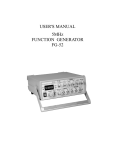
5MHz FUNCTION GENERATOR
MODEL GF-8056
User’s Manual
TM
Elenco Electronics, Inc.
TM
Copyright © 2004 by Elenco Electronics, Inc. All rights reserved.
No part of this book shall be reproduced by any means; electronic, photocopying, or otherwise without written permission from the publisher.
753117
NOTICE BEFORE OPERATION
1. Unpack the instrument:
Hints for operating the instrument:
Observe the following suggestions for successful
instrument operation.
After receiving the instrument, immediately
unpack and inspect it for any damage which
might have occured during transportation or
shortage of accessories. If any signs of damage
and/or shortage of accessories are found, notify
the dealer immediately.
1. Never place heavy objects on the instrument.
2. Never place a hot soldering iron on or near the
instrument.
3. Never insert wires, pins or other metal objects
into the ventilation fan.
2. Environments:
Normal operating temperature of the instrument
is 10°C to 40°C (50°F to 104°F). Operation of the
instrument outside of this temperature range may
cause damage to the circuits.
4. Never move or pull the instrument with power
cord or probe cord.
Never move the instrument especially when the
power cord or signal probe is connected to a
circuit.
Do not use the instrument in a place where
strong magnetic or electric fields exist. Such
fields may disturb the measurement.
5. If the instrument is used in a manner not
specified by the manufacturer, the protection
provided by the equipment may be impaired.
3. Check the Line Voltage:
! WARNING: The following precautions must
The instrument can operate on any one of the
line voltages shown in the table below by
inserting the line voltage selector plug in the
corresponding position on the rear panel.
Before connecting the power plug to an AC line
outlet, be sure to check that voltage selector plug
is set in the correct position corresponding to the
line voltage.
be observed to help prevent electric shock.
1. When the instrument is used for testing, there is
always a certain amount of danger from electrical
shock. The person using the instrument should
be a qualified electronics technician or otherwise
trained and qualified to work in such
circumstance.
2. Do not operate the instrument with the cover
removed unless you are a qualified service
technician.
! CAUTION: The instrument may not properly
operate or may be damaged if it is
connected to an AC line with the wrong
voltage. When line voltages are changed,
replacement of the fuses is also required.
Selector
Line Voltage
Fuse
115V
100~125V 50/60Hz
600mA
230V
220~240V 50/60Hz
300mA
3. The ground wire of the 3-wire AC power plug
places the chassis and housing of the instrument
at earth ground. Use only a 3-wire outlet, and do
not attempt to defeat the ground wire connection
or float the instrument. Doing so may pose a
great safety hazard.
4. Do not obstruct the ventilation holes in the rear
panel, as this will increase the internal
temperature.
5. Never apply an external voltage to the output
BNC connector of the instrument.
6. Excessive voltage applied to the input BNC
connector may damage the instrument.
-1-
GENERAL
DESCRIPTION
3. As a Sweep Generator:
The GF-8056 provides linear sweep or log
sweep. Use the selection switch to select the
sweep mode. Maximum sweep width 1:100 and
sweep speed 5sec to 10ms. Also, the GF-8056
provides VCF input and synchronous output
function. Easy-to-operate.
The GF-8056 is a deluxe function generator
combined with a 5-digit, high-resolution 60MHz
counter. The GF-8056 is a rugged, easy-tooperate, excellent heat dissipating and high
stability instrument.
The GF-8056 is a 4-in-1 instrument. It can be
used as the following described four kinds of
electronic instruments respectively:
4. As a Counter:
The GF-8056 is a 5-digit, micro-controlled
counter. The GF-8056 features auto-range, autogate time and high-resolution - 0.001Hz, input
impedance - 1MΩ, bandwidth - 0.2Hz~60MHz,
voltage resistance - 150Vp-p. Other features the
GF-8056 provides: adjustable trigger +2.5V with
LED indication. Display unit auto-indicate, HF /
LF selector, 100kHz filter.
1. As a Function Generator:
Eight waveforms selected by a rotary switch
instead of push-button to prevent accidental
touching or bad connections. Maximum output
20Vp-p (no load) and minimum output 0.1Vp-p
(no load).
2. As a Pulse Generator:
5. As a DC Voltage:
The GF-8056 provides positive pulse and reverse
negative pulse output with the Pull Reverse
Switch, maximum output 20Vp-p (no load).
Frequency display by the LED, pulse width from
0.4sec to 100ns. Can meet most audio, video
and other basic electronic application
requirements.
The GF-8056 provides a DC output function. The
output voltage can be adjusted from +10V to –10.
It can be used as a low-power DC source.
SPECIFICATIONS
1. General Specifications:
C. Common Specification
Operating temperature: 0°C~40°C,
10%~80% R.H.
Storage temperature: –20°C~70°C,
0%~90% R.H.
Power source: AC 115V (+10%) 50/60Hz,
FUSE: 600mA AC 230V
(+10%) 50/60Hz,
FUSE: 300mA
Power consumption: 25W
Ventilation: DC 12V / 100mA fan
Dimensions: 275 x 90 x 300mm
Weight: 2.5 kgs. net.
Accessory: Power cord, operation manual
A. Generator
Frequency: 0.05Hz~5MHz, display on 5-digit
LED display, maximum resolution
0.001Hz in 8 ranges.
Waveform output: Sine, square, triangle,
positive, ramp, negative
ramp, positive pulse and
negative pulse, DC, 8
waveforms.
Stability: 0.1%~15 minutes after switch “ON”
0.2%~24 hrs. after switch “ON”
DC offset: +10V (no load), +5V (50Ω load),
continuously adjustable,
controlled by an offset switch.
2. Triangle Wave:
B. Counter
Frequency: 0.05Hz~5MHz
Symmetry: 50% (rise wave) to 50% (fall
wave), < 1%, 1Hz~100kHz
Linearity: < 1%, (1Hz~100kHz)
Display: 5 digits 0.36” red LED
Max. resolution: 0.001Hz
Display unit: Hz/kHz automatically
controlled by CPU
-2-
SPECIFICATIONS (continued)
3. Sine Wave:
10. V.C.F. Input:
Frequency: 0.05Hz~5MHz
Input impedance: 0~10V
Distortion: < 1%, 1Hz~100kHz
Input frequency: DC~1kHz variable 1:1 to 1:100
Harmonic ratio: < 30dB, 100kHz~5MHz
11. Sweep Synchronous Output:
Frequency response: < 0.1dB, up to 100kHz
< 1.5dB, 100kHz to 5MHz
Output impedance: 1kΩ, < 2%
Output waveform: Linear or log sweep ramp wave
4. Square Wave:
Frequency: 0.05Hz~5MHz
Output amplitude: 10Vp-p (no load) or
5Vp-p (1kΩ load)
Symmetry: 50% (positive half) to 50% (negative
half). < 1%, 1Hz~100kHz
Output frequency: 0.2Hz~100Hz continuously
adjustable
Rise time: < 90ns (20Vp-p , no load)
12. Sweep Generator:
5. Ramp Wave:
Sweep form: Linear or log switchable
Frequency: 0.05Hz~4.5MHz, 8 range
selected by rotary switch
Sweep speed: 5sec~10ms, continuously
adjustable
Symmetry: 90% (rise wave) to 10% (fall wave),
continuously adjustable
Sweep width: 1:1~1:100
13. Counter:
Linearity: < 1%, (0.1Hz~100kHz)
Display: 5 digits, 0.36” red LED display
6. Positive Pulse:
Max. Resolution: 0.001Hz
Frequency: 0.05Hz~4.5MHz
Display unit: Hz / kHz autorange
Width: 0.4sec~100ns, continuously adjustable
Time base: 20MHz
Symmetry: 1:1 to 10:1 continuously adjustable
1Hz~100kHz
Temperature coefficient: < 20ppm / °C
Reverse: Pull the Rev. switch, the output will
become a negative pulse
Power supply: +5V, 160mA
Accuracy: <0.02% +1 digit
Internal Counter:
7. DC:
Range: Autorange with 4 resolution,
0.001Hz / 0.01Hz / 0.001kHz /
0.01kHz, auto-controlled by CPU
Output voltage: +10V to –10V continuously
adjustable by OFFSET switch
Display: 0.500Hz~5000.0kHz auto-select by
CPU
8. Main Output:
Output impedance: 50Ω, < 2%
Gate time: Variable, 0.25sec~5sec,
auto-setting
Max. output: 20Vp-p (no load), +1Vp-p
10Vp-p (50Ω load) +0.5V
Min. display digits: 4 digits
Min. output: 0.1Vp-p (no load),
or 0.05Vp-p (50Ω load)
External Counter:
Max. input voltage: < 150Vrms
Attenuator: One –26dB (1/20) attenuator,
< 2% accuracy
Input impedance: 1MΩ, < 2%
Input frequency: 0.2Hz ~60MHz
9. Synchonous Output:
Coupling: HF - 100kHz and greater
LF - 100kHz and lower
Output impedance: 50Ω, < 2% accuracy
Output level: TTL level, > 3Vp-p fixed amplitude
Min. display digits: 4 digits
Fan out: >20
Gate time:
Rise time: <60nS
0.25sec~10sec, auto-setting
depends on the input frequency
Sensitivity: > 30mVrms (1MHz)
-3-
FRONT PANEL DESCRIPTION
14
13
12
11
10
9
8
7
6
15
5
1
2
16
17
18
1. Power Switch: Pushing the switch “ON” will light the LED
digits (14) to indicate power “ON”.
19
4
3
12. Hz: The lit LED indicates the display units are “Hz”.
13. kHz: The lit LED indicates the display units are “kHz”.
2. Frequency: Turn the switch to set the desired frequency
generated. This knob is for micro-adjust.
14. LED Digits: 5 digits indicates the frequency generated or
the EXT input. The units will be indicated by
(12) or (13) selected by CPU automatically.
3. Synchronous Output: TTL level square wave signal.
Output frequency as MAIN output.
15. EXT. Counter: The red LED indicates Ext. counter
condition.
LED lit - trigger level too high.
LED dark - trigger level too low.
LED flashing - triggering state.
4. Sweep Output: Sweep signal output BNC. It will operate
individually whether the instrument set to
sweep mode operation or not, output
impedance of 1kΩ, output amplitude 10Vp-p,
output signal: Linear or Log.
16. Display: Selects the source of the frequency displayed by
(14).
5. Main Output: Waveform selected by Function switch. Max.
output impedance 50Ω. Max. amplitude
20Vp-p (no load).
INT Hz / kHz - Display the frequency of the signal
generated by the GF-8056.
6. Amplitude: Turn switch to adjust the amplitude of the output
signal. Pull out the switch to attenuate the
output 20 times (or –26dB).
EXT HF - Display the external input high frequency
signal. This position filters out the DC signal
and low frequency harmonic signal. Inputs only
the expected high frequency signal.
7. DC Offset: The switch is set to OFF position in normal
operation. When used for BIAS circuit, pull “ON”
the switch and turn to adjust DC offset voltage.
EXT LF - 100kHz Filter - Display the external input low
frequency signal. Set to this
position filters out the signal
higher than 100kHz making the
low frequency signal more stable.
8. Sweep Rate: Rotate switch to adjust the sweep rate from 5sec
to 10mS at the Sweep Output (4). Pull switch to
synchronous output signals from (4) and (5).
17. RAMP / PULSE: Rotate switch to generate a RAMP wave
from a Triangle wave and a PULSE
wave from a Square wave. Pull switch
out to Invert position, output will be
negative Ramp and negative Pulse.
9. Sweep Width: The switch is operational only when switch
(8) is set to “ON”. Rotate the switch to adjust
the sweep width. In the normal position
(switch in), the unit is set to “Linear Sweep”.
Pull the switch out for the “ON” position, set
the unit to “Log Sweep”.
18. EXT Input: External signal input BNC.
The input
frequency is 0.2Hz to 60MHz, max. input
voltage 150Vrms [when (17) is at “PULL”
position].
10. Function Wave Selector: Rotate switch to select
between
four
output
waveforms:
sine, triangle,
square, and DC.
19. V.C.F. Input: External input DC signal to control the
frequency generated.
External input AC sweep signal to make it
external sweep.
External input AC sine wave to make it
external FM modulation.
Input signal 0~10V, < 1kHz.
Input impedance - 1kΩ.
11. Frequency Range: Selects output frequency range by
rotating switch.
The frequency
displayed on (14) will be the product of
the selected digits by (2) and (11).
The frequency will be 10 times
difference on each step. Four ranges:
x1, x10, x100, x1000.
-4-
OPERATING INSTRUCTIONS
WARNING: Before applying power to your GF-8056, make sure that the input voltage setting is correct for your
power source.
CAUTION: All the knobs are set to “PUSH” position on operation if not special marked to be set at “PULL”.
(A) Function Generator and Inspection
4
5
7
6
1
3
2
6. Turn the AMPLITUDE knob to adjust the
amplitude of the signal output to CH1. When you
“PULL” out the switch, the amplitude will be
reduced 20 times (–20dB), but the display of CH2
(sync output signal) will be unchanged.
1. Turn on the power switch and make sure the
LED’s of the 5-digit display light.
2. Connect MAIN OUTPUT BNC of the GF-8056 to
CH1 input BNC of your Oscilloscope, and the
SYNC OUTPUT BNC to CH2. Set the trigger
source of your oscilloscope to CH2.
7. Turn the OFFSET knob. You will find that CH1
and CH2 will not change. This switch will operate
only in the “PULL” position. PULL out the offset
switch and turn it to set DC offset voltage (from
+10V to –10V) of the main output signal. Note
that the SYNC output signal will be not affected.
3. Turn the FREQUENCY knob from x0.05~x5.0
The GF-8056 display and oscilloscope will be
changed slightly on each step.
4. Turn the RANGE knob from x1~x1000. You will
find the 5-digit LED display value will change 10
times on each step and the oscilloscope too.
When the switch (7) is set at Hz or kHz, the
display value will be changed to x1 or x1000.
Note: When the offset voltage is higher than the
wave (+ or –), the display waveform will be cut OFF.
5. Turn the FUNCTION knob to select the waveform
output to CH1 of your Oscilloscope. CH2 will be
TTL square wave only.
-5-
(B) Sweep Generator
7
6
5
4
6
1
8
3
2
1. Turn on the power switch and make sure the
LED’s of the 5-digit display light.
6. The AMPLITUDE and FUNCTION knobs will
operate as a generator.
2. Connect the main OUTPUT BNC to the CH1
input BNC of your oscilloscope.
7. The frequency shown on the 5-digit LED display
is the generator’s before “PULL SWEEP ON”.
This frequency will be the start frequency. After
“PULL SWEEP ON”, the sweep condition,
including frequency, waveform, sweep mode,
etc., will be observed from the CRT of the
oscilloscope. The 5-digit LED display will
continuously vary.
3. Connect the SWEEP OUTPUT BNC to the CH2
input BNC of your oscilloscope and set the
trigger source of the oscilloscope at CH2.
4. Turn the SWEEP RATE knob. CH2 of the
oscilloscope will display a linear sawtooth wave
and the frequency will be variable from 5sec to
10mS by turning the switch. CH1 will display the
wave according to the FUNCTION switch
position. PULL out the switch to set “SWEEP
ON”. The display of CH2 will be unchanged and
the display frequency will be varied by turning the
knobs. Note that the display of CH1 will be a
sweep wave, and the speed will depend on the
sweep rate.
8. V.C.F. INPUT - Set the sweep rate switch at the
“PUSH” position to set the GF-8056 at normal
generator mode. Connect the sweep output BNC
to V.C.F. INPUT BNC and check the waveform
displayed on CH1 of the scope. The waveform
displayed should be the sweep wave. When
inputting a sine wave from another generator to
the V.C.F. INPUT to observe the FM display, be
sure the frequency of the basic wave (GF-8056)
is higher than the external input signal.
NOTE: After “PULL SWEEP ON”, the trigger
source of the oscilloscope must be changed from
CH2 to CH1.
5. Turn the SWEEP WIDTH knob to adjust the
sweep width display on CH1.
NOTE: Be sure that the SWEEP RATE SWITCH
was at the “PULL” position. When pulling out the
sweep width switch, the sweep mode will change
from linear to log sweep. The waveform display of
CH1 will become log form.
-6-
(C) Pulse Wave Generator
5
4
9
8
1
6
3
1. Turn on the power switch and make sure the
LED’s of the 5-digit display light.
2
6. Set the pulse width by adjusting the knob (6).
7. Pull the knob (6) to display the negative pulse
position.
2. Connect the MAIN OUTPUT BNC to CH1.
3. Connect the SYNC OUTPUT BNC to CH2 and
set the trigger source of the oscilloscope on CH2.
8. Turn the AMPLITUDE knob to adjust the
amplitude of the signal output from the main
output BNC (2). The signal will be –26dB when
you “PULL” out the switch. But the signal output
from the “SYNC” output BNC (3) will not be
affected by this switch. The output signal of the
“SYNC” output will keep at a TTL level.
4. Set the FUNCTION knob to the square wave
position (
) and turn the knob (6) until the
display becomes the pulse waveform you want.
5. Set the FREQUENCY and RANGE to the desired
frequency.
9. Set the DC offset voltage by pulling out the
“OFFSET” switch. Turn switch to adjust the DC
offset voltage from +10V to –10V.
-7-
(D) Frequency Counter
2
3
1
4
3
1. Turn on the power switch and make sure the
LED’s of the 5-digit display light.
3. Connect the EXT INPUT BNC to the external
signal source, the EXT LED lights.
2. DISPLAY: The coupling provides 4 steps.
4. Display unit: The display unit of the GF-8056 will
be on Hz or kHz automatically controlled by CPU.
(a). INT/Hz: To use the internal counter from
0.05Hz to 5kHz.
(b). INT/kHz: To use the internal counter from
0.5kHz to 5MHz.
(c). EXT HF: To use the external counter for
high frequency (100kHz to
60MHz).
(d). EXT LF: To use the external counter for
low frequency (0.2Hz to
100kHz).
-8-
-9-
-10-
TM
Elenco Electronics, Inc.
150 W. Carpenter Avenue
Wheeling, IL 60090
(847) 541-3800
Website: www.elenco.com
e-mail: [email protected]