1
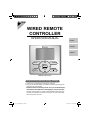
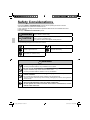
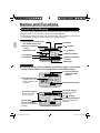
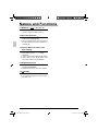
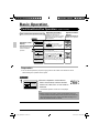
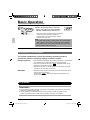
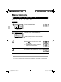
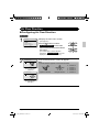
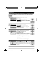
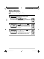
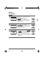
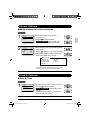
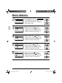
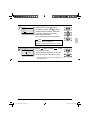
WIRED REMOTE CONTROLLER OPERATION MANUAL English Français Español Mode On/Off Menu OK Fan Speed Cancel MODEL BRC1E71 Proper Use for Effective Energy Savings ● Thank you for purchasing the wired remote controller. ● This manual describes safety consideration which should be observed during the use of the product. Read this manual carefully and be sure you understand the information provided before attempting to use the product. Keep this manual where it is readily accessible after reading it through. If another user operates the product in the future, be sure to hand over this manual to the new user. 00_CV_3P243520-2C.indd 1 8/27/2009 1:47:19 PM Utilisation Correcte pour des Économies d’Énergie Efficaces ● Nous vous remercions pour votre achat de la télécommande câblée. ● Ce manuel décrit les précautions de sécurité à respecter lors de l’utilisation du produit. Lisez soigneusement ce manuel et veillez à bien comprendre les renseignements fournis avant d’utiliser le produit. Gardez ce manuel dans un endroit facile à accéder après l’avoir lu complètement. Si un autre utilisateur doit faire fonctionner le produit par la suite, veillez à remettre ce manuel au nouvel utilisateur. Uso apropiado para ahorro de energía efectivo ● Gracias por su compra del control remoto alámbrico. ● Este manual describe las consideraciones de seguridad que deben ser observadas durante el uso del producto. Lea cuidadosamente este manual y asegúrese de comprender la información provista antes de intentar usar el producto. Guarde este manual en un lugar fácilmente accesible después de leerlo completamente. Si otro usuario opera el producto en el futuro, asegúrese de entregar este manual al nuevo usuario. 00_CV_3P243520-2C.indd 2 8/27/2009 1:47:21 PM Contents Notices Safety Considerations Items to be Strictly Observed ...... 2 Button Locations and Descriptions ........................... 4 Basic Operation Cool/Heat/Auto/Fan Operation .............................. 10 Dry Mode ............................................................... 12 Setback .................................................................. 14 Ventilation Mode .................................................... 15 Setting the Cool / Heat Changeover Master ........... 16 Key Lock ............................................................... 18 Quick Reference Main Menu Items ................................................... 20 Menu Options Moving Within the Main Menu Screen ................... 22 Air Flow Direction ................................................... 23 Ventilation .............................................................. 26 Schedule ................................................................ 28 Off Timer ................................................................ 33 Maintenance Information ....................................... 35 Configuration .......................................................... 36 Current Settings ..................................................... 39 Clock & Calendar ................................................... 39 Language ............................................................... 42 Maintenance Reset Filter Indicator .............................................. 43 Maintaining the Unit and LCD Display ................... 44 Reference Information Error Code Display ................................................. 45 After-sale Service ................................................... 46 English 01_EN_3P243520-2C.indd 1 1 8/27/2009 1:48:26 PM Safety Considerations Read these SAFETY CONSIDERATIONS carefully before operating the remote controller. Train the customer to operate and maintain the unit. Inform customers that they should store this Operations Manual with the Installation Manual for future reference. Meanings of WARNING and CAUTION Symbols: WARNING Indicates a potentially hazardous situation which, if not avoided, could result in death or serious injury. CAUTION Indicates a potentially hazardous situation which, if not avoided, may result in minor or moderate injury. It may also be used to alert against unsafe practices. ● The following pictograms are used in this manual. Never do. Always follow the instructions given. Be sure to ground the unit. Keep wet hands away. Keep water and moisture away. WARNING ● Do not modify or repair the remote controller. Consult your Daikin dealer for any modification or for repairs. ● Do not relocate or reinstall the remote controller by yourself. Improper installation may result in electric shocks or fire. Consult your Daikin dealer to relocate or for any reinstallation. ● Do not use flammable materials (e.g., hairspray or insecticide) near the remote controller. Do not clean the product with organic solvents such as paint thinner. The use of organic solvents may cause cracking, damaging the product, causing electric shocks, or fire. ● Consult the dealer if the remote controller was submerged under water due to a natural disaster, such as a flood or hurricane. Do not operate the remote controller at this time or a malfunction, electric shock, or fire can occur. 2 01_EN_3P243520-2C.indd 2 English 8/27/2009 1:48:26 PM ――Items to be Strictly Observed―― CAUTION ● Do not allow children to play with the remote controller to avoid causing damage to the product. ● Never disassemble the remote controller. Touching the interior parts may result in electric shocks or fire. Consult your Daikin dealer for internal inspections and adjustments. ● Do not touch the remote controller buttons with wet fingers. Touching the buttons with wet fingers can cause an electric shock. ● Do not wash the remote controller. Doing so may cause electric leakage and result in electric shocks or fire. ● Never let the remote controller to get wet. Water can cause damage to the remote controller, and may cause an electric shock or fire. English 01_EN_3P243520-2C.indd 3 3 8/27/2009 1:48:27 PM Button Locations and Descriptions 1. Operation mode selector button 11. LCD (with backlight) 4. Up button 5. Down button 6. Right button 7. Left button 9. Operation lamp Mode On/Off 3. Menu/OK button Menu OK Fan Speed 8. On/Off button Cancel 10. Cancel button 2. Fan speed control button Functions other than basic operation items (i.e., On/Off, Operation mode selector, Fan speed control, and temperature setpoint) are set from the menu screen. NOTE ● Do not install the remote controller in places exposed to direct sunlight, otherwise the LCD will be damaged. ● Do not pull or twist the remote controller cord, otherwise the remote controller may be damaged. ● Do not use objects with sharp ends to press the buttons on the remote controller otherwise damage may result. 4 01_EN_3P243520-2C.indd 4 English 8/27/2009 1:48:27 PM 1. Operation mode selector button ● Press this button to select the operation mode of your preference. (See page 10.) * Available modes vary with the indoor unit model. 2. Fan speed control button ● Press this button to select the fan speed of your preference. (See page 11.) * Available fan speeds vary with the indoor unit model. 3. Menu/OK button ● Used to indicate the main menu. (See page 20 for the menu items.) ● Used to enter the selected item. 4. Up button ● Used to raise the setpoint. ● The item above the current selection will be highlighted. (The highlighted items will be scrolled continuously when the button is continuously pressed.) ● Used to change the selected item. 5. Down button 7. Left button ● Used to highlight the next items on the left-hand side. ● Each screen is scrolled in the left-hand direction. 8. On/Off button ● Press this button and system will start. ● Press this button again to stop the system. 9. Operation lamp (Green) ● This lamp illuminates solid during normal operation. ● This lamp blinks if a error occurs. 10.Cancel button ● Used to return to the previous screen. 11. LCD (with backlight) ● The backlight will be illuminated for approximately 30 seconds by pressing any button. ● If two remote controllers are used to control a single indoor unit, only the controller to be accessed first will have backlight functionality. ● Used to lower the setpoint. ● The item below the current selection will be highlighted. (The highlighted items will be scrolled continuously when the button is continuously pressed.) ● Used to change the selected item. 6. Right button ● Used to highlight the next items on the right-hand side. ● Each screen is scrolled in the right-hand direction. English 01_EN_3P243520-2C.indd 5 5 8/27/2009 1:48:28 PM Names and Functions Liquid Crystal Display ● Two types of liquid crystal display (LCD) are available. The standard display is set by default. ● Detailed display can be selected in the main menu. (See page 37.) ● The displayed contents of the screen vary with the operation mode of the indoor unit model. (The following display will appear when the indoor unit is in automatic operation.) Standard display 10.Changeover controlled by the master indoor unit 9.Under centralized control 1.Operation mode 2.Fan Speed 6.Ventilation 11.Setback 8.( ) display CENTRAL CONTROL Auto MASTER CONTROLLED SETBACK Set to Cool 74F Heat 70F STANDBY ERV PURIFY This function is not available AUTO AIR <Standard display example> 7.( ) display 3.Setpoint display 4.Stand by for Defrost/ Hot start 5.Message Detailed Display The air flow direction, clock, and detailed selection items appear on the detailed display screen in addition to the items appearing on the standard display. CENTRAL CONTROL 12.Air Flow Direction (Displayed only when the air conditioner is in operation.) Auto MASTER CONTROLLED Fri SETBACK 11:03A Room 74F AUTO AIR ERV PURIFY Return Set to Cool 74F Heat 70F STANDBY 13.Current Day/time (12/24 hour time display) 14.Detailed selection Setting <Detailed display example 1> No Clock display No Fan speed display (with no fan speed control function) CENTRAL CONTROL Auto MASTER CONTROLLED SETBACK --:-- (when the clock has not been set) 15. ( ) display No Detailed item display No Air Flow Direction display (with no air flow direction settings) 6 01_EN_3P243520-2C.indd 6 AUTO AIR ERV PURIFY Return STANDBY (with no detailed items selected) Setting <Detailed display example 2> English 8/27/2009 1:48:28 PM 1. Operation mode “Error: Push Menu button” “Warning: Push Menu button” ● Displayed if an error or warning is detected (see page 45). ● Used to display the current operation mode: Cool, Heat, Vent, Fan, Dry or Auto. “Time to clean filter” “Time to clean element” “Time to clean filter & element” ● Displayed as a reminder when it is time to clean the filter or element (see page 43). 2. Fan Speed ● Used to display the fan speed that is set for the indoor unit. ● The fan speed will not be displayed if the connected model does not have fan speed control functionality. 6. Ventilation ● Displayed when a energy recovery ventilator is connected. ● Ventilation Mode icon.“ AUTO ERV ERV BYPASS ” These icons indicate the current ventilation mode (ERV only) (AUTO, ERV, BYPASS). ● Air Purify ICON “ AIR PURIFY ” This icon indicates that the air purifying unit (option) in operation. 3. Setpoint display ● Used to display the setpoint for the indoor unit. ● Use the Celsius/Fahrenheit item in the main menu to select the temperature unit (Celsius or Fahrenheit). 4. Stand by for Defrost/Hot start “ STANDBY ” (See page 12.) If ventilation icon is displayed in this field: ● Indicates that an energy recovery ventilator is connected. For details, refer to the Operation Manual of the ERV. 5. Message The following messages may be displayed. “This function is not available” ● Displayed for a few seconds when an operation button is pressed and the indoor unit does not provide the corresponding function. ● In a remote control group, the message will not appear if at least one of the indoor units provides the corresponding function. English 01_EN_3P243520-2C.indd 7 7. display (See page 18.) ● Displayed when the key lock is set. 8. display (See page 28.) ● Displayed if the Schedule or Off timer is enabled. 9. Under Centralized control “ CENTRAL CONTROL ” ● Displayed if the system is under the management of a multi zone controller (option) and the operation of the system through the remote controller is limited. 10.Changeover controlled by the master indoor unit “ ” MASTER CONTROLLED (VRV only) ● Displayed when another indoor unit on the system has the authority to change the operation mode between cool and heat. 7 8/27/2009 1:48:29 PM Names and Functions 11. Setback “ SETBACK ” (See page 14.) ● The setback icon flashes when the unit is turned on under the setback control. 12.Air Flow Direction “ ” ● Displayed when the air flow direction and swing are set (see page 23). ● If the connected indoor unit model does not include oscillating louvers this item will not be displayed. 13.Current Day/Time (12/24 hour time display) ● Displayed if the clock is set (see page 39). ● If the clock is not set, “ -- : -- ” will be displayed. ● 12 hour time format is displayed by default. ● Select 12/24 hour time display option in the main menu under “Clock & Calendar”. 14.Detailed selection ● Displayed if the detailed display item is selected (see page 38). ● Detailed items are not selected by default. 15. display ● Displayed when the clock needs to be set. ● The schedule function will not work unless the clock is set. 8 01_EN_3P243520-2C.indd 8 English 8/27/2009 1:48:30 PM English 01_EN_3P243520-2C.indd 9 9 8/27/2009 1:48:30 PM Basic Operation Cool/Heat/Auto/Fan Operation How to follow the operation manual Operation 1 Operation screen display Main Menu 1/2 Air Flow Direction Ventilation Schedule Off Timer Celsius / Fahrenheit Maintenance Information Setting Describes screens that will be displayed on the remote controller in operation. 2 (SkyAir and VRV) Operation procedure Explains the sequence of operation for the remote controller. Operate the buttons according to the procedure. Operation button display Displays the location of buttons to be operated. ● Display the main menu screen. (See page 22.) ● Press buttons to select Schedule the main menu screen. Press Menu/OK button to display the timer screen. Schedule Clock has not been set. Would you like to set it now? Yes No Setting Date & Time Year 2008 Month 01 Day 01 Tuesday 12:00 A ● Before setting the schedule , the clock must be set. ● If the clock has not been set, a screen like the one on the left will appear. Press buttons to select Yes and press Menu/OK button. ● The date & time screen will appear. ● Set the current year, month, day, and time. (See clock settings on page 39.) Setting Preparation ● For mechanical protection purposes, apply power to the outdoor units at least six hours before starting the operation of the system. Operation 1 Cool Return Set to Cool 74F Setting ● Press the Operation mode selector button several times until the desired mode Cool, Heat, Fan, or Auto mode is selected. * Unavailable operation modes are not displayed. Note ● Before changing the mode, confirm that the display does not indicate master controlled status. Both heat and cool mode may not be selected if the unit is master controlled. See page 16 if MASTER CONTROLLED icon blinks. 10 01_EN_3P243520-2C.indd 10 English 8/27/2009 1:48:30 PM 2 On/Off nu K 3 Cool Set to Cool 74F Return Setting ● Press On/Off button. The Operation lamp (green) will illuminate and the system will start operating. ● The setpoint will increase by 1°F (or 1°C) when button is pressed and decrease by 1°F (or 1°C) when button is pressed. * Setpoint is not available in fan or dry mode. 4 Cool Set to Cool 74F Return Setting Low Medium High 5 ● To change the fan speed, press the Fan speed control button and select the desired fan speed from Low, Medium or High. * Only two fan speed adjustment levels, low and high may be available depending on the type of indoor unit. * The system may be in automatic fan speed control for equipment protection purposes. * The system may be in automatic fan speed control according to the room temperature. It is normal for the fan to intermittently stop operating. * It is normal for a delay to occur when changing the fan speed. ● Adjust Air Flow Direction from the main menu (see page 23). * If the connected indoor unit model does not include oscillating louvers this function will not be available. English 01_EN_3P243520-2C.indd 11 11 8/27/2009 1:48:31 PM Basic Operation 6 On/Off nu K ● When the On/Off button is pressed again, the system will stop operating and the operation lamp will turn off. * When the system is stopped while in the heating mode, the fan will continue to operate for approximately one minute to remove residual heat from the indoor unit. Note ● To prevent water damage or system failure, do not immediately remove power from the indoor unit following system operation. Wait at least five minutes for the condensate pump to finishing draining residual water from the unit. Characteristics of Heat Mode The system automatically controls the following operating modes to prevent the reduction of heating capacity and space comfort. Defrost operation ● The system will automatically go into defrost operation to prevent frost accumulation at the outdoor unit and loss of heating capacity. ● The indoor unit fan will stop, and “ STANDBY ” (Defrost/Hot start) will be displayed on the remote controller. ● The system will return to normal operation usually within six to eight minutes (but not more than 10 minutes). Hot start ● When the system goes into heat mode, the indoor unit fan will stop in order to prevent a cold draft. (In that case, “ STANDBY ” (Defrost/Hot start) will be displayed on the remote controller.) Dry Mode Preparation ● For equipment protection purposes, apply power to the outdoor units at least six hours before starting the operation of the system. ● The dry mode may not be selected if the remote controller is master controlled and the system is not already in the cooling mode of operation. (see page 17 for details) 12 01_EN_3P243520-2C.indd 12 English 8/27/2009 1:48:32 PM Operation 1 ● Press Mode button several times until the Dry mode is selected. Dry Return 2 Setting On/Off nu K * The dry mode may not be available depending on the type of indoor unit. ● Press On/Off button. The Operation lamp (green) will illuminate and the system will start operating. * In Dry mode, the system maintains automatic temperature and fan speed control. Therefore, temperature setpoint or fan speed settings are not available while the indoor unit is in the Dry mode. 3 ● Adjust Air Flow Direction from the main menu (see page 23). * If the connected indoor unit model does not include oscillating louvers this function will not be available. 4 On/Off nu K ● When the On/Off button is pressed again, the system will stop operating and the operation lamp will turn off. Note ● To prevent water damage or system failure, do not immediately remove power from the indoor unit following system operation. Wait at least five minutes for the condensate pump to finishing draining residual water from the unit. English 01_EN_3P243520-2C.indd 13 13 8/27/2009 1:48:33 PM Basic Operation Characteristic of Dry mode The Dry mode dehumidifys the space at reduced cooling capacity to prevent the room temperature from dropping to uncomfortable levels. Setback The Setback feature will maintain the space temperature in a specific range during unoccupied periods. Note ● This function will temporarily start an indoor unit that was previously turned off by the user or turned off from a schedule event / off timer. ● This function must be enabled by the system installer. Operation 1 Cool Return Setback Cool 84F ● The setback icon flashes when the unit is turned on under the setback control. Setting SETBACK Cool Return 14 01_EN_3P243520-2C.indd 14 Setback Cool 84F Setting English 8/27/2009 1:48:33 PM Ventilation Mode When the Indoor Unit is Interlocked with Energy Recovery Ventilator Preparation ● For equipment protection purposes, apply power to the outdoor units at least six hours before starting the operation of the system. Operation 1 Vent AUTO ERV Return Setting 2 ● When operating the energy recovery ventilator (ERV) between seasons without the air conditioner, set the control to ventilation mode. ● Changes to the ventilation mode are made from the main menu. * Ventilation Mode: Auto, ERV, and Bypass 3 ● Changes to the ventilation rate are made from the main menu. * Ventilation Rate: Low or High 4 On/Off ● Press On/Off button. The Operation lamp (green) will illuminate and the system will start operating. On/Off ● When the On/Off button is pressed again, the system will stop operating and the operation lamp will turn off. nu K 5 nu K English 01_EN_3P243520-2C.indd 15 15 8/27/2009 1:48:34 PM Basic Operation Setting the Cool / Heat Changeover Master (VRV only) Setting Changes 1 Cool See page 18 for an explanation of the cool/heat changeover master indoor unit. Set to Cool 74F Return Setting ● Press the Operation Mode Selector button on the remote controller of the changeover master indoor unit for at least four seconds. (While the backlight is illuminated) ● The “ ” icon on each remote controller for the indoor units connected to the same outdoor unit or BS unit will start flashing. MASTER CONTROLLED MASTER CONTROLLED Cool Set to Cool 74F Return Setting * Vent mode setting changes are possible regardless of the cool/ heat changeover master indoor unit. * If cool/heat mode is configured for control from the outdoor unit, all remote controllers serving the associated indoor units will MASTER display its “ CONTROLLED ” icon. ● Set the cool/heat changeover master indoor unit as outlined below. Selection Settings 2 The icon “ MASTER CONTROLLED Cool Return Cool Return Set to Cool 74F Setting Set to Cool 74F Setting MASTER CONTROLLED ” will flash on all remote controllers when the power is turned ON for the first time. ● Press the Mode Selector button on the remote controller of the indoor unit which is to serve as the cool/heat changeover master. The remote controller for the changeover master indoor unit is established and the icon disappears. Other remote controllers in the system (indoor units served by the same outdoor unit or indoor units served by the same branch selector (BS) unit) will now display the icon. MASTER CONTROLLED MASTER CONTROLLED 16 01_EN_3P243520-2C.indd 16 English 8/27/2009 1:48:35 PM 3 Cool Return Set to Cool 74F Setting ● Press the Mode button on the remote controller of the indoor unit designated as the cool/heat changeover master (the remote controller not displaying the icon) repeatedly until the desired mode is selected. The display will change to “Fan”, “Dry”, “Auto”, “Cool”, “Heat” each time the button is pressed. ● Simultaneously, the other indoor units on the system will follow suit and change modes to reflect the new mode selected at the changeover master remote controller. MASTER CONTROLLED Cool / Heat Mode Selection Availability ● “Cool”, “Heat” and “Auto” are all only available for selection on the cool/heat changeover master indoor unit. The following table indicates the available operating modes of the other indoor units on the system based upon the selected mode of the master indoor unit. When the master indoor unit is set to The other indoor units in the system can be set to Cool Dry Heat Fan Cool mode Dry mode Heat mode Fan mode Auto mode (Cooling operation) Auto mode (Heating operation) English 01_EN_3P243520-2C.indd 17 17 8/27/2009 1:48:36 PM Basic Operation Precautions for Selecting the Cool / Heat Changeover Master Indoor Unit ● The cool/heat changeover master must be set for a single indoor unit in the following applications (2-Pipe Heat Pump System) (3-Pipe Heat Recovery System) BS unit: The BS unit is used for cooling or heat mode selection. Indoor unit Indoor unit A number of indoor units are connected to a single outdoor unit. A number of indoor units are connected to a single BS unit. Set any one of the indoor units as the cool/heat changeover master. Set any one of the indoor units as the cool/heat changeover master. Key Lock Operation 1 Confirm and cancel Key Lock settings in the basic display screen. Cool Return Set to Cool 74F ● Press the Menu/OK button for at least four seconds. (While the backlight is illuminated) Setting Basic screen 2 Cool Return 18 01_EN_3P243520-2C.indd 18 Set to Cool 74F Setting ● “ ” will appear. All buttons are disabled when the keys are locked. ● To cancel the key lock mode, continue pressing Menu/OK button for at least four seconds. (While the backlight is illuminated) English 8/27/2009 1:48:40 PM English 01_EN_3P243520-2C.indd 19 19 8/27/2009 1:48:45 PM Quick Reference The main menu has the following items. Menu item Air Flow Direction Description Used to configure air flow direction settings. ● The air flow direction louver is automatically operated up and down (left and right). ● The fixed air flow directions are configurable for five positions. Reference page 23 * This function is not available on all models. Ventilation Ventilation operation settings for energy reovery ventilator Schedule Ventilation Rate Used to set “Low” or “High” 26 Ventilation Mode Used to set Auto, ERV, or Bypass. 27 Daily Patterns ● Day settings are selected from three patterns, i.e., “7Days”, “Weekday/Weekend”, and “Weekday/Sat/ Sun”. 29 Settings ● Set the startup time and operation stop time. ON: Startup time, cooling and heating temperature setpoints can be configured. OFF: Operation stop time, cooling and heating setback temperature setpoints can be configured. ( --: Indicates that the setback function is disabled for this time period. ) _: Indicates that the temperature setpoint and setback temperature setpoint for this time period is not specified. The last active setpoint will be utilized. ● Up to five actions can be set for each day. 30 Off Timer Used to set each operation period of the system. ● Possible to set in 10 minute increments from 30 to 180 minutes. 33 Celsius / Fahrenheit ● Used to select whether temperature values will be displayed in Celsius or Fahrenheit. – Maintenance Information Used to display the maintenance information. 35 20 01_EN_3P243520-2C.indd 20 English 8/27/2009 1:48:45 PM Menu item Configuration Contrast Adjustment Display Standard or Detailed Display Description Reference page Used to make LCD contrast adjustment. ● Display mode Standard or detailed display ● Detailed display provides the choice to display between Room Temp, Outside Air Temp, System or None. Current Settings ● Used to display a list of current settings for available items. Clock & Calendar Used to configure date and time settings and corrections. Date & time 36 Used to set standard or detailed display mode. 37 39 ● The default time display is 12H. ● The clock will maintain accuracy to within ±30 seconds per month. ● If there is a power failure for a period not exceeding 48 hours, the clock will continue working with the built-in backup power supply. 12H/24H Clock 39 The time can be displayed in either a 12 hour or 24 hour time format. 42 Daylight Saving Time Used to adjust the clock in observance of daylight saving time. – Language The display language can be selected between English, Francais or Espanol. 42 Note: Available setting items vary with the indoor unit model. Sub Remote Controller Menu Items Indoor unit If two remote controllers are in control of a single indoor unit, the following menu items are not set in the sub remote controller. In this case, the following items should be configured in the main remote controller. ● Schedule ● Off timer ● Setback English 01_EN_3P243520-2C.indd 21 Outdoor unit Two remote controllers in control 21 8/27/2009 1:48:45 PM Menu Options Moving Within the Main Menu Screen Display Method for Main Menu Operation 1 ● Press Menu/OK button. Cool Set to Cool 74F Return Setting Basic screen 2 Main Menu 1/2 Air Flow Direction Ventilation Schedule Off Timer Celsius / Fahrenheit Maintenance Information Setting Main menu screen 3 ● The main menu screen will appear. Instructions for moving within the main menu will appear. ● Selecting items from the main menu. 1. Press buttons to select the desired item to be set. 2. Press Menu/OK button to display the details for the selected item. 4 ● To go back to the basic screen from the main menu, press the Cancel button. Note ● If a button is not pressed for 5 minutes during configuration, the controller will automatically revert to the basic screen. 22 01_EN_3P243520-2C.indd 22 English 8/27/2009 1:48:46 PM Air Flow Direction Configuring Air Flow Direction Operation 1 Main Menu 1/2 Air Flow Direction Ventilation Schedule Off Timer Celsius / Fahrenleit Maintenance Information Setting ● Display the main menu screen. (See page 22.) ● Press buttons to select Air Flow Direction on the main menu screen and press the Menu/ OK button. (For models with no airflow direction adjustment, Air Flow Direction will not be displayed on the main menu screen.) 2 Air Flow Direction ● The air flow direction screen will appear. Note ● Air flow direction appears on the screen as below. Swing Setting Air Flow Direction (up/down) Air Flow Direction 0 1 0 2 3 4 Up/down direction 4 1 2 3 Left/right direction 0 1 2 3 4 : Position : Position : Position : Position : Position 0 1 2 3 4 Swing Setting Air Flow Direction (left/right) English 01_EN_3P243520-2C.indd 23 23 8/27/2009 1:48:47 PM Menu Options 3 Air Flow Direction Swing Setting Left/right direction Air Flow Direction Swing Setting Up/down direction 4 ● Pressing buttons changes the setting to (in order) Swing , Position 0 , Position 1 , Position 2 , Position 3 , and Position 4 . ● Selecting Swing will cause the air flow direction louver to oscillate back and forth. For the swing setting only, all positions will be displayed. ● When you select positions 0 to 4, the louver will stay in a fixed position. Air Flow Direction Position 2 Setting Left/right direction Air Flow Direction Position 2 Cool20°C Heat15°C Setting * The illustration is an example of the display when position 2 is selected. ● Press buttons to select the desired air flow direction. Press Menu/OK button to return to the basic screen. Up/down direction 24 01_EN_3P243520-2C.indd 24 English 8/27/2009 1:48:47 PM Operational Details and Functions There are two types of air flow direction settings. Air flow direction swing The louvers automatically oscillate up and down. Indoor unit (Automatic) Air flow direction You can select from one of five fixed directions. (This has no relation to the angle of the louvers.) Indoor unit (Automatic) (Desired position) (Desired position) Movement of air flow direction louver Under the operating conditions shown below, air flow direction is controlled automatically. Actual operation may be different than what is displayed on the remote controller. Operating condition English 01_EN_3P243520-2C.indd 25 ● Room temperature is higher than the remote controller’s setpoint (in heating operation). ● When defrosting (in heating operation). (The air flow discharges horizontally to avoid creating a draft for the room occupants.) ● Under continuous operation with the air flow discharging horizontally. 25 8/27/2009 1:48:48 PM Menu Options Ventilation Ventilation screen display properties Operation 1 Main Menu 1/2 Air Flow Direction Ventilation Schedule Off Timer Celsius / Fahrenheit Maintenance Information Setting Ventilation Ventilation Rate Ventilation Mode ● Display the main menu screen. (See page 22.) ● Press buttons to select Ventilation on the main menu screen. (For models with no ventilation function, Ventilation will not be displayed on the main menu screen.) Press Menu/OK button to display the ventilation screen. Setting Changing the ventilation rate Operation 1 Ventilation Ventilation Rate Ventilation Mode Setting 2 Ventilation Ventilation Rate High ● Navigate to the ventilation screen (see above). ● Press buttons to select Ventilation Rate on the ventilation screen. Press Menu/OK button to display the ventilation rate screen. ● Press the buttons to toggle between the Low and High settings. * Only modes that can be set are displayed. Setting 26 01_EN_3P243520-2C.indd 26 English 8/27/2009 1:48:49 PM 3 ● Selecting and confirming the desired ventilation rate will take you back to the basic screen. (Pressing the Cancel button takes you back to the previous screen without changing the ventilation rate.) Changing the ventilation mode Operation 1 ● Display the ventilation screen. Ventilation Ventilation Rate Ventilation Mode (See page 26.) Setting 2 Ventilation Ventilation Mode Bypass ● Press buttons to select Ventilation Mode on the ventilation screen. Press Menu/OK button to display the ventilation mode screen. ● Pressing the buttons cycles through the settings in the order shown below. Bypass ERV Auto Setting * Only modes that can be set are displayed. 3 Cool Return Set to Cool 74F Setting ● Selecting and confirming the desired ventilation mode will take you back to the basic screen. (Pressing the Cancel button takes you back to the previous screen without changing the ventilation mode. ) Ventilation Mode English 01_EN_3P243520-2C.indd 27 27 8/27/2009 1:48:50 PM Menu Options Auto mode Using information from the air conditioner (cool, heat, fan, and setpoint) and the energy recovery ventilator unit (indoor and outdoor temperatures), the ventilation mode is automatically changed between ERV and Bypass. ERV mode Outside air is passed through the ERV core and is supplied to the conditioned space. Bypass mode Outside air is supplied to the conditioned space without passing through the ERV core. Schedule Setting the schedule Operation 1 The schedule can not be enabled when a multizone controller is connected. Main Menu 1/2 Air Flow Direction Ventilation Schedule Off Timer Celsius / Fahrenheit Maintenance Information Setting Schedule Clock has not been set. Would you like to set it now? Yes No Setting Date & Time Year 2008 Month 01 Day 01 Tuesday 12:00 A Setting 2 ● Display the main menu screen. (See page 22.) ● Press buttons to select Schedule . Press Menu/OK button to display the schedule screen. ● Before setting the schedule , the clock must be set. ● If the clock has not been set, a screen like the one on the left will appear. Press buttons to select Yes and press Menu/OK button. ● The date & time screen will appear. ● Set the current year, month, day, and time. (See clock settings on page 39.) ● Press buttons to select the desired function on the schedule screen and press Menu/OK button. Schedule Enable/Disable Daily Patterns Settings Setting 28 01_EN_3P243520-2C.indd 28 English 8/27/2009 1:48:51 PM Daily Patterns Operation 1 Schedule 2/2 Enable/Disable Daily Patterns Settings Setting 2 Schedule Daily Patterns 7 Days Setting 3 Schedule Save the settings? Yes No Setting English 01_EN_3P243520-2C.indd 29 ● The schedule screen will appear. ● Press buttons to select Daily Patterns on the schedule screen. The daily patterns screen will appear when the Menu/OK button is pressed. ● Press buttons to select 7 Days , Weekday/Weekend , or Weekday/Sat/Sun on the daily patterns screen. The confirmation screen will appear when the Menu/OK button is pressed. ● Press buttons to select Yes on the confirmation screen. Pressing the Menu/OK button enters the daily patterns in the schedule and takes you back to the main menu screen. 29 8/27/2009 1:48:52 PM Menu Options Settings Operation 1 Schedule 2/2 Enable/Disable Daily Patterns Settings Setting 2 Schedule Mon Time – – :– – – – :– – – – :– – – – :– – – – :– – Act –– –– –– –– –– Cool Heat – – – – – – – – – – Cool Heat – – – – – – – – – – Cool Heat – – – – – – – – – – ● The schedule screen will appear. ● Press buttons to select Settings on the schedule screen. The settings screen will appear when the Menu/OK button is pressed. ● Press be set. buttons to select the day to Setting 3 Schedule Mon Time – 6 :00 A – – :– – – – :– – – – :– – – – :– – Act –– –– –– –– –– Setting Schedule Mon Time – 6 :00 A – – :– – – – :– – – – :– – – – :– – Act –– –– –– –– –– ● Input the time for the selected day. ● Press buttons to move the highlighted item and press buttons to input the desired operation start time. Each press of buttons moves the numbers by 1 hour or 1 minute. Setting 30 01_EN_3P243520-2C.indd 30 English 8/27/2009 1:48:53 PM 4 Schedule Mon Time – 6 :00 A – – :– – – – :– – – – :– – – – :– – Act –– –– –– –– –– Cool Heat – – – – – – – – – – Cool 90F Heat 60F – – – – – – – – Cool 75F ––F Heat 70F Setting Schedule Mon Time – 6 :00 A – – :– – – – :– – – – :– – – – :– – Act ON –– –– –– –– ● Press the buttons to move the highlighted item and press buttons to configure ON/OFF/-- settings. --, ON, or OFF changes in sequence buttons are pressed. when ON: The temperature setpoints can be configured. OFF: The setback temperature setpoints can be configured. – –: The temperature setpoints and setback temperature setpoints become disabled. Setting Schedule Mon Time – 6 :00 A – 8 :00 A – – :– – – – :– – – – :– – Act ON OFF –– –– –– – – – – – – – Cool 75F 85F 75F Heat 70F 50F 70F – – – – Cool 75F 85F 75F 82F Heat 70F 50F 70F 62F – – Cool 75F 85F 75F 82F Heat 70F 50F 70F 62F – – Setting 5 Schedule Mon Time – 6 :00 A – 8 :00 A – 5 :30 P 1 0 :00 P – – :– – Act ON OFF ON –– –– Setting Schedule Mon Time – 6 :00 A – 8 :00 A – 5 :30 P 1 0 :00 P – – :– – Act ON OFF ON OFF –– Setting ● The cooling and heating temperature setpoints for both ON and OFF (Setback) are configured. “_”: Indicates that the temperature setpoint and setback temperature setpoint for this time period is not specified. The last active setpoint will be utilized. “--”: Indicates that the setback function is disabled for this time period. A maximum of five actions per day can be set. ● Press the Menu/OK button when settings for each day are completed. The confirmation screen will appear. To copy the settings for the previous day, press the operation mode selector button so that the existing settings will be copied. Example: The contents for Monday are copied by pressing the operation mode selector button after selecting Tuesday. Schedule Tue Time – 6 :00 A – 8 :00 A – 5 :30 P 1 0 :00 P – – :– – Act ON OFF ON OFF –– Setting English 01_EN_3P243520-2C.indd 31 31 8/27/2009 1:48:54 PM Menu Options 6 Schedule Save the settings? Yes No Setting ● Press buttons to select “Yes” on the confirmation screen. Pressing the Menu/OK button confirms the settings for each day and takes you back to the main menu screen. Enabling or disabling the schedule Operation 1 ● Display the schedule screen. Schedule Enable/Disable Daily Patterns Settings (See page 28.) Setting 2 Schedule Enable/Disable Disable Setting 3 Schedule Save the settings? Yes No Setting 32 01_EN_3P243520-2C.indd 32 ● Press buttons to select Enable / Disable on the schedule screen. Press Menu/OK button to display the enable/disable screen. ● Press buttons to select Enable or Disable on the enable/disable screen. Press Menu/OK button after selecting the item. The confirmation screen will appear. ● Press buttons to select Yes on the confirmation screen. Pressing Menu/OK button confirms the enable/disable setting for the schedule and takes you back to the basic screen. English 8/27/2009 1:48:55 PM Off Timer Configuring and Confirming the Off Timer settings Operation 1 Main Menu 1/2 Air Flow Direction Ventilation Schedule Off Timer Celsius / Fahrenheit Maintenance Information (See page 22.) ● Press buttons to select the Off Timer on the main menu screen. Press Menu/OK button to display the off timer screen. Setting 2 Off Timer 1/2 Enable/Disable Settings Setting 3 Off Timer After you turn on the unit, it will automatically turn off in 60 minutes. Setting 4 Off Timer Save the settings? Yes No Setting English 01_EN_3P243520-2C.indd 33 ● Display the main menu screen. ● Press buttons to select Settings on the off timer screen. Press Menu/OK button to display the configuration screen. ● Use buttons to set the time from operation start until the unit automatically stops. Selections can be made in increments of 10 minutes from 30 to 180 minutes. Holding down the button causes the number to change continuously. ● Select the desired time and press Menu/ OK button. The confirmation screen will appear. ● Press button to select Yes on the confirmation screen. Pressing Menu/OK button confirms the off timer and takes you back to the basic screen. 33 8/27/2009 1:48:56 PM Menu Options Enabling or disabling the off timer Operation 1 Off Timer 1/2 Enable/Disable Settings (See page 33.) Setting 2 Off Timer Enable/Disable Disable Setting 3 Off Timer Save the settings? Yes No Setting 34 01_EN_3P243520-2C.indd 34 ● Navigate to the off timer screen. ● Press buttons to select Enable/Disable on the off timer screen. Press Menu/OK button to display the enable/disable screen. ● Press buttons to select Enable or Disable on the enable/disable screen. Press Menu/OK button after selecting the item. Then the confirmation screen will appear. ● Press button to select Yes on the confirmation screen. Pressing Menu/OK button confirms the enable/disable for the off timer and takes you back to the basic screen. English 8/27/2009 1:48:57 PM Maintenance Information Displaying the service contact and model information Operation 1 Main Menu 1/2 Air Flow Direction Ventilation Schedule Off Timer Celsius / Fahrenheit Maintenance Information Setting 2 Maintenance Information Contact Info 0123-456-7890 ● Display the main menu screen. (See page 22.) ● Press buttons to select Maintenance Information on the main menu screen and press Menu/OK button. ● The phone number for the contact will appear at the top of the screen. (If it has not yet been entered, it will not appear.) Indoor Model Outdoor Model ---/000 ---/000 ● The model information of the indoor and outdoor units for your product will appear on the bottom of the screen. (For some models the product code may appear. ) * The model name will not appear if the indoor unit PCB has been replaced. * The error code history may also appear. If the operation lamp is not blinking, the unit is working properly. The error code history will disappear if you press On/Off button for more than 4 seconds. English 01_EN_3P243520-2C.indd 35 35 8/27/2009 1:48:58 PM Menu Options Configuration Contrast Adjustment Operation 1 Main Menu 2/2 Configuration Current Settings Clock & Calendar Daylight Saving Time Language Setting 2 Configuration Contrast Adjustment Display Setting 3 Contrast Adjustment Dark Light Setting 36 01_EN_3P243520-2C.indd 36 ● Display the main menu screen. (See page 22.) ● Press buttons to select Configuration on the main menu screen. Press Menu/OK button to display the configuration screen. ● Navigate to the configuration screen. ● Press buttons to select Contrast Adjustment on the configuration screen. Press Menu/OK button to display the contrast adjustment screen. ● On the contrast adjustment screen press buttons until you reach the desired contrast. After setting, press Menu/OK button and return to the basic screen. English 8/27/2009 1:48:59 PM Display Display Mode Operation 1 ● Navigate to the configuration screen. Configuration Contrast Adjustment Display (See page 36.) ● Press buttons to select Display on the configuration screen. Press Menu/OK button to display the display screen. Setting 2 Display Display Mode Display Item Standard None Setting 3 Display Display Mode Standard Setting ● Press buttons to select Display Mode on the display screen. Press Menu/OK button to display the Display Mode screen. ● Press buttons to select Standard or Detailed on the display screen. ● Press Menu/OK button to confirm the settings and return to the basic screen. * Refer to Display Item to change detailed display selection. (See page 38.) English 01_EN_3P243520-2C.indd 37 37 8/27/2009 1:49:00 PM Menu Options Display Item Operation 1 ● Navigate to the display screen. Display Display Mode Display Item Standard None Setting 2 (See page 37.) ● Press buttons to select Display Item on the display screen. Press Menu/OK button to display the display item screen. ● Pressing Display Display Item None None buttons displays the following. * Outside Air Temp * System Room Temp Setting * Some models may not display these items even if they are selected. ● Be sure to read the following notes regarding display of room temperature and outside air temperature. Room Temp .......... The temperature at the remote controller. The temperature that is detected may be affected by the location of the remote controller. Outside Air Temp .......... The temperature at the outdoor unit. The temperature that is detected may be affected by factors such as the location of the unit (for example, if it is in direct sunlight) and unit operation during defrosting. ● After setting, press Menu/OK button to confirm settings and return to the basic screen. 38 01_EN_3P243520-2C.indd 38 English 8/27/2009 1:49:01 PM Current Settings Manipulating the current settings Operation 1 Main Menu 2/2 Configuration Current Settings Clock & Calendar Daylight Saving Time Language (See page 22.) ● Press buttons to select Current Settings on the main menu screen and press Menu/OK button. Setting 2 Current Setting Air Flow Direction Ventilation Rate Ventilation Mode Schedule Off Timer Display ● Display the main menu screen. 1/2 Swing Low Auto Enable Disable Standard Setting ● A list showing the current setting status will appear. Press buttons to go to the next item. ● Pressing the Cancel button takes you back to the main menu screen. Display items Air Flow Direction Ventilation Rate Ventilation Mode Schedule Off Timer Display Display item * Display items may differ depending on the model. Only the items that can be set are displayed. Clock & Calendar Date & Time Operation 1 Main Menu 2/2 Configuration Current Settings Clock & Calendar Daylight Saving Time Language Setting English 01_EN_3P243520-2C.indd 39 ● Display the main menu screen. (See page 22.) ● Press buttons to select Clock & Calendar on the main menu screen. Press Menu/OK button to display the clock & calendar screen. 39 8/27/2009 1:49:01 PM Menu Options 2 3 Setting ● Press buttons to select Date & Time on the clock & calendar screen. Press Menu/OK button to display the date & time screen. Setting ● Select “Year” with buttons. Change the year with buttons. Holding down the button causes the number to change continuously. Setting ● Select “Month” with buttons. Change the month with buttons. Holding down the button causes the number to change continuously. Clock & Calendar Date & Time 12H/24H Clock Date & Time Year 2008 Month 01 Day 01 Thursday 12:00 A 4 Date & Time Year 2009 Month 10 Day 01 Thursday 12:00 A 5 Date & Time Year 2009 Month 10 Day 07 Thursday 12:00 A Setting 6 Date & Time Year 2009 Month 10 Day 07 Thursday 12:00 A Setting 40 01_EN_3P243520-2C.indd 40 ● Select “Day” with buttons. Change the day with buttons. Holding down the button causes the number to change continuously. Days of the week change automatically. ● Select “Hour” with buttons. Change the hour with buttons. Holding down the button causes the number to change continuously. English 8/27/2009 1:49:02 PM 7 Date & Time Year 2009 Month 10 Day 07 Thursday 12:21 P Setting ● Select “Minute” with buttons. Change the minute with buttons. Holding down the button causes the number to change continuously. ● Press Menu/OK button. The confirmation screen will appear. Note: The date can be set between January 1, 2009 and December 31, 2099. 8 Date & Time Save the settings? Yes No Setting ● Press button to select Yes on the confirmation screen. Press Menu/OK button to confirm the clock and return to the basic screen. * When setting the schedule, the display returns to the settings screen. English 01_EN_3P243520-2C.indd 41 41 8/27/2009 1:49:04 PM Menu Options 12H/24H CLOCK Operation 1 ● Display the clock & calendar screen. Clock & Calendar Date & Time 12H/24H Clock (See page 39.) ● Press buttons to select 12H/24H Clock on the Clock & Calendar screen. The 12H/24H clock screen will appear when the Menu/OK button is pressed. Setting 2 By default, the time display is set to the 12H format. ● Press buttons to select 12H 24H on the 12H/24H clock screen. ● The confirmation screen will appear when the Menu/OK button is pressed. 12H/24H Clock 12H Setting 3 ● Press buttons to select Yes on the confirmation screen. Pressing the Menu/OK button confirms the 12H or 24H and takes you back to the main menu screen. 12H/24H Clock Save the settings? Yes No Setting Language Selectable Languages Operation 1 Main Menu 2/2 Configuration Current Settings Clock & Calendar Daylight Saving Time Language Setting 42 01_EN_3P243520-2C.indd 42 ● Display the main menu screen. (See page 22.) ● Press buttons to select Language on the main menu screen and press the Menu/OK button. English 8/27/2009 1:49:04 PM 2 Language English Setting ● Press buttons to select the preferred language on the language screen. English/Français/Español are available. ● Press Menu/OK button to confirm the settings and return to the basic screen. Maintenance Reset Filter Indicator Operation 1 Cool Set to Cool 74F Time to clean filter ● When it is time to clean or replace the filter, one of the following messages will appear on the bottom of the basic screen. “Time to clean filter” “Time to clean filter & element” “Time to clean element” ● Wash, clean, or replace the filter or element. For details, refer to the operation manual supplied with the indoor unit. 2 English 01_EN_3P243520-2C.indd 43 ● Reset the filter indicator when the filter or element is cleaned or replaced. ● Press Menu/OK button. The main menu screen will appear. 43 8/27/2009 1:49:05 PM Maintenance 3 Main Menu 1/2 Reset Filter Indicator Air Flow Direction Ventilation Schedule Off Timer Celsius / Fahrenheit Setting Cool Set to Cool 74F ● Press buttons to select Reset Filter Indicator on the main menu screen and press Menu/Enter button. ● The display shown in illustration 1 will disappear from the basic screen when the filter sign is reset. Maintaining the Unit and LCD Display ● Wipe the LCD and surface of the remote controller with a dry cloth when they become dirty. ● If the dirt on the surface cannot be removed, soak the cloth in neutral detergent diluted with water, squeeze the cloth tightly, and clean the surface. Wipe the surface with a dry cloth. Note ● Do not use any paint thinner, organic solvent, or strong acid. 44 01_EN_3P243520-2C.indd 44 English 8/27/2009 1:49:06 PM Reference Information Error Code Display Contact your Daikin dealer in the following cases Operation 1 Cool Set to Cool 74F Error : Press Menu button ● If an error occurs, either one of the following items will flash in the basic screen. “Error: Push Menu button” * The operation lamp will flash. Operation lamp “Warning: Push Menu button” * The operation lamp will not flash. ● Press Menu/OK button. 2 Error code AI Contact Info 0123-456-7890 Indoor Model Outdoor Model English 01_EN_3P243520-2C.indd 45 ---/000 ---/000 ● The error code will flash and the service contact and model name or code may appear. ● Notify your Daikin dealer of the Error code and model name or code. 45 8/27/2009 1:49:07 PM Reference Information After-sale Service Warning ● Do not relocate or reinstall the remote controller by yourself. Improper installation may result in electric shocks or fire. Consult your Daikin dealer. Advise your Daikin Dealer of the following items ● Model name ● Date of installation ● Failure conditions: As precise as possible. ● Your address, name, and telephone number Repairs after Warranty Period Consult your Daikin dealer. Inquiry about After-sale Service Contact your Daikin dealer. 46 01_EN_3P243520-2C.indd 46 English 8/27/2009 1:49:07 PM 3P243520-2C EM09A031 (0909) 00_CV_3P243520-2C.indd 3 HT 8/27/2009 1:47:21 PM


![Daikin - [Klima], aire acondicionado](http://vs1.manualzilla.com/store/data/005774952_1-8d861f394f8ece21c166c1fcfde6f130-150x150.png)