1
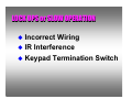
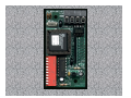
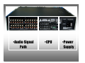
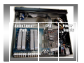
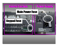
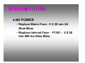
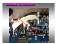
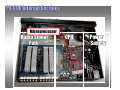
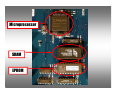
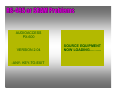
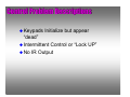
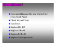
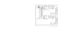
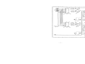
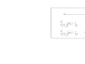
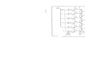
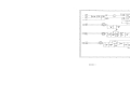
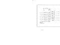
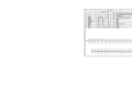
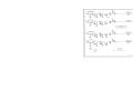
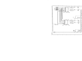
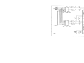
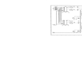
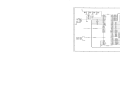
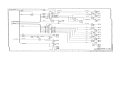
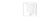
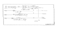
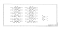
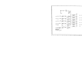
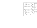
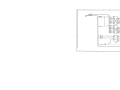
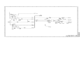
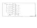
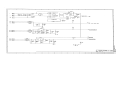
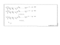
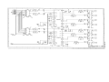
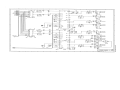
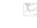
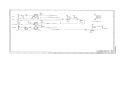
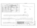
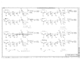
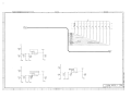
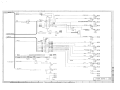
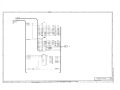
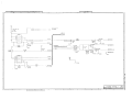
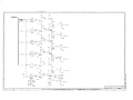
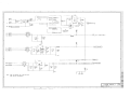
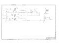
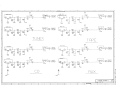
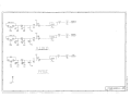
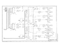
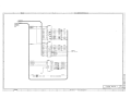
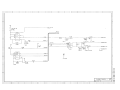
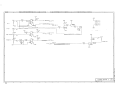
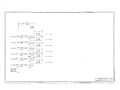
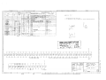
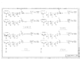
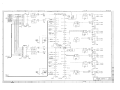
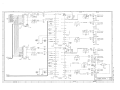
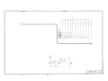
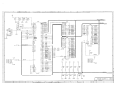
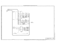
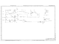
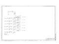
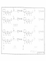
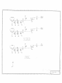
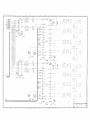
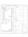
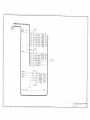
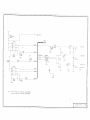
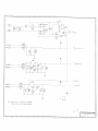
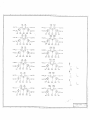
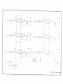
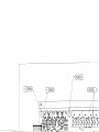
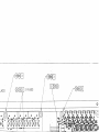
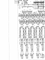
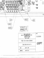
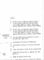
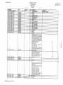
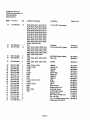
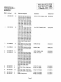
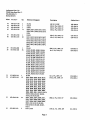
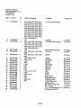
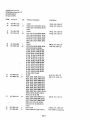
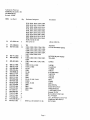
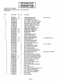
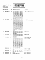
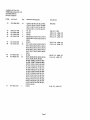
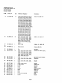
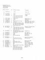
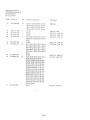
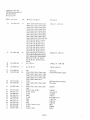
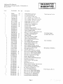
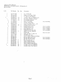
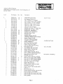
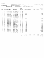
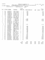
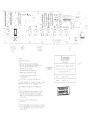
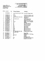
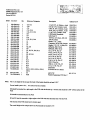
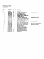
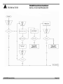
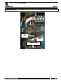
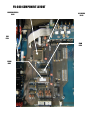
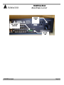
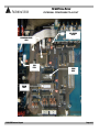
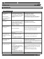
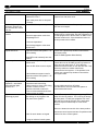
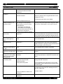
AUDIOACCESS PX-600 MULTI-ROOM PREAM/CONTROLLER PRELIMINARY SERVICE MANUAL Harman Consumer Group 250 Crossways Park Dr. Woodbury, New York 11797 FEATURES Six Zone, Multi-Room, Multi-Source Audio System Flagship of the Audioaccess product line, the PX-600 Multi-Room Preamp/Controller forms the heart of a powerful multiroom audio system. Together with our time proven wall-mounted keypads and conventional audio source equipment, the PX-600 allows you to access and control five different music sources in six different areas simultaneously. The PX-600 combines a learning IR based source controller with six independent stereo preamps to form a six zone system in one compact package. Multiple PX-600s are easily interconnected to form systems as large as 36 independent zones and the PX-600 can be readily interfaced to both complex home automation and home theater systems. You can turn zones on or off, select sources, control their basic functions, and change volume independently in each zone, by just the touch of a single button on the KPS keypad. And unlike rotary volume controls, our low profile keypad blends seamlessly with any decor. The PX-600 can also be operated from its own optional handheld IR remote control from any zone. Of course, the main zone can always be operated from the PX-600's front panel. Learning to operate the system is simplicity itself. Keypads, remotes, and even the front panel have identical controls and operate in exactly the same way. Customized System Operation The PX-600 is configured at the time of installation via a detachable handheld programmer that is available only to authorized dealers, preventing casual tampering with the comprehensive system programming. Programmable features include: turn-on volume, maximum volume, lockout, bass and treble settings for each zone, group setup, paging setup, and specific IR protocols for tuners, CD players, high-capacity CD changers, tape players and VCRs, as well as special macro commands tailored for control of popular surround processors. Optional modules provide door chime and paging capability and an RS-232 interface for integrating the PX-600 with computer-based home automation systems. The PX-600 is complemented both functionally and aesthetically by a Multi-Room Expander and a Multi-Room Amplifier. This combination forms a solution for all of your multi-room needs. Features • • • • • • • • • • • • • • • • • • • • • • • • Simple, intuitive operation Easy installation and programming External keypad termination board for easy hookup in advance Each zone has independent access to each of five audio inputs plus a paging input Infrared receiver built into each keypad Main zone rear panel IR input, compatible with standard IR repeaters Four-conductor wiring to keypads (two twisted pairs: telephone or data cable) External fuse protects keypad (mis) wiring Main zone operable via front panel – in addition to keypad Keypads control basic functions of audio sources via learned infrared commands External plug-in programmer (required for setup) Each zone assignable to one of three ALL ON groups (or none) Zone setup and infrared commands are stored in non-volatile memory Compatible with the Audioaccess six-zone, stereo, multi-room amplifier Compatible with the Audioaccess multi-room expander Expandable to 36 zones Paging and doorbell features available with optional Page/Doorbell Module RS-232 Interface Module available Compatible with other popular home automation and control systems Special grounding, filtering and intelligent circuit design for superior protection IR outputs compatible with industry standard systems Trigger outputs designed to drive relays for each zone System trigger output active whenever any zone is on IR loopthru output Specifications PX-600 Multi-Room Controller Audio Section Inputs: • • • Five stereo source inputs, 1 mono page input, each with loopthru capability Input impedance: 10k ohms Maximum input voltage: 3.5 Vrms Outputs: • • Six stereo preamp outputs with independent volume, bass and treble Six stereo zone outputs (fix level post input selector) • Tape output from the main zone (zone 6) Source Equipment Control and Interface Inputs: • • • • Trigger input to facilitate sharing source equipment (controls switched outlet and "stop" commands) Keypad interface connector DC voltage input for zone trigger outputs Hardwired IR input to control main zone from industry standard IR receivers Outputs: • • • • • Trigger output from each zone to control external relays One system trigger output to control external relay (active when system is on) Six infrared emitter jacks, one for each audio source (5) plus ALL IR loopthru output Switched AC outlet (North American model only) Controls: • • • • • • Front panel controls zone 6 (controls: power, source selectors, volume, mute, and All Off) Independent source selection: Tuner, CD, Tape, Aux, Video, etc. Control of basic source functions (i.e. play, skip track, skip disc, skip preset, fast forward, etc.) Independent volume control per zone Independent On/Off per zone Programmable All On features Specifications Preamp Outputs Zone Outputs Frequency Response 10-84kHz, +0, -1 dB 10-95kHz, +0, -1 dB S/N (ref: 1kHz, 1 Vrms, Filter at 22kHz, Volume at unity gain > 99 dBV > dBV THD+Noise (@ 1kHz, Filter at 80kHz, Volume set at unity gain <0.008% (500mV input signal) <0.004% (1Vinput signal) Maximum Output Level 3.5 Vrms 3.5 Vrms Output Impedance 470 ohms 470 ohms Left/Right Crosstalk (@1kHz, <-85 dB each input) <-85 dB Input to Input Crosstalk (@ 1kHz, any two inputs <-100 dB <-100 dB Zone to Zone Crosstalk (@ 1kHz, any two zones <-100 dB <-100 dB Maximum Gain 20 dB Unity Volume Control 80 dB in 2 dB steps N/A Bass (Shelving type, 100 Hz) +15, -12 dB (3 dB steps) N/A Treble (Shelving type, 10kHz) +12, -12 dB (3 dB steps) N/A Signal Connector Type RCA with short hot pin (makes shield connection first) Power Requirements: • 115 volts AC, 50Hz, 40 watts (not including equipment connected to switched outlet) Dimensions/Weight: • • 17-3/8" W x 4" H x 15" D (442mm x 102mm x 381mm) (with connectors & feet) 12.2 lb (5.5 kg) PX-600 Field Repair LOCK UPS or SLOW OPERATION Incorrect Wiring IR Interference Keypad Termination Switch KEYPAD INSTALLATION Make Tight Connections Insure Power, Ground, and Data wires are in Correct Order Provide Strain Relief On KPT Keep On hand Extra KPT Blocks Do Not “Insert” Insulation Into Connector Install Keypad with Termination Switch in “UP” Position (off) KEYPAD REPAIRS Replace RS 485 Driver Replace Keypad Processor Board Replacing Processor Board Audioaccess MCI MCI Multi-room Computer Interface RS-232 to RS-485 Translator PX-600 Field Repairs Unit Contains 3 Sections – Audio Preamplifiers – CPU – Power Supply Field Repairs May be Performed to Power Supply and CPU •Audio Signal Path •CPU •Power Supply Audio Signal Path CPU Power Supply Control Section Power Supply Main Power Fuse Keypad Fuse Internal Fuse POWER SUPPLY FIXES NO POWER – Replace Mains Fuse - 5 X 20 mm 2A Slow Blow – Replace Internal Fuse - F1301 - 5 X 20 mm 500 ma Slow Blow Main Power Issues Check Power Load on Convenience Outlet – Do not power amps directly with PX-600 – Do not Exceed 200 Watts on PX-600 outlet AC Line condition +- 10% rated Voltage Use Un-switched Outlets for ALL Audioaccess Components PX-600 Powers UP but Cycles Power on and OFF? Unit Hard Power Up AUDIOACCESS PX-600 VERSION 2.04 -ANY- KEY-TO-EXIT• “ALL OFF ” LED on PX 600 Cycling On and Off Replacing RS-485 Driver RS485 TVS Bus Protectors RS-485 Driver PX-600 Internal Sections Microprocessor Audio Signal Path CPU Power Supply UNIT CYCLES ON AND OFF REPLACE Replace RS-485 Driver Microprocessor Microprocessor SRAM EPROM RS-485 or SRAM Problems AUDIOACCESS PX-600 VERSION 2.04 -ANY- KEY-TO-EXIT- SOURCE EQUIPMENT NOW LOADING………. Control Problem Descriptions Keypads Initialize but appear “dead” Intermittent Control or “Lock UP” No IR Output Control Repairs Disconnect Keypad Bus and Check Unit From Front Panel Check Keypad Fuse Data Reset Replace RS 485 Replace SRAM Replace EPROM Replace Microprocessor PX-600 SCHEMATICS CONTENTS MAIN BOARD REV B0 MAIN BOARD REV B1 MAIN BOARD REV C0 MAIN BOARD REV C1 MAIN BOARD REV D0 MAIN BOARD REV D1 MAIN BOARD REV D2 FRONT PANEL REV C0 PROGRAMMER REV B0 PX-600 Field Repair Guide Version xxxx Rev Level xxx PX-600 FIELD REPAIR FLOW CHART INITIAL SYSTEM POWER-UP PX-600FRK Power Up Flow Page 1 of 1 PX-600 FIELD REPAIR FLOW CHART KPS BUS OPERATIONS PX-600FRK KPS Bus Flow Page 1 of 1 PX-600 FIELD REPAIR TROUBLE SHOOTING OCTOBER 8, 2003 # XXXXXX] PX-600 REPAIR PARTS LOCATIONS Power Fuse F1301 RS485 Driver U1106 Microprocessor U801 SRAM U804 EPROM U803 Front of PX-600 PX-600 Field Repair Trouble Shooting.doc Page 4 Madrigal Audio Laboratories P.O. Box 781 Middletown, CT 06457-0781 (860) 346-0896 FAX (860) 347-6251 TECHNICAL SERVICES AUDIOACCESS PX-600FRK – PX-600 FIELD REPAIR KIT SEPTEMBER 22, 1999 The Audioaccess Field Repair Kit has been developed for authorized Audioaccess installation companies to improve servicing time and overall customer satisfaction of PX-600 systems. Field repair eliminates system downtime and the cost of multiple trips to job sites to reinstall keypads and controllers. This kit contains socket parts and subassemblies to perform simple repairs to Audioaccess KPS keypads and PX-600 controllers. We recommend that dealers bring this kit on all Audioaccess installation and/or troubleshooting visits. The following parts and quantities are included in each kit. Dealer costs are also included for reordering individual components: DESCRIPTION Part NO. LOCATION 705-1000-800 664-2101-200 664-1001-500 380-00160-00 380-00050-00 605-0485-008 450-9862-100 926-0600-002-00 606-8055-000 606-1244-000 610-1204-000 PX-600 PROG MAINS FUSE KEYPAD (NEW) KEYPAD F 1301 (INTERNAL) U 1106 KPS FRONT PANEL U 801 U 804 U 803 Qty DLR DLR EXT EACH PX-600/KPS PARTS Ribbon Cable for Programmer Fuse 2 Slo Blo Fuse 1.5 5 X 20 mm Fuse 1.6 Slo Blo Fuse 500ma Slo Blo LTC485 Bus Driver Keypad Processor Board Volume Control ass’y Microprocessor SRAM V2.04 Total Cost if purchased separately. Total Kit Price PX600FRK 1 6 6 6 6 12 4 1 1 2 2 $10.50 $0.93 $1.47 $0.78 $0.69 $3.45 $38.82 $60.50 $26.82 $31.95 $20.00 $10.50 $5.58 $8.82 $4.68 $4.14 $41.40 $155.28 $60.50 $26.82 $63.90 $40.00 $426.62 $245.00 Please contact Audioaccess Technical Support at 888-691-4171 or 860-346-0896 from the job site when a specific Audioaccess system malfunction occurs. Audioaccess will assist the installer in system diagnostics and possible onsite repair. Below is a brief description of usage for some of the parts listed above. 1. LTC 485 Bus Driver – This eight-pin IC sends and receives communication data on the RS-485 keypad bus. This device is located in each KPS keypad, PX-600, PX-603, and MRX-NT. The RS-485 transceiver is socket mounted in KPS keypads manufactured after April 1, 1998 and in the PX-600 dating from 1995. 2. SRAM – This component provides the non-volatile memory in the PX-600. The SRAM “holds” all programmed settings in a system. This is the second part to suspect after replacement of the LTC 485 driver for any functional or source control related failure. 3. EPROM – This is the operating software for the PX-600. Version 2.04 is the current software version. 4. Microprocessor – The main “brain” of the system. This part may need replacement if RS-485, EPROM and SRAM replacements result in continued system control errors. 5. Keypad Processor Board – A failed keypad may require the replacement of the entire keypad processor board. Replacement of this board will result in the successful repair of 99% of remaining keypad related problems. Note - KPS keypads mis-installed or damaged by EMI (Electro-Magnetic Interference) are not covered under the Audioaccess warranty. 6. Volume Control Assembly – This volume control pot on the PX-600 and MRX controls the volume of Zone 6 in these systems. A broken volume assembly will cause the system to “lock up” when zone 6 is “turned on” inhibiting volume and source control in an entire system. PX-600 Field Repair Kit.doc Doc # AA92299 Audioaccess 250 Crossways Park Drive Woodbury, NY 11797 (888) 691-4171 FAX (516) 682-3528 TECHNICAL SERVICES INFORMATION SHEET PX 600 ALL IR Output / MRX Blaster IR Output DECEMBER 8, 1999 (ORIGNINALLY TECHNICAL MEMO 9711) Page 1 of 1 OVERVIEW The “All” and “Blaster” IR Output ports the on the PX-600 and MRX-NT may be used as an alternative or in conjunction with the individual source IR control ports (ie: CD Tape AUX and Video) to control source components in an Audioaccess system. As suggested by its name, these “all” output ports route all of the IR codes that are learned by the PX 600 and MRX-NT. The dedicated IR outputs route only IR for a specific source. Output voltages may be adjusted on both the PX-600 and MRX-NT for blaster or emitter settings. The following are some suggestions of how these “ALL” outputs are used. CONFIGURATION OF THE ALL IR OUTPUT PX-600 - The All Output is factory configured for standard low power emitters but can be changed to drive a blaster style emitter. To make this change, remove the top cover, and move the header jumper located on the main board at P120, one position back towards the rear panel. The two positions are labeled Blaster and Emitter. MRX-NT - The ALL output of the MRX-NT is factory set for using high power blaster emitters. Functionally, the IR output is identical to that of the PX-600. To modify this to a standard low power emitter port you must modify the emitter being used. Using the positive supply wire, place a one 1K Ohm 1/4w 5% resistor in series with the LED. This will cause a voltage drop across the resistor and will avoid damaging the emitter’s LED. USING THE ALL IR OUTPUT Application 1 – If using source components from a single manufacturer that contain control in/out ports, you may use only the “ALL” out (emitter setting) and daisy chain the control signal to each of the source components. This method eliminates the emitters on the front panel of the source gear and is easy to install. The source gear must be opto-isolated. Opto-isolation indicates that the source component internally strips the IR carrier from the control signal. If this is not the case, you may use the Xantech 794 and 797 series of interface modules for direct connection between the PX-600 IR out and the source component’s control inputs. Using the “ALL” output is not desirable if you wish to control two identical source components that use the same IR codes. In this case it is better to use the dedicated IR ports that allow for independent control of identical sources. Application 2 - Four additional source control functions are located in the video programming and may be accessed using the Audioaccess RT-A remote. These extra control functions may be used by any source component if you use the “ALL” control port to expand functionality of a given source. For example, in for a high capacity CD changer, you may use the macro functions located in the HIGH CAPACITY CD Programming, and also add extra transport functions located in the “Video” programming under Channel UP, Channel DN, Fast Forward, and Rewind. Instead of connecting an IR emitter from the CD output, connect it to the “ALL” Output port. These extra functions will then be available to the CD changer only when using the Audioaccess RT-A remote. Only one source may use these additional functions. Application 3 – The Zone 6 Macro incorporates a 10 step Video Enter Macro, 10 step Video Exit Macro, and Volume Up and Down commands for controlling an external AV processor or receiver. The “All” or “Blaster” output must be used to route the IR commands to the theater components. In some cases it may be necessary to include a secondary IR repeater system connecting block which allows for multiple output connections to the various components that need to receive IR control data. Alternatively, a Blaster style emitter may be used to “spray” the room with the appropriate commands when this setting is selected. Note – For any questions concerning the use of the “ALL” IR output, please contact our Technical Support Department at 888-691-4171. PX-600 All IR Output.doc DOC# AA092603 Page 1 WB-TS / FB-CR October 8, 2003 No00 Madrigal Audio Laboratories, Inc. We define products for your ears, eyes, and mind. 2081 South Main Street Middletown, CT 06457.07081 www.madrigal.com Phone: 860.346.0896 Fax: 860.346.1540 PX-600 LEARNING PARASOUND IR PAGE 1 OF 1 OVERVIEW The IR bursts on Parasound remotes are short quick bursts. If the button on the Parasound remote is held too long the px-600 programmer will lock up. To avoid this from happening the button on the remote must be pressed and released quickly and then the volume up button press to fill up the IR. space inside the PX-600. LEARNING IR. CODES 1. Hold the remote in front of the IR. window on the programmer. 2. Press and release the button for the command being learned. 3. Press the VOLUME UP button and hold until programmer says STORAGE SUCCESSFUL. NOTE : For the volume up or down commands this step should be skipped. 4. Repeat the previous steps until all buttons IR. commands are learned PX-600 Parasound IR Learning.doc Voltage Change for PX-600 Directions to change from 120VAC to 230VAC version. Locate the terminations for the power transformer to main PCB. Looking from the back of the unit they are directly above of the AC power connection and main switch. The Common must be connected always. The 2 transformer wires that are presently connected to US-Only ( Brown = P17 & Black/White = P18)should be moved and re-connected to the NON-US terminal block ( Brown = P22 & Black/White = P23) while maintaining the same color code for this connection as it was for the US-Only version. The main power fuse value must be halved for 230V. Values as follows 120V= 2amp slo blo @ 250 volt. 230V= 1amp slo blo @ 250 volt Non-US - 230V P22 Brown P23 Blk/Wht Common P16 Brn/Wh P19 Blk US Only - 120V P17 Brown P18 Blk/Wht If you have any questions regarding this change, please call our Technical Support Department at (510) 293-0183 Audioaccess TECHNICAL MEMO by madrigal audio labs 2081 S. Main St, Middletown, CT 06457 Ph: 888-691-4171, 860-346-0896... Fx: 860-346-1540... PX-600 EPROM CHANGE CAUTION - Be sure to ground yourself before performing this procedure!! This is a static sensitive device. To change the EPROM in a PX-600 - Make sure to follow the ESD Warning on the page 1, provided. Take off the top cover and look for U803 on the main circuit board. With an IC puller or a small screwdriver, very carefully remove the old EPROM. Replace the new EPROM in the same location and make sure that notch in the IC is facing the same direction as the old one. You can also verify this by the drawing on the PCB. Replace the top cover with the same screws in the proper locations. Hook up the programmer and power up the PX-600. Go into the TEST MENU and scroll to DATA RESET, then press ENTER. This will clear the memory of all IR codes and reset the controller to factory default settings. You are now ready to configure the system to your client’s needs. After you finish programming, check each zone for proper operation. If there are any questions please contact the customer support department at one of the numbers above. Madrigal Audio Laboratories P.O. Box 781 Middletown, CT 06457-0781 (860) 346-0896 FAX (860) 347-6251 TECHNICAL SERVICES INFORMATION SHEET PX-600 SRAM REPLACEMENT DECEMBER 8, 1999 Page 1 of 2 OVERVIEW This procedure will guide you through the steps needed to replace the SRAM in the PX-600. Read the procedure carefully before beginning the SRAM replacement. INSTALLING THE SRAM WARNING: Follow Anti-static Procedures! A static-free workspace with conductive mat and wrist-strap or equivalent precautions must be used to protect static sensitive parts on the control board from damage. Before touching any of the boards inside the MRX, if you're not using the mat and wriststrap, discharge any static you may be carrying by touching something metal, preferably something that is grounded like the wallplate screw on a grounded electrical box. You should re-ground yourself often throughout the procedure and certainly whenever you are about to handle a board, or when you have walked away momentarily and come back. What is Needed Philips Screwdriver Procedure 1. Turn OFF the PX-600 main power on the rear panel and disconnect the AC cord. 2. Remove the top cover of the PX-600. 3. Carefully remove the IC at location U804. This is next to the EPROM (Vx.xx). It can be found on the mid left side of the printed circuit board when looking downward from the front of the unit. Note that the correct SRAM should be Benchmarq BQ 4011. If a Benchmarq BQ 4010 is installed in this location, it should be replaced with the BQ 4011. 4. With the FRONT of the PX-600 towards you, Carefully place the new SRAM into the socket with the dimple on top of the IC in the upper right hand corner and give a slight push down to ensure the SRAM is properly seated in the socket. There is a dimple on the IC designating pin 1 as well as a notch designating the front end of the IC. The notch is also visible on the IC socket and on the PCB silk-screen. And give a slight push down to ensure the SRAM is properly seated in the socket. 5. Replace the top cover with the original screws. 6. Hook up the programmer and power up the PX-600 from the main power switch on the back panel. 7. Go to the main programming menu and choose TEST MENU, scroll to DATA RESET and press ENTER. 8. This will clear the memory of all IR codes and reset the controller to factory default settings. 9. You are now ready to configure the system to your client’s needs. After you have finished programming, check each zone for correct operation. If you have questions please contact our Customer Support Department at the above numbers. PX-600 SRAM Replacement.doc DOC# AA12899 Page 1 WB-DW / FB-DW TECHNICAL SERVICES INFORMATION SHEET DECEMBER 8, 1999 Page 2 of 2 SRAM LOCATION The SRAM can be found at location U304. Please see diagram below showing location on the PCB. SRAM EPROM Front of PX-600 PX-600 SRAM Replacement.doc Page 2 PX-600 COMPONENT LAYOUT MICROPROCESSOR U801 485 DRIVER U1106 FUSE F1301 SRAM U804 EPROM U803 PX-600 FIELD REPAIR REAR PANEL LAYOUT AC MAINS FUSE KPS / 485 BUS CONNECTOR KPS / BUS FUSE PX-600FRK Rear Layout Page 1 of 1 PX-600 FIELD REPAIR INTERNAL COMPONENT LAYOUT 485 DRIVER U1106 MICROPROCESSOR U801 FUSE F1301 SRAM U804 EPROM U803 PX-600FRK Internal Layout Page 1 of 1 Madrigal Audio Laboratories P.O. Box 781 Middletown, CT 06457-0781 (860) 346-0896 FAX (860) 347-6251 Technical Services Information Sheet DSS PROGRAMMING JULY 17, 1997 Page 1 of 2 OVERVIEW There are two possibilities for programming the DSS in a PX-600 system, using your choice of source inputs. Each method has its pros and cons, but one of them should work for your particular client’s needs. Follow the examples below to program a DSS to suit the customers needs. SAMPLE # 1: (SEE FIGURE 1, HIGH-CAPACITY CD OPTION) Caution: using this method will take away the option of having a High-capacity CD player in the system with group control. Additionally, the response time between changing channels tends to run a little slower. The advantage to using this method is that you do not have to use any of the DSS program features, leaving them open for their intended use. To start the programming 1) 2) 3) 4) 5) 6) 7) Go to LEARN IR. Go to CD Go to OTHER HIGH CAP (If the unit does have discrete IR power, you must first go to LOW CAP and enter a power command). Follow the steps outlined below to program your presets (groups), up to six. The STOP command is not used. Leave this address in memory empty. At SKIP TRACK, enter the DSS code for “channel up”. Enter the number of presets (groups), up to 6. This sample is based on a total of 30 stations, with presets set at 5 station increments. The “delay” command is optional, as this will add a .7 second delay between commands if necessary to run the macro correctly. It depends on your particular unit. You may want to try it without the delay first. If there is more than one group, make sure GROUP 1 is the same as the “PLAY” macro .The first press and hold will go to GROUP 2. Figure #1 #1 HIGH CAP CD SAMPLE PROGRAMMING TABLE FOR Sony DSS PX-600 DISPLAY DSS IR REMOTE BUTTON INPUT IR FOR PLAY STEP 1 5 INPUT IR FOR PLAY STEP 2 DELAY INPUT IR FOR PLAY STEP 3 INPUT IR FOR PLAY STEP 4 INPUT IR FOR PLAY STEP 5 INPUT IR FOR PLAY STEP 6 INPUT IR FOR STOP INPUT IR FOR SKIP TRACK NUMBER OF GROUPS # INPUT IR FOR GROUP 1 STEP 1 INPUT IR FOR GROUP 1 STEP 2 INPUT IR FOR GROUP 1 STEP 3 0 DELAY 0 ENTER (OPTIONAL) NOT USED CHANNEL UP 6 5 (FIRST DIGIT OF DESIRED STATION) DELAY 0 (SECOND DIGIT OF DESIRED STATION) DELAY 0 (THIRD DIGIT OF DESIRED STATION) ENTER (OPTIONAL) 5 (FIRST DIGIT OF DESIRED STATION DELAY 0 (SECOND DIGIT OF DESIRED STATION) DELAY 5(THIRD DIGIT OF DESIRED STATION) ENTER (OPTIONAL) INPUT IR FOR GROUP 1 INPUT IR FOR GROUP 1 INPUT IR FOR GROUP 1 INPUT IR FOR GROUP 2 INPUT IR FOR GROUP 2 INPUT IR FOR GROUP 2 STEP 4 STEP 5 STEP 6 STEP 1 STEP 2 STEP 3 INPUT IR FOR GROUP 2 STEP 4 INPUT IR FOR GROUP 2 STEP 5 INPUT IR FOR GROUP 2 STEP 6 DSS Programming DOC# AA91797 Page 1 WB-TS / FB-DW TECHNICAL SERVICES INFORMATION SHEET DSS PROGRAMMING Page 2 of 2 SEPTEMBER 29, 1999 This process will continue until the programming is complete for the number of presets you have selected. Your client may want a specific station attached to press and hold function. All the stations are determined by your programming. After the last GROUP is entered, the programming display shows the source selection screen for LEARN IR. From there you may program IR commands for other sources or press STORE/ENTER twice to exit programming mode. SAMPLE # 2: (SEE FIGURES 2A/2B ) The second method uses the “Custom Guide” of the DSS to program desired stations, and the PX-600 to control it. However, you take away the “Custom Guide” from the client in the following manner. A. The “channel up/down” buttons will only scan the stations contained in the “Custom Guide”. B. Your client will need to use the other “Guides” available to change channels on the DSS during regular DSS viewing. The advantage to this method is the ability to program as many stations as are available on the Custom Guide. LOW CAP CD, AUX, TAPE, or VIDEO can be used on the PX-600 to control the DSS. We’ve included samples from TAPE or CD under AUX programming.. Again, a POWER command is necessary if the unit does have discrete IR power, if you wish to have the source turn on and off with the system. Figure #2A (TAPE) SAMPLE PROGRAMMING TABLE FOR Sony DSS PX-600 DISPLAY DSS IR REMOTE BUTTON NUMBER OF TAPES INPUT IR FOR PLAY INPUT IR FOR STOP INPUT IR FOR FORWARD PLAY INPUT IR FOR REVERSE PLAY TAPE !A TAPE 1B 1 CHANNEL UP /CUSTOM GUIDE NOT USED CHANNEL UP CHANNEL UP CHANNEL DOWN NOT USED Figure #2B (CD) SAMPLE PROGRAMMING TABLE FOR Sony DSS PX-600 DISPLAY DSS IR REMOTE BUTTON NUMBER OF DISCS INPUT IR FOR PLAY INPUT IR FOR STOP INPUT IR FOR SKIP TRACK DISC 1A DISC 1B DSS Programming 1 CHANNEL UP/CUSTOM GUIDE NOT USED CHANNEL UP CHANNEL DOWN NOT USED Page 2 TECH NOTES IR PROGRAMMING Ideal Programming Conditions In order to minimize interference and maximize the reliability of source control, follow these guidelines during programming: 1. Eliminate direct or bright indirect sunlight near the PX-600 Programmer. 2. Turn off any halogen, fluorescent and neon lights in the area. 3. Position Programmer so that no lights, even incandescent lights, shine directly into the IR input window. 4. Hold the transmitter for the source equipment you are programming 2” to 6” from the PX-600 Programmer. Hold it level and squarely aligned with the red IR input window. 5. Except as directed elsewhere in these Tech Notes, when you enter a command into the PX-600 Programmer, press and hold the button on the IR remote until you see the words: “Storage Successful” on the LCD screen. CD - Multiple Skip Track You may encounter some CD players that skip more than one track when you issue the SKIP TRACK by pressing the CD button the second and subsequent times. These players probably utilize 32 bit IR codes. When learning these 32 bit codes, the PX-600 will take 2-3 seconds before indicating “Storage Successful”, whereas 16 bit codes are stored almost immediately. When 32-bit codes are learned and played back, often the player sees two separate commands and thus skips more than one track. To compensate for this and skip only one track, get into programming and proceed to the spot where you are to enter the SKIP TRACK command. Briefly tap SKIP TRACK on the CD’s remote and immediately press and hold another button on the remote until the PX-600 indicates “Storage Successful” on the display. The PLAY button works well for this unless the player has a combination PLAY/PAUSE button. If this is the case, or if the player is affected in some other way when you press PLAY while it is already in PLAY, use a command from a remote that has nothing to do with the audio system to complete the storage of that IR address. The point is to fill the space allotted for the command without duplicating the SKIP TRACK command. 42 System Learning Remotes These remotes are designed to control the functions of a stack of same-brand equipment, as well as learn the IR commands of other equipment. Often the PLAY buttons on these remotes send two IR commands: one to the receiver to select the input, and one to the player (CD, Tape, etc.) to start it playing. When using this type of remote to program IR commands into the PX-600, the PLAY command often gets cut off and is not stored properly. When this happens it will appear that the PX-600 cannot control the source equipment. For this reason, it is best to use the transmitter for the player itself whenever possible. However, sometimes the individual player's remote is not available or doesn't exist. To program the PLAY command or any other command using a System Remote, follow this procedure: Place the remote in the proper location for programming. 1. Place your hand between the remote and the PX-600 Programmer. 2. Press PLAY - your hand will block the first command (SOURCE SELECTION). 3. Move your hand in time to record the second command (PLAY). This may take only a fraction of a 4. second. It may take a little practice to get the timing right, but it works and it may get you out of a jam. IR Programming tips for Tape Players There are different formats for the control of tape players, and clients have differing needs or expectations of how a player should respond from a keypad or remote. With this in mind, we have outlined the programming protocol for the TAPE input along with some suggested ways of using it. During IR programming for TAPE, enter the number of tapes the player has and the commands for: PLAY, STOP, REVERSE PLAY and FORWARD PLAY, then TAPE 1A/1B, TAPE 2A/2B, etc. The PX-600 issues PLAY the first time TAPE is selected in a zone, unless it was already selected in another zone. STOP is issued shortly after the first zone is turned on in the system, after the last zone is turned off and whenever the user switches out of TAPE, unless another zone has TAPE selected. The REVERSE PLAY and FORWARD PLAY commands toggle back and forth each time you press TAPE after the first time. Normally these provide a CHANGE DIRECTION function on players that have two PLAY buttons. TAPE 1A/1B, 2A/2B, etc. are two-step commands issued when you press and hold the TAPE button. The intended use of the two steps is to accommodate multi-tape changers that require a tape select command followed by the tape number or the tape number followed by PLAY. Most players change tapes by pressing the tape number only, in which case enter the tape number in the “A” step and skip the “B” step. If you have a tape player with one PLAY button and a DIRECTION button: 1. Enter DIRECTION for both the REVERSE PLAY and FORWARD PLAY commands so that you get the DIRECTION function each time you press TAPE after the first time. Using this option, you could tell the PX-600 you have 2 tapes and enter FF into TAPE 1A, press STORE to skip TAPE 1B, then enter PLAY into TAPE 2A and press STORE to skip TAPE 2B. You'll now be able to toggle between FF and PLAY on the press-and-hold function. 2. Enter FF into REVERSE PLAY and PLAY into FORWARD PLAY, then enter DIRECTION in TAPE 1A. This toggles between FF and PLAY to find a particular part of a tape. When you press and hold TAPE, you change the direction of play. Another twist to this is to tell the PX-600 that the player has 2 tapes as in Option 1, and enter REW and PLAY in TAPE 1A and TAPE 2A. Then you toggle between FF and PLAY by momentarily pressing TAPE and toggle between REW and PLAY using the TAPE press-and-hold function. 43 Sources with IR input on back panel Many sources, particularly tape decks and tuners, have no IR input to the front panel. These products are designed for use with receivers and a “system” remote. Some tape players and other source components have opto-isolated IR inputs as with Harman Kardon equipment. With these components, plug the emitter outputs of the PX-600 directly into the IR inputs on the back panels using mono mini plug to mini plug cables. When the IR inputs are not opto-isolated, route the IR through a CD player in the system that is the same brand and series, and connect the CD player via the IR port to the back of the tape deck. Use the ALL OUTPUT in this case. If this is not an option consider using a Xantec 794/797 connecting block and route the IR signal through this device which provides opto-isolation for the source component. Using a CD Player on the Tape input The programming is the same for PLAY, STOP and SKIP DISC (SKIP TAPE). However, enter SKIP TRACK for both REVERSE PLAY and FORWARD PLAY. Then each time you press TAPE on the transmitter, keypad or front panel, you will get SKIP TRACK on the CD Player. Laser Video Disc Players as main CD Players Many current LD players play regular CDs as well as laserdiscs. One may be tempted to use these players as both the CD and VIDEO source. We recommend a separate, dedicated CD player on the CD input. However, if you must use the LD/CD arrangement, please consider the following: Split the audio output into both the CD input and the VIDEO input of the PX-600. If you're using some other means of video switching, connect one of the splits into that device and then into the PX-600. In this way the audio will track with the labeling on the keypad. LD players often have PLAY/PAUSE buttons which means you will undoubtedly get PAUSE at some point when you really want PLAY. LD players often have STOP and EJECT on the same button, so it is likely that the drawer will open when you don't want it to. You may opt to eliminate the STOP command altogether. If you plug the LD player into the PX-600 for AC power, it may power up into a “standby” mode. Before it accepts any other commands, the player needs the IR POWER command. Use the POWER command from either the CD or the VIDEO input - not both. You can get around this on some players by setting the timer to the “on” position if it has this feature (this solution may work for any equipment with stand-by power). Sharing Sources with Other Systems Some pre-amps, receivers and A/V surround receivers short their audio inputs together when they are turned off. This will show up in the PX-600 as cross talk between CD, TAPE, AUX and VIDEO if the PX-600 is on and the other system is off. This cross talk or bleed from one source to another is often accompanied by low frequency distortion. One solution is a line level switch made by Sonance, Model AL-1S, which has A/B switching between multiple sources and provides the necessary isolation. It requires a 12VDC power supply, also available from Sonance, and is reported to work perfectly in this situation. The only other way to deal with it is to build a relay circuit that isolates the preamp or receiver from the source equipment when it is off. 44 AUDIOACCESS Madrigal Audio Laboratories P.O. Box 781 Middletown, CT 06457-0781 (860) 346-0896 FAX (860) 347-6251 TECHNICAL SERVICES PX-600FRK – PX-600 FIELD REPAIR KIT SEPTEMBER 22, 1999 The Audioaccess Field Repair Kit has been developed for authorized Audioaccess installation companies to improve servicing time and overall customer satisfaction of PX-600 systems. Field repair eliminates system downtime and the cost of multiple trips to job sites to reinstall keypads and controllers. This kit contains socket parts and subassemblies to perform simple repairs to Audioaccess KPS keypads and PX-600 controllers. We recommend that dealers bring this kit on all Audioaccess installation and/or troubleshooting visits. The following parts and quantities are included in each kit. Dealer costs are also included for reordering individual components: DESCRIPTION Part NO. LOCATION 705-1000-800 664-2101-200 664-1001-500 380-00160-00 380-00050-00 605-0485-008 450-9862-100 926-0600-002-00 606-8055-000 606-1244-000 610-1204-000 PX-600 PROG MAINS FUSE KEYPAD (NEW) KEYPAD F 1301 (INTERNAL) U 1106 KPS FRONT PANEL U 801 U 804 U 803 Qty DLR DLR EXT EACH PX-600/KPS PARTS Ribbon Cable for Programmer Fuse 2 Slo Blo Fuse 1.5 5 X 20 mm Fuse 1.6 Slo Blo Fuse 500ma Slo Blo LTC485 Bus Driver Keypad Processor Board Volume Control ass’y Microprocessor SRAM V2.04 Total Cost if purchased separately. Total Kit Price PX600FRK 1 6 6 6 6 12 4 1 1 2 2 $10.50 $0.93 $1.47 $0.78 $0.69 $3.45 $38.82 $60.50 $26.82 $31.95 $20.00 $10.50 $5.58 $8.82 $4.68 $4.14 $41.40 $155.28 $60.50 $26.82 $63.90 $40.00 $426.62 $245.00 Please contact Audioaccess Technical Support at 888-691-4171 or 860-346-0896 from the job site when a specific Audioaccess system malfunction occurs. Audioaccess will assist the installer in system diagnostics and possible onsite repair. Below is a brief description of usage for some of the parts listed above. 1. LTC 485 Bus Driver – This eight-pin IC sends and receives communication data on the RS-485 keypad bus. This device is located in each KPS keypad, PX-600, PX-603, and MRX-NT. The RS-485 transceiver is socket mounted in KPS keypads manufactured after April 1, 1998 and in the PX-600 dating from 1995. 2. SRAM – This component provides the non-volatile memory in the PX-600. The SRAM “holds” all programmed settings in a system. This is the second part to suspect after replacement of the LTC 485 driver for any functional or source control related failure. 3. EPROM – This is the operating software for the PX-600. Version 2.04 is the current software version. 4. Microprocessor – The main “brain” of the system. This part may need replacement if RS-485, EPROM and SRAM replacements result in continued system control errors. 5. Keypad Processor Board – A failed keypad may require the replacement of the entire keypad processor board. Replacement of this board will result in the successful repair of 99% of remaining keypad related problems. Note - KPS keypads mis-installed or damaged by EMI (Electro-Magnetic Interference) are not covered under the Audioaccess warranty. 6. Volume Control Assembly – This volume control pot on the PX-600 and MRX controls the volume of Zone 6 in these systems. A broken volume assembly will cause the system to “lock up” when zone 6 is “turned on” inhibiting volume and source control in an entire system. AA92299 - PX-600 Field Repair Kit Doc # AA92299 [logo] [TITLE] [PART NUMBER] OCTOBER 27, 2000 OVERVIEW The PX-600 Field Repair Kit contains components that can be changed in the field to repair the PX-600 system. By following the below flow charts a PX-600 can be diagnosed and repaired at the job site. This will eliminate the need to remove the unit and have the customer down while the unit is being repaired. PARTS INCLUDED DESCRIPTION PART NO. LOCATION QTY DLR EA DLR EXT 705-1000-800 664-2101-200 664-1001-500 380-00160-00 380-00050-00 605-0485-008 450-9862-100 926-0600-002-00 606-8055-000 606-1244-000 610-1204-000 PX-600 PROG MAINS FUSE KEYPAD KEYPAD (NEW) F 1301 (INTERNAL) U 1106 KPS FRONT PANEL U 801 U 804 U 803 1 6 6 6 6 12 4 1 1 2 2 $10.50 $0.93 $1.47 $0.78 $0.69 $3.45 $38.82 $60.50 $26.82 $31.95 $20.00 $10.50 $5.58 $8.82 $4.68 $4.14 $41.40 $155.28 $60.50 $26.82 $63.90 $40.00 PX-600/KPS PARTS Ribbon Cable for Programmer Fuse 2 Slo Blo Fuse 1.5 5 X 20 mm Fuse 1.6 Slo Blo Fuse 500ma Slo Blo LTC485 Bus Driver Keypad Processor Board Volume Control ass’y Microprocessor SRAM Software Eprom v2.04 USING THE PARTS We recommend that any parts used from this kit be replaced to maintain a constant stock within the kit for future service calls. Replacement parts for the kit or new kits can be ordered from Audioaccess with the enclosed parts order form. A list of parts and their quantities are also included. In Warranty Repairs Parts used from this kit for In Warranty repairs will be replaced at no charge provided a serial number for the unit is supplied. When calling Tech Services please have serial number and problem description handy. If the enclosed form is being used please be sure to fill out all the fields on the form or the part will be charged. Out of Warranty Repairs Parts used for Out of Warranty Repairs will be charged. As with In Warranty Repairs please supply serial number of unit when calling. Should you have questions about the use of this kit or need help after all the steps have been followed, please call Audioaccess Technical Services at 888-691-4171. PX-600 Field Repair Guide Page 3 [logo] [TITLE] [PART NUMBER] OCTOBER 27, 2000 TROUBLESHOOTING Basic Troubleshooting Steps Problem Encountered Keypad locked up - lights come on but no functions. System locked up Zone or system locks up after ON button is pressed. Keypad has no functions and no lights Slow reaction time from keypad, front panel or RT-A remote. Find the problem component Unplug (isolate) all keypad wires from control unit and test unit functions from front panel. Test each keypad on system individually. Test using an alternate KPS addressed for the same zone. solution Check all keypad connections. Set DIP switches for correct zone, room, & system. Insure data bus wires polarity. Replace KPS Processor assembly. Check front panel Volume knob is not rubbing on th Motor Pot bracket. Gently pull out knob 1/16 ”. On back panel of head unit. Check bus fuse - Use ohmmeter to measure for 0 ohms. Check bus voltage -Use voltmeter across pin 1 & 4 – DC voltage is unregulated and should be between 8 – 14 volts DC. Check KPS terminator switch. Replace bus fuse w/ 1.5 A slo-blo Check data bus wires polarity. Replace KPS Processor assembly. Check wire terminations. Change to opposite direction and test system speed. Make sure there are no cut or frayed wires and that there are no intermittent shorts in wiring. Disable IR on keypad - DIP switch 9 UP. Keypad turns on but there is Audio in the wrong zone or more than one zone. Keypad turns on but there is Audio in more than one zone. Check for IR interference (Ambient light source) This usually indicates the wrong zone or system address on the KPS keypad - Change wiring to correct amplifier input. Preamp output is connected to the wrong channels on the amplifier. All on group is active. Check PX-600 back panel outputs No Audio in one zone No Audio in any zone PX-600 Field Repair Guide Check DIP switch address settings and make sure the proper zone and system codes are set. Identify Zone What type of Amp is powering this zone? Is it signal sensing turn on/off? Check Speaker continuity. Check Preamp output. Check amp inputs – Check Fuse Source dependent? - Check source input continuity and line level signal. Amplifier ON? Test Zone again but do not issue a press and hold command at turn on from keypad. Variable audio comes out of the preamp section and NOT the zone outputs. All zone outputs become HOT when any zone is active. Turn all zones off but the problem zone. Use the Zone or Room command to find out which zone is active. Is there preamp line level signal. If so, check amp channel. Replace fuse with same value. Fuses. Change source or it’s wiring connection. Insure AC power to Amp. Is not switched unless system is designed to use current amp in this fashion. Page 4 [logo] [TITLE] [PART NUMBER] OCTOBER 27, 2000 Is the amp plugged into a switched outlet that is not on? Audio always very loud in all zones. Sources can be controlled but volume can not. Audio drops out then returns Check main power fuse to Amp and to Preamp. Check PX-600 back panel outputs. What volume level does this occur? Does this happen when music has soft passages in it? Replace fuse with same value. Variable audio comes out of the preamp section and NOT the zone outputs. When using a PX-612 check by slowly adjusting the volume level to a softer point. Use the Zone button on PX-600 programmer or Room button on MRX to see what the actual level is. If the threshold is below 10 the amp needs to be modified. Is it source dependent? Cross talk between inputs and zones. Hum in speakers Does it always happen at the same volume level? Is the Audioaccess system used in conjunction with a local system? – IE: source sharing. Some MRX units inherently have this problem. Is there a cable system integrated with this unit? Check for DC offset at source inputs. Is the Audioaccess system used in conjunction with a local system? – IE: source sharing Popping sound in speakers – associated with switching lights, motors, etc. System or zone turns on seemingly by itself Check terminations for bad connections and loose wiring. Cabling routed too close to AC wiring, dimmers or electric motors. Systems connected to same AC circuit as electromechanical devices causing noises on system. Is there an extra ordinary amount of light shining on any keypad or the front panel of the system? Disconnect the local system – if the problem is not present use a ground loop isolator in line with the local system feed. Install an SMM (Speaker Mute Module) Remove the cable connection. If the problem is not present then use an IN-LINE ground loop isolator or make your own using 2pcs. of 75 to 300 ohm transformers back to back on the 300-ohm side. This effectively makes an isolation transformer. Disconnect the local system – if the problem is not present use a ground loop isolator in line with the local system feed. Terminate wires correctly. Re-rout cables away from AC wiring. Use different AC circuit for either the system or electromechanical device. Disable IR receiver in KPS keypad by putting DIP switch 9 in the UP position. If it is coming in through the front panel – PX-600 use a pigtailed 1/8” mono jack and plug it into the IR input on the back panel. MRX use a piece of Black tape to cover the IR receiver. Make sure buttons do not stick in the down position. Check for stuck button on keypad. Disconnect control system and test. If operational the problem lies in the control system If using an outboard control system, PX-600 Field Repair Guide Page 5 [logo] [TITLE] [PART NUMBER] OCTOBER 27, 2000 MRX tuner has little or no reception. check perameters of control system. Does it have functions for timed operations? Is the antenna connected? Powered Antenna? Connect antenna. Make sure powered unit is supplied with the correct voltage (AC or DC). US frequencies should be set at .2MHz. Front Panel “talk back” LED lit or blinking – no intentional input. Front Panel LCD (MRX) has no font Check for Proper tuner set up. Is there an extra ordinary amount of light shining on the front panel? Use programmer screen to check status identifiers: I = Front Panel is receiving IR. K = Information from A keypad is being received at head unit. Either a button press or receiving IR. P = head unit is send IR to sources. LCD intensity potentiometer needs adjustment. Front panels – PX-600 use a pigtailed 1/8” mono jack and plug it into the IR input on the back panel. MRX use a piece of Black tape to cover the IR receiver. Remove the top cover of the MRX and find the small hole direct behind and to the right of the LCD screen. Use a small #1 blade screwdriver to gently move the potentiometer till the font is visible on the LCD screen. Make sure there is a complete connection and there are no shorted wires. . Front Panel LCD (MRX) has no back light or is split Programmer LCD (PX600) has no font Check ribbon connections to front panel. Programmer LCD (PX600) has no back light or is split Characters remain on LCD after back light goes off. Tuner frequency displayed on LCD (MRX) does not match station being listed to. PX-600 or MRX constantly resets. Check ribbon connections to front panel Remove the top cover of the programmer and find the only potentiometer on this circuit. Use a small #1 blade screwdriver to gently move the potentiometer till the font is visible on the LCD screen. Make sure there is a complete connection and there are no shorted wires or broken connectors. After PX-connect or MRX-connect this is normal. If this happens at any other time call Customer support. Check that tuner set up is set for US standards. US frequencies should be set at .2MHz. Use tuner preset button 1 and MUTE to activate main menu. MRX Overheats LCD intensity potentiometer needs adjustment. Remove keypads. If the problem still exists then it is an RS-485 Transceiver failure. If the problem stops then Does the fan run? Change RS-485 Transceiver. Put one Keypad on the data bus at a time until the bad keypad is found. Replace KPS processor board or entire keypad. Remove cover and find the power wire to the fan. Use a multi meter to see if the fan’s windings are still in tact. NO- replace fan. Ventilate cabinet. PX-600 Overheats PX-600 Field Repair Guide Is the unit installed in cabinet w/no ventilation? Is the unit installed in cabinet w/no ventilation? Ventilate cabinet. Page 6 [logo] [TITLE] [PART NUMBER] OCTOBER 27, 2000 MRX main fuse blown PX-600 main fuse blown Check for shorted wiring. Check for source input DC offset. Check correct wall voltage. Repair faulty wiring. Change or repair source. Connect to 110VAC. No power on MRX switched outlets. Does the AC relay click on power up? Check fuse on Power supply. Change relay. No power on PX-600 switched outlet. Does the AC relay click on power up? Check fuse on Power supply. Check fuse link at location F1301 near power supply. Check the IC is seated correctly and installed in the correct direction. Check to make sure the emitter is plugged into an emitter port and not the All or Blaster port. Problems encountered after changing software. IR emitter blows Page Doorbell Module chimes constantly. Check header settings. Check trigger wiring. Insure door station is powered. MRX fan always runs. Check thermo couple on amplifier heat sink. Check thermo couple on amplifier heat sink. Check fan windings. Check DIP Switch settings. Check data bus wiring. MRX fan never runs. LED source indicator changes on keypad but audio does not follow change. IR input on keypad does not respond to commands issued from hand held IR remote. PX-603 room does not come on. PX-603 KPS keypad controls main room (0) and not the attached room. KP3 keypad does not function. KP3 keypad lights up but controls the wrong room. PX-603 has no output. Change fuse w/ correct value Install jumper wire 24 ga. To replace this fuse. Reinstall software correctly. Perform DATA reset to system. If using the ALL output on PX-600 then remove cover and set jumper to emitter @ location P120. If using an MRX Blaster output then install in line with the emitter a 100Ohm ¼ watt %5 resistor to shunt the voltage. If using one Panasonic door station only the si9ngle trigger input should be configured for this device. The other header should be set for contact closure or voltage trigger. If always closed then replace. If always open replace. Use correct settings for system and zone. Correctly connect wiring. Check DIP Switch 9 To enable IR put DIP switch 9 in the down position. Does the remote have good batteries? Check DIP Switch settings on KPS or PX-603. Check data bus wiring. Check PX-600 software Check DIP Switch settings on KPS or PX-603. Check data bus wiring. Check PX-600 software Check data bus wiring. Replace batteries in remote. Check data bus wiring. Check DIP switch settings on back panel of PX-603 Check feed to PX-603 from PX-600. Check speaker connection. Check speaker continuity. Check AC power. PX-600 Field Repair Guide Change fuse w/ correct value Change relay. Use correct settings for system and zone and room. Correctly connect wiring. PX-600 software to work w/ PX-603 is Ver. 2.04. Use correct settings for system and zone and room. Correctly connect wiring. PX-600 software to work w/ PX-603 is Ver. 2.04. Data wires are 6 conductor and must be home run to PX-603. This is a one to one connection. Use correct settings for system and zone and room. Correctly connect wiring. PX-600 software to work w/ PX-603 is Ver. 2.04. Use Zone output from PX-600. Check continuity of interconnects from PX-600 to PX603. Connect speaker. Replace speaker or wiring as necessary. The PX-603 requires constant power and should not be plugged into the PX-600 switched outlet. Page 7 [logo] [TITLE] [PART NUMBER] OCTOBER 27, 2000 PX-603 LED indicator light always stays RED. Unit is in protect mode. PX-603 LED indicator light always stays Yellow. Unit is always in stand-by Check AC line voltage. Check that speakers are not shorted. Check data bus connection. Check line level signal feed continuity. Check DIP switch settings. Check Data bus connection. PX-603 LED indicator light always stays Green. Unit is always ON. Check DIP switch settings. Check Data bus connection. Check ALL ON group settings. PX-612 LED indicator light always stays RED. Amp is in protect mode. PX-612 LED indicator light always stays Yellow. IE: unit does not come out of stand-by. PX-612 LED indicator light always stays Green. IE: Amp is always ON Subsequent units in multi system (other than system 1) always jump back to FM after another source key has been pressed. Was the room turned on by issuing an All On command? Check AC line voltage. Check that speakers are not shorted and that the impedance is correct. Check for DC offset for sources or Preamp. Check for overheating. Check input signal from Preamp. Requires 110VAC constant. No lower than 8 Ohms per channel. Connect data bus with correct polarity. Insure continuity to PX-603 input. Set switches to correct system, zone, and room address. Insure correct connection and polarity to data bus. When using KP3 keypads a 6-conductor wire must be home run. Set switches to correct system, zone, and room address. Insure correct connection and polarity to data bus. When using KP3 keypads a 6-conductor wire must be home run. All On commands are set in group set up for single systems and in Multi set up in multi configurations. To issue an All On command press and hold the ON button from a keypad that is not currently on. Requires 110VAC constant. No lower than 4 Ohms per channel. Change or repair source. Change or repair Preamp. Ventilate cabinet. Feed a direct signal to Amplifier such as from a CD player to see if it turns on and off with signal sensing. Change or repair defective cable. Check continuity of cabling feeding amp. Is there a cable system attached to the Audioaccess controller? Is there a local system sharing sources with the system? Some receivers short the input to ground when in stand-by condition. PX-connect or MRX-connect sequence was not performed correctly. Subsequent units in multi Check Data bus connection. system do not respond to any commands other than front panel. PX-600 Field Repair Guide Disconnect cable. If the problem goes away then use a ground loop isolator in line with the cable input feed. Disconnect wiring feeding the local system. If problem goes away use an in line (RCA style) ground loop isolator to bring the signal to the local system. Start system 1 and go into the multi set up menu. Choose multi set up again then identify which unit it is and how many units there are in the system. Follow all the steps in the menu. Go to the subsequent units and follow the same procedure. Last step is to go to multi set up in system 1 and run XX-Connect then exit programming completely. When exited push the All Off key on the front panel of the highest number system to the lowest. This provides a handshake between systems. Connect with correct polarity while not connecting the RED (or power) wire. Make sure keypads are correctly connected for Page 8 [logo] [TITLE] [PART NUMBER] OCTOBER 27, 2000 Check keypad connections. polarity. Change fuse w/ 1.5 amp slo-blo MCI Green LED does not indicate passing of code sets because it is not flashing. MCI Red LED does not light PX-600 Field Repair Guide Check Data bus fuse on back panel. Voltage between pins 1 & 4 should be between 8 to 13 VDC. This nonregulated and van be anywhere in this range. Check Data bus connection. Check that MCI is receiving power from Data bus. Check outboard control systems connection and polarity. (RS-232) Check Data bus connection. Check data bus voltage at head unit. Connect w/ correct polarity. The RED indicator LED should be lit if there is power at the MCI. Voltage between pins 1 & 4 should read between 8 to 13VDC. Insure correct connection and polarity from RS-232 connection. Connect w/ correct polarity. The RED indicator LED should be lit if there is power at the MCI. Voltage between pins 1 & 4 should read between 8 to 13VDC. Page 9 Madrigal Audio Laboratories P.O. Box 781 Middletown, CT 06457-0781 (860) 346-0896 FAX (860) 347-6251 Technical Services Information Sheet PROGRAMMING DMX ON THE AUX INPUT AUGUST 10, 1995 Page 1 of 1 OVERVIEW The following procedure should be used to program a DMX on the AUX input. The system will control the DMX unit in an individual channel advance and/or preset channel advance, See Figure#1. PROGRAMMING 1. 2. 3. 4. 5. 6. 7. 8. 9. Go to LEARN IR. Go to AUX. Go to CD. Enter number of discs as 10 or the number of presets you intend to use. At AUX POWER enter the power command for the DMX. Skip the PLAY and STOP sections for entering IR codes (leave those addresses in memory empty). At SKIP TRACK enter the DMX code for channel advance (the tune up button). In all the disc “A” prompts enter the DMX code for PRESET. In all the disc “B” prompts enter the number of the preset that you wish to access. The easiest way is to start at 1 through 9 and then end with 0, which will be the 10th preset. 10. Follow the example below FIGURE # 1 SAMPLE PROGRAMMING TABLE FOR scientific Atlanta DMX MRX / PX-600 DISPLAY DMX IR REMOTE BUTTON INPUT IR FOR AUX POWER POWER INPUT IR FOR AUX PLAY NOT USED INPUT IR FOR AUX STOP NOT USED INPUT IR FOR AUX SKIP TRACK INPUT IR FOR AUX DISC 1A INPUT IR FOR AUX DISC 1B ADVANCE CHANNEL PRESET 1 INPUT IR FOR AUX DISC 2A INPUT IR FOR AUX DISC 2B INPUT IR FOR AUX DISC 3A INPUT IR FOR AUX DISC 3B INPUT IR FOR AUX DISC 4A INPUT IR FOR AUX DISC 4B INPUT IR FOR AUX DISC 5A INPUT IR FOR AUX DISC 5B INPUT IR FOR AUX DISC 6A INPUT IR FOR AUX DISC 6B INPUT IR FOR AUX DISC 7A INPUT IR FOR AUX DISC 7B INPUT IR FOR AUX DISC 8A INPUT IR FOR AUX DISC 8B INPUT IR FOR AUX DISC 9A INPUT IR FOR AUX DISC 9B INPUT IR FOR AUX DISC 10A INPUT IR FOR AUX DISC 10B PRESET 2 PRESET 3 PRESET 4 PRESET 5 PRESET 6 PRESET 7 PRESET 8 PRESET 9 PRESET 0 This process will continue until the programming is complete for the number of presets you have selected. After the last disc B is entered, the programming display shows the source selection screen for LEARN_IR. From there you may program IR commands for other sources or press STORE/ENTER twice to exit programming mode. If there are any questions regarding this programming procedure please call our Customer Support Department at 860-346-0896. DMX Programming on PX-600 DOC# AA81095 Page 1 WB-TS / FB-DW PX-600 AA MULTI-ROOM PREAMP CONTROLLER Revision Level: 03 Drawing Number: Start Date _____ Line Rev ____ ____ 4 Stop Date ____ Engineering Status: AL Part Number ___________ 1/15/03 630706 Rev Description ____ ___________ 30 01 1/23/98 801-3150-000 00 40 01 1/23/98 800-3160-000-00 00 7/ 3/02 805-3000-008 00 52 80 01 1/23/98 801-3350-000 00 90 02 2/24/98 825-0600-000-B 01 100 02 9/ 4/98 826-0600-000-B B 120 01 1/23/98 820-5000-000-A 00 130 01 1/23/98 870-0600-000-A 00 140 04 10/ 1/01 920-0600-000-02 04 10 1 11/ 6/97 688-2500-000 00 28 10/ 1/01 760-4600-005-G 85 11/10/97 667-1000-006 00 95 100 11/13/97 06 10/ 1/01 730-2321-101 921-0600-000-00 00 06 5 11/11/97 370-00042-00 00 12 10/ 1/01 760-4600-006-H 00 20 11/ 6/97 690-3500-010 00 30 11/ 6/97 720-2500-010 00 44 7/17/00 926-0600-000-H0 00 50 60 70 11/ 6/97 11/ 6/97 11/ 6/97 730-2320-000 730-2117-000 734-3500-004 00 00 00 80 90 100 11/ 6/97 11/ 6/97 11/ 6/97 730-2117-001 730-2117-003 770-1200-000 00 00 00 105 11/ 6/97 736-2117-000 00 120 130 140 150 160 11/ 11/ 11/ 11/ 11/ 700-0600-000-A 700-0600-001-A 700-0600-002-A 458-00041-00 734-3500-006 00 00 00 00 00 600-20004-00 00 170 180 190 01 6/97 6/97 6/97 6/97 6/97 7/ 8/98 10/ 6/98 11/ 6/97 420842 420004 Comment: NORTH AMERICAN VERSION Quantity ________ U/M ____ LIT MAN AA WARRANTY REGISTRATION CARD AS PER- 630706 POSTSCRIPT AND PDF FILES REPLACES 500-00000-00 PER ECN3356- 1/15/2003 ECN3356- 1/15/2003 PKG ANTISTATIC SHIPPING BAG 24" X 24" OPEN END BAYSTAT #CS37542 POLYMER PLASTICS CORP- SE-P4F24X24 PKG KRAFT SHIPPING CTN 22.5" X 20" X 9.75" PKG PX600/PX700/VX241 SHIPPING FOAM SET SET= FOAM AND PAD ECN3204- 6/3/2002 PKG SHIPPING BAG 9"X12"X2MIL CLEAR POLY NORTHEAST POLY #480 INSTALLATION MANUAL, PX-600 IN-HOUSE OR OUT OF HOUSE OWNER'S MANUAL, PX-600 OUT OF HOUSE AUDIOACCESS SAFETY SHEET EITHER IN-HOUSE OR OUT OF HOUSE ORIGINAL @ MAD MKTG LBL SER #PX-600 GENERATED IN-HOUSE USING P/N 470-00044-00. ASS'Y, FINAL, PX600-US ASSEMBLED AND TESTED ECN2986- 10/1/2001 WIR CORDSET 8' IEC USA PACIFIC ELECTICORD- C-3120-008BL METAL PX-600 TOP COVER REV G AS PER DWG# 760-4600-005-G ECN2986- 10/1/2001 CONN TERM SCREW 4POS PLUGABLE PHOENIX# 1754481 DIGIKEY# 272-1002-NDL SCREW, 6-32x1/4"PH PAN TAP BLK KIT, CHASSIS, PX600 ECN2986- 10/1/2001 XFR PX600 120V UL/CSA VENDOR PART # "PACIFIC" 19775 METAL PX-600 US CHASSIS AS PER DWG# 760-4600-006-H ECN2986- 10/1/2001 CONN AC MALE W/SWITCH & FUSE **THIS IS A 3PC PART** 1 EA 1 EA 1 EA 1 EA 1 EA 1 EA 1 EA 1 EA 1 EA 1 EA 1 EA 1 EA 1 EA 6 1 EA EA 1 EA 1 EA 1 EA MISC PLSTC FOOT GOLD SNAP IN FOOT-A-03-K2 GALLIEN TECHNOLOGY P/N 101-0000-0 AA PX600 TK MAIN BD ASS'Y ECN2696- 7/17/2000 HDW SCR #4X3/8" BLK SHT MTL HDW SCR PAN HD PHIL 4-40X1/4" ZINC HDW WSH #4 INTERNAL STAR SAME AS 611-10000-00 HDW SCR PHIL 4-40X1/4" BLK SELF TAP HDW SCR PHIL PAN HD MCH 4-40X5/8" BLK HDW ELEC SPACER HEX 4-40X5/16" NYLON HEX MICROPLASTICS 14HTSP022 HDW NUT KEP 4-40X1/4" USE CIT 610-10100-00 FOR A SUB SAME AS MADRIGAL 420913 WIR 18AWG BLK MF/MF 3" ASS'Y WIR 18AWG WHT MF/MF 3.2" ASS'Y WIR 18AWG G/Y RT/ST 3.5" ASS'Y WIR 12" WHT 26AWG F-F ASSY HDW WSH #6 INTERNAL STAR SAME AS CIT 611-20000-00 SCRW, MCH PH PN ZNC, 6-32X0.500" MASTER FASTENERS #632X0500PPMSZ 4 EA 1 EA 12 8 8 EA EA EA 2 7 7 EA EA EA 7 EA 1 1 1 1 1 EA EA EA EA EA 1 EA 2 2 EA EA HDW NUT KEPS 6-32 ZP HDW SCR PAN HD PHIL 6-32 x .375 BLACK OX 202 4/10/01 735-4500-000 00 210 11/ 6/97 736-2200-000 00 220 11/ 6/97 734-1000-010 00 240 11/ 6/97 690-3000-001 00 250 260 270 280 292 11/ 6/97 11/ 6/97 11/ 6/97 03 6/18/99 2/10/00 700-0600-004-A 700-0600-005-A 700-0600-006-A 926-0600-001-E0 741-1000-021-00 00 00 00 00 00 10 11/ 6/97 302 00 640-00125-00 00 4/16/99 11/11/97 780-0600-001-00 780-0600-002 00 00 330 11/11/97 740-0600-000 00 340 350 11/11/97 11/11/97 735-0100-000-A 780-0600-100 00 00 360 370 11/11/97 11/11/97 770-1500-100 736-2117-000 00 00 380 390 3/ 5/98 11/11/97 730-2321-101 780-0600-050 00 00 410 420 432 11/11/97 11/11/97 10/ 1/01 705-1000-850-A 760-4600-001-D 760-4600-002-C 00 440 450 11/11/97 12/ 1/97 760-4600-000-D 735-3500-100 00 00 5/ 7/99 10/10/97 610-1204-000 610-2712-000 00 00 470 3/10/99 606-1244-000 00 480 3/10/99 606-8055-000 00 500 12/29/99 380-00050-00 00 510 12/29/99 380-00160-00 00 520 530 12/29/99 12/29/99 470-00042-00 664-2101-200 00 00 540 2/10/00 735-0600-000 105 11/13/97 780-0600-051 150 6/ 3/02 503-00042-00 310 320 460 10 2/10/00 741-1000-020 01 01 00 00 SAME PART AS 730-2321-001 HDWRE PLSTC TYWRAP 4" MOUSER #561N3500 ECN2879- 4/10/2001 HDW NUT HEX 6-32 NYLOCK TOWER- 6CNNMS (TOWER ORDER#) ECR 1288- 1/13/2000u WASHER, RUBBER GROMMET KEYSTONE #730 CONN AC FEMALE RECEPTACLE POWER DYNAMICS, PD-15-1 WIR 18AWG BLK MF/SF 5" ASS'Y WIR 18AWG WHT MF/SF 5" ASS'Y WIR 18AWG G/Y RT/ST 5" ASS'Y AA PX600 TK FP BD ASS'Y MISC PLSTC PX600 KNOB MODIFIED ECN2618- 2/10/2000 MISC PLSTC PX600 KNOB TAC AP2500 TAC 1630-04902 HDWRE PLSTC NYLON SPACER RND .1875"X.125 ECN2618- 2/10/2000 HDW PLSTC PUSHBTN BEZEL MODIFIED HDW PLSTC BEZEL LIGHT PIPE TAC TAC 1732-08801 AS PER DWG# 780-0600-002 HDWRE PLSTC SWITCHCAP PUSHBUTTON TAC TAC 1662-66902 LBL PX600 FP ADHESIVE DIE CUT LENSE PX-700 IR WINDOW TAC 1532-21101 HDW ELEC SPACER .20" T1 LED NYLON HDW NUT KEP 4-40X1/4" USE CIT 610-10100-00 FOR A SUB SAME AS MADRIGAL 420913 SCREW, 6-32x1/4"PH PAN TAP BLK HDW PLSTC END CAP RT TAC 90MM TAC 1562-08302 WIR 26 PIN F-F 13" RIBBON ASS'Y METAL PX-600 Z BRKT METAL PX-600 FRONT PANEL CHASSIS AS PER DWG# 760-4600-002-C ECN2986- 10/1/2001 METAL PX-600 POT MOUNT BRKT TAPE VINYL FOAM ASHESIVE 1/6"X1/2" 3M # 4726 1 ROLL IS EQUAL TO 36 YDS (1296.00") 18 ROLLS TO A CASE. MIN FROM 3M IS 18RLS ICS DIG PROG EPROM PX-600 V2.04 ICS DIG PROG EPROM 27C512-200 UNPRG'D TEXAS INSTRUMENT TMS27C512-20JL OR EQUIV SGS M27C512-20F1 ICS DIG BQ4011Y-200 RAM BENCHMARQ BQ4011YMA-200 ICS DIG 80C552-4A68 SIGNETICS- PCB80C552-4 PHILLIPS- PCB80C552EBA FUS 500MA 250V SLO-BLO 5X20MM CITATION PART EQUIV = 380-00060-00 1R 35A 250VAC BK/GMD-500MA BUSSMAN GMD-500MA FUS 1.6A 250V SLO-BLO 5X20MM BUSSMAN GMD 1.6A LBL PX600 500MA 250V SLO-BLO FUSE LABEL FUS 2 AMP UL SLO-BLO 5X20MM LITTELFUSE 239002 MISC MECH PX600 LIGHT BLOCK PAD AS PER DWG# 735-0600-000 ECN2618- 2/10/2000 HDW PLSTC END CAP LT TAC 90MM TAC 1562-08202 LIT AA PX600 UNPACK&PACK SHEET IN-HOUSE GENERATED. SEE ENGINEERING FOR PDF MASTER ECN3223- 6/3/2002 3 EA 2 EA 2 EA 1 EA 1 1 1 1 1 EA EA EA EA EA 1 EA 3 EA 8 8 EA EA 8 EA 1 1 EA EA 8 8 EA EA 16 1 EA EA 1 1 1 EA EA EA 1 16 EA IN 1 1 EA EA 1 EA 1 EA 1 EA 1 EA 1 2 EA EA 1 EA 1 EA 1 EA