1
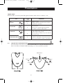
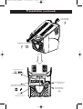
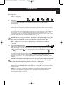
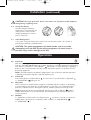
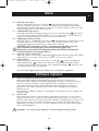
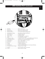
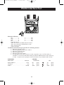
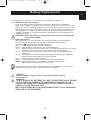
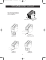
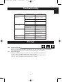
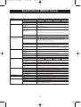
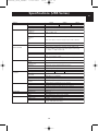
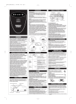
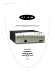
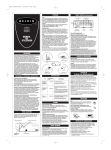
P73220uk_Gold_UPSMan
27-05-2002
15:01
Page 1
En
UPS Uninterruptible
Power Supply
User Manual
P73220uk
P73220uk_Gold_UPSMan
27-05-2002
15:01
Page 2
Important Safety Instructions
Thank you for purchasing the Belkin Uninterruptible Power Supply (UPS).
It will provide you with the best protection for your connected equipment.
Please read this manual!
This manual provides safety, installation and operating instructions that will help you obtain the
highest performance and service life that the UPS has to offer.
Please save this manual!
It includes important instructions for the safe use of this UPS and for obtaining factory service
should the proper operation of the UPS come into question.
Please save or recycle the packaging materials!
The UPS shipping materials were designed with great care to provide protection from transportation
related damage. These materials are invaluable if you ever have to return the UPS for service.
Damage sustained during transit is not covered under the warranty.
Responsible Party:
Belkin Components, Ltd.
Express Business Park • Shipton Way •
Rushden • NN10 6GL • United Kingdom
Tel: +44 (0) 1933 35 2000
Fax: +44 (0) 1933 31 2000
Belkin Components B.V.
Starparc Building • Boeing Avenue 333 •
1119PH Schiphol Rijk • The Netherlands
Tel: +31 (0) 20 654 7300
Fax: +31 (0) 20 654 7349
2
P73220uk_Gold_UPSMan
27-05-2002
15:01
Page 3
Table of Contents
En
Section
Page
1. Introduction . . . . . . . . . . . . . . . . . . . . . . . . . . . . . . . . . . . . . . . . . . . . . . . . . . . . . . . . . . . 4
2. Safety . . . . . . . . . . . . . . . . . . . . . . . . . . . . . . . . . . . . . . . . . . . . . . . . . . . . . . . . . . . . . . . . 5
3. Contents List . . . . . . . . . . . . . . . . . . . . . . . . . . . . . . . . . . . . . . . . . . . . . . . . . . . . . . . . . . . 5
4. Presentation
Front Panel . . . . . . . . . . . . . . . . . . . . . . . . . . . . . . . . . . . . . . . . . . . . . . . . . . . . . . . . . . . . 6
Rear Panel. . . . . . . . . . . . . . . . . . . . . . . . . . . . . . . . . . . . . . . . . . . . . . . . . . . . . . . . . . . . . 7
5. Installation. . . . . . . . . . . . . . . . . . . . . . . . . . . . . . . . . . . . . . . . . . . . . . . . . . . . . . . . . . . . . 9
6. Operation . . . . . . . . . . . . . . . . . . . . . . . . . . . . . . . . . . . . . . . . . . . . . . . . . . . . . . . . . . . . 10
7. Alarm . . . . . . . . . . . . . . . . . . . . . . . . . . . . . . . . . . . . . . . . . . . . . . . . . . . . . . . . . . . . . . . 11
8. Software Options . . . . . . . . . . . . . . . . . . . . . . . . . . . . . . . . . . . . . . . . . . . . . . . . . . . . . . 11
9. USB Interface Port. . . . . . . . . . . . . . . . . . . . . . . . . . . . . . . . . . . . . . . . . . . . . . . . . . . . . . 12
10. RS232 Interface Port . . . . . . . . . . . . . . . . . . . . . . . . . . . . . . . . . . . . . . . . . . . . . . . . . . . . 14
11. Battery Replacement . . . . . . . . . . . . . . . . . . . . . . . . . . . . . . . . . . . . . . . . . . . . . . . . . . . . 15
12. Troubleshooting . . . . . . . . . . . . . . . . . . . . . . . . . . . . . . . . . . . . . . . . . . . . . . . . . . . . . . . 17
13. Storage . . . . . . . . . . . . . . . . . . . . . . . . . . . . . . . . . . . . . . . . . . . . . . . . . . . . . . . . . . . . . . 17
14. Specifications
RS232 Series . . . . . . . . . . . . . . . . . . . . . . . . . . . . . . . . . . . . . . . . . . . . . . . . . . . . . . . . . . 18
USB Series. . . . . . . . . . . . . . . . . . . . . . . . . . . . . . . . . . . . . . . . . . . . . . . . . . . . . . . . . . . . 19
3
P73220uk_Gold_UPSMan
27-05-2002
15:01
Page 4
Introduction
Have you ever noticed your lights dim or flicker when you turn on your dishwasher or
air-conditioning? This common occurrence is attributed to an under-voltage of power,
also known as a BROWNOUT.
A brownout is a period of insufficient power-line voltage. It is the most common power problem,
accounting for 80% of all power disturbances. Other origins of disturbances also vary, ranging from
atmospheric phenomena such as lightening or frost, to near by devices generating interference
such as elevators, photocopy machines and machinery, not to mention human errors such as the
accidental removal of power cords or tripping of circuit breakers.
Effects: A power disturbance such as a surge, spike, swell, line noise, brownout or blackout can
deprive a computer of the power it needs to function, causing unwanted damage to your
computer, such as frozen keyboards and hard drive crashes. Such problems will cause you to
incur computer repairs, lost data and downtime.
Solution: A Belkin Uninterruptible Power Supply (UPS) with Automatic Voltage Regulation (AVR).
Typical "Stand-by" UPS units do not have AVR to increase the output voltage or decrease the
output voltage to your computer. A surge protector can only protect your computer from
over-voltages due to irregular power. Belkin UPS units protect against surges, spikes, swells,
line-noise, brownouts and blackouts!
Only a Belkin UPS with AVR can give your computer clean and consistent
power at all times.
NOTE:
There is no guarantee that interference to radio/TV will not occur in a particular installation. If this UPS causes interference to radio or television reception (this can be determined by turning the UPS power off and on), the user is encouraged to try to correct
the interference by one or more of the following measures:
• Connect the equipment to an outlet on a circuit different from that to which the
receiver is connected.
• Increase the separation distance between the equipment and the receiver.
• Reorient or relocate the receiving antenna.
4
P73220uk_Gold_UPSMan
27-05-2002
15:01
Page 5
Safety
En
CAUTION!
• To reduce the risk of electric shock, disconnect the UPS from the main power supply before
installing a computer interface signal cable. Reconnect the power cord only after signaling
interconnections have been made.
• The internal energy source (the battery) cannot be de-energised by the user. The output may
be energised when the unit is not connected to a main power supply, thus a shock hazard may
be present.
Electrical Safety
• Check that the power cord(s), plug(s), and sockets are in good condition.
• To reduce the risk of electric shock when grounding cannot be verified, disconnect the
equipment from the AC power outlet before installing or connecting to other equipment.
Reconnect the power cord only after all connections are made.
• Do not handle any kind of metallic connector before the power has been removed.
• Use one hand, whenever, possible to connect or disconnect signal cables to avoid a possible
shock from touching two surfaces with different electrical grounds.
• Connect the equipment to a three wire AC outlet (two poles plus ground). The receptacle
must be connected to an appropriate circuit protection device (fuse or circuit) breaker.
Connection to any other type of receptacle may result in a shock hazard.
WARNING: (RISK OF ELECTRIC SHOCK)
HAZARDOUS LIVE PARTS INSIDE THIS UNIT ARE energised FROM THE BATTERY
SUPPLY EVEN WHEN THE INPUT AC POWER IS NOT CONNECTED.
WARNING: (RISK OF ELECTRIC SHOCK)
DO NOT REMOVE COVER. NO USER SERVICEABLE PARTS INSIDE, PLEASE REFER
SERVICING TO QUALIFIED SERVICE PERSONNEL.
Contents List
• One Belkin Regulator Pro Gold Series UPS (325VA, 425VA, 525VA, 625VA)
• One AC Power Cable 1.8M (6ft)
• One Telephone Cable 1.8M (6ft) RJ11(425VA, 525VA, 625VA Models Only)
• One Serial Cable RS232 1.8M (6ft) (425VA, 525VA, 625VA Models Only)
• One Cable Management Rail
• One Product Manual
• One Belkin Sentry Bulldog Shutdown Management Software CD
(425VA, 525VA, 625VA Models Only)
• One Sticker (6 Languages)
• One Product/Connected Equipment/Data Recovery Warranty Sheet.
5
P73220uk_Gold_UPSMan
27-05-2002
15:01
Page 6
Presentation
FRONT PANEL
Different LEDs on the front panel will signal information when various conditions occur:
LED
4.0
ON LINE
4.1
: Light
: Flash
MEANING
Green
Utility is normal.
Utility is abnormal—AVR (Automatic Voltage
Regulation) in operation.
Yellow
UPS supplies power to outlets from
battery source.
ON BATTERY
4.2
Battery is low; the UPS will start shutdown.
The buzzer sounds an audible alarm.
Red
There is a problem with the UPS. The LED will
be lit continuously and the buzzer will sound an
audible alarm for 10 seconds.
Battery output is drawing more power than the
UPS can provide.
OVERLOAD
4.3
REPLACE BATTERY
4.4
Red
Battery is too weak or bad.
If UPS is in “On Battery” mode this means the
UPS is just testing the condition of the battery.
ON/OFF/TEST/SILENCE BUTTON
Press the button more than 3 seconds to turn the UPS on or off, press the button less
than 3 seconds to activate the UPS self-testing or to silence the back up alarm.
4.4 On/Off/Test
4.0 On Line
4.3Replace
Battery
4.1On Battery
6
4.2 Overload/Fault
P73220uk_Gold_UPSMan
27-05-2002
15:01
Page 7
Presentation (continued)
En
REAR PANEL
4.5
INTERFACE PORT
Provides both USB
or RS232
(Depending on model) to relay the signal to
support DOS®, Windows®, and other operating systems.
4.6
TELEPHONE/FAX/MODEM OR 10Base-T NETWORK PROTECTION
Telephone/Fax/Modem lines are surge protected and provide complete safety for Internet
connection. One input port
and two output
interface ports allow for two devices to
be protected (i.e. Modem and fax).
4.7
BATTERY REPLACEMENT DOOR (HOT-SWAPPABLE BATTERY)
4.8
AC INPUT POWER RECEPTACLE
4.9
AC BREAKER (CIRCUIT BREAKER)
The circuit breaker button will stick out if an overload condition forces the UPS to disconnect itself from utility power. If the button sticks out, disconnect non-essential equipment
and reset the circuit breaker.
+
4.10 BATTERY BACK-UP OUTLETS
Data sensitive equipment such as a computer, monitor, and external drive should be powered
by these outlets. Battery power is automatically provided in case of a power outage.
Power (utility or battery) is not supplied to these outlets when the UPS is switched Off.
(Do not plug surge protectors or power strips into the battery back-up outlets.)
4.11 SURGE-ONLY PROTECTED OUTLETS
Equipment such as a printer, fax machine, or scanner should be powered by these outlets.
They are rated at 1.7Kva (1104W). These outlets do not provide power during a power outage. Equipment connected to these outlets should require surge protection only but should
not require power during a power outage. These outlets are always on (when utility power is
available) and are not controlled by the front panel switch.
7
P73220uk_Gold_UPSMan
27-05-2002
15:01
Page 8
Presentation (continued)
4.11 Surge-Only
Protected outlets
4.10 Battery Back-up outlets
+
4.5 Interface Port
USB or RS232
(Depending on model)
4.8 AC Input Power
Receptacle
4.6 Telephone/Fax/Modem
or 10 base T network Protection
4.9 AC Breaker
(Circuit Breaker)
4.7 Battery
Replacement Door
8
P73220uk_Gold_UPSMan
27-05-2002
15:01
Page 9
Installation
En
a5.0 Inspection
Inspect the UPS upon receipt. The packaging is recyclable; save it for reuse or
dispose of it properly.
5.1
Placement
Install the UPS in a protected area with adequate air flow and free of excessive dust.
Do not operate the UPS where the temperature and humidity are beyond the
specified limits.
5.2
Connect to Utility
Ensure all power switches are off. Remove the power cable at the back of the computer
and plug it into the AC input at the rear of the UPS.
5.3
Connect the Loads
Connect the UPS to the computer by connecting one end of the power cord supplied, to
the AC input of your Computer and the other end to a battery backup outlet +
.
Connect the monitor to the UPS by removing the power connection from the rear of the
computer and connect it to a battery backup outlet
+
.
CAUTION: Never connect a laser printer or scanner to the backup outlets of the UPS
with other computer equipment. A laser printer or scanner periodically draws significantly more power when in use than when idle. This may overload the UPS.
NOTE : Additional AC Power Cables 1.8M (6ft) (Part No. F3A102b06) are available for
connecting additional loads to the UPS. Please contact Belkin Components for details of a
local reseller.
5.4
Connect Computer Interface
Belkin Sentry Bulldog Shutdown Management Software and the USB
or RS232
cable (depending on model) can be used with this UPS. If used, connect the interface
cable to computer interface port on the back panel of the UPS and then connect to the
USB
or Serial port
on your PC.
5.5
Connect the Telephone/Fax/Modem Lines
Connect a single-line telephone/fax/modem line into the surge protected sockets on
the back of the UPS. The RJ45/ RJ11 modular sockets accept standard single-line
telephone connections. This connection will require another length of telephone cable
(supplied).
CAUTION: The telephone/fax/modem protection feature could be rendered inoperable
if improperly installed. Make sure that the telephone line from the wall is plugged into
the connector marked: and the device or devices to be protected
(telephone/fax/modem) are plugged into the connectors marked:
NOTE:To provide surge protection for your Ethernet network an RJ45 FastCat 5™ 1.8M (6ft)
cable (Part No. A3L850b02M-BLKS) is required. Please contact Belkin Components for details
of a local reseller.
NOTE:This connection is optional but highly recommended as telephone/fax/modem
lines often carry dangerous surges and spikes. The UPS works properly without a
telephone/fax/modem connection.
9
P73220uk_Gold_UPSMan
27-05-2002
15:01
Page 10
Installation (continued)
CAUTION: This surge protection device is for indoor use only. Never install telephone
wiring during a lightning storm.
5.6
Charge the Battery
The UPS charges its battery
whenever it is connected to the
utility power. For best results,
charge the battery for 4 hours
prior to initial use.
5.7
Cable Management
It is used to corral all of the power cords into a neat and safe order. It also assists in
preventing accidental cord detachment.
CAUTION: The cable management rail should not be used as a handle.
Attempting to lift the UPS by the cable management rail could result in
personal injury and/or damage to the UPS.
Operation
6.0
Switch On
With the UPS plugged in, press and hold the on/off/test button
for more than 3 seconds
until the "ON LINE"
LED lights up to switch the UPS on. The UPS will perform self-testing
each time it is switched on. The "ONLINE "
LED remains on when the UPS is supplying
power to the connected loads. The UPS can be utilised as a master on off switch for the
protected equipment.
NOTE: The UPS maintains the battery charge when in the off position and will respond to
commands received through the computer interface port.
6.1
6.2
Switch Off
Press and hold the on/off/test button
or "ON BATTERY"
LED goes off.
for more than 3 seconds until the "ON LINE"
SELF-TEST
Use the self-test to verify both the operation of the UPS and the condition of the battery.
In normal utility power, push the on/off/test button
less than 1 second and the UPS
performs a self-test function. During the self-test, the UPS operates in back-up mode.
NOTE: During the self-test, the UPS briefly operates the loads on-battery
and the
audible alarm beeps at 15 second intervals. If the UPS passes the self-test, it returns to
on-line operation.
6.3
SILENCE
In " BACK-UP" mode, push the on/off/test button
less than 3 seconds to silence the
audible alarm. (The function is void when under condition of "LOW BATTERY"
or "OVERLOAD"
.)
10
P73220uk_Gold_UPSMan
27-05-2002
15:01
Page 11
Alarm
En
7.0
7.1
7.2
BACK-UP (slow alarm)
When in "BACK-UP" mode, the on battery
yellow LED illuminates and the UPS
sounds an audible alarm every 15 seconds. The alarm may be disabled using the Belkin
Sentry Bulldog Shutdown Management Software or as stated in step 6.3. The alarm stops
when the UPS returns to line normal operation.
LOW BATTERY (rapid alarm)
In backup mode when the battery energy runs low, the on battery Yellow
LED flashs at
1 second intervals and the audible alarm beeps at 1 second intervals until the UPS shuts
down from a depleted battery or returns to line normal operation.
OVERLOAD (continuous alarm)
When the UPS is in "OVERLOAD" the overload
red LED lights up and the UPS sounds
an audible alarm at 1 second intervals to warn of an overload condition. Disconnect
nonessential equipment from the UPS to eliminate the overload.
CAUTION: If the overload is severe , the input circuit breaker may trip
(the resettable centre plunger of the circuit breaker pops out).
Disconnect nonessential load equipment from the UPS to eliminate the
overload and press the plunger back in.
7.3
7.4
Fault (30 seconds continuously)
When the output is shorted, the "OVERLOAD"
red LED illuminates and the UPS audible
alarm beeps for 10 seconds continuously to warn of a short circuit condition.
Replace Battery
If the battery fails a self test, the UPS returns to "ONLINE"
operation and lights the
"REPLACE BATTERY"
red LED. The loads are not effected. Recharge the battery
overnight and perform the self test again. If the "REPLACE BATTERY"
red LED is still
on, the battery will need to be replaced.
Disconnect the equipment from the UPS prior to checking the equipment.
Software Options
8.0
8.1
Belkin Sentry Bulldog Shutdown Management Software
Belkin Sentry Bulldog Shutdown Management Software receives communication
through the USB or RS232 interface port (depending on model) to perform monitoring
functions, and also provide an orderly shutdown of the computer in the event of a
power failure. Moreover, Belkin Sentry Bulldog Shutdown Management Software
displays all of the diagnostic symptoms on screen, such as Voltage level, Frequency,
Battery level, etc.
The software is available for Windows® 95, Windows® 98, Windows NT® V4 or higher and
Windows® 2000.
Interface Kits
Each interface kit includes a special interface cable which is required to convert status
signals from the UPS into signals that the individual operating system can recognize. The
interface cable must be connected to the USB or RS232 port (depending on model) on the
UPS. The other side of the interface cable can be connected to the USB or RS232 port
(depending on model) of your PC. For other installation instructions and features, please
refer to the README file.
CAUTION:
Use only a factory supplied or authorized UPS monitoring cable!
11
P73220uk_Gold_UPSMan
27-05-2002
15:01
Page 12
Software Options (continued)
8.2
8.3
USB (Universal Serial Bus): HID (Human Interface Device) setup procedure
8.2.1
When the USB cable that comes with the UPS is first connected to a USB port on
your computer, the Windows® 98 dialog called ADD NEW HARDWARE WIZARD
should appear automatically. (To display this dialog manually, you can choose the
Start button and then Settings to access the Control Panel and then double-click
on ADD NEW HARDWARE. The USB cable should be connected already.)
8.2.2
THE ADD NEW HARDWARE WIZARD dialog box guides you through the
installation process. Click on “Next”.
8.2.3
A dialog states "Windows will now search for any new Plug-and-Play devices
on your system". Click “Next”.
8.2.4
A subsequent dialog gives you these options:
• Search for the best driver for your device (recommended).
• Display a list of all drivers in specific location, so you can select the driver
you want. Please accept the recommended choice by clicking on “Next”.
8.2.5
The Wizard will then search your hard drive for a file called….\INF\hiddev.inf.
This file contains all the information that Windows® 98 needs to install the correct
device drivers.
8.2.6
At this point the wizard might ask for the Windows® 98 CD-ROM. Place the
CD in the CD-ROM drive and select OK.
8.2.7
The installation process will continue automatically until a dialog displays
indicating that the drivers have been installed. Select the Finish button and
your drivers are installed.
RS232 (Serial Interface) set-up procedure
Charge the UPS 2 – 4hours before installing the software. Connect the supplied RS232
serial cable (excluding 325VA Series) to the UPS and connect the other end to a designated
port on the PC. Turn on the UPS, restart the PC and then place the supplied CD in the
CD-ROM drive.
Installing the software.
(Note: These instructions assume D: is your CD-ROM drive. If not substitute the
appropriate drive letter for D:).
8.3.1
Click the Start button on your desktop task bar, and select Run.
8.3.2
Type D:\Windows\SETUP.EXE and click OK.
8.3.3
Follow the on screen instruction commands.
USB Interface Port
The computer interface port has the following characteristics:
1.
Plug-and-Play Support
2.
Hot Attachment
3.
USB Port Protection
4.
Self Powered
5.
1.5 MBits/sec Low-Speed USB Device
6.
Compliant With USB Specification Version 1.0
7.
Compliant With HID Specification Version 1.0
8.
Compliant With HID Power Device Class Version 1.0
9.
Display UPS Status Data: Voltage Out Of Range/Buck/Boost/Frequency Out Of Range/
Overload Over Charged/Over Temperature/Internal Fail/Shutdown Request/Shutdown
Imminent Switch On/Off/Switchable/Tested Awaiting Power/Good/Beeper/Terminate
Charge/Terminate Discharge/Below Remaining Capacity-Limit/Remaining Time LimitExpired/Charging/Discharging/Fully Discharged/Need Replacement
10. Measurement Items: AC Input Voltage/AC Output Voltage/AC Input Frequency/AC Output
Frequency Battery Voltage/Battery Capacity/Temperature Percent Load
11. Control Items: Turn On/Off Outlet/Schedule Shutdown/High/Low Transfer Voltage/Battery
Test Delay Before Shutdown/Delay Before Startup/Delay Before Reboot
12
P73220uk_Gold_UPSMan
27-05-2002
15:01
Page 13
USB Interface Port (continued)
En
1.
2.
3.
4.
5.
6.
7.
8.
9.
10.
11.
12.
13.
14.
15.
16.
17.
18.
19.
20.
Firmware .....................................Version Of Firmware
Rating VA ....................................Rated Power Capacity Of UPS
Rating Voltage ............................Rated Power Voltage Of UPS
Rating Frequency........................Connected Frequency Rating Of UPS
Rating Battery Voltage ...............Rated Battery Voltage Used By UPS
Input frequency...........................AC Utility Frequency
Input voltage ..............................AC Utility Voltage
Output source.............................Indicating Bypass or On Battery
Alarm ..........................................To Set Situation For Alarm
Voltage Sensitivity ......................To Improve Transfer Time and Avoid Effect Of I/P Distortion
Outlet Relay ON/OFF... ..............Set Delay Time to Control Outlet Relay On/Off
Next Shutdown...........................Time To Next Scheduled Shutdown
Next Restart................................Time To Next Restart
AC Source...................................Input Power Source Of UPS
Battery ........................................Condition Of Battery
Loading .......................................Load Percentage Of UPS
Battery Level ...............................Indicates The Remaining Power Percentage Of Battery
Selectable Transfer Voltage ........Change Transfer Voltage
Diagram ......................................Input & Output Power Flow Of UPS
Picture.........................................General Outlook Of UPS
13
P73220uk_Gold_UPSMan
27-05-2002
15:01
Page 14
RS232 Interface Port
RS232 Pin definition:
NC ....................1
6 ....................NC
TXD...................2
7 ....................NC
RXD ..................3
8 ....................NC
NC ....................4
9 ....................NC
Signal Ground ..5
*pin2: PC receives line RS232 data from UPS.
*pin3: PC transmits line RS232 data to UPS.
*pin5: signal ground.
*other: not used.
The RS232 communication port provides the following features.
1. Monitoring charger status
2. Monitoring battery status and condition
3. Monitoring inverter status
4. Monitoring UPS status
5. Monitoring the utility status
6. Providing the power switch function for the computer to turn on/off the utility on
schedule. To save power UPS data will be provided at 2400 baud rate and is made up
of 8 bit, 1 stop bit, and no parity bit. All the information is provided in ASCII format.
HARDWARE:
BAUD RATE . . . . . . . . . . . . . . . . . 2400 bps
DATA LENGTH . . . . . . . . . . . . . . . . . . 8 bits
STOP BIT. . . . . . . . . . . . . . . . . . . . . . . 1 bit
PARITY . . . . . . . . . . . . . . . . . . . . . . . NONE
CABLING:
COMPUTER
RX
(pin2)
TX
(pin3)
GND
(pin5)
14
UPS
TX
(pin2)
RX
(pin3)
GND
(pin5)
P73220uk_Gold_UPSMan
27-05-2002
15:01
Page 15
Battery Replacement
En
The average life of a battery is 3-5 years before ever needing to be replaced.
11.0 EcoBattery Replacement Program
In the event that the UPS needs a battery replacement, Belkin offers its EcoBattery
Replacement Program. This program offers a battery replacement and full service check on
your UPS to ensure it is working properly to protect your connected devices. It also ensures
that the battery in the UPS is discarded properly in an effort to keep our environment clean.
All participants in the program will receive a two-year extended product warranty. Please
call Belkin Components for detailed information regarding the cost of the program and
shipping procedures.
CAUTION: When the battery is disconnected the loads are not protected
from power outages.
11.1 Battery Replacement
Battery replacement is a safe procedure. You may leave the UPS On and equipment
connected during this procedure. Do not replace the battery when the UPS is
‘On Battery’
. See page 15 for diagram illustrations.
11.1.1 Set the UPS at the edge of a table (Diagram a).
11.1.2 Slide the battery compartment cover down (Diagram b).
11.1.3 Grasp the battery and slide it partially out. Then grab the battery firmly and remove;
the battery wires will disconnect as the battery is pulled out (Diagram c).
11.1.4 Carefully insert the new battery halfway into the UPS. Avoid pinching the wires
(Diagram d).
11.1.5 Connect the wires to the new battery according to the following configuration:
Red wire to red terminal Black wire to black terminal
11.1.6 Carefully insert the battery terminals.
11.1.7 Slide the battery compartment cover back into place (Diagram e).
NOTE: Replacement batteries are available for all models. Please contact
Belkin Components for details of a local reseller.
The old battery must be recycled. Deliver the battery to an appropriate recycling facility.
Additional recycling information is provided with your new battery.
CAUTION:
Remove watches, rings and other metal objects when working
with batteries.
WARNING:
DO NOT DISPOSE OF BATTERIES IN A FIRE, THE BATTERIES MAY EXPLODE.
DO NOT OPEN OR TAMPER WITH THE BATTERIES. DAMAGE TO THE
PROTECTIVE OUTER SHELL CAN RELEASE THE ELECTROLYTE WHICH IS
HARMFUL TO THE SKIN AND EYES.
REPLACE BATTERIES WITH THE SAME NUMBER AND TYPE AS ORIGINALLY
INSTALLED IN THE EQUIPMENT.
15
P73220uk_Gold_UPSMan
27-05-2002
15:01
Page 16
Battery Replacement (continued)
Refer Servicing to qualified
service personnel or contact
Belkin Components.
Diagram a
Diagram b
Diagram d
Slide the battery
compartment cover.
Slide the battery back in.
Avoid pinching the wires.
Diagram c
Diagram e
Slide the battery
partially out.
Slide the battery
cover into place.
16
P73220uk_Gold_UPSMan
27-05-2002
15:02
Page 17
Troubleshooting
En
PROBLEM
POSSIBLE CAUSE
SOLUTION
On/off/test/button not
pushed or pushed less
than 3 seconds
Press the on/off/test button
more than 3 seconds
Battery voltage less than
10V
Recharge the UPS at least
4 hours
UPS fault
Contact service personnel
Power cord loose
Replug the power cord
AC breaker is burned out
Replace the breaker
Line voltage too high, too
low or black out
Normal condition
Battery not fully charged
Recharge the UPS at
least 4 hours
UPS is overloaded
Remove some
unnecessary loads
Charger fault or
other reason
Replace battery
The UPS continuously
beeps
Overload
Remove the
non-critical loads
Red LED lit
Battery failure
Replace battery
UPS not on
LED not lit
UPS always at
battery mode
Back up time too short
Storage
13.0
13.1
Storage Conditions
Store the UPS covered and upright in a cool, dry location, with its battery fully charged.
Before storing, charge the UPS for at least 4 hours. Disconnect any cables connected to
the computer interface port to avoid unnecessary drainage of the battery.
Extended Storage
During extended storage in environments where the ambient temperature is
-15°C to +30°C, charge the UPS battery every 6 months.
During extended storage in environments where the ambient temperature is
+30°C to +45°C, charge the UPS battery every 3 months.
17
P73220uk_Gold_UPSMan
27-05-2002
15:02
Page 18
Specifications (RS232 Series)
MODEL
INPUT
OUTPUT
PROTECTION
AND FILTERING
BATTERY
PHYSICAL
ALARM
INTERFACE
CONFORMANCE
ENVIRONMENT
Capacity
Voltage
Frequency
Voltage
(on battery)
Frequency
(on battery)
325VA
425VA
525VA
325VA(211W) 425VA(255W)
525VA(315W)
187 Vac - 280 Vac
50Hz or 60Hz ±3Hz (auto sensing)
Simulated sine wave, 230Vac±8%
625VA
625VA(375W)
50Hz or 60Hz ±1Hz
Voltage
Regulation
AVR
Smart boost increases 14.8% of voltage if input is 213 to 187 Vac.
Transfer Time
< 4 milliseconds, including detection time
320 Joules
Spike Protection
Smart trim reduces 12.8% of voltage if input is 247 to 280 Vac
Overload Protection
UPS automatic shutdown if overload exceeds 130% in AC
mode and 100% in back-up mode. UPS alarms continuously
in > 107% or <130% in AC mode.
Unit Input
Modem/Network
Breaker for overload and short circuit protection
Single Line (2 Wire, RJ11) Network (UTP, RJ45) compatible
jacks, one input/two output except 325 Series
Short Circuit
UPS output cut off immediately or input breaker protection
Type
Sealed, maintenance-free lead acid
Typical
Recharge Time
Protection
4 hours (to 90% of full capacity)
Back up Time
Full/half load
Net Weight
Dimension
(mm) WDH
Input inlet
Output outlet (UPS)
Output outlet
(Bypass)
Battery Back-Up
Battery Low
Overload
Fault
Battery test
RS232 Interface
Safety
Surge
Ambient operation
Audible noise
Storage condition
Automatic self-test and discharge protection,
replace battery indicator
Depending on computer load...
5-17 min
5-32 min
5-24 min.
6.5 kg/14.3lbs. 7.3 kg/16lbs
7.3 kg/16lbs
289 x 243 x 325
5-41 min.
7.3 kg/16lbs
10A/250V*1pcs, EN60320
10A/250V*4pcs; EN60320/F
10A/250V*4pcs; EN60320/F
Slow beeping sound (about 15 sec. interval)
Rapid beeping sound (about 1 sec. interval)
Continuous beeping sound (about 1 sec. interval)
10 sec. beeping sound continuously
Slow beeping sound (about 15 sec. interval)
RS232 Port (except 325VA Series)
CE, TUV/GS, TUV/EMC,EN5009-1-1-1, EN50091-2, EN50082-1
Meet IEEE C62.41. Category A standard
0~95%, humidity non-condensing, 0~40°C
<40dBA (1 meter from surface)
-15°C – 40°C (with battery)
-15°C – 70°C (without battery)
18
P73220uk_Gold_UPSMan
27-05-2002
15:02
Page 19
Specifications (USB Series)
En
MODEL
INPUT
OUTPUT
PROTECTION
AND FILTERING
BATTERY
PHYSICAL
ALARM
INTERFACE
CONFORMANCE
ENVIRONMENT
Capacity
Voltage
Frequency
Voltage
(on battery)
Frequency
(on battery)
350VA
500VA
350VA(227W)
500VA(300W)
187 Vac - 280 Vac
50Hz or 60Hz ±3Hz (auto sensing)
Simulated sine wave, 230 Vac±8%
650VA
650VA(390W)
50Hz or 60Hz ±1Hz
Voltage
Regulation
AVR
Smart boost increases 14.8% of voltage if input is 213 to 187 Vac.
Transfer Time
< 4 milliseconds, including detection time
150 Joules
Spike Protection
Smart trim reduces 12.8% of voltage if input is 247 to 288 Vac
Overload Protection
UPS automatic shutdown if overload exceeds 130% in AC
mode and 100% in back-up mode. UPS alarms continuously
in > 107% or <130% in AC mode.
Unit Input
Modem/Network
Breaker for overload and short circuit protection
Single Line (2 Wire, RJ11) Network (UTP, RJ45) compatible
jacks, one input/two output
Short Circuit
UPS output cut off immediately or input breaker protection
Type
Sealed, maintenance-free lead acid
Typical
Recharge Time
Protection
4 hours (to 90% of full capacity)
Back up Time
Full/half load
Net Weight
Dimension
(mm) WDH
Input inlet
Output outlet (UPS)
Output outlet
(Bypass)
Battery Back-Up
Battery Low
Overload
Fault
Battery test
USB Interface
Safety
Surge
Ambient operation
Audible noise
Storage condition
Automatic self-test and discharge protection,
replace battery indicator
Depending on computer load...
5-20 min
5-45 min
5-30 min.
5.5kg/12.3lbs. 6kg/13.23lbs
6.5kg/14.33lbs.
289 x 243 x 325
10A/250V*1pcs, EN60320
10A/250V*4pcs; ENG60320/F
10A/250V*4pcs; ENG60320/F
Slow beeping sound (about 15 sec. interval)
Rapid beeping sound (about 1 sec. interval)
Continuous beeping sound (about 1 sec. interval)
10 sec. beeping sound continuously
Slow beeping sound (about 15 sec. interval)
USB Port
CE, TUV/GS, TUV/EMC,EN5009-1-1-1, EN50091-2, EN50082-1
Meet IEEE C62.41. Category A standard
0~95%, humidity non-condensing, 0~40°C
<40dBA (1 meter from surface)
-15°C – 40°C (with battery)
-15°C – 70°C (without battery)
19
P73220uk_Gold_UPSMan
27-05-2002
15:02
Page 20
Information
CE Declaration of Conformity
We, Belkin Components, declare under our sole responsibility that the F6C350-USB/F6C500USB/F6C650-USB/ F6C325-220V/F6C425-220V/F6C525-220V/F6C625-220V to which this
declaration relates, is in conformity with Generic Emissions Standard EN50081-1 and with
Generic Immunity Standard EN50082-1 1992.
Belkin Components Two Year Product Warranty
Belkin Components warrants this product against defects in materials and workmanship for two
years. If a defect is discovered, Belkin will, at its option, repair or replace the product at no
charge, provided it is returned during the warranty period, with transportation charges prepaid,
to Belkin Components following the procedure specified in the warranty sheet. Proof of purchase
may be required.
This warranty does not apply if the product has been damaged by accident, abuse, misuse, or
misapplication; if the product has been modified without the written permission of Belkin; or if
any Belkin serial number has been removed or defaced.
THE WARRANTY AND REMEDIES SET FORTH ABOVE ARE EXCLUSIVE IN LIEU OF ALL
OTHERS, WHETHER ORAL OR WRITTEN, EXPRESSED OR IMPLIED. BELKIN SPECIFICALLY
DISCLAIMS ANY AND ALL IMPLIED WARRANTIES, INCLUDING, WITHOUT LIMITATION,
WARRANTIES OF MERCHANTABILITY AND FITNESS FOR A PARTICULAR PURPOSE.
No Belkin dealer, agent, or employee is authorised to make any modification, extension,
or addition to this warranty.
BELKIN IS NOT RESPONSIBLE FOR SPECIAL, INCIDENTAL, OR CONSEQUENTIAL DAMAGES
RESULTING FROM ANY BREACH OF WARRANTY, OR UNDER ANY OTHER LEGAL THEORY,
INCLUDING BUT NOT LIMITED TO LOST PROFITS, DOWNTIME, GOODWILL, DAMAGE TO OR
REPROGRAMMING, OR REPRODUCING ANY PROGRAM OR DATA STORED IN OR USED WITH
BELKIN PRODUCTS.
belkin.com
Belkin Components
501 West Walnut Street •
Compton • CA •
90220-5221 • USA
Tel: +1 310 898 1100
Fax: +1 310 898 1111
Belkin Components, Ltd.
Express Building Park •
Shipton way • Rushden•
NN10 6GL • United Kingdom
Phone +44 (0) 1933 35 2000
Fax: +44 (0) 1933 31 2000
Belkin Components B.V.
Starparc Building • Boeing Avenue 333
• 1119 PH Schiphol-Rijk
• The Netherlands
Tel +31 (0) 20 654 7300
Fax +31 (0) 20 654 7349
© 2002 Belkin Components. All rights reserved. All trade names are registered trademarks of the respective manufacturers listed.