1
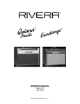
OWNERS MANUAL
Version 1.0
December, 2001
Knucklehead Reverb 1.0 p 1
Introduction
Your Rivera Amp Is An Important Part Of Your Sound
Your sound is your signature, your mark, your voice. An amp only deserves to have
your guitar plugged into it if it can deliver the tone you want—and, of course, the
dependability you need. It's as simple as that. And it's exactly why you bought your
RIVERA amp. For that, we thank you, and we're confident that you'll enjoy your amp for
years to come.
Many factors go into creating a great amp—experience, an understanding of what
guitarists want, and a lot of hard work. You'll notice that tone isn't on any parts list.
Roadworthiness isn't, either. And there's no law saying that an amp must sound good
or be well-made. But we dedicate ourselves to making the best-sounding, most reliable
amplifiers anywhere. That's why we use only the highest-quality components,
regardless of price. Such features as metal jacks, ultra-strong dadoed cabinet
construction, and highest-quality electronic components are part of our uncompromising
approach. They're chosen for their precision, strength, and ability to withstand the
rigors of years of use—and occasional abuse—on the stage and in the studio. No
compromises are made because cutting any corners—no matter how small—means
settling for second best. This is the premise and promise by which we make amps.
This requires dedication to you, the guitarist, and a belief that an amp is more than a
collection of parts. It's part of your sound.
Please fill in the following information for future reference:
Model Name: Knucklehead Reverb 55 or 100
Model Number: KR 55T, KR 100 T
Serial Number:
Dealer's Name:
Dealer's Address:
Date of Purchase:
Rivera Research & Development Corporation
13310 Ralston Ave.
Sylmar, CA 91342 USA
Ph: (818) 833-7066
Fax: (818) 833-9656
Email: [email protected]
Web: http://www.rivera.com
Knucklehead Reverb 1.0 p 2
Packing Information
Unpacking
Before you plug in, inspect your Knucklehead Reverb amp for any damage. Your amp
was inspected and sound-tested before shipment, but transportation can sometimes be
tough. Check that the Head Master MIDI Controller and power cord have been shipped
with the amp. If parts are missing, or if any damage has occurred, contact your dealer.
Packing Materials
We designed the original box and packing materials to protect your amp during
shipment. Save them. If you ever need to send your amp to us or to anyone else, the
original box and packing materials will ensure safe transit.
Safety
Throughout this manual, the lightning flash with an arrowhead symbol
within a triangle is intended to alert you to the presence of un-insulated
"dangerous voltages" within the product's enclosure that may be of
sufficient magnitude to constitute a risk of electric shock to persons.
Warning: There are no user-serviceable parts inside of this amplifier.
Warning: To avoid the risk of shock or fire, do not expose this amplifier to moisture. Do
not remove the chassis from its cabinet, or remove metal covers from chassis parts.
Removing the chassis from its cabinet exposes extremely dangerous high voltages.
There are no user-serviceable parts inside. Hazardous voltages are present inside the
chassis. Refer all servicing to qualified personnel.
The exclamation point within a triangle is intended to alert the user to
the presence of important operating and maintenance (servicing)
instructions in the literature that accompanies the product.
Caution: To avoid a fire hazard, always replace the fuses with the same type and
rating.
Caution: Always replace the line cord (mains supply) with the proper type.
Caution: Always turn off the amplifier before making or unplugging any speaker
connections.
Always transport your amplifier securely, preferably in a suitable flight case or packing
carton. Before operating your amplifier, be sure the speakers used are properly
connected. For countries where 220 to 240 volts AC is encountered, make sure that
Knucklehead Reverb 1.0 p 3
you have the correct power cord. Our 230-volt export unit can be used with any of
these voltages. For the United Kingdom, South Africa, Australia, and New Zealand, we
build a special 250V version able to handle higher Mains voltages. For Japan 100 VAC
models, all instructions for the 115 VAC models apply.
In the event that you have questions, comments, or suggestions, please contact us at:
Rivera Research & Development Corporation
13310 Ralston Ave.
Sylmar, CA 91342 USA
pH: (818) 833-7066
Fax: (818) 833-9656
Email: [email protected]
Web: http://www.rivera.com
No Time To Read The Manual?
At Least Read This Part Now!
Before you plug in:
Take a quick look inside the back of your amp. Make sure of the following:
The tubes are securely seated in their sockets.
A speaker cord is plugged into the Speaker 1 output (this jack must always be used
first) and the input jack on a speaker cabinet with a minimum impedance of 4 ohms.
The impedance selector is set to match the cabinet's impedance.
The power cord is plugged in.
Now look at the front to make sure:
The Volume and Master controls are set at low levels ('2' is a good starting point).
The Power switch is off (the lower half is pushed in).
The Standby switch is set to standby mode (the lower half is pushed in).
Plug in!
Now plug the amp into the wall, plug your guitar into either input jack, and set your
controls to one of the Quick Start settings outlined here. Then turn on the Power
switch. Wait for about a minute for the tubes to warm up. Turn on the Standby switch.
Now it's time to rock.
After you've played with your Knucklehead Reverb for a while, check out the rest of the
manual for some good tips on getting the most out of your amp.
Knucklehead Reverb 1.0 p 4
Quick Start Settings
If you're looking for a good starting point, try these settings. Remember that every
guitar and speaker cabinet sounds different, so try both inputs, and adjust the Focus
and Presence to suit your taste. These diagrams include settings for the Subwoofer. If
the Sub is NOT used, set the SUB LEVEL to 1 and PUSH it in.
Paul Jr's Settings – Use High Gain Input
PULLED
5
76
10
1
765
98
10
10
1
76
8
432
543
MASTER 2
MASTER 3
654
7
98
987
1
76
65
7
98
1
10
10 9 8
SUB LEVEL
10
765
98
SCOOP
32
54
87
BOOST
321
9
PULL
BOOST
10
321
10 9
21
32
PUSH
HI-PASS
654
43
10
32
10
PUSHED
1 10
1
GAIN
TREBLE
PUSH
432
PRESENCE FOCUS
432
PULL
21
654
321
654
987
1
POWER AMPLIFIER
PUSHED
987
1 10
PULLED
MIDDLE
BASS
MASTER
43
PUSH
BRIGHT CHANNEL 1
654
GAIN
765
432
987
654
GAIN
21
876
BASS
543
21
10 9
765
9
10 8
PULL
CONTOUR NOTCH
BOOST
9
10 8
CHANNEL 3 CHANNEL 2
PULL
PULL
PUSH
32
PUSH
98
PUSH
TREBLE
MIDDLE
Web Guy Craig's Settings – Use Low Gain Input
654
10
1
6
654
98
10
76
10 9
8
1
10 9
32
TREBLE
987
1
21
987
10 9
987
Knucklehead Reverb 1.0 p 5
43
MASTER 2
765
MASTER 3
10
10
3
21
SUB LEVEL
9
10 8
10
32
654
876
654
SCOOP
654
PULL
BOOST
1
PUSH
BOOST
32
876
987
65
54
PUSHED
HI-PASS
1
54
321
87
98
7
10
GAIN
TREBLE
PUSH
54
876
76
5
21
32
1
PUSHED
10 9
MIDDLE
BASS
MASTER
987
654
321
PUSH
BRIGHT CHANNEL 1
PULL
10 9
43
PRESENCE FOCUS
32
10
POWER AMPLIFIER
PULL
CONTOUR NOTCH
BOOST
765
PULLED
PULL
1
GAIN
PULLED
10 9 8
PULL
432
21
GAIN
21
543
3
1 10
BASS
54
PULLED
PUSH
32
CHANNEL 3 CHANNEL 2
432
PUSHED
PUSH
987
PUSH
MIDDLE
Clean Deluxe – Use Low Gain Input
MASTER
MIDDLE
PULL
PULL
76
98
543
8
765
10
65
BASS
PUSH
BRIGHT CHANNEL 1
432
7
6
87
98
321
17069
7 36
4
58
54
1
10
543
10 9
98
PULL
98
1
10
PULLED
CONTOUR NOTCH
21
SUB LEVEL
PULL
21
10 9
PULLED
PULL
432
43
25 1
PULLED
1 10
BOOST
876
PRESENCE FOCUS
HI-PASS
120 91 8
432
432
765
765
PUSH
1
POWER AMPLIFIER
PULL
10 9
PULLED
TREBLE
GAIN
PULL
PUSH
Austin Blues – Use High Gain Input
MIDDLE
87
654
9
10
1
98
10
6
35
10
32
4
10
98
87
79 68
1
10
1
1
10 9
46
57
1
BASS
MASTER
987
321
SUB LEVEL
765
654
654
65
32
PRESENCE FOCUS
543
432
765
21
24 13 2
987
BRIGHT CHANNEL 1
CONTOUR NOTCH
432
BOOST
110 9 180
987
PUSH
HI-PASS
32
POWER AMPLIFIER
PUSHED
PULL
10
PULLED
GAIN
TREBLE
80's Scoop – Use High Gain Input
PULLED
MIDDLE
876
10 9
10
987
1
5
43
10
1
7
1
4
87
65
98
54
32
32
TREBLE
76
MASTER 2
21
32
SUB LEVEL
987
654
54
PRESENCE FOCUS
65
432
109
876
876
321
321
10 9
10 9
BASS
543
CHANNEL 2
10 9 8
PUSH
SCOOP
654
PULL
BOOST
1 10
PUSH
HI-PASS
21
POWER AMPLIFIER
PUSHED
PULL
GAIN
Fast Aggressive – Use High Gain Input
PULLED
Knucklehead Reverb 1.0 p 6
MIDDLE
BASS
1
10 9
32
21
543
10 9
5
4
87
98
76
98
65
21
TREBLE
76
MASTER 3
9
10 8
43
SUB LEVEL
21
876
876
1
10
432
765
10
321
543
1
CHANNEL 3
10 9 8
PUSH
SCOOP
1 10
32
PRESENCE FOCUS
PULL
BOOST
109
654
432
765
987
PUSH
HI-PASS
54
POWER AMPLIFIER
PUSHED
PULL
GAIN
New Metal Crunch – Use High Gain Input
PULLED
1
21
10 9
87
76
8
10 9
43
9
5
21
9
987
32
MIDDLE
10
10
TREBLE
MASTER 3
10 9 8
65
SUB LEVEL
543
21
21
21
PRESENCE FOCUS
876
10
654
87
654
543
10 9
PUSH
CHANNEL 3
321
10 9
PULL
SCOOP
76
PUSH
BOOST
321
543
543
876
876
PULL
HI-PASS
BASS
4
POWER AMPLIFIER
GAIN
Lead – Use High Gain Input
PUSHED
PULLED
98
10
876
10 9
1 10
9
54
432
21
876
10
32
1
765
10 9
MIDDLE
TREBLE
MASTER 3
54
21
SUB LEVEL
876
3
4
32
PRESENCE FOCUS
987
65
87
654
321
10
21
3
10 9
10
CHANNEL 3
987
654
65
1
PUSH
SCOOP
BASS
432
PULL
BOOST
543
987
PUSH
HI-PASS
1
POWER AMPLIFIER
PULL
GAIN
Front Panel
BASS
MIDDLE
PUSH
TREBLE
43
21
5
43
21
5
43
5
43
5
43
5
43
5
43
5
43
5
43
5
43
5
43
43
76
76
43
43
76
76
43
43
76
5
76
5
76
5
76
5
76
5
76
76
5
76
MASTER
76
GAIN
PULL
BRIGHT CHANNEL 1
INPUTS
10 9 8
GAIN
21
10 9 8
43
PULL
NOTCH
21
10 9 8
76
5
PULL
CONTOUR
21
10 9 8
BASS
PUSH
BOOST
PUSH
21
10 9 8
MIDDLE
21
10 9 8
TREBLE
21
10 9 8
MASTER 2
21
10 9 8
MASTER 3
PUSH
CHANNEL 3 CHANNEL 3
SCOOP
21
10 9 8
REVERB
21
76
PUSH
BOOST
21
76
PUSH
BOOST
21
10 9 8
REVERB
PULL
PUSH
CH.1
10 9 8
21
10 9 8
SUB LEVEL
CH.2/3
10 9 8
PRESENCE FOCUS
21
10 9 8
HANDCRAFTED BY
RIVERA RESEARCH & DEVELOPMENT
SYLMAR, CALIFORNIA USA
HI-PASS
10 9 8
STANDBY
21
10 9 8
POWER
10 9 8
21
76
PULL
POWER AMPLIFIER
GAIN
LOW
GAIN
HIGH
GAIN
High Gain input
This is a high-sensitivity input. If your guitar has hot pickups, then plugging into it
makes it easy to overdrive the preamp section, creating harmonic distortion. Guitars
equipped with low-output pickups seem hotter than usual when plugged into this input.
Low Gain input
This is a low-sensitivity input. Guitars plugged into it have more headroom before
distortion sets in (meaning that you can crank up a channel's volume a little louder
before you experience Preamp distortion). This is a good choice for a clean overall
sound, and is especially well-suited to active pickups or guitars equipped with preamps.
Channel 1
Channel 1 is extremely flexible, with a flavor that brings to mind the great classic
American tones and textures. You can get some pretty impressive blues overdrive
distortion out of Channel 1, and as a rhythm channel it brings out every subtlety of your
playing. The range of tones can be anywhere from sparkling-clean to perfect for bluesy
rhythm—the kind of sound that has an attitude and gets meaner as you pick harder.
Knucklehead Reverb 1.0 p 7
Gain (with channel-select Push-Switch)
The Gain knob regulates the Preamp's volume and works with the Master to set the
level and distortion amount. A simple rule of thumb is, the higher the Gain is set, the
more distortion you get.
Treble (with Pull Bright switch)
This Treble control is similar in operation to the one on Channel 2/3. In addition, it has a
built-in Pull Bright switch. When pulled out, it adds bright highlights to the tone. As the
Gain control is increased past about '5', the bright switch's effectiveness will be
decreased.
Middle (with Pull Notch switch)
The midrange circuit has a slight notch in the frequency spectrum at about 550 Hz, and
turning the knob alters the depth of that notch. Its Pull Notch switch shifts the frequency
center of that notch down to about 250 Hz. (For reference, most 1950s tweed amps as
well as many British amps have their notch centered at 550 Hz, while classic
"blackface" American amps have theirs centered at 250 Hz.). Experiment with this,
especially if you're looking for a uniquely expressive rhythm texture.
Bass (with Pull Contour switch)
The "chunk" and support that form the backbone of your tone come from this control.
Pulling the Bass control out will engage a special "Contour" circuit thereby enhancing
bottom end, especially useful with thin sounding guitars where more bottom end is
required for a great comping tone. Also, when using a singled coil guitar for a jazz or
bebop tone, this control will add the needed fatness to the lower strings.
Master (with Push Boost switch)
Channel 1 has a special EQ circuit that works in conjunction with the distortion circuit to
sweeten the tone. Therefore, the Master knob's effect goes beyond loudness control.
Try it with different Gain and Middle settings to adjust the amount of "singing" and "grit".
The Boost, activated by pushing the Master knob, is a sweet-sounding boost
characterized by a more subtle effect on the harmonics than Channel 2's Boost control
while adding sustain. The Ch.1 Boost helps to drive the power amp, and the best
description of its influence over the tone is that it thickens it.
Channel 2
All three channels are voiced differently, and Channel 2 is definitely geared toward
creating impressive and massive crunch and lead tones (think of it as a great "British"
tone). Grit, grunge, dirt—whatever you're looking for in the distortion department is
here, from sweet and singing to hard-driving to maximum sustain. Note: Like the
controls on all classic amps, the Treble, Middle, and Bass interact, creating smooth,
musical tone changes. All three controls operate with even response throughout their
ranges. This amp has so much potential gain and sustain, you should not assume that
the Gain controls should be set on a typical '10' to start with. You might try 3-5 as a
starting point. This is also applies to Channel 3.
Knucklehead Reverb 1.0 p 8
Gain (with channel-select Push-Switch)
Although it's labeled "Gain," this control does a lot more than determine how loud
Channel 2 is. It regulates the Preamp's volume and works with the Master to set the
level and distortion amount. A simple rule of thumb is, the higher the Gain is set, the
more distortion you get. The push switch selects which channel is active. Its circuitry is
designed so that you don't hear a loud pop or click when the channel is changed.
Bass
The "chunk" and support that form the backbone of your tone come from this control.
Its effect on your overall sound will be different at high and low volumes due to the
speaker's characteristics and how much distortion you use. The bass EQ curve has
been specially tailored to complement the maximum bass response of the RIVERA
Knucklehead 412-Cab (T/B) speaker enclosures.
Middle (with scoop Pull-Switch)
The midrange circuit provides the "meat" that fills out your sound. Two notch
frequencies are available-550Hz (when pushed in), and 750 Hz (when pulled out).
Notch is the hinge point of the Bass and Treble controls. Think of it as a valley between
two mountains on a graph. Turning the knob alters the depth of that notch, letting you
dramatically change the overall voicing of your tone. Vintage Tweed and Plexi British is
typically at 550 Hz. Modern lead sounds are often EQ’d in the studio to 750 Hz dip.
Adjust to your taste.
Treble
Whether you're looking for edge, slash, or just a little shimmer, this knob's for you. Like
the Bass control, the apparent effect of the Treble changes with the loudness and
distortion you dial in.
Master (with Push Boost switch)
Think of the Master as a sort of governor that sets the maximum loudness for the
channel. Also, think of it as the second half of what the Gain knob does. With the Gain
turned down and the Master up, there's less distortion than if you crank up the Gain and
set the Master lower. The Master control comes after all distortion and tone-shaping on
Channel 2, so its level doesn't have a bearing on your basic tone. When you push the
Boost switch on Channel 2, it adds a whole range of harmonics, and not just gain. This
is easy to hear by playing a power chord and comparing its sound with the switch
pushed in and pulled out. With the switch activated, the tone blooms, going from fat to
ferocious.
Channel 3
Channel 3 shares the EQ with Channel 2, but is a different texture of distortion and gain.
A extra section of a Preamp Tube is switched into the circuit for Channel 3. Identical in
controls, EQ, and features, it's difference lies in it's internal circuitry and distortion
textures. Different music can at time require a different fabric of harmonics and
textures. Many players have said that the tone is more greasy and more hard-core.
Like Channel 2, all of the descriptions of the features and the instructions for their usage
apply. Because of the extra tube stages involved in the circuits, the attack and
compression response also differs from Channel 2. Just try it and you will hear.
Knucklehead Reverb 1.0 p 9
Sub Level Output (with high pass Pull-Switch)
This control is a RIVERA exclusive feature. This control varies the output level of the
Sub Woofer output circuitry the feeds a full range low source impedance signal to Sub
Woofer Output jack (see rear panel features) to an external Powered Sub, like our Sub
1 or Sub 2 powered Sub Woofer cabinets. It also can be used as an Auxiliary Send to a
Mixer, Recorder, PA System, and a sub-Woofer system that utilizes it’s own electronic
crossover and separate power amp, like our Rivera LB-212 Sub Cab and a Rivera TBR5, 320W Power Amp (requires a separate non-Rivera made electronic crossover). This
signal is dry, meaning any signal present in the effects loop return, will not be in the
signal stream from this jack. The internal power amp of the Knucklehead Reverb is
normally a full range signal, with all of the frequencies of the amplifier powering the
Speaker Output jacks. When the Sub Level control is pulled, a high pass filter
frequency dividing network is activated, with the internal power amp only reproducing
the frequencies higher than the frequencies that the Sub 1 or Sub 2 powered SubWoofers are optimized for. This gives you an increase in dynamic range and definition
of the normal speakers connected to the Knucklehead Reverb. This is because they no
longer have to handle the fatiguing low frequency energy. This switch was provided for
players to have a choice in tones, or to be able to use the Knucklehead Reverb without
a subwoofer speaker system.
Focus
This control is another RIVERA exclusive that actually lets you change the speaker's
response characteristics, from tight to loose. The effect can give closed-back cabinets
a sound more akin to an open one, and vice-versa, plus you can "custom blend" the
amount of hardness your final sound has. This function is independent of the use of the
Sub Woofer Output, and even with the Sub Level control pulled, it will continue to affect
the Knucklehead Reverb speaker output damping.
Presence
The Presence control is incorporated as a vital part of the power amp section. Think of
it as a final brightness control after all the EQ, distortion and effects.
Standby
By turning the Power on and the Standby off (the down position, labeled with a '0'), you
can warm up the amplifier before applying full voltage to the Preamp and power output
tubes. This prolongs tube life. Using the Standby switch when you're taking a break
also helps to extend the tubes' life, plus it keeps the amp constantly at the ready. Just
flip the Standby switch to the up ('I') position, and you're ready to play.
Power
This is your main power switch. The on position is indicated by the light being
illuminated. The off position is marked by the "0" on the switch. Before turning the amp
on, always check that a speaker is connected and that the power cord is firmly plugged
into the amp and the outlet.
Knucklehead Reverb 1.0 p 10
Rear Panel
76
Z OUT
560 Ω
Z IN
250K Ω
LOOP BLEND
RIVERA RESEARCH & DEVELOPMENT CORP. SYLMAR, CA, USA 91342
SUB OUTPUT
RECORDING
OUTPUT
PUSH LOOP
IMPEDANCE
SELECTOR
100W. RMS
SPEAKER JACKS
IN PARALLEL
8
4
43
21
5
43
5
43
21
SPEAKER 2
Z OUT
560 Ω
Z OUT
560 Ω
CAUTION: CHASSIS SURFACE HOT.
CAUTION
SPEAKER 1
USE FIRST
TOTAL
MIN. Z 4 Ω
HIGH
TO REDUCE THE RISK OF ELECTRIC
SHOCK, DO NOT REMOVE CHASSIS
POWER CLASS
VINTAGE / MODERN
16
5
RETURN
LEVEL
10 9 8
2
RETURN
10 9 8
15 0 1
MIDI
CAUTION: NO USER SERVICEABLE PARTS INSIDE.
REFER SERVICING TO QUALIFIED PERSONNEL.
EFFECTS LOOP
SEND
10 9 8
21
11 12 13 14
3 4 5 6
SEND
LEVEL
76
RIVERA MIDI
PEDAL ONLY
76
MIDI
IN
OUTPUT
POWER
H.T.
FUSE
MAINS
FUSE
S
FU E
S
FU E
S
FU E
MIDI
OUT/THRU
10
7 8 9
1A 250V
SLO-BLO
SERIAL NUMBER
LOW
MAINS INPUT
115V
60Hz
INPUT
POWER
440 WATTS
S
FU E
CHAN
SELECT
4A-250V
SLO-BLO
REPLACE FUSE WITH SAME
TYPE AND RATING.
Patents
Applied for.
MODEL KNUCKLEHEAD REVERB
MIDI Connectors
CHAN
SELECT
RIVERA MIDI
PEDAL ONLY
2
11 12 13 14
3 4 5 6
MIDI
IN
10
7 8 9
MIDI
OUT/THRU
15 0 1
MIDI
CAUTION: NO USER SERVICEABLE PARTS INSIDE.
REFER SERVICING TO QUALIFIED PERSONNEL.
MIDI THRU
Standard MIDI thru, passes data from the MIDI IN to additional MIDI gear.
MIDI IN
Standard MIDI input. Use this to connect any standard MIDI controller.
Special Combo MIDI In And DC Power Out
This connector is labeled "RIVERA MIDI PEDAL ONLY"
On earlier versions of the Knucklehead, this connector is labeled "FTSWITCH FS-9
ONLY". (The original name for the Head Master was the FS-9). The function is exactly
the same, only the label is different.
In addition to being a standard MIDI IN, this connector ALSO provides DC power to the
Head Master.
Even though the MIDI connector has 5 pins, only 3 of them are used. The other two are
undefined by the MIDI specification and unused by most MIDI gear. The Knucklehead,
and all future Rivera MIDI enabled amps, provides DC power on these pins.
Warning: This connector should ONLY be used to connect the Head
Master or other Rivera MIDI pedal. There is no agreement among
manufacturers on the use of these two pins. Some manufacturers also
use them to provide power, but it may be a different voltage or polarity.
If you plug a cable from the special Combo connector into another
device, and that device ALSO uses these pins , BOTH devices may be damaged!
Knucklehead Reverb 1.0 p 11
Midi Cables For The Special Combo Connector
Even though the MIDI specification only defines three pins, most manufacturers of MIDI
cables provide all five wires. This means that most normal MIDI cables will work
correctly in the special connector. However, if you find a MIDI cable that only has 3
wires, it will not work.
A Few Thoughts On Non-Standard Connectors
When we designed the Head Master, we faced a difficult decision. We wanted to supply
power to the pedal from the amplifier using one cable for both power and MIDI. We then
had two choices - Use a standard MIDI connector in a non-standard way, or use a nonMIDI connector.
If we had used a non-MIDI connector, the unit would have been more foolproof. The
special combo MIDI and Power connector could ONLY be connected using the special
cable. There would be no way to hook it up incorrectly.
But then we thought about the poor guy on the road, far from a well-stocked music
store. If his special cable failed, he would be out of luck. We decided to use a standard
MIDI connector and cable in a non-standard way because it is very easy to find a
replacement.
Of course, the downside of this decision is that it is possible to connect our nonstandard connector to a standard MIDI connector. If the MIDI device only uses the three
standard pins, there will be no problem. However, some manufacturers have also used
the two extra pins for their own special non-MIDI functions. We believed that if we
warned the users to hook up the cables according to the instructions, they would accept
this tradeoff.
The Two Midi Inputs Are Not A Midi Merger!
The Knucklehead has two MIDI inputs - one regular MIDI IN and a special Combo MIDI
IN and DC Power Out.
The special Combo connector is used with the Rivera Head Master.
The standard MIDI IN is used with other MIDI controllers.
WARNING: DO NOT USE BOTH INPUTS AT THE SAME TIME!
The Knucklehead DOES NOT contain a MIDI MERGE function!
Knucklehead Reverb 1.0 p 12
The Midi Channel Selector Switch
3 4 5 6
11 12 13 14
2
10
7 8 9
15 0 1
The Knucklehead uses a rotary switch to select the MIDI channel. It is a high quality
switch, and is much easier to use than the DIP switches used by some manufacturers.
Unfortunately, it is numbered in a way that can create confusion.
As shown on the diagram, the switch is numbered from 0-15.
Most MIDI devices define the MIDI channels as 1-16
So, it is necessary to add 1 to the number on the switch to get the MIDI channel
SWITCH POSITION 5 = MIDI CHANNEL 6
So, why is the switch labeled wrong?
In the world of electronics and programming, it is not labeled wrong.
It selects one of 16 four digit binary numbers, 0-15 is 0000-1111 in binary.
It is labeled correctly for what it does.
Internally, MIDI gear uses channels 0-15.
Long ago, MIDI manufacturers decided that musicians would be uncomfortable.
with channel zero, so they decided to add a 1 to the actual value.
Counting From Zero
As you may or may not know, computer programmers start counting from zero instead
of one.
Most people would count a list of items like this:
One, two, three, I have three items.
A programmer would do the same if he was counting the items, but if he was using
numbers as names he would name the first item "item number zero," the second would
be called "item number one" and the third "item number two." Programmers call this
process enumerating the items.
Why do programmers do this?
Here is an example:
If you are standing in front of your house, how far do you have to walk to get to your
neighbor? You have to walk ONE house unit away.
Knucklehead Reverb 1.0 p 13
How far do you have to walk to get to your OWN house? Since you are already standing
in front of your house, you have to walk ZERO house units away.
Zero is the starting point, you move from zero some number of units.
Programmers frequently deal with lists of things. The same logic applies to these lists. If
you are looking at the first item in a list, how far do you have to move to look at the
second? You have to move ONE unit.
How far do you have to move to look at the first item? Since you are already looking at
it, you move ZERO.
Another way of looking at it is to ask the question, "How many single digit numbers are
there?" There are 10. They are: 0, 1, 2, 3, 4, 5, 6, 7, 8 and 9. You don't get to the
number 10 until you add another digit. Programmers can't afford to be wasteful, they
use ALL of the digits, especially zero.
This is also the root of the controversy over the year 2000. If you start counting at zero,
2000 is the millennium.
MIDI is a computer communication protocol, and internally, it starts from zero.
MIDI Channels are actually numbered 0-15 and Program Changes are numbered 0127.
But, since most people are not comfortable counting from zero, MOST MIDI instruments
add an extra one and define MIDI Channels 1-16 and Program Changes 1-128. NOT
ALL MIDI instruments do this!
We debated long and hard over which philosophy to adopt. In the end we chose to
follow the de-facto standard and number from one. We believed that this decision would
result in less confusion and fewer problems.
One problem we could not avoid was the numbering of the Knucklehead MIDI Channel
Selector switch. The manufacturer of the switch numbered it from 0-15. These are in
fact the actual numbers the switch uses. We had no control over the labeling.
The unfortunate result of this mismatch is that you have to set the Knucklehead MIDI
Channel Selector Switch to 0 to select MIDI Channel 1.
Series-Parallel Effects Loop
Of course, you can use pedals and rack-mounted effects between your guitar and the
amp. In fact, that's where most wah-wahs, compressor-sustainers, distortion stomp
boxes and other pedals sound exceptionally good. However, rack signal processors are
often best suited to being placed after the Preamp's tone-shaping circuitry. Your
Knucklehead Reverb's Effects Loop is designed to give you the best match between the
amp and the processor by allowing you to set the level of the signal going to the effect,
as well as the one coming back. Therefore, you can tailor your amp/effects levels for
best signal-to-noise ratio and the amount of effects signal you want to blend in.
Note: The Effects Loop send can also be used to route a signal to a guitar tuner,
recording mixer, another guitar amplifiers effects loop return, etc.
Knucklehead Reverb 1.0 p 14
The Effects Loop comes after the Preamp section. In addition, it's low-impedance
circuitry lets you drive everything from the simplest stomp-box effect to the most
sophisticated pro signal processor with excellent results. It's also fully buffered,
meaning that it can drive long cords and line-level gear and mixing consoles. (Because
the signal is electrically unbalanced, you can use an unbalanced-to-balanced output
transformer to connect to equipment requiring a balanced input.) By having a Blend
control, you can adjust your effects devices for 100% wet signal, then adjust the Blend
control for the desired amount of effects. This "Parallel" feature allows the least amount
of amplifier signal deterioration potentially caused by the effects signal chain. If the
Blend controls is set for 100% Loop, the loop can now be considered "Serial".
Before you connect a signal processor to your amp, either turn the amp off or to
standby. Use high-quality shielded cords between the amp and processor. Never use
a speaker cord.
Setting Effects Loop levels
1. After you connect the amp's Send and Return with the signal processor's input and
output, set the amp's Send Level and Return Level between 1 and 2, and the Blend
control on 10.
2. Plug in your guitar, turn the signal processor on, and then turn on the amp (or flip the
standby switch). Turn on the Effects Loop by pressing the Blend control.
3. Set the amp's Effects Loop Send Level and the signal processor's input level so that
you don't overload the processor. Keep your ears open for unwanted distortion from
the signal processor (you'll know it by its crackly, unmusical sound). Whack a few
chords on your guitar to check that your settings are correct.
4. Now turn up the Effects Loop Return knob until the proper volume and overdrive are
dialed in. You'll probably have to experiment with the signal processor's output level
until you get the best sound and lowest amount of noise. Adjust the Blend control
for the desired amount of effect.
5. Make sure that you consider the straight/effects blend at the signal processor, since
all of your Knucklehead Reverb Preamp's signal is passed through the Effects Loop
in series mode (Blend at 10 or 100%-Serial). You may use an effects-only output to
return from the processor to the amp, utilizing the Blend control for 0-100% wet
signal. You may also use the "mix" output, if the unit has one, adjusting the mix on
the effects processor to suit your taste. Note: If delay sounds such as slap echo,
reverb, and repeat delay will be your primary choice of effects, usually a 100% wet
mix from the effects should be used.
6. The Effects Loop Send is configured so that it is always active, so you can use it as
a variable output. Note that if you use the Send to drive slave amps, etc., and have
nothing plugged into the Return jack, the signal still passes from the Preamp to the
power amp even when the Effects Loop is bypassed.
Knucklehead Reverb 1.0 p 15
Sub Woofer Output Jack
This jack is primarily designed to drive a powered subwoofer. The signal produced at
this jack has all of the EQ from the preamp, but NO effects. Its level is controlled by the
SUB LEVEL control on the front panel. It is NOT low-pass filtered! It provides the FullFrequency signal to the subwoofer, the subwoofer must handle any low-pass filtering.
This is not a speaker output, so never connect it to a speaker jack and always use a
shielded cable when connecting it to an external power source.
Recording Output
The RECORDING OUTPUT is primarily designed to connect the amp to a Mixer or
Recorder. The Recording Out is equalized and calibrated internally, so every bit of tone
from your Preamp, and effects (if used) is sent from this jack. Although the recorder or
mixer doesn't receive the tone that comes from the speaker or the power amp section, it
does receive all of the signal from every other stage of the Preamp, and for liveperformance recording it does an excellent job of isolating your guitar sound. By
switching the Standby switch “Off”, you will be able to utilize the entire Preamp section,
including the Recording Output. This means of course that when the Standby if “Off”,
there will be no sound coming from the Speaker Outputs. This is perfect for silent
recording, or when multiple s are used and you only want one or two of them to power
speaker cabinets.
Warning: Do not connect the Recording Out to speakers or
headphones. For further information, refer to the hookup
diagrams for proper connection.
Driving Other Amplifiers
Although there is no specific SLAVE AMPLIFIER OUTPUT, There are several choices
available for driving another amplifier as a slave.
If you are not using an effect in the Effects Loop, you can use the EFFECTS SEND, it
provides a signal from the Preamp Post-EQ and Post-Reverb.
If you are not using a subwoofer, you can use SUB OUTPUT. It is the same as the
Effects Send, except it is controlled by a different knob.
If you want the second amp to have Effects, use the RECORDING OUT. It is Post-EQ,
Post-Effects and Post-Reverb. Its level is fixed.
Impedance Selector
Set the Impedance Selector to match the impedance load of your cabinets. Here's how:
4-ohm setting = One 4-ohm cabinet or two 8-ohm cabinets (one plugged into each
speaker output).
8-ohm setting = One 8-ohm cabinet or two 16-ohm cabinets (one plugged into each
speaker output).
16-ohm setting = One 16-ohm cabinet plugged into the Speaker 1 jack
Knucklehead Reverb 1.0 p 16
Warning: The Knucklehead is designed and rated to drive loads of 4
ohms and greater. If you use a speaker combination whose impedance
is between 2 and 4 ohms, the amplifier may overheat.
UNDER NO CIRCUMSTANCES ever use a load lower that 2 ohms!.
Warning: Loads that are not matched properly may harm your amp. If
you aren't sure if your speaker load is correct, contact your RIVERA
dealer, or call RIVERA Customer Service. If unequal speaker cabinets
loads, i.e. a 4 ohm cabinet and an 8 ohm cabinet are used together,
unequal amounts of power may be distributed to these cabinets.
Speaker outputs
A speaker must always be connected to your amp. The amp is designed to deliver
at least 55 or 100 watts to a 4-16 ohm speaker load (with the Impedance selector
appropriately set to match the given load). If it has to drive speaker loads lower than 2
ohms, its output transformer or other components could be damaged. You can use 8or 16-ohm extension cabinets, either alone or in pairs (one into each speaker output). A
2-ohm speaker cabinet alone or a pair of 4-ohm extension speaker cabinets together
can be used, however, it is not an optimum match, and the Impedance Selector Switch
must be set at it's lowest setting, 4 ohms. The only time you may run the amp without a
speaker connected is if you have a proper "dummy" impedance load box plugged into
the speaker output, or of the Standby Switch is in the down or Off position. Using a
dummy load protects the output transformer, but prolonged use shortens the life of the
amp's output tubes. Always use a heavy-gauge speaker cord. The larger the diameter
of the wire, the lesser of power to be lost. A shielded guitar cord can't handle the power
that your amp provides, and therefore won't sound right—plus it may actually harm your
amp. Refer to the connection diagrams for further information.
Warning: Never use a speaker output to connect directly to the input of
a mixer, a tape recorder, a slave amp, or headphones. For further
information, refer to the hook-up diagrams for proper connection with
extension speaker cabinets.
Vintage-Modern switch
Switching amongst the two settings will produce a change of output power as well as
harmonic balance. In Modern mode, the output power amplifier operates in "Pentode"
and will sound the cleanest, have the most headroom, and sound bright, with odd
harmonics (i.e., 1,3,5,7, etc.) more noticeable. Vintage mode brings the output tubes to
work in "Triode" mode, halving the power selected by the High-Low power switch, and
lowering the odd harmonics while raising the even (2,4,6,8, etc.) resulting in a sweeter,
darker tone.
Knucklehead Reverb 1.0 p 17
Power Output switch
Between the use of the High Power/Low Power positions in combination with the use of
the Vintage-Modern Switch, 4 different output voltages can be accessed:
100 Watt Versions
Power Output
Modern
High 100W 50W
Low 25W 12W
55 Watt Versions
Power Output
Modern
High 55W 30W
Low 12W 8W
Vintage
Vintage
The actual high voltages as well as the bias voltage is changed when switching
between High and Low Power setting. The amp may be on, but does not play or feed
signal at the moment that you switch. A thumping noise can be heard through the
speakers and this is normal.
HT Fuse
The power amplifier circuit has its own fuse for protecting the output section from short
circuits and transient current peaks that exceed the normal current draw. These
conditions are usually caused by a bad tube. When a short circuit or transient peak
causes the fuse to blow, the output tubes should be checked and replaced, if
necessary.
For 100VAC and 115VAC 55 versions, the HT Fuse is:
1/2 Amp, 250 Volt Slo-Blo type (3AG, or MDL).
For the 100 versions, the HT Fuse is
1 Amp, 250 Volt Slo-Blo type (3AG, or MDL).
For 230/250 VAC 55 versions, the HT Fuse is:
T 1A (time-delay, 5mm x 20mm size).
For 100 Versions, the HT Fuse is:
T 500 Ma (time-delay, 5mm x 20mm size).
Note: Repeated blowing of the HT fuse is a clear indicator of a defective
output tube. Always use the correct fuse value when replacing the HT
Fuse.
Knucklehead Reverb 1.0 p 18
Mains Fuse
This AC line fuse protects your amplifier from damage due to shorts, momentary
surges, and defective power tubes. In the event of a fuse failure, always replace it with
the same type of fuse.
For 100VAC 55 versions, the Mains Fuse is:
3 Amp, 250 Volt Slo-Blo type (size 3AG, or MDL).
For 100 versions, the Mains Fuse is:
5 Amp, 250 Volt Slo-Blo type (size 3AG, or MDL).
For 115VAC 55 versions, the Mains Fuse is:
3 Amp, 250 Volt Slo-Blo type (size 3AG, or MDL).
For 100 versions, the Mains Fuse is:
4 amp, 250 Volt Slo-Blo type (size 3AG, or MDL).
For 230/250VAC 55 versions, the Mains Fuse is:
T 1.6A (time-delay, 5mm x 20mm size).
For the 100 Versions, the Mains Fuse is:
T 2A (time-delay, 5mm x 20mm size).
Warning: If the Mains Fuse or the HT Fuse repeatedly blows, refer your
amp to your local RIVERA dealer or contact us at (818) 833-7066 for
further service assistance.
Note: Always turn the amp off and wait about five minutes before
replacing a fuse. This allows the parts to cool and high voltages to
dissipate.
Knucklehead Reverb 1.0 p 19
Mains Input
Your Knucklehead Reverb has a detachable power cord that connects to the chassis
AC connector labeled Mains Input. Always use this cord and, in the event that the
power cord requires replacement, replace it with the same type of power cord. Consult
your RIVERA dealer for further information. Be sure to use a grounded electrical mains
power supply socket whenever possible. These outlets have a grounding pin in addition
to the normal line and neutral pin. The power cord supplied with your Knucklehead
Reverb has a 3-pin plug. Do not cut off or damage the ground pin. If the available
electrical outlet is of the older 2-pin type, use a suitable ground-lift adapter.
The U.S.A., Canada, and Japan share a common CSA/UL-style cord. Most of Europe
and Scandinavia utilize a Euro plug and have a SEMKO/VDE-style cord. Australia uses
a different type of plug, as does England, and South Africa as well.
Note: Avoid using long power extension cords. Long cords have
sufficient resistance to electrical current that the voltage arriving at your
amp can be significantly reduced. This can have a bad effect on your
tone.
Knucklehead Reverb 1.0 p 20
MIDI Control
Overview
The Rivera Knucklehead Amp has a MIDI interface, and many functions can be MIDI
controlled.
The amp responds to MIDI Program Change Commands only.
It can be controlled by the Rivera Head Master foot operated MIDI controller or by any
standard MIDI controller.
You must, however, choose one or the other. The amp cannot be controlled by two
controllers at one time.
What Is Midi Controlled?
Channel 1 Select
Channel 2 Select
Channel 3 Select
Boost 1 ON-OFF
Boost 2 ON-OFF
Boost 3 ON-OFF
Reverb ON-OFF
Effects Loop ON-OFF
What Is Not Midi Controlled?
Pretty much everything else including:
The positions of ALL rotary controls, Volume, Bass, Mid, Treble etc.
The Push-Pull switches, Bright, Notch etc.
Combinations And Separate Functions
Two types of commands are provided - Combinations and Separate Functions.
Combinations
When the amp receives a Combination Command, ALL MIDI controllable values are
changed.
For example Program Change 43 selects:
Channel 2
Boost 1 OFF
Boost 2 ON
Boost 3 OFF
Reverb ON
Effects Loop OFF
Separate Functions
Program Change commands for separate functions have also been defined.
Separate functions change ONE value only, leaving all others unchanged.
Knucklehead Reverb 1.0 p 21
MIDI Program Change Charts
Channel 1 Combinations
CHANNEL
1
1
1
1
1
1
1
1
1
1
1
1
1
1
1
1
1
1
1
1
1
1
1
1
1
1
1
1
1
1
1
1
BOOST 1 BOOST 2
OFF
OFF
OFF
OFF
OFF
OFF
OFF
OFF
OFF
OFF
OFF
OFF
OFF
OFF
OFF
OFF
OFF
ON
OFF
ON
OFF
ON
OFF
ON
OFF
ON
OFF
ON
OFF
ON
OFF
ON
ON
OFF
ON
OFF
ON
OFF
ON
OFF
ON
OFF
ON
OFF
ON
OFF
ON
OFF
ON
ON
ON
ON
ON
ON
ON
ON
ON
ON
ON
ON
ON
ON
ON
ON
BOOST 3
OFF
OFF
OFF
OFF
ON
ON
ON
ON
OFF
OFF
OFF
OFF
ON
ON
ON
ON
OFF
OFF
OFF
OFF
ON
ON
ON
ON
OFF
OFF
OFF
OFF
ON
ON
ON
ON
REVERB
OFF
OFF
ON
ON
OFF
OFF
ON
ON
OFF
OFF
ON
ON
OFF
OFF
ON
ON
OFF
OFF
ON
ON
OFF
OFF
ON
ON
OFF
OFF
ON
ON
OFF
OFF
ON
ON
Knucklehead Reverb 1.0 p 22
FX
OFF
ON
OFF
ON
OFF
ON
OFF
ON
OFF
ON
OFF
ON
OFF
ON
OFF
ON
OFF
ON
OFF
ON
OFF
ON
OFF
ON
OFF
ON
OFF
ON
OFF
ON
OFF
ON
PROGRAM
CHANGE
1
2
3
4
5
6
7
8
9
10
11
12
13
14
15
16
17
18
19
20
21
22
23
24
25
26
27
28
29
30
31
32
Channel 2 Combinations
CHANNEL
2
2
2
2
2
2
2
2
2
2
2
2
2
2
2
2
2
2
2
2
2
2
2
2
2
2
2
2
2
2
2
2
BOOST 1 BOOST 2
OFF
OFF
OFF
OFF
OFF
OFF
OFF
OFF
OFF
OFF
OFF
OFF
OFF
OFF
OFF
OFF
OFF
ON
OFF
ON
OFF
ON
OFF
ON
OFF
ON
OFF
ON
OFF
ON
OFF
ON
ON
OFF
ON
OFF
ON
OFF
ON
OFF
ON
OFF
ON
OFF
ON
OFF
ON
OFF
ON
ON
ON
ON
ON
ON
ON
ON
ON
ON
ON
ON
ON
ON
ON
ON
BOOST 3
OFF
OFF
OFF
OFF
ON
ON
ON
ON
OFF
OFF
OFF
OFF
ON
ON
ON
ON
OFF
OFF
OFF
OFF
ON
ON
ON
ON
OFF
OFF
OFF
OFF
ON
ON
ON
REVERB
OFF
OFF
ON
ON
OFF
OFF
ON
ON
OFF
OFF
ON
ON
OFF
OFF
ON
ON
OFF
OFF
ON
ON
OFF
OFF
ON
ON
OFF
OFF
ON
ON
OFF
OFF
ON
FX
OFF
ON
OFF
ON
OFF
ON
OFF
ON
OFF
ON
OFF
ON
OFF
ON
OFF
ON
OFF
ON
OFF
ON
OFF
ON
OFF
ON
OFF
ON
OFF
ON
OFF
ON
OFF
PROGRAM
CHANGE
33
34
35
36
37
38
39
40
41
42
43
44
45
46
47
48
49
50
51
52
53
54
55
56
57
58
59
60
61
62
63
ON
ON
ON
64
Knucklehead Reverb 1.0 p 23
Channel 3 Combinations
CHANNEL
3
3
3
3
3
3
3
3
3
3
3
3
3
3
3
3
3
3
3
3
3
3
3
3
3
3
3
3
3
3
3
3
BOOST 1 BOOST 2
OFF
OFF
OFF
OFF
OFF
OFF
OFF
OFF
OFF
OFF
OFF
OFF
OFF
OFF
OFF
OFF
OFF
ON
OFF
ON
OFF
ON
OFF
ON
OFF
ON
OFF
ON
OFF
ON
OFF
ON
ON
OFF
ON
OFF
ON
OFF
ON
OFF
ON
OFF
ON
OFF
ON
OFF
ON
OFF
ON
ON
ON
ON
ON
ON
ON
ON
ON
ON
ON
ON
ON
ON
ON
ON
BOOST 3
OFF
OFF
OFF
OFF
ON
ON
ON
ON
OFF
OFF
OFF
OFF
ON
ON
ON
ON
OFF
OFF
OFF
OFF
ON
ON
ON
ON
OFF
OFF
OFF
OFF
ON
ON
ON
ON
REVERB
OFF
OFF
ON
ON
OFF
OFF
ON
ON
OFF
OFF
ON
ON
OFF
OFF
ON
ON
OFF
OFF
ON
ON
OFF
OFF
ON
ON
OFF
OFF
ON
ON
OFF
OFF
ON
ON
Knucklehead Reverb 1.0 p 24
FX
OFF
ON
OFF
ON
OFF
ON
OFF
ON
OFF
ON
OFF
ON
OFF
ON
OFF
ON
OFF
ON
OFF
ON
OFF
ON
OFF
ON
OFF
ON
OFF
ON
OFF
ON
OFF
ON
PROGRAM
CHANGE
65
66
67
68
69
70
71
72
73
74
75
76
77
78
79
80
81
82
83
84
85
86
87
88
89
90
91
92
93
94
95
96
Separate Functions
CH 1
CH 2
CH 3
TOGGLE CH1 BOOST
TOGGLE CH2 BOOST
TOGGLE CH3 BOOST
TOGGLE REVERB
TOGGLE FX
TOGGLE ACTIVE CH BOOST
97
98
99
100
101
102
103
104
105
Example Configurations
The following illustrations will help you to properly connect your to other amps,
extension speaker cabinets, and recording and P.A. gear. Make sure the amp and all
other gear are turned off whenever you make or change any connections.
Driving one extension speaker cabinet
IMPEDANCE
SELECTOR
100W. RMS
SPEAKER JACKS
IN PARALLEL
8Ω
16
4
8
SPEAKER 2
SPEAKER 1
USE FIRST
TOTAL
MIN. Z 4 Ω
Using a heavy-gauge speaker cord, connect the output jack labeled Speaker 1 to the
speaker input on an extension cabinet with a minimum of a 4-ohm impedance and
power-handling capacity of at least 100 watts. A single 8- or 16-ohm extension cabinet
can be used, too. For the best tone and maximum output, we recommend using a
RIVERA K212 for the 55 or 100 Watt Top, and K412 speaker cabinets for the 100 Watt
versions. Although the K212 is rated at 140 Watts (2 Vintage 30 Celestion 12”
speakers), it is stressing it quite a bit to use a 100 Watt Top played loudly.
Knucklehead Reverb 1.0 p 25
Note: Regardless of the type or number of speaker cabinets you use,
always make sure that the Impedance Selector is set to match the
speaker cabinet's total impedance load.
Driving two speaker cabinets
IMPEDANCE
SELECTOR
100W. RMS
SPEAKER JACKS
IN PARALLEL
8Ω
8Ω
4
8
16
SPEAKER 2
SPEAKER 1
USE FIRST
TOTAL
MIN. Z 4 Ω
In this configuration, the Knucklehead Reverb is driving two speaker cabinets with
identical impedances. Using heavy-gauge speaker cords, connect the output jacks
labeled Speaker 1 and Speaker 2 to the speaker inputs on extension cabinets with a
minimum 8-ohm impedance and power-handling capacity of 100 watts. You can also
hook up two 16-ohm cabinets, but avoid if possible the use of two 4-ohm cabinets,
because the overall impedance load will be below what is optimum for the amplifier and
sustained use could result in overheating damage. When using two 8-ohm cabinets, set
the Knucklehead Reverb's Impedance Selector to 4 ohms (the diagram above shows
this setting). When using two 16-ohm cabinets, set it to 8 ohms.
Knucklehead Reverb 1.0 p 26
Running two amps in parallel without a Y-cord
INPUTS
LOW
GAIN
INPUTS
HIGH
GAIN
HIGH
GAIN
LOW
GAIN
FROM
GUITAR
The Preamp and output amp sections, as well as all controls, function normally in this
setup. Use a shielded cord. Note: Make sure that at least one speaker cabinet is
connected to both amps unless you desire to use the Preamp sections only, in which
case leave the Standby switch in the “Off” position.
Slaving a Second Amp
EFFECTS LOOP
SEND
RETURN
654
10 9
87
9
10
1
10
432
98
765
Z OUT
560 Ω
Z IN
250K Ω
Z OUT
560 Ω
Z IN
250K Ω
876
LOOP BLEND
321
RETURN
LEVEL
1
RETURN
32
EFFECTS LOOP
SEND
54
SEND
LEVEL
PUSH LOOP
Using a shielded cord, connect the first amp's Effects Loop Send to the Effects Loop
Return jack on a second . Adjusting the Send Level of the first amp will affect the
second amp. Try starting with a Send Level of “6”. Return Level of the second amp sets
the relative volume of the second amp. Loop Blend on the second amp should be set to
10. All tone and distortion adjustments are made by the first amp. Note: Make sure
that at least one speaker cabinet is connected to each amp at all times unless you
desire to use the Preamp sections only, in which case leave the Standby switch in the
“Off” position.
Knucklehead Reverb 1.0 p 27
Other approaches:
If you are using the Effects Loop for effects, try the Sub Output.
If you are also using a subwoofer, try the Recording Output
If the second amp is a separate power amp or has power amp inputs, you can use them
instead of the Effects Return.
Placing a signal processor in the effects loop
21
Z OUT
560 Ω
Z IN
250K Ω
321
76
10 9
8
10 9
543
OUTPUT
INPUT
876
LOOP BLEND
21
RETURN
LEVEL
10 9
RETURN
543
876
EFFECTS LOOP
SEND
54
SEND
LEVEL
PUSH LOOP
Using shielded cords, connect the Effects Loop Send to the processor's input, and the
processor's output to the Effects Loop Return. Adjust the mixture of effect/non-effect
sounds at the signal processor, and set the levels at the amp and processor for lowest
distortion. If you use multiple signal processors, connect them in series (processor 1's
output to processor 2's input, etc.), and patch the 's Send to the first processor's input
and the 's Return to the last processor's output. With the Loop Blend control, you can
adjust your effects devices for 100% wet signal, then adjust the Blend control for the
desired amount of effects to mix with the Knucklehead Reverb’s [dry] signal . This
"Parallel" feature allows the least amount of amplifier signal deterioration potentially
caused by the effects signal chain. If the Blend control is set for 100% Loop ('10'), the
loop can now be considered "Serial".
Knucklehead Reverb 1.0 p 28
Using a Stereo Signal Processor with Two Amps
MASTER
PLUG YOUR GUITAR HERE
SLAVE
STEREO EFFECT
RETURN
LOOP BLEND
543
10 9
76
RETURN
LEVEL
Z OUT
560 Ω
Z OUT
560 Ω
PUSH LOOP
1
EFFECTS LOOP
SEND
32
INPUT
8
1
32
76
8
10 9
Z IN
250K Ω
54
21
Z OUT
560 Ω
RIGHT
OUTPUT
Z IN
250K Ω
876
10 9
10 9
LEFT
OUTPUT
21
543
SUB OUTPUT
876
LOOP BLEND
21
RETURN
LEVEL
10 9
RETURN
543
876
EFFECTS LOOP
SEND
54
SEND
LEVEL
PUSH LOOP
TO SUBWOOFER
Using shielded cords, connect the Effects Loop Send of the Master Amp to the
processor's input, and one of the processor's outputs to the Effects Loop Return of the
master amp. Connect the other one of the Processor's outputs to the Effects Return of
the slave amp. Adjust the mixture of effect/non-effect sounds at the signal processor,
and set the levels at the amp and processor for lowest distortion. If you use multiple
signal processors, connect them in series (processor 1's output to processor 2's input,
etc.). Since the slave amp has NO dry sound, adjust the Loop Blend on both amps to
10, and adjust the blend using the controls on the effect.
Using a Stereo Signal Processor with a Stereo Power Amp
MASTER
PLUG YOUR GUITAR HERE
STEREO POWER AMP
STEREO EFFECT
Z IN
250K Ω
32
8
21
Z OUT
560 Ω
1
10 9
76
LOOP BLEND
543
10 9
10 9
RETURN
LEVEL
SUB OUTPUT
INPUT
LINE OUTPUTS
LEFT
RIGHT
LINE INPUTS
LEFT
RIGHT
SPEAKER OUTPUTS
LEFT
RIGHT
876
SPEAKER 1
USE FIRST
RETURN
21
SPEAKER 2
EFFECTS LOOP
SEND
543
876
54
SEND
LEVEL
100W. RMS
SPEAKER JACKS
IN PARALLEL
PUSH LOOP
Z OUT
560 Ω
TO LEFT
AND RIGHT
CABINETS
TO
CENTER
CABINET
TO SUBWOOFER
This configuration produces a three amp sound. The Master amp has the subwoofer
and produces a Mono sound with reverb but without effects. The Stereo Power Amp
provides the stereo part of the sound. Using shielded cords, connect the Effects Loop
Send of the Master Amp to the processor's input, and both of the processor's outputs to
the Line Inputs of the Stereo Power Amp. Adjust the mixture of effect/non-effect sounds
at the signal processor, and set the levels at the amp and processor for lowest
distortion. If you use multiple signal processors, connect them in series (processor 1's
output to processor 2's input, etc.).
Knucklehead Reverb 1.0 p 29
Sending a direct signal to P.A. or recording gear
RECORDING
OUTPUT
IMPEDANCE
SELECTOR
100W. RMS
SPEAKER JACKS
IN PARALLEL
LINE INPUT
16
4
8
SPEAKER 2
Z OUT
560 Ω
SPEAKER 1
USE FIRST
TOTAL
MIN. Z 4 Ω
TO SPEAKER
CABINET
Using a shielded cord, connect the 's Recording Out to the line input or channel input of
a mixer or recorder. (The signal comes from the amp's Preamp section, so all tone,
distortion, and overdrive characteristics are included.) If you are not using the Effects
Loop, you can use the Effects Loop Send jack instead of the Recording Out.
Remember, the Recording Out is internally equalized for a good "direct" tone, but it has
no output level control.
The Effects Send is not equalized, and its level is adjustable.
Caution: Never use the speaker output to drive ANY Line Level Input.
You will need to adjust the equalization of the mixer carefully, as this sound differs
greatly from a sound heard by a microphone placed in front of a speaker cabinet. Using
a "Cabinet Emulator" in the signal path may be a good idea to try. Speakers act as
giant filters, and as the signal from the Recording Out is equalized internally, not
affected by the mechanical-acoustic filter of a speaker.
Knucklehead Reverb 1.0 p 30
Care And Troubleshooting
Don't monkey with it
Chances are, you bought your RIVERA amp to make your guitar sound great, not to
improve your skills with electronics. What we're saying is, "If something ever goes
wrong with your amp, don't try to fix it yourself." There are some potentially lethal high
voltages inside the amp, plus if you do something that causes even more damage than
when you started out, the person who does the real repair will probably tell you, "Hey, I
know what's wrong. Somebody's been monkeying around in here." And, of course,
your warranty will be void.
There are some things you can do to keep your amp running and to determine (and
hopefully remedy) common difficulties.
Keep the amp out of the elements.
A lot of this is common sense. Don't use your amp in a sauna or in the bathtub. Don't
leave it out in the rain or in a damp basement. If you take it to a gig or to practice and
it's cold out, give it 15 minutes or a half-hour to stand in the room where you'll be
playing. That way, it can get acclimated and sound its best when you're ready to play.
Be nice to it.
The jury is still out on whether talking to plants makes them happy, or whether Elvis
lives on the moon, but the verdict on pampering amps is well-known. Don't drop, knock
over, kick, or otherwise mistreat your amp. If you don't have a flight case for travel, use
the box it came in, or wrap it in something thick, soft, and protective. RIVERA amps are
built to take a lot, but why push it? If you treat your amp well, it will treat you (and your
guitar's tone) well.
Check for loose tubes.
Here's as close as you should get to being inside your amp. With the amp unplugged
and cooled off, examine the tubes to make sure they're in tight and straight. Note:
Unlike light bulbs, tubes push straight into their sockets. Never try to twist them! Also
note that some of the tubes are inside of metal sleeves. These are easy to remove for
checking the tubes. Grasp the sleeve with your fingers and depress it (it's springloaded) and turn to the left (counterclockwise). Now pull it off; this may require a little
wiggling action. Remember to put the sleeve back on after you check the tube.
Make sure the power cord is tightly plugged in.
This is critical at both ends of the cord. And don't use one of those 3-pin-to-2-pin
adapters unless you connect the ground lug to the outlet. Leaving the ground
disconnected isn't just cheating—it's dangerous to un-ground any electrical device that's
supposed to be grounded.
Let it idle before you play.
If you have a few minutes to spare before you play, turn the amp on and set it to
standby so that all the parts can get warmed up and stable. Once the amp's nice and
warm (5 or 10 minutes), flip the Standby switch and get busy on your guitar.
Knucklehead Reverb 1.0 p 31
Clean your amp once in a while.
You can use a damp but not wet cloth, or one moistened in a weak solution of
dishwashing detergent and water to wipe off grime, dried Pepsi, Beer, and whatever
else accumulates on the vinyl covering. If you use Gaffers or Duct Tape to hold Picks
on the surface of the Knucklehead Reverb and you need to remove the adhesive, use a
small amount of Rubbing Alcohol on a soft cloth, then wipe off the residual with a
soap/water solution. Make sure the amp is unplugged first. Also, make sure that no
liquid is spilled into the top ventilation grille, or that the tubes have any liquid of any
source dripped on them. Everything else can be vacuumed, as long as you're gentle
and use a soft-bristled brush attachment on the vacuum hose.
Quick Troubleshooting Guide
Amp won't turn on
Make sure that the AC mains cord is securely connected at both ends.
Verify the power source with something that you know works (a radio, a light, etc.).
Check the Mains Fuse, and replace it if necessary (if it blows again, refer your amp to
qualified service personnel).
There's no sound
Make sure that the guitar cord to the input is okay (wiggle it—check your guitar's volume
setting, too).
Check the Volume controls.
Check the Standby switch.
If an effect or signal processor is plugged into the Effects Loop, make sure it's turned on
and that the level controls on the amp and processor are set correctly.
Check the speaker cable or cables to see if they are disconnected or shorted.
Check for blown speakers.
If a fuse is blown, replace it (if it blows again, refer your amp to qualified service
personnel).
The amp shuts down unexpectedly
Follow the seven steps in the "There's no sound" section.
Turn off the amp and wait 25 minutes before turning it on again. An internal thermal
protection circuit can shut the amp down if it becomes overheated.
After 25 minutes, turn it on, and if it shuts down again, refer the amp to qualified service
personnel.
Knucklehead Reverb 1.0 p 32
Note: On SEMKO-CE 230/250-volt models, there are two additional T
1.6A (250-volt Slo-Blo type, 5mm x 20mm) fuses and one T 10A (100
Watt Version) or one T 8A (55 Version) (250-volt Slo-Blo type, 5mm x
20mm) fuse located internally. These protect the amp's output tube
filaments and should only be replaced by qualified service personnel. y
When this fuse opens, the output tubes will not light up, and this is
usually due to a Mains Voltage surge, or a shorted output tube.
There's unwanted distortion
Check the speaker(s).
Check the cables.
Check the signal level at other devices in the signal path.
One or more tubes may be bad (refer to the tube information in this manual, or take
your amp to qualified service personnel).
Tube Care & Replacement
Like a sports car, there's a certain amount of wear and tear to be expected in a highperformance tube amp. Over time, especially with hard use, tubes may need
replacement. That's why it's a good idea to make note of when you purchased your
amp and whenever you replace tubes. It's no accident that your amp has two common
types of tubes: They're great-sounding and reliable, and it's easy to find replacements.
Here's a tube chart to show you which tubes go where.
Location
Type
V1
12AX7A, 12AX7WA or 12AX7WB
V2
12AX7A, 12AX7WA or 12AX7WB
V3
12AX7A, 12AX7LP or 12AX7EH
V4
12AX7A, 12AX7WA or 12AX7WB
V5
12AX7A, 12AX7LP or 12AX7EH
V6
EL-34
V7
EL-34
V8
EL-34
V9
EL-34
Note: In 55 Versions, V8 and V9 do not exist.
Knucklehead Reverb 1.0 p 33
Here's a brief description of what each tube does:
V1 Input buffer and tone control driver for Channel 1, and also the first Preamp stage of
Channel 2 and Channel 3
V2 Tone control follower for Channel 1 and an additional gain stage for Channel 2 and
Channel 3.
V3 Third gain stage for Channel 1 and final gain stage for Channel 2
V4 Final gain stage for Channel 3 and mixer for both channels
V5 Phase inverter driver tube for the power amp section
V6-V9 Power amp tubes—for best operation, all power tubes should be changed at the
same time. Use a matched set of 2 (55 Version) or 4 (100 Version) if possible.
Checking for microphonic tubes
As tubes wear, some problems can come up. One of the most common symptoms is a
ringing sound. This is usually due to the tube becoming microphonic (like its name
suggests, it's picking up sound and amplifying it).
With the amp unplugged and cooled off, examine the tubes to make sure they're in tight
and straight. Never twist them! Gently grasp the tube and wiggle it into place.
Because some of the tubes are inside of metal sleeves, you will have to remove the
sleeves to check them for microphonics. Grasp the sleeve with your fingers and
depress it (it's spring-loaded) and turn to the left (counterclockwise). Now pull it off; this
may require a little wiggling action.
Preamp tube first aid
If you hear ringing (a feedback-like high-pitched sound) in your amp, it's probably
coming from a Preamp tube. Here's a procedure to find which tube is giving you
trouble.
With nothing plugged into either the High Gain or Low Gain inputs, and the Master
controls turned down to 5 or below, turn the amp on.
Turn up the Volume on Channel 1, Channel 2 or Channel 3. Now use the tip of a pencil
to gently tap the end of each of the small tubes (V1 through V5) and listen for sustained
ringing. Turn up the Volume and Master knobs and keep tapping until you find the tube
that rings (or squeals).
Knucklehead Reverb 1.0 p 34
Turn off the amp, and allow the tubes to cool. Now pull out the troublesome tube and
replace it with one of the same value (that is, if you're pulling out a 12AX7, replace it
with a 12AX7).
Make sure that the tube is oriented correctly when pulling it out or putting it back in. If
you look at the end of the tube and the socket, you'll notice that the nine pins are
arranged in an incomplete circle. Always make sure the pins are aligned correctly.
Never force a tube into its socket.
Remember to put the sleeve back on after you check or replace a tube.
Power amp tube first aid
Like Preamp tubes, power amp tubes can go bad or wear out. Your Knucklehead
Reverb has two or four power amp tubes, and if one goes bad, they should all be
replaced. This assures optimum output and tone.
If a power tube shorts out, the HT Fuse will be blown. Remove power from the amp and
replace the fuse before doing the following:
Remove the rear Grille. Let the power tubes cool. Remember the way the eight pins
are arranged, and note that the center hole on the tube socket has a keyway that
matches the center post on the tube.
Replace one tube. Turn the amp on. If the fuse blows (or the tube glows cherry red,
indicating an internal short), you've found the bad tube. Turn off the amp immediately.
If the fuse doesn't blow, replace another tube and turn the amp on again. Repeat this
procedure until you've determined which tube is bad.
Knucklehead Reverb 1.0 p 35
When the tubes have cooled, remove them. Replace all power tubes. (Don't throw
away good tubes from the old set, though—save them as spares!) Install the rear grille.
General information about tube types.
Your Knucklehead Reverb has been shipped from the factory with either 6L6GC or EL34 Output Tubes. On the rear Grille, the factory fitted Tube Type is labeled.
It is also indicated in the last 2 digits of the serial number.
The Tubes are graded and matched. The value is labeled on the base of the tube. If
you order a replacement set of Rivera tubes of the same value, you will not have to rebias the amplifier.
In the 55 Version, we use a different Output Transformer for the EL-34 or 6L6GC
version. This is to optimize the amps output stage for the particular tube type. In the
100 Version, this was not necessary as the Tom Reichenbach Designed Output
Transformer works well with either Tube Type.
EL-34 is the most common of all European high power tube types, used in Hi-Fi, P.A.,
and Musical Instrument amplifiers for over 50 years. Philips/Mullard, and Telefunken,
built great ones as well as the best coming from G.E.C./Gold Lion from England (KT77). However, as we write this manual, there are five factories in the world building this
tube; Svetlana in St. Petersburg, Russia, Reflector (Sovtek) in Russia, JJ/Teslalovac in
the Czech Republic, EI in the former Yugoslavia, and a factory in China. NOS (New Old
Stock) supplies from various other factories are still available, albeit in short supply.
Unfortunately due to the conflict of NATO and Serbia, the Yugo/EI EL-34 is sporadically
available, and it’s quality was never robust. Out of all that are currently made, we have
had the best success with the Svetlana, and some of the JJ/Tesla.
6L6GC is the most common Output Tube used in American-Made Guitar amps.
Fender has been thought of as the one Guitar amp manufacturer that made the 6L6GC
famous. Even Marshall was founded on a Fender Bassman 4-10 design that utilized a
military 6L6 version called “5881”.
RCA was one of the original manufacturers that set the standard for this type tube.
Originally available in a metal housed tube, then later on in various glass envelope
versions, it was a rugged and relatively low cost Beam Power tube. In the 70’s and into
the 80’s, Sylvania worked hard to create the best version ever made, called the STR387. Ed Jahns, chief Fender tube amp engineer from the CBS-Fender era was
responsible for pushing Sylvania to create this special 6L6GC. (ed. note., Paul Rivera
worked with Ed Jahns from early 1981 to late 1984 during his days at Fender) MesaBoogie used them as well. Ruby Tubes markets a Chinese copy of this STR-387 tube
and it seems to be ok. NOS GE are somewhat available and are a good tube. In the
60’s through the early 80’s, a version was produced in East Germany and Russia, easily
identified with a “Pinched Neck” sealing inside the tube. This was the worst version
produced that we have ever seen, and was marketed in Europe and the USA under
Siemens-ITT, RFT, Schaller, Raytheon, Westinghouse, Radio Shack, Amperex, and a
host of other brand names. The screen grid as well as the plate dissipation of this tube
was very small and never could hold the specs of the real 6L6GC.
Knucklehead Reverb 1.0 p 36
Recently, Svetlana, JJ/Teslalovac, and Ruby Chinese are in production with decent
6L6GC Tubes. We use mostly Svetlana, and advise you replace your 6L6GC tubes
with this brand. You can use Rivera matched 6L6GC Duets or Quartets, and replace
with the same rating number (found on the label at the base of the tubes) with re-biasing
not required.
Generally speaking, we are quite conservative in our high voltage that we supply to the
output stage. Reliability is quite high as well as tube life is extended. This also bodes
well when selected tube choice is not available, and you must use whatever is on hand.
We are very critical in our testing of our tubes, and throw away many that do not make
our grade. All of our amps are built with matched tubes that are graded as well. When
you need to purchase replacement tubes, if you order the same grade number that are
in your amp originally from the factory (provided that no one has changed the bias set at
the factory), you can change out the tubes without needing the bias to be readjusted. If
you use tubes not from us or of a different grade or value, you will need to have the amp
rebiased. In terms of 12AX7A types, there are only 4 factories that we know of building
this tube type: JJ/Tesla, Sovtek, Yugo/EI, and Ruby Tubes in China. Again, NOS
stocks still exist of RCA, G.E., Mullard, Telefunken, Sylvania, Mazda, and Philips. We
must warn you, there are incredible scams of selling re-branded NOS tubes, and they
are usually not what they are branded. So please be careful and deal with only a
reputable source. Usually the Chinese sound the brightest and have the most gain.
JJ/Tesla seem to have short life and exhibit very strange noise problems (from siren-like
screaming to amazing helicopter-like sounds). Recently the Sovtek 12AX7LP has been
made available and it is improved from it's predecessors, yet has less gain and less
high end than the Chinese. 12AX7Lp’s are also weak for cathode follower circuits, like
position V4 in our Knucklehead Reverb, so we do not advise using this tube in this
position. Marshall users note; The middle tube in the typical 3 12AX7 layout of Marshall
Tops that have a cathode follower circuit (like the 1959 Model), as well as Fender 4-10
Bassman circuits, will have problems with failure using a 12AX7LP in this position.
Sovtek has recently released a 12AX7EH, another good sounding but slightly less gain
tube. RCA, GE, Philips-Holland, Mullard (NOS) are great tubes, but may need to be
selected for microphonics. Sylvania-Philips USA made are usually way too sensitive to
microphonics to be used in positions V1, V2, and V4. We are using mostly Sovtek for
the 12AX7A's. Typical factory fitted layout is: 12AX7WA or WB for positions V1, V2, V4,
with 12AX7LP for V3 and V5. This balances out the tone character as well as gain
levels. If you can obtain selected Chinese 12AX7’s from Ruby, you may use them in all
positions.
Knucklehead Reverb 1.0 p 37
Amplifier Biasing information.
All Rivera amplifiers except for our 25th Anniversary model (this model is cathode
biased) are class AB. These amps have a bias adjustment potentiometer located on the
motherboard in the chassis. This requires removal of the chassis from the cabinet. This
must be done by a qualified technician or authorized repairman.
WARNING: We do not advise any owner of our amplifiers to
remove the chassis from the cabinet as dangerous and possibly
lethal voltages exist in this chassis. The information presented here
is for qualified personnel only and is for reference purposes only.
The most accurate way to measure the bias of our amplifiers is by observing the
cathode idle current of the output tube, and observe a Sine Wave from the output stage
on an oscilloscope, with the waveform just before output stage clip. The Cathodes of
the output tubes are all tied together and in parallel. They are connected to the chassis
ground through an internal switch on the Speaker Jack #1. When there is no plug
inserted into the speaker Jack #1, the switch is open, and the output tubes do not
conduct as the cathodes are lifted from chassis ground. Conversely, when a plug is
inserted into speaker Jack #1, the cathodes conduct through this switch to chassis
ground, thereby enabling the output stage to operate. This feature allows easy idle
current measurement as well as protecting the amp for operating without a speaker
load.
Use the DC Current measuring capability of a preferably digital multi-meter to observe
this current.
Knucklehead Reverb 1.0 p 38
Biasing Instructions:
Bias Adjustment Pot
Test Points
Black and White
Wires
Place amplifier on a stable surface.
Remove rear Tube Grille on cabinet.
Disconnect Reverb Cables plugged into the Jack on the chassis surface.
Remove the 8 chassis mounting bolts from the bottom side of the cabinet.
Place the chassis open side up on the workbench. Be careful not to damage the power
tubes.
Measure your AC Mains voltage. If you have a Variac, adjust the Mains voltage for
whatever the amp is labeled for, i.e., 100VAC, 115VAC, 230VAC, etc.
Observe the location of the Bias adjustment pot on the motherboard. It is located near
V5.
Observe the two wires connected between the output tube circuit board and the speaker
jack board. These wires carry the output tube cathode current.
Connect your current meter across the pads of the speaker jack board where these two
wires are soldered to.
Knucklehead Reverb 1.0 p 39
Make sure that nothing is plugged into speaker Jack #1. Place a appropriate load on
Speaker Jack #2 if this is possible. If not, you will be ok as there will be no signal
present.
No signal of any source should be plugged into the front panel input jacks or the rear
panel effects loop jacks.
Turn the amp on. Make sure that the High/Low Power switch is in the “High” position,
and the Standby switch is in the “On” position.
After the tubes warm up, observe the idle current. For 55 Versions (2 output tubes),
adjust for 80-90 MaDC. For 100 Versions (4 output tubes), adjust for 160-180 MaDC.
The actual setting you choose will depend on the particular tubes used and their DC
Current gain. For example, a really high gain EL-34 should be biased colder (40 MaDC
per tube) then a low gain tube which may sound best run hotter (45 MaDC per tube).
After biasing, replace chassis carefully into the cabinet head shell, install mounting
bolts, reconnect reverb cables, and install rear grille. Be careful to align chassis
carefully with the front grille so that the front panel is parallel with the front grille.
Knucklehead Reverb 1.0 p 40
Specifications
High-gain input impedance: 1 Megohm
Low-gain input impedance: 33k ohms
Output impedance: Selectable, 4 ohms, 8 ohms, or 16 ohms
Recording Output impedance: 560 ohms minimum
Sub Woofer Output impedance: 560 ohms minimum
Effects Loop Send Output impedance: 560 ohms minimum
Effects Loop Return Input impedance: 10k ohms minimum
Total harmonic distortion: 5% at rated power
Bandwidth: 50 Hz to 20kHz
Preamp tubes: Five 12AX7A
Output tubes: Four EL-34 or 6L6GC (100 Version), or Two El-34 or 6L6GC (55
Version)
Tube voltage: 430 volts DC
Output power: 100 Version; 100Watts. 55 Version; 50 Watts (6L6GC), 55 Watts (El-34)
Operating voltage: 115 volts AC, 230 or 250 volts AC (export model), or 100 volts AC
(Japan only)
MIDI Control: Channel 1 Select
Channel 2 Select
Channel 3 Select
Boost 1 ON-OFF
Boost 2 ON-OFF
Boost 3 ON-OFF
Reverb ON-OFF
Effects Loop ON-OFF
Knucklehead Reverb 1.0 p 41
Dimensions and Weight
Height: 10"
Width: 27-1/2"
Depth: 11"
Weight: 60 lbs for 100 Version, and 53 lbs for 55 Version.
Cabinet material: 3/4" and 5/8"-thick Birch Plywood
Cabinet thickness: 3/4"
Construction: Dadoed joints
Covering: 30-oz. viny
Cleaning of vinyl covering: Moist cloth, dishwashing liquid
Knucklehead Reverb 1.0 p 42
Warranty
Subject to the Obligations and Exclusions found below, this RIVERA product is
warranted against manufacturing defects in material and workmanship for the period of
one (1) year from the date of purchase, with the exception of tubes, which carry no
warranty, and loudspeaker drivers, which are covered for 90 days.
The warranty period commences on the date of purchase by the original user.
Performance under this warranty must be obtained at one of the following: a RIVERA
Authorized Service Station, by returning the unit to the RIVERA factory with prior
authorization, or (in countries outside of the United States) by a representative RIVERA
distributor. A list of RIVERA Authorized Service Stations can be obtained from
RIVERA, 13310 Ralston Ave., Sylmar, CA 91342, USA, ATTN.: Warranty Service.
Telephone (818) 833-7066; Fax (818) 833-9656.
Obligations
1. This warranty will be honored only on the presentation of the original proof of
purchase.
2. Transportation of the product to the service station or RIVERA factory is the
responsibility of the user unless specifically stated otherwise in this warranty.
RIVERA will pay for return shipping charges if the repairs are covered by the
warranty.
Exclusions
1. This warranty shall not cover adjustment of customer-operated controls as
explained in the appropriate model's instruction manual, or products that have
been altered, replaced, or have missing serial numbers.
2. This warranty shall not apply to the appearance of accessory items including, but
not limited to, cabinets, cabinet parts, or knobs.
3. This warranty does not apply to uncrating, setup, installation, or the removal and
reinstallation of products for repair.
4. This warranty shall not apply to repairs or replacements necessitated by any
cause beyond the control of RIVERA including, but not limited to, any
malfunction, defects, or failure caused by or resulting from unauthorized service
or parts, damage resulting from improper packaging when returning product,
damaged or broken tubes, incorrect line voltage, improper maintenance,
modification or repair for the user, abuse, misuse, neglect, accident, fire, flood, or
other Acts of God.
5. This warranty shall not apply to any loudspeaker drivers that have been
damaged due to thermal destruction, or physical destruction such as moisture,
rips, tears, shock, or transport.
6. Responsibility for any repair of any RIVERA product sold outside of U.S.
boundaries is borne by the RIVERA representative in that particular country or
Knucklehead Reverb 1.0 p 43
territory. Also, the warranty term and conditions may be different from those
stated above. Please contact the RIVERA distributor or dealer in your country for
more information.
7. The foregoing is in lieu of all other expressed warranties, and RIVERA does not
authorize any party to assume for it any other obligation or liability. In no event
shall RIVERA be liable for special or consequential damages arising from the use
of this product, or for any delay in the performance or this warranty due to causes
beyond our control. Some states do not allow limitations on how long an implied
warranty lasts and/or do not allow the exclusion or limitation of consequential
damages, so the above limitations on implied warranty and consequential
damages may not apply to you. This warranty gives you specific legal rights.
You may have other rights that vary from state to state.
© 2001 Rivera Research & Development. All rights reserved.
Knucklehead Reverb 1.0 p 44