1
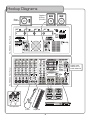
PA-PRO
-PRO 900
900W PROFESSIONAL P.A. MIXER
o
w
n
e
r
'
s
m
a
n
u
a
l
Table of Contents
Safety Instructions . . .
FCC Information . . . . .
Welcome. . . . . . . . . .
Listening for a Lifetime
Features . . . . . . . . . .
Hookup Diagrams . . . .
Rear Panel Features . .
Front Panel Features. .
Optional Accessories . .
Technical Specifications
Notes . . . . . . . . . . . .
Troubleshooting . . . . .
.
.
.
.
.
.
.
.
.
.
.
.
.
.
.
.
.
.
.
.
.
.
.
.
.
.
.
.
.
.
.
.
.
.
.
.
.
.
.
.
.
.
.
.
.
.
.
.
.
.
.
.
.
.
.
.
.
.
.
.
.
.
.
.
.
.
.
.
.
.
.
.
.
.
.
.
.
.
.
.
.
.
.
.
.... 3
.... 4
.... 5
.... 6
.... 7
. . 8-13
. . . 14
. 15-22
. 23-25
. 26-29
. . . 30
. . . 31
Safety Instructions
8. Ventilation - The appliance should be situated so its
location does not interfere with its proper ventilation.
For example, the appliance should not be situated on a
bed, sofa, rug, or similar surface that may block the
ventilation slots.
CAUTION
RISK OF SHOCK
CAUTION: To reduce the risk of electric
shock, do not remove cover (or back). No
user-serviceable parts inside. Only refer
servicing to qualified service personnel.
9. Heat - The appliance should be situated away from
heat sources such as radiators, heat registers,
stoves, or other appliances (including amplifiers)
that produce heat.
10. Power Sources - The appliance should be
connected to a power supply only of the type
described in the operating instructions or as marked
on the appliance.
Explanation of Graphical Symbols
The lightning flash & arrowhead
symbol, within an equilateral triangle,
is intended to alert you to the
presence of danger.
11. Grounding or Polarization - Precautions should be
taken so that the grounding or polarization means of
an appliance is not defeated.
The exclamation point within an
equilateral triangle is intended to alert
you to the presence of important
operating and servicing instructions.
12. Power-Cord Protection - Power-supply cords
should be routed so that they are not likely to be
walked on or pinched by items placed upon or
against them, paying particular attention to cords at
plugs, convenience receptacles, and the point where
they exit from the appliance.
WARNING
13. Cleaning - Unplug this unit from the wall outlet
before cleaning. Do not use liquid cleaners or
aerosol cleaners. Use a damp cloth for cleaning.
To reduce the risk of fire or electric shock, do
not expose this unit to rain or moisture.
14. Power lines - An outdoor antenna should be
located away from power lines.
1. Read Instructions - All the safety and operating
instructions should be read before the appliance is
operated.
15. Nonuse Periods - The power cord of the appliance
should be unplugged from the outlet when left unused
for a long period of time.
2. Retain Instructions - The safety and operating
instructions should be retained for future reference.
16. Object and Liquid Entry - Care should be taken so
that objects do not fall and liquids are not spilled into
the enclosure through openings.
3. Heed Warnings - All warnings on the appliance and in
the operating instructions should be adhered to.
17. Damage Requiring Service - The appliance should
be serviced by qualified service personnel when:
4. Follow Instructions - All operating and use
instructions should be followed.
A.
B.
C.
D.
The power supply cord or plug has been damaged; or
Objects have fallen into the appliance; or
The appliance has been exposed to rain; or
The appliance does not appear to operate normally
or exhibits a marked change in performance; or
E. The appliance has been dropped, or the enclosure
damaged.
5. Attachments - Do not use attachments not
recommended by the product manufacturer as they
may cause hazards.
6. Water and Moisture - Do not use this unit near water.
For example, near a bathtub or in a wet basement and
the like.
18. Servicing - The user should not attempt to service
the appliance beyond that described in the operating
instructions. All other servicing should be referred to
qualified service personnel.
7. Carts and Stands - The appliance should be used
only with a cart or stand that is recommended by the
manufacturer.
Note:
To CATV system installer's (U.S.A.): This reminder is
provided to call the CATV system installer's attention to
Article 820-40 of the NEC that provides guidelines for
proper grounding and, in particular, specifies that the
cable ground shall be connected as close to the point of
cable entry as practical.
7 A. An appliance and cart combination
should be moved with care. Quick stops,
excessive force, and uneven surfaces may
cause an overturn.
3
FCC Information
�� �������������������������������������
�������This product, when installed as indicated in the
instructions contained in this manual, meets FCC
requirements. Modifications not expressly approved by
Vocopro may void your authority, granted by the FCC,
to use this product.
������������� When connecting this product to
accessories and/or another product use only high
quality shielded cables. Cable(s) supplied with this
product MUST be used. Follow all installation
instructions. Failure to follow instructions could void your
FCC authorization to use this product in the U.S.A.
�������� This product has been tested and found to
comply with the requirements listed in FCC Regulations,
Part 15 for Class "B" digital devices. Compliance with
these requirements provides a reasonable level of
assurances that your use of this product in a residential
environment will not result in harmful interference with
other electronic devices. This equipment
generates/uses radio frequencies and, if not installed
and used according to the instructions found in the
owner's manual, may cause interference harmful to the
operation of other electronic devices. Compliance with
FCC regulations does not guarantee that interference
will not occur in all installations. If this product is found
to be the source of interference, which can be
determined by turning the unit "Off" and "On", please try
to eliminate the problem by using one of the following
measures:
Relocate either this product or the device that is being
affected by the interference.
Use power outlets that are on different branch (circuit
breaker or fuse) circuits or install AC line filter(s).
In the case of radio or TV interference, relocate/reorient
the antenna. If the antenna lead-in is 300-ohm ribbon
lead, change the lead-in to coaxial type cable.
If these corrective measures do not produce satisfactory
results, please contact your local retailer authorized to
distribute Vocopro products. If you can not locate the
appropriate retailer, please contact Vocopro, 1728
Curtiss Court, La Verne, CA 91750.
�������
The apparatus is not disconnected from the AC power
source so long as it is connected to the wall outlet,
even if the apparatus itself is turned off. To fully ensure
that the apparatus is indeed fully void of residual power,
leave unit disconnected from the AC outlet for at least
fifteen seconds.
���������
������������������������������������
�� To ensure the finest performance, please read this
manual carefully. Keep it in a safe place for future
reference.
�� Install your unit in a cool, dry, clean place - away from
windows, heat sources, and too much vibration, dust,
moisture or cold. Avoid sources of hum (transformers,
motors). To prevent fire or electrical shock, do not
expose to rain and water.
�� Do not operate the unit upside-down.
�� Never open the cabinet. If a foreign object drops into
the set, contact your dealer.
�� Place the unit in a location with adequate air
circulation. Do not interfere with its proper ventilation;
this will cause the internal temperature to rise and may
result in a failure.
�� Do not use force on switches, knobs or cords. When
moving the unit, first turn the unit off. Then gently
disconnect the power plug and the cords connecting to
other equipment. Never pull the cord itself.
�� Do not attempt to clean the unit with chemical solvents:
this might damage the finish. Use a clean, dry cloth.
�� Be sure to read the "Troubleshooting" section on
common operating errors before concluding that your
unit is faulty.
�� This unit consumes a fair amount of power even when
the power switch is turned off. We recommend that you
unplug the power cord from the wall outlet if the unit is
not going to be used for a long time. This will save
electricity and help prevent fire hazards. To disconnect
the cord, pull it out by grasping the plug. Never pull the
cord itself.
��� To prevent lightning damage, pull out the power cord
and remove the antenna cable during an electrical
storm.
��� The general digital signals may interfere with other
equipment such as tuners or receivers. Move the
system farther away from such equipment if
interference is observed.
�����
Please�check the copyright laws in your country
before recording from records, compact discs,
radio, etc. Recording of copyrighted material may
infringe copyright laws.
�������������������������������������
Be sure to position the voltage selector to match the
voltage of your local power lines before installing the
unit.
110V
4
Welcome
And thank you for purchasing the PA-PRO 900 from VocoPro, your ultimate choice in
vocal entertainment! With years of experience in the music entertainment business,
VocoPro is a leading manufacturer of vocal equipment, and has been providing patrons
of bars, churches, schools, clubs and individual consumers the opportunity to sound like
a star with full-scale club models, in-home systems and mobile units. All our products
offer solid performance and sound reliability, and to reinforce our commitment to
customer satisfaction, we have customer service and technical support professionals
ready to assist you with your needs. We have provided some contact information for
you below.
VocoPro
1728 Curtiss Court
La Verne, CA 91750
Toll Free: 800-678-5348
TEL: 909-593-8893
FAX: 909-593-8890
VocoPro Company Email Directory
Customer Service & General Information
[email protected]
Tech Support
[email protected]
Remember Our Website
Be sure to visit the VocoPro website www.vocopro.com for the latest information on
new products, packages and promos. And while you're there don't forget to check out
our Club VocoPro for Karaoke news and events, chat rooms, club directories and even
a KJ Service directory!
We look forward to hearing you sound like a PRO, with VocoPro, the singer’s ultimate
choice.
FOR YOUR RECORDS
Please record the model number and serial number below, for easy reference, in case of loss or theft. These
numbers are located on the rear panel of the unit. Space is also provided for other relevant information
Model Number
Serial Number
Date of Purchase
Place of Purchase
5
Listening for a Lifetime
Selecting fine audio equipment such as the unit youʼve just purchased is only the start of your
musical enjoyment. Now itʼs time to consider how you can maximize the fun and excitement your
equipment offers. VocoPro and the Electronic Industries Associationʼs Consumer Electronics
Group want you to get the most out of your equipment by playing it at a safe level. One that lets
the sound come through loud and clear without annoying blaring or distortion and, most
importantly, without affecting your sensitive hearing.
Sound can be deceiving. Over time your hearing “comfort level” adapts to a higher volume of
sound. So what sounds “normal” can actually be loud and harmful to your hearing. Guard
against this by setting your equipment at a safe level BEFORE your hearing adapts.
To establish a safe level:
• Start your volume control at a low setting.
• Slowly increase the sound until you can hear it comfortably and clearly, and without
distortion.
Once you have established a comfortable sound level:
• Set the dial and leave it there.
• Pay attention to the different levels in various recordings.
Taking a minute to do this now will help to prevent hearing damage or loss in the future. After all,
we want you listening for a lifetime.
Used wisely, your new sound equipment will provide a lifetime of fun and enjoyment. Since
hearing damage from loud noise is often undetectable until it is too late, this manufacturer and
the Electronic Industries Associationʼs Consumer Electronics Group recommend you avoid
prolonged exposure to excessive noise. This list of sound levels is included for your protection.
Some common decibel ranges:
Level
30
40
50
60
70
80
Example
Quiet library, Soft whispers
Living room, Refrigerator, Bedroom away from traffic
Light traffic, Normal Conversation
Air Conditioner at 20 ft., Sewing machine
Vacuum cleaner, Hair dryer, Noisy Restaurant
Average city traffic, Garbage disposals, Alarm clock at 2 ft.
The following noises can be dangerous under constant exposure:
Level
90
100
120
140
180
Example
Subway, Motorcycle, Truck traffic, Lawn Mower
Garbage truck, Chainsaw, Pneumatics drill
Rock band concert in front of speakers
Gunshot blast, Jet plane
Rocket launching pad
-Information courtesy of the Deafness Research Foundation
6
Features
Features
• 450W + 450W RMS Power Output (4 ohms)
• 8 Channels (4 Mic/Line, 4 Stereo/Line)
• Mic/Line Channel Inputs: ¼”, XLR
• Stereo/Line Channel Inputs: 1/8”, L/R RCA, L/R ¼”
• Independent Tone, Level and Effect Controls on All Input Channels
• DSP Reverb, Echo and Hiss Filter Effects with On/Off Switch
• Built-in Compressor for Microphone Channels
• L/R ¼” Effect Loop Jacks for Stereo Channels
• Dual 7-band Graphic EQs for Main and Monitor Output
• +48V Phantom Power
• 4 UHF Wireless Mic Module Ports*
• SDR-3 Digital SD Recorder Expansion Port*
• Balanced XLR L/R Main Output Jacks
• RCA L/R Record Out Jacks
• Subwoofer Output with 125Hz LPF and On/Off Switch
• Speakon and 1/4” Speaker Output Jacks
• Headphone Output with Source Select
*SDR-3 Digital SD Recorder and UHF Wireless Mics and Modules are Optional Accessories
7
Hookup Diagrams
��������
������
����������
���������������������
�����
�������
����������������������
���������
��������������
������������
����������������
��������������
�����������
������
��������
8
Hookup Diagrams
House of Worship/Full Band
For this example, there are four microphones connected to
channels 1-4. These microphones can either be the optional
UHF wireless channels, low-impedance corded microphones,
or high-impedance corded microphones. Musical
instruments are connected to channels 5-8. Note that when
connecting instruments to channels 5-8, the LEVEL control
will need to be set rather high due to the lower signal level
from instrument output. It is preferable to use channels 1-4
for instruments if you are using less than four microphones.
If there is a need to connect a laptop or other stereo music
source, you can connect to the designated stereo inputs on
channels 5/6-7/8.
For power output in this example, the PA-PRO 900 is
configured for MAIN L/R+MONITOR output. A pair of
passive speakers is powered via the MAIN L./R speaker
connector. A passive monitor speaker is powered via the
MONITOR speaker connector. An additional set of powered
speakers can be connected to the MAIN OUT jacks on the
front panel.
Recording can be done either with an optional SDR-3 SD
recorder (optional accessory), or to an external recording
device connected to the RCA record out jacks on the front
panel.
NOTES:
UHF wireless mic channels require the SOURCE SELECT
switch to be set to UHF.
POWER AMP ASSIGN switch must be best to MAIN L/
R+MONITOR
9
Hookup Diagrams
���������������������
��������
������
��
������
����������������������
���������
��������������
���������
��������������
����������������
�����
�����������
�����������������������
��������������������
10
���������
Hookup Diagrams
DJ
For this example we have two microphones in use on
channels 1 and 2; one for the DJ, the other as a backup
or guest speaker. There is a line-out from a DJ mixer
connected to CH. 5/6 to serve as the main music source.
For additional music needs, either a laptop computer or
MP3 player is connected to CH. 7/8.
You can have a sonic enhancer or other effect device
connected to the CH. 5/6 effect loops to apply desired
effects to the source music. Of, course you could have a
second effect device connected to CH. 7/8 effect loops
jacks as well. Note that, you will need special insert cables
in order to make these connections.
For output needs, you can configure the PA-PRO 900 for
standard two-channel stereo output with the POWER AMP
ASSIGN button. A set of passive speakers are connected
the speaker-level connectors on the rear panel. You can
have a set of powered speakers connected to the XLR MAIN
OUT jacks on the front panel for additional power. We also
have a powered subwoofer connected to the ¼” subwoofer
output on the front panel for that extra low end punch. Note
that when a subwoofer is connected, the SUBWOOFER(LPF)
toggle button should be set to ON.
NOTES:
UHF wireless mic channels require the SOURCE SELECT
switch to be set to UHF.
Low-impedance microphones require the MIC PAD switches
to be set to ON.
POWER AMP ASSIGN switch must be best to MAIN L,R
The SUBWOOFER button must be set to SUB.
Karaoke
For this setup you could have four microphones in use on
channels 1-4. There is a line-out from a karaoke player,
instead of a mixer, connected to CH. 5/6 to serve as the
main music source. For additional music needs, either a
laptop computer or MP3 player is connected to CH. 7/8.
You can have a digital key controller connected to the CH.
5/6 effect loops to apply desired effects to the source
music. Of course, you could have a second effect device
connected to CH. 7/8 effect loops jacks as well. Note that,
you will need special insert cables in order to make these
connections.
For output needs, you can have the PA-PRO 900 configured
for standard two-channel stereo output via the POWER AMP
ASSIGN button. A set of passive speakers are connected
the speaker-level connectors on the rear panel. You can
have a set of powered speakers connected to the XLR MAIN
OUT jacks on the front panel for additional power. For stage
monitoring, we have a powered stage monitor connected to
the ¼” MONITOR jack on the front panel. We also have a
powered subwoofer connected to the ¼” subwoofer output
on the front panel for that extra low end punch. Note that
when a subwoofer is connected, the SUBWOOFER(LPF)
toggle button should be set to ON.
NOTES:
UHF wireless mic channels require the SOURCE SELECT
switch to be set to UHF.
Low-impedance microphones require the MIC PAD switches
to be set to ON.
POWER AMP ASSIGN switch must be best to MAIN L,R
The SUBWOOFER(LPF) button must be set to ON/SUB.
11
Hookup Diagrams
���������������������
��������
������
��
������
����������������������
���������
��������������
���������
�����������
��������������������
12
Hookup Diagrams
Public Address/Presentation
For this set up, there are four microphones connected to
channels 1-4. These microphones can be either the optional
UHF wireless channels, low-impedance corded microphones,
or high-impedance corded microphones. Source music
devices are connected to channels 5-8. Note that when
connecting stereo source music devices to either CH. 5/6
or CH. 7/8, you can either connect via 1/8” mini-jack,
RCA or L/R ¼”. If connecting mono source audio devices,
connect them the CH. 5-8 via the ¼” jacks. Note that CH.
5/6 and 7/8 will be controlled together by the channel
strips. If connecting a single mono signal to either CH. 5/6
or CH. 7/8, connect to the L(MONO) jack.
For power output, this example shows PA-PRO 900
configured for MAIN L/R+MONITOR output. A pair of
passive speakers is powered by the MAIN L./R speaker
connector. A passive monitor speaker is powered by the
MONITOR speaker connector. An additional set of powered
speakers can be connected to the MAIN OUT jacks on the
front panel.
Recording can be done either with an optional SDR-3 SD
recorder, or to an external recording device connected to
the RCA record out jacks on the front panel.
NOTES:
If connecting a single mono signal to either CH. 5/6 or CH.
7/8, connect to the L(MONO) jack.
The optional UHF wireless mic channels require the SOURCE
SELECT switch to be set to UHF.
POWER AMP ASSIGN switch must be best to MAIN L/
R+MONITOR
13
Rear Panel Features
�
�
�
�
�
�
�
�
��
�
��
�
�
�
REAR PANEL FEATURES
1. POWER CONNECTOR – Connect the supplied 3-prong
power cord to this connector.
1a. NOTE: Before plugging in to a power receptacle, make
sure that voltage of your PA-PRO 900 is the same voltage
as your local AC mains voltage. The PA-PRO 900 power
input setting is factory set.
2. FUSE HOUSING – Houses the fuse. To remove the fuse,
unscrew the fuse cap counter-clockwise. In the case of a
blown fuse, replace once only. If the fuse blows a second
time, do not attempt to replace fuse again. If a fuse blows
repeatedly, there may be damage an internal component.
Further attempts to power on the unit can cause more
damage. In this case, refer to an authorized service center
for troubleshooting
5. SPEAKER CONNECTORS – These jacks provide speakerlevel output power from the internal power amplifier to
connected passive speakers. There are two types of
connector available: speakon and ¼” TS.
Speakon outputs are wired PIN 1+positive (hot), and PIN
2-negative (cold).
¼” TS outputs are wires TIP +positive, and SLEEVE
–negative.
The speaker-level output can be configured one of two ways
via the POWER AMP ASSIGN switch on the front panel:
MAIN L/R – This configuration is for standard MAIN
stereo L/R output. The left speaker output is the MAIN L
signal, and the right speaker output is the MAIN R signal.
Use this configuration to power two passive main speakers
for straight stereo output.
2a. NOTE: Only replace with the same type and rating of
fuse as marked.
MAIN L/R+MONITOR – This configuration outputs the
MAIN L/R channels as a mono signal to the LEFT (MAIN)
jacks, and the MONITOR channel as a mono signal to the
RIGHT (MON) jacks. Use this configuration to power a
passive PA/MAIN speaker on the left side and a passive
stage monitor on the right side.
3. WIRELESS MODULE EXPANSION PORTS – Install
optional UHF wireless modules in these ports. For details
on operating UHF wireless channels, please refer to the
optional accessories section. (page 23)
To
1.
2.
3.
4.
install an optional module:
Unscrew the two retaining screws.
Remove cover plate and store it in a safe place.
Fully insert UHF wireless module.
Replace and tighten screws.
4. WIRELESS ANTENNA CONNECTORS – When the
optional wireless modules are installed, connect the
antennas here for UHF wireless reception.
NOTE: If you are going to use one speaker per channel,
ensure the speakers’ impedance is no lower than 4 ohms. If
you are going to connect two speakers per channel, ensure
the speakers’ impedance in no lower than 8 ohms. These
two types of connectors are wired in parallel, therefore they
are able to be used together.
14
Front Panel Features
3. DSP/REV AUX – These controls adjust the amount of
DSP effects applied individually to channels 1-8. This allows
you to set more DSP effects to the microphone channels,
and less to channels with instruments connected. These
controls only adjust the amount of DSP applied to each
channel; to set the individual parameters of the DSP effects,
refer to the DSP REV CONTROL panel control.
�
��
A secondary function of this control is to adjust the
presence of that channel’s signal in the ¼” AUX output mix.
As the control is turned clockwise, the signal is increased.
As the control is turned counter-clockwise, the signal is
decreased.
�
�
4. HIGH – These controls adjust the amount of high
frequency in the audio signal for each channel. Increase the
HIGH control to add sparkle to vocals and instruments, but
keep in mind that excessive high frequency equalization can
lead to feedback. Decrease the HIGH control to reduce vocal
sibilance, reduce tape hiss, or “bacon crackle” from vinyl
recordings.
�
�
5. MED – These controls adjust the amount of midrange
frequency in the audio signal for each channel. Midrange is
the most commonly adjusted range in audio. Pianos, guitars
and the human voice can be dramatically adjusted sonically
by adjusting the midrange. For vocals a slight boost in the
midrange provides a good sound when playing through wellbalanced set of speakers.
�
�
�
�
CHANNEL STRIPS
The six vertical channel strips contain all the individual
controls for each channel. Each channel strip works
independently of each other, and adjusts only the signal
plugged into the jacks below it.
Note: If the optional wireless modules are installed, CH
1-4 control strips can adjust the signal from the wireless
microphones as well.
��
1. LEVEL – These controls adjust the amount of gain
for each channel available to the MAIN output. Adjust
these controls to achieve a good mix between connected
microphones/instruments. These controls do not adjust the
amount of gain available for the MONITOR output.
2. MON – These controls adjust the amount of gain for
each channel available to the MONITOR output. Since the
monitor output will typically be used for onstage reference,
set the individual levels to achieve a perfect monitoring mix.
These controls do not adjust the amount of gain available for
the MAIN output.
6. LOW – These controls adjust the amount of low
frequency in the audio signal for each channel. Low
frequency adjustments are made to add serious thump
to kick drums, fatten up bass lines, or add a “full” sound
to instruments and vocalists. You can also decrease low
frequency to save your speakers from blowing during
playback of audio with a heavy bass presence.
��
��
7. SOURCE SELECT – These buttons toggle the source
input for channels 1-4. If using an optional UHF wireless
expansion module, select UHF. If you are connecting a
microphone or line instrument to the front panel via the ¼”
or XLR jacks, set the switch to WIRE.
8. MIC PAD 30dB – These switches can provide a 30dB
signal cut for high level input sources. The MIC PAD is
designed to prevent overloading a channel with a high-level
signal. If the switch is set incorrectly, excessively distorted
audio can result. If you are connecting a line-level input
source, such as a line out from a mixing device, set the
switch to ON. If you are connecting a microphone-level
signal, set the switch to OFF.
��
15
��
��
��
��
�
��
�
Front
Panel Features
�
��
�
��
�
��
PATCH BAY
MIC/LINE (CH 1-4)
The MIC/LINE inputs are for connecting microphones,
instruments, or line-level output signals. Once the devices
are connected, the signals can be customized using the
individual channel strips, and further controlled using the
DSP, EQ and main system controls. For each of the channels
1-4, it is important to note that if you connect a device to
BOTH the ¼” and XLR jacks simultaneously, turning one of
them off will turn them both off. This is due to how the jacks
are wired internally.
9. ¼” MIC/LINE INPUT – These jacks are for connecting
devices with microphone/line-level signals. Both balanced or
unbalanced ¼” cables are suitable for connecting to these
jacks. If you are connecting a microphone that requires
phantom power to these jacks, remember that you need
a balanced cable, and that you need to set the +48V
phantom power switch to ON. When connecting to these
jacks, remember to ensure that the MIC PAD and SOURCE
SELECT switches are set correctly. Refer to above text for
details on them.
10. XLR INPUT – These XLR jacks are for connecting
devices with balanced microphone/line-level signals. Use
balanced XLR cables for connecting to these jacks. If you
are connecting a microphone that requires phantom power
to these jacks, remember to set phantom power switch to
ON. When connecting to these jacks, remember to ensure
that the MIC PAD and SOURCE SELECT switches are set
correctly. Refer to above text for details on them.
��
��
that devices can be connected to all three sets of jacks
per channel simultaneously, however, there is no way to
individually mix the audio levels from each device. Effects can
be applied to the stereo channels using the ¼” INSERT jacks
(ST CH EFFECT LOOP).
11. MP3/LAPTOP – These 1/8” jacks are for connecting
source audio devices. The signal can be either mono or
stereo. If connecting a mono signal, use a 1/8” TS cable.
If connecting a stereo signal, use an 1/8” TRS cable.
Devices that have line-level outputs other than 1/8” can be
connected to these jacks using an appropriate adapter/
cable.
12. RCA L/R – These jacks are for connecting source
audio devices with line-level, unbalanced output, such as
CD+G player, iPod docks, tape decks etc. Devices that have
line-level outputs other than L/R RCA can be connected
to these jacks using an appropriate adapter/cable. Note
that you cannot directly connect phono-level outputs from a
turntable; a phono pre-amp is required.
13. ¼” L(MONO)/RIGHT – These ¼” jacks are for
connecting source audio devices with ¼” line-level output.
Use ¼” TS cables to make the connections. If you are
connecting stereo output, connect the L channel to the
L(MONO) jack, and connect the right channel to the RIGHT
jack. If you are connecting a single mono signal and only
require one connection, connect to the L(MONO) jack.
Connecting a single mono line to only the RIGHT jack will
result in no sound.
1/8”, RCA, 1/4” STEREO (CH 5-8)
These input jacks are for connecting devices with stereo
output. The 1/8” jack is labeled MP3/LAPTOP but can be
used to connect any line-level device with an 1/8” plug. L/R
RCA jacks provide connectivity for devices that utilize linelevel RCA output. The ¼” jacks can be connected in both a
stereo (in tandem) and mono (separate) configuration. Note
16
Front Panel Features
��
��
COMPRESSOR (CH.1-4)
Channels 1-4 have on-board compression available for
preventing unwanted distortion in the audio signal. The
compressor works by setting a threshold level with the
threshold knob. Once a signal level exceeds that threshold,
the signal is automatically compressed. Compression is very
useful when the mic/line signal is very dynamic (fluctuating
from very low to high levels) and has the potential to
overload the inputs. If you think there is chance of someone
screaming into the mic with a burst of enthusiasm, it would
be a good idea to apply some compression.
��
��
��
14. THRESHOLD KNOB – Use this knob to set the
threshold level for the compressor. When set to OFF, no
compression is applied. As the knob is turned counterclockwise, the threshold level drops, and increases the
amount of compression applied.
��
15. COMPRESSOR LEDs – These LEDs reflect the amount
of compression being applied.
��
��
��
��
��
DSP REV CONTROL
The on-board DSP effects are a great way to spice up your
vocals or instruments. The two main effects are echo and
reverb. The echo effect can be customized by adjusting
the echo repeat and echo delay controls. Reverb is ideal
for vocals as it adds a sense of spaciousness without echo
repetitions that could “muddy” the vocal signal.
��
��
��
��
16. ECHO LEVEL – This control adjusts the overall level of
the ECHO effect. Use this control to adjust the amount of
ECHO applied when adjusting the master effect level control.
To increase echo, turn the control clockwise. To decrease
echo, turn the control counter-clockwise.
��
��
��
��
17. ECHO REPEAT – This control is used to adjust the
number of repetitions in the echo effect. When set to a
minimum, there will be no repetition of audio. As this control
is turned clockwise, more echo repetitions will occur.
��
��
��
��
��
��
17
��
Front Panel Features
18. ECHO DELAY – This control is used to adjust the
length of time between each echo repetition. When set to
minimum, the echo repetitions will occur rapidly, with little to
no time between them. As this control is turned clockwise,
the time between each repetition will increase.
19. DSP ON/OFF – Use this control to quickly enable or
disable all DSP effects. This can be used to switch to a
“dry” signal for DJ or speaker announcements. When the
announcements are over, hit the button again to reapply
the effects. When the button is in the OUT position, all DSP
effects are off; when the button is in the IN position, all DSP
effects are on.
23. FOOT SW. – This input jack is for connecting an
external footswitch that can be used to enable or disable
DSP effects. The DSP ON/OFF button needs to be in the ON
position to use the footswitch. Any single-button footswitch
with a ¼” TRS plug can be connected and used.
24. ST CH EFFECT LOOPS
These ¼” insert jacks are for connecting external effects
devices such as digital key controllers, equalizers, and sonic
enhancers. With an insert jack, a signal can leave the jack
to an external processor, and return post-processed via the
same insert jack. A special insert cable is required, see
your effects processor manual to determine what type of
cable to use. Effect integration via the effect loop jacks is
only available to signals from CH-5-8. If a stereo device is
connected to CH. 5/6 or 7/8, you need to make an insert
connection for each channel (L/R). Note that the loop jacks
are sent before the signal hits the on-board EQs, so keep
that in mind if you are using the insert jacks to integrate an
external EQ.
��������������������������������������
����������
���������
��������������
�������������������������������
�
����������������������������������
20. REVERB LEVEL - This control adjusts the overall level
of the reverb effect. Use this control to adjust the amount
of REVERB applied when adjusting the master effect level
control. To increase reverb, turn the control clockwise. To
decrease reverb, turn the control counter-clockwise.
21. HISS FILTER – Thue control is used to reduce the
amount of sibilance in the vocals while using DSP echo with
repeat. As the control is turned clockwise, less sibilance will
occur during each echo repitition.
NOTE: This feature only works when DSP repeat is applied.
22. MASTER EFFECT LEVEL – This control is used to
adjust the overall level of all the effects combined. Use this
control after you have already made individual adjustments
to the reverb, echo and hiss filter controls. If you find that
you applied too much or too little DSP effects and need to
quickly make an adjustment to all the channels, use this
control.
Note: There are two other locations to adjust the amount
of DSP that goes into the mix: The DSP controls on the EQ
panel, and the DSP controls on the channel strips.
18
Front Panel Features
��
��
��
��
��
��
�
�
�
�
��
25. MAIN L, R GRAPHIC EQ – This 7-band graphic EQ
is used to customize the sound of the MAIN L, R mix
output. This EQ section affects the signals found in the
MAIN (XLR), headphone, line-level, and speaker-level jacks
(when configured to MAIN L, R). The 7 slide controls each
represent a frequency band: 125, 250, 500, 1K, 2K, 4K,
and 8K. Each of the slide controls adjusts the audio level of
its particular frequency with up to a 12dB boost or cut. If
left in the center position, there will be no change to audio
level the frequency. It is important to remember that EQ
controls are meant to provide precise adjustments to an
audio signal, and not overly inflate a signal resulting in an
unnatural sound. Human hearing can adapt quite quickly to
a particular sound signature, so it is best to find a suitable
setting and leave it there until a change in the source audio
or environment requires a change in the EQ.
28. DSP REV TO MAIN L, R – This control adjusts the
amount of DSP effects that is applied to the MAIN L, R mix.
This control is ideal for making quick on-the-fly adjustments
to the DSP effects level on the MAIN L, R mix which is
routed to the line-level outputs and speaker-level outputs.
When configuring your DSP effects, this control is used
after the MASTER EFFECT LEVEL control in the DSP controls
panel. Note that when the power amp assign is set to MAIN
L, R+MONITOR, this control will not adjust the DSP effects
of the MONITOR mix.
��
��
��
��
��
��
��
26. MAIN L, R LEDs – These stereo LEDs display the
output level of the MAIN L, R mix. The LEDs are marked
from –10dB to +6dB. It is important to monitor these LEDs
as they can prevent a distorted audio signal and possible
damage to your speakers. An optimal signal will be mostly
contained to the green LEDs (up to 0dB), with occasional
peaks into the first red LED (+3dB). If the mix reaches
+6dB, it is strongly advisable to reduce the MAIN L, R
LEVEL control.
��
27. MAIN L, R LEVEL – This control adjusts the signal level
of the MAIN L, R mix to be sent to the line-level outputs,
MAIN L, R LEDs, headphone and speaker-level outputs. This
control provides a one-touch adjustment to the MAIN L, R
mix, especially useful when the power amp assign is set to
MAIN L, R output. When the MAIN L, R LEDs enter the
+6dB range, use this control to make a quick adjustment.
When the power amp assign is set to MAIN L, R+MONITOR,
this control will only affect the mix sent to the MAIN (XLR),
AUX and (L) speaker-level output.
��
��
��
��
19
��
��
��
��
Front Panel Features
��
��
�
�
��
�
��
��
��
��
��
�
29. MONITOR GRAPHIC EQ – This 7-band graphic EQ is
used to customize the sound of the MONITOR mix output.
This EQ section affects the signals found in the MONITOR
(1/4”) jack and the speaker-level jack (when configured to
MAIN L, R+MONITOR). The 7 slide controls each represent
a frequency band: 125, 250, 500, 1K, 2K, 4K, and 8K.
Each of the slide controls adjusts the audio level of its
particular frequency with up to a 12dB boost or cut. If left
in the center position, there will be no change to audio
level the frequency. It is important to remember that EQ
controls are meant to provide precise adjustments to an
audio signal, and not overly inflate a signal resulting in an
unnatural sound. Human hearing can adapt quite quickly to
a particular sound signature, so it is best to find a suitable
setting and leave it there until a change in the source audio
or environment requires a change in the EQ.
��
��
��
��
��
30. MONITOR LEDs – These mono LEDs display the output
level of the MONITOR mix. The LEDs are marked from
–10dB to +6dB. It is important to monitor these LEDs as
they can prevent a bloated audio signal and possible damage
to your speakers. An optimal signal will be mostly contained
to the green LEDs (up to 0dB), with occasional peaks into
the first red LED (+3dB). If the mix reaches +6dB, it is
strongly advisable to reduce the MONITOR LEVEL control.
��
��
31. MONITOR LEVEL – This control adjusts the signal level
of the MONITOR mix to be sent to the line-level outputs,
MONITOR LEDs, and speaker-level output. This control
provides a one-touch adjustment to the MONITOR mix, when
the power amp assign is set to MAIN L,R+MONITOR output.
When the MONITOR LEDs enter the +6dB range, use this
control to make a quick adjustment.
32. DSP REV TO MONITOR – This control adjusts the
amount of DSP effects that is applied to the MONITOR mix.
This control is ideal for making quick on-the-fly adjustments
to the DSP effects level on the MONITOR mix, which is
routed to the line-level outputs and speaker-level output.
When configuring your DSP effects, this control is used
after the MASTER EFFECT LEVEL control in the DSP controls
panel.
20
��
��
Front Panel Features
34. POWER AMP ASSIGN – This switch lets you choose
which signals will be routed to the PA-PRO 900’s power
amplifier. This provides flexibility in how the PA-PRO 900’s
internal power amplifier can be utilized.
�
To set the POWER AMP ASSIGN switch, use a small
screwdriver to maneuver the switch to the desired position.
��
Set this switch to MAIN L,R for straight
stereo playback. When configured this
way, the LEFT channel will output to the L
speaker-level outs, and the RIGHT channel
will output to the R speaker-level outs.
Select MAIN L, R in situations when there
is no need to power a monitor speaker,
either because the monitor speaker is selfpowered, or there is no need for a monitor
speaker.
�
��
�
��
�
��
��
33. +48V PHANTOM POWER – This button toggles
phantom power to all the XLR microphone jacks. Enabling
phantom power sends low current DC voltage to a
microphone’s electronics through the same cable that
carries the audio signal.
��
��
��
Set this switch to MAIN L,R+MONITOR
when you need to power a monitor speaker.
In this configuration, the MAIN L,R mix is
output to the L speaker-level outs, and the
MONITOR mix is output to the R speakerlevel outs.
Most professional condenser microphones require phantom
power. There are some semi-pro microphones that use a
battery to provide the required voltage, and of course many
microphones that do not require phantom power at all. It
is wise to make sure that the microphone you are feeding
phantom power to actually requires it.
��
35. CH. 1-4 MUTE – This button is used to quickly mute all
audio from channels 1-4. This feature is very handy during
breaks and intermissions; audio can be disabled quickly
without having to adjust any other control. Push the button
IN to mute the audio, press the button again (OUT) to have
the audio return to the mix. When mute is activated, the
MUTE LED will remain lit until mute is disabled.
36. CH. 5-8 MUTE - This button is used to quickly mute all
audio from channels 5-8. This feature is very handy during
breaks and intermissions; audio can be disabled quickly
without having to adjust any other control. Push the button
IN to mute the audio, press the button again (OUT) to have
the audio return to the mix. When mute is activated, the
MUTE LED will remain lit until mute is disabled.
37. POWER – Use this switch to power the PA-PRO 900
ON/OFF.
NOTE: Before powering on, make sure that voltage of your
PA-PRO 900 is the same voltage as your local AC mains
voltage. The PA-PRO 900 is factory set for specific power
needs
NOTES: When phantom power is enabled, refrain from
connecting devices (including musical instruments) via
unbalanced ¼” cables; use balanced ¼” cables instead.
If you need to connect a microphone that is not phantom
powered, simply connect it via a balanced XLR cable.
21
��
��
Front Panel Features
��
��
��
��
��
Master Out Panel
The master out panel is where you make output connections
to external devices such as mixers, amplifiers, powered
speakers, headphones, recording devices, etc. All the
signals from these jacks are line-level, meaning that they
are not powered by the internal amplifier, and are suited for
connection to line-level inputs.
38. MAIN OUT – These stereo jacks route balanced
line-level signals of the MAIN mix to external devices. The
signals are identical to those sent to the speaker-level outs,
so any DSP effects and EQ will be present in the signals.
Use these jacks to connect to external amplifiers, mixers
or power speakers. Use balanced XLR cables to make the
connections.
39. MONITOR – This ¼” jack is used to route an
unbalanced line-level mono mix of the MAIN signal to an
external device such as a powered monitor speaker. The
signal is a mono mix of the main signal, and all DSP effects
and EQ will be present in the signal. Use an unbalanced
cable to make the connection.
��
��
42. MONO/SUBWOOFER – This ¼” jack can be used to
send a line-level signal suited for subwoofer connection,
or a mono signal of the main mix. When using this jack
to connect to a subwoofer, the signal will be filtered so
that all frequencies above 125Hz are blocked. To use as a
subwoofer, press the MONO/SUB button to the IN position.
To use this jack to route a mono signal of the main mix,
depress the MONO/SUB button to the OUT position.
43. HEADPHONE – This ¼” jack routes a line-level signal of
the main mix for connecting headphones or other device via
a ¼” TRS cable. To adjust the headphone out signal use the
MAIN L,R level control. DSP effect and EQ will be present in
the headphone out signal.
44. HEADPHONE ASSIGN – This switch lets you choose
which signals will be routed to the headphone out jack.
To set the HEADPHONE ASSIGN switch, use a pointed
device, such as a small screwdriver, to maneuver the switch
to the desired position.
Set this switch to MAIN L,R for straight stereo
playback.
40. AUX ¼” – This ¼” jack output is a mix of the channels
routed to the AUX channel. The presence of channels in
this mix will depend on the DSP REV/AUX control for each
channel. To increase or decrease a channel’s presence
in this mix, adjust the DSP REV/AUX control for that
channel. The AUX mix is “dry”, meaning DSP effects and
EQ are bypassed. Use this jack to send a dry mix to an
external effect device or secondary system. The AUX gain
knob above the jack will increase or reduce the level of this
output.
Set this switch to MAIN L,R+MONITOR to have
the MAIN L,R mixed to the L channel, and the
MONITOR mix to the R channel.
41. REC OUT – These stereo RCA jacks route unbalanced
line-level signals of the MAIN mix to external devices. The
record out mix will have DSP effects applied, but no EQ. Use
these jacks to connect to an external recording device, or
to amplifiers, mixers or power speakers. Use RCA cables
to make the connections. You can also use adapters if your
recording device has input jacks other than RCA.
22
Optional Accessories
�
�
�
�
�
�����
���������
����
����
���
��
���
��� ���� �����
��
�������������������
�
�
�
SDR-3 RECORDER (optional accessory)
Use the optional SDR-3 (if installed) to capture audio direct
to SD card. Once recorded, the audio can then be routed
to either CH 7-8 or the MAIN mix for immediate playback.
Of course, you can also remove the SD card and transfer
the MP3 files to your computer for further editing and
processing.
1. REC VOL CONTROL – Use this control to set the
recording gain level. Turn clockwise to increase the gain,
turn counter-clockwise to decrease the gain level. Use the
REC LEVEL LEDs to monitor the record level as you adjust
the REC VOL CONTROL. Note that the REC VOL CONTROL
does not control the volume level when playing back from
the SD card.
2. PLAY/STOP BUTTON – This dual function is used to
initiate playback of recorded material, and to stop playback,
or a recording, in progress.
When not in record mode, press the PLAY/STOP button to
start playback. Playback will commence from the last track
recorded.
During a recording, press the PLAY/STOP button to stop
the recording and conclude the track.
3. PREV BUTTON – This button will skip back through
previously recorded tracks. When the first track recorded
is reached, it will continue to skip back starting with the last
track recorded.
4. NEXT BUTTON – This button will skip forward through
previously recorded tracks. When the last track recorded
is reached, it will continue to skip forward from the first
recorded track.
�
��
5. REC BUTTON – This button is used to put the SDR-3 in
record mode, initiate recording, and pause a recording in
progress without creating a new track.
In stop mode, press the REC button once to place the SDR3 in record pause mode. This is the time to check the levels
of the audio to be recorded and adjust the REC VOL control
if necessary.
Press the REC button a second time to begin recording.
Pressing the REC button during a recording in progress will
pause the recording without creating a new track. This is
useful for recording several sections of a recording session
into a single cohesive track without breaking it up into
several tracks.
6. REC LED – This red LED indicates the recording status
of the SDR-3. When the SDR-3 is in record pause mode,
the REC LED will blink. When a recording is in progress, the
REC LED will be stay lit until the recording is completed, or
is set back to record pause mode.
7. PLAY LED – This orange LED will illuminate during
playback of recorded material, and during a recording in
progress.
8. POWER LED – This green LED indicates the SDR-3 is on
and drawing power from the PA-PRO 900. This LED should
illuminate and stay lit as long as the PA-PRO 900 is powered
on.
23
Optional Accessories
9. SD CARD SLOT – Insert your SD card into this slot. The
SDR-3 will not record without an SD card in this slot.
10. REC LEVEL LEDs – These LEDs visually represent the
gain level of the signal being recorded. There are five green
LEDs and two red LEDs. An optimal recording level will
illuminate all the green LEDs with minimal activity on the red
LEDs.
11. SD PLAYBACK ROUTE – This button will direct the
audio from the SD player to either the MAIN(L,R) output, or
to CH 7/8. Swtiching the playback to CH 7/8 will allow you
to make adjustments and/or add effects to the audio signal
using the CH 7/8 controls.
SDR-3 Installation
1. Unscrew the two retaining screws.
2. Remove plate and store it in a safe place.
3. Attach the cable to the back of the SDR-3.
4. Carefully slide the SDR-3 into place.
5. Replace and tighten screws.
Inserting/Removing an SD card
1. Insert SD card with the same alignment as indicated by
the SD card icon.
2. Push the SD card unit it clicks into place.
3. To remove the SD card, gently push in until it pops out
slightly; it is then safe to remove.
NOTE: The maximum size SD card that can be used by the
SDR-3 is 2GB. The SDR-3 does not support SDHC cards.
Recording to the SDR-3
Prior to recording to the SDR-3, you want to ensure that
the signal being recorded is properly mixed. Refer to the
text on “REC LEVEL LEDs” to ensure a good level. Once you
are happy with your overall mix, follow the steps below to
record.
In stop mode, press the REC button once to place the SDR3 in record pause mode. This is the time to check the levels
of the audio to be recorded and adjust the REC VOL control
if necessary.
Press the REC button a second time to begin recording.
Pressing the REC button during a recording in progress will
pause the recording without creating a new track. This is
useful for recording several sections of a recording session
into a single cohesive track without breaking it up into
several tracks.
24
Optional Accessories
�
�
�
�
�
UHF Wireless Channels (optional accessory)
You can add up to four UHF wireless microphone modules
(sold separately) to use with the PA-PRO 900. Each port on
the rear panel corresponds to a mic channel on the front
panel. Adjustments made to the channel strips on the front
panel will adjust the audio from the wireless microphones.
Channel 1 on the front panel is tied to Channel 1 on the
rear panel, Channel 2 to Channel 2 and so forth. Refer to
the information below to setup and use your UHF wireless
microphone(s).
Module Description and Functions
1. POWER (LED) - Indicates there is power to the module.
2. RF (LED) - Lights when an RF connection is made.
This LED should light when you turn on the associated
microphone. If this LED light when its associated
microphone is turned off, that indicates that another
external device is connected to that channel (interference).
3. AF (LED) - Lights when AF signals are being transmitted.
This LED will light as sounds is picked up and transmitted
from the associated microphone (speech or instrument).
4. SQ (Squelch) - The Squelch control is used to mute
unwanted noise interference from a microphone channel
when the associated transmitter is turned off. To adjust
squelch to clockwise to increase squelch, and counterclockwise to decrease squelch.
NOTE: Typically, as a channel’s squelch setting increases, its
operating range decreases. It is therefore recommended to
set the squelch control only as high as necessary to mute
any noise interference.
Setting Up
For each UHF wireless channel, you will have a handheld
microphone, wireless module, and antenna. Follow the steps
below to set them up.
Module Installation
1. Unscrew the two retaining screws.
2. Remove the cover plate and store it in a safe place.
3. Fully insert the wireless module so the module is flush
with the faceplate of the PA-PRO 900.
4. Replace and tighten screws.
Removing Modules
1. Unscrew the two retaining screws.
2. To remove, simply slide the module out of the
compartment.
3. Align the cover plate, and tighten screws.
Antenna Installation
Insert the antenna’s TNC connector into the corresponding
channel’s TNC antenna jack and twist clockwise until it is
firmly connected.
If installing multiple antennas, ensure the antennas are not
touching each other.
Microphone Battery Installation
1. To remove the lid, press down on the tab and slide the lid
down towards the bottom of the mic.
2. Insert 2 fresh 1.5-volt AA alkaline batteries. Make sure
the batteries are inserted in the right direction according
to polarity (+/-).
3. Close the battery compartment lid.
Basic Operations
1. Press the POWER switch on the front panel of the PAPRO 900.
2. Adjust the module level controls to approximately 50%.
3. Switch the microphone’s power switch to the ON position.
2. Set the channel strip source select button to UHF (front
panel).
4. Talk or sing into the microphones and adjust the channel
strip level and eq controls (front panel) until you are
satisfied with the sound.
Note: During normal operation, the RF/AF signal LED’s will
illuminate when a microphone is being used.
5. Level - This knob controls the microphone volume (gain)
level for this channel. Turn clockwise to increase volume,
and counter-clockwise to decrease.
25
Technical Specifications
PA-PRO 900 SPECIFICATIONS
Mixer Input
Specification
(AT MAIN L/R OUTPUT +4dBu,1kHz)
INPUT
CONNECTION
LEVEL(RATED INPUT)
TOTAL GAIN
IMPEDANCE
MIC INPUT
XLR (BAL)
-50dBu
54dB
1 Kohm
CH1-CH4
1/4” TRS (BAL/UNBAL)
-20dB(PAD ON)
24dB
MUSIC
LINE 1/4”TRS(UNBAL)
-22dBu
26dB
2.8Kohm
CH5/6-7/8
CD RCA STEREO (UNBAL)
-22dBu
26dB
2.8Kohm
MP3 1/8” PHONE(UNBAL)
-24dBu
28dB
1.8Kohm
0dBu
4dB
10Kohm
TIP:L,RING:R
ST EFFECT LOOP
1/4”(UNBAL)
TIP SEND/RING RETURN
UHF MODULE
30PIN CARD EDGE
-34dBu
38dB
1Kohm
SD CARD MODULE
6PIN WIRE CONNECT
-24dBu
28dB
1.8Kohm
CONDITION : LEVEL VR MAX, EFFECT MASTER MIN, MAIN VR MAX, ALL EQ CENTER
Mixer Output Specification
OUTPUT
MAIN MIX OUTPUT L/R
CONNECTION
LEVEL
IMPEDANCE
XLR (BALANCED)
+4dBu
240ohm
MONITOR OUTPUT
1/4” TRS PHONE(UNBAL)
+4dBu
120ohm
AUX OUTPUT
1/4” TRS PHONE (UNBAL)
+4dBu
120ohm
MONO/SUB WOOFER
1/4” TRS PHONE(UNBAL)
+4dBu
120ohm
1/4” PHONE
1.0V
33 ohm
-6dBu
120ohm
CONNECTION
OUTPUT
LOAD
T.H.D
SPEAKON / 1/4”TS
2x500W(PEAK)
4ohm
3%
2x450W(AVG)
4ohm
1%
2x435W(RATED)
4ohm
0.10%
2x228W(AVG)
8ohm
1%
2x210W(RATED)
8ohm
0.10%
(SUB WOOFER 75Hz/-3dB)
HEAD PHONE OUTPUT
(TIP: LEFT,RING:RIGHT)
REC OUT
RCA STEREO
Loudspeaker Output
AT 4ohm LOAD
SPEAKER OUTPUT TERMINAL
26
Technical Specifications
Frequency Response
(AT MAIN L/R OUTPUT +4dBu)
MIC INPUT /CH1-4
10Hz-24kHz
0dB / -1.5dB
STEREO INPUT/ CH5-8
10Hz-35kHz
0dB / -1.5dB
100Hz
±15dB
MID
2.5kHz
±12dB
LOW
10kHz
±15dB
MAIN L/R OUTPUT (XLR/BAL)
125Hz
±12dB
MONITOR OUTPUT (1/4”
PHONE)
250Hz
±12dB
500Hz
±12dB
1kHz
±12dB
2kHz
±12dB
4kHz
±12dB
8kHz
±12dB
LEVEL
T.H.D
Channel EQ
CH1-8 EQ HIGH
7-Band Graphic EQ
T.H.D+N
(1KHz,30K
BANDWIDTH)
OUTPUT
MIC MONO TO SPEAKER
OUTPUT
42V
Less Than 0.07%
42V
Less Than 0.06%
CH1-4 to MAIN MIX OUTPUT
L/R
+4dBu(balance)
Less Than 0.07%
CH5-8 TO MAIN MIX OUT L/R
+0dBu(UNBAL)
Less Than 0.05%
STEREO EFECT LOOP SEND
0dBu(1/4” UNBAL)
Less Than 0.01%
-6dBu(RCA STEREO)
Less Than 0.05%
+4dBu(UNBAL)
Less Than 0.05%
+2dBu(1/4” UNBAL)
Less Than 0.05%
L/R
CH5-8 TO SPEAKER OUTPUT
L/R
REC OUT L/R
CH5-8 TO MAIN MONO OUT
CH5-8 to Woofer OUT
@50Hz LPF ON
Less Than 0.05%
27
Technical Specifications
Hum & Noise(S/N)
OUTPUT
AMP OUTOUT
LEVEL
< -80 dB
1/2POWER 1kHz
LEFT/RIGHT
MIC TO MAIN MIX OUTPUT
CONDITION
STEREO LOOP RETURN IN
< -74 dB
MIC LEVEL CENTER, MAIN VR +4dB ADJ
L/R
EQ CENTER, INPUT -30dB
AUX/MONITOR OUTPUT
< -73 dB
MONO OUTPUT
< -73 dB
MONITOR/AUX MASTER +4dB ADJ
ST CH -10dB, LEVEL CENTER, EQ CENTER
MONITOR/AUX MASTER +4dB ADJ
ST CH -10dB, LEVEL CENTER ,EQ CENTER
REC OUT L/R
< -72 dB
ST EFECT LOOF OUTPUT
< -74 dB
STEREO CH L/MONO INPUT-10dB
MAIN VR +4dB ADJ
STEREO ONLY LEVEL MAX, ALL VR MIN
SEND (TIP)
HEAD PHONE OUTPUT
EQ CENTER
< -70 dB
STEREO CH L/MONO INPUT-10dB
CH LEVEL CENTER, EQ CENTER
E.I.N
MIC INPUT
-127dBu
150ohm TERMINATION
Compress Limit
COMPRESSOR
MIN 0 dB THROUGH MAX 24dB RANGE (OFF POSITION)
THRESHOLD LIMIT
Crosstalk(1kHz)
MONO CHANNELS
STEREO CHANNELS L/R
CH1/2,2/3,3/4
MAIN L XLR (BAL)
-70dB
MAIN LEFTt
MAIN R XLR (BAL)
-70dB
MAIN RIGHT
MAIN L XLR (BAL)
-70dB
CH1-4 TO MAIN L/R
CH LEVEL DOWN
-70dB
MAIN LEVEL DOWN
-80dB
Attenuation
INPUT & OUTPUT
STEREO CH5-8 TO MAIN L/R CH LEVEL DOWN
MAIN LEVEL DOWN
28
-75dB
-80dB
Technical Specifications
Maximum Input Level
INPUT
CONNECTION
LEVEL
MIC INPUT
XLR (BAL)
-20dBu
CH1-CH4
1/4” TRS (BAL/UNBAL)
+10dB(PAD ON)
STEREO
LINE 1/4”TRS(UNBAL)
-0dBu
CH5/6-7/8
CD RCA STEREO(UNBAL)
-0dBu
MP3 1/8” PHONE(UNBAL)
-2dBu
TIP:L,RING:R
EFFECT Controls
(D.S.P)
REVERB/DELAY CONTROL
ECHO DELAY
40mS-242mS
ECHO REPEAT
30%-80%
ECHO VOLUME
0%-100%
REVERB VOLUME
0%-100%
HISS FILTER
3kHz-8kHz
EFFECT MASTER
0%-100%
EFX DSP CONTROL
EFX DSP BUS CONTROL
FOOT SWITCH (1/4” TS), ON/OFF SWITCH with LED INDICATOR
EFX TO MAIN/MONITOR
CONTROL
POWER AMP ASSIGN,
HEADPHONE ASSIGN
MONO, STEREO CH MUTE
L+R,MONITOR / LEFT, RIGHT
EACH SWITCH, INDICATOR
POWER
CONSUMPTION
AC 120V , 13 A (@ RATED POWER)
DIMENSION(WXHXD)
UNIT
INNER BOX
SHIPPING BOX
468X254X409 mm
18.4X10X16.1 in
550X330X370 mm
21.6X13X14.6 in
560X340X380 mm
22X13.4X14.9 in
WEIGHT
NET: 20.5 kg, 45.2 lbs
SHIPPING: 21.6 kg, 47.6 lbs
29
Notes
30
Troubleshooting
There is no power
• Make sure the power adapter cord is firmly connected to the back of the unit and to the power outlet.
• If using a power strip/surge-protector, make sure that it is plugged in and switched on.
• Check the fuse, and replace if blown. If the fuse blows again immediately, do not replace it again. Instead, contact
VocoPro technical support.
There is no sound
•
•
•
•
•
•
•
•
Make sure everything is connected firmly and properly.
Make sure there are no defective cables.
Make sure all of your components are turned on.
Make sure all of the components (mixer, player, etc.) are set to the proper inputs.
Make sure mic channels 1-4 are set to the correct input using the SOURCE SELECT buttons.
Make sure CH 1-4 and CH 5-8 MUTE buttons on the front panel are turned off.
Make sure the volume is turned up on the EQ panels and the input channel strips.
If an external effects device is connected, make sure it is powered on.
The sound is only coming from one speaker
• Make sure there are no defective cables, and that the cables are connected properly.
• Make sure the POWER AMP ASSIGN switch on the front panel is set to MAIN(L,R).
The sound is cuts out, is unclear, or has static
• Make sure everything is connected firmly and properly.
• Make sure there are no defective cables.
The microphone audio volume drops or cuts out suddenly
•
•
•
•
If using an optional wireless mic, make sure the microphone has charged batteries.
If using an optional wireless mic, make sure level knob on the wireless mic module is turned up.
If using a wired mic, check for damaged cables by swapping them with known good cables.
If the volume drops too low after a vocalist speaks or sings loudly into the mic, check and adjust the compression
threshold using the compressor control on the front panel.
• If there is more than one wired microphone plugged into a single channel, switching off one of the microphones will
switch off the other.
• If there is no microphone audio at all, make sure the level knobs are turned up, and the source select button is set to
the correct input.
DSP echo and reverb effects are not audible
•
•
•
•
•
•
Make sure the DSP REV/AUX level controls are turned up on the desired channel strips (CH1 - CH8).
Make sure the DSP MASTER EFFECT LEVEL control is turned up on the DSP REV CONTROL group.
Make sure the DSP ON/OFF button is set to ON on the DSP REV CONTROL group.
Make sure the DSP REV TO MAIN(L,R) level control is turned up on the MAIN(L,R) eq group.
Make sure the DSP REV TO MONITOR level control is turned up on the MONITOR eq group.
If using a footswitch control, make sure it is plugged in firmly, then toggle it on and off.
31
PA-PRO 900 Owner’s Manual
© VocoPro 2010
v1.1008
www.vocopro.com