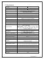
1
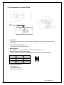
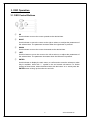
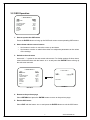
Car License Plate Camera (With Effio WDR) Veilux VSSC-68CDNR-90 User Manual Thanks for purchasing the Veilux VSSC-68CDNR-90 LPR Camera. Before operating the unit, please read the instructions carefully and keep this manual for future reference. 0 Safety Warning 1. Read this manual carefully before installing the unit Please read this manual first for correct installation and operation. 2. Never install the camera on a ceiling that cannot hold its weight The product may fall down and cause damages. 3. Never install the camera near electric or magnetic fields Install the camera away from TV, radio transmitter, magnet, electric motor, transformer, audio speakers since the magnetic fields generate from above devices would distort the video image. 4. Never install or use the camera in areas exposed to water, oil or gas The water, oil or gas may result in operation failure, electric shock or fire. Do not use this unit near water-for example, near a bath tub, wash bowl, kitchen sink, or laundry tub, in a wet basement, near a swimming pool, in an unprotected outdoor installation, or any area which is classified as a wet location. 5. Never face the camera toward the sun Direct sunlight or severe ray may cause fatal damage to sensor and internal circuit. 6. Power Cord Protection Touching the wet power cord with hands or touching the power cord with wet hands may result in electric shock. Power supply cords should be routed so that they are not likely to be walked on or pinched by items placed upon or against them, playing particular attention to cords and plugs, convenience receptacles, and the point where they exit from the appliance. 7. Attachments Do not use attachment not recommended by the product manufacturer as they may cause hazards. 8. Object and Liquid Entry Never push objects of any kind into this product through openings as they may touch dangerous voltage points or short-out parts that could result in a fire or electric shock. Never spill liquid of any kind onto the product. 9. Do not operate the camera in environments where the temperature, humidity or power source is beyond the specified ones Use the camera in suitable environments where the temperature is within -10°C~50°C and humidity below 80%. Use the input power source as this instruction indicated. www.Veilux.net VSSC-68CDNR-90 10. Cleaning Unplug the unit from the outlet before cleaning. Do not use liquid cleaners or aerosol cleaners. Use a damp cloth for cleaning. 11. Never disassemble the camera nor put impurities in it Disassembly or impurities may result in trouble or fire. 12. Stop using when the product emits smoke or abnormal heat 13. Servicing Do not attempt to repair this unit yourself as opening or removing covers may expose you to dangerous voltage or other hazards. Refer all servicing to qualified service personnel. 14. Retain Instructions THE SAFETY AND OPERATING INSTRUCTIONS SHOULD BE RETAINED FOR FUTURE REFERENCE. NOTE: The information in this manual was current when published. The manufacturer reserves the right to revise and improve its products. All specifications are therefore subject to change without notice. www.Veilux.net VSSC-68CDNR-90 Table of Contents 1. INTRODUCTION ........................................................................................................................1 1.1 MAIN FEATURES ............................................................................................................................... 1 1.2 CONTENT LIST ................................................................................................................................. 1 1.3 SPECIFICATIONS ............................................................................................................................... 2 2. CAMERA OVERVIEW................................................................................................................3 2.1 DIMENSIONS .................................................................................................................................... 3 2.2 DESCRIPTION OF CAMERA PARTS ...................................................................................................... 4 3. OSD OPERATION......................................................................................................................6 3.1 OSD CONTROL BUTTONS ................................................................................................................. 6 3.2 OSD OPERATION ............................................................................................................................. 7 4. CONFIGURATION......................................................................................................................8 4.1 LENS.............................................................................................................................................. 8 4.2 EXPOSURE ................................................................................................................................... 9 4.3 WDR............................................................................................................................................. 10 4.4 WHITE BALANCE........................................................................................................................ 12 4.5 2DNR &3DNR (DYNAMIC NOISE REDUCTION) ................................................................................ 14 4.6 DAY/NIGHT.................................................................................................................................. 15 4.7 IMAGE ......................................................................................................................................... 18 4.8 EFFECT ....................................................................................................................................... 20 4.9 SYSTEM ...................................................................................................................................... 23 4.10 EXIT ........................................................................................................................................... 25 www.Veilux.net VSSC-68CDNR-90 1. Introduction Built with Sony's latest Effio DSP and 1/3" 960H Double-speed CCD WD image sensor, VSSC-68CDNR-90 has the capability of achieving resolutions of over 680TVL, the WDR function can produce clear and true image without noise even in tunnels, an environment with very strong light, and can capture vehicle license plate numbers at speed up to 200km/hr (125mile/hr) during the day, and 150km/hr (90mile/hr) at night. The most exciting feature is the Multi-Shutter modes, Scheduled Shutter Mode, Manual Shutter Mode and Auto Shutter Mode. VSSC-68CDNR-90 supports Balun RS-485 remote control to control the OSD remotely. When it comes to Car License Plate Camera, VSSC-68CDNR-90 is definitely ideal to install at any kind of car entrances and exits for capturing car license plates. 1.1 Main Features 1/3" Hyper Wide Dynamic Car License Plate Camera (Effio WDR) Color:680TVL, B/W:700TVL Color:[email protected], B/W:[email protected], Sense-up:[email protected] Capable of Capturing Car License Plate Numbers at High Speed ‧ Day:up to200km/hr (125mile/hr) ‧ Night:up to150km/hr (90mile/hr), with External IR LEDs Self Defined Auto Shutter Speed Range Multi-Language OSD Control Powerful 510X WDR High Light Compensation (HLC) 2D/3D Noise Reduction Sense Up (512x) Functions Digital Image Stabilizer (DIS) E-zoom Function (1~256x) Advanced Motion Detection Function Quadrangle Mosaic Privacy Mask 1.2 Content List Car License Plate Camera (EFFIO WDR): VSSC-68CDNR-90 User’s manual 1 VSSC-68CDNR-90 1.3 Specifications TV System PAL Image Sensor 1/3" Sony 960H EXview HAD CCD II Number of Total Pixels Resolution Minimum Illumination Wide Dynamic Range Video Output 1020(H)x596(V) IR LED ; Working Distance Menu 1.0Vp-p Composite, 75Ω (BNCx2) More than 55dB (AGC off) 0.45 Automatically Switches (Switching Lux Level can be adjusted) Compatible with Infrared Illuminator OSD Control or by RS485 Control TITLE (LOCATION) Title Synchronizing System Digital Day&Night Mode Electronic Shutter Automatic Gain Control White Balance WDR ; BLC ; Fog Reduction INTERNAL / LINE LOCK (for DC/AC and AC version) COLOR / B&W / AUTO / EXT Auto Shutter: Self Defined Auto Shutter Speed Range (20 Steps) Programmable Manual Shutter: 20 Steps, 1/50(60), FL 1/120(100), 1/200, 1/250, 1/300, 1/350, 1/400, 1/450, 1/500, 1/600, 1/750, 1/1,000, 1/1,500,1/2,000, 1/3,000, 1/4,000, 1/10,000, 1/30,000, 1/60,000, 1/100,000 sec. 0~200 Levels (Adjustable Level Settings) ATW / AWB / PUSH LOCK / MANUAL / 3200K / 6300K / ANTI CR WDR / FOG REDUCTION / BLC / OFF High Light Compensation ON / OFF / AUTO Flickerless ON / OFF Dynamic Noise Reduction 3D / 2D Sense Up AUTO (Limit x2~x512) / OFF ON / OFF Digital Image Stabilizer Language 1020(H)x508(V) Color:680TVL, B/W:700TVL ; Sony Effio WDR Color:[email protected], B/W:[email protected], Sense-up:[email protected] 510x Normal Camera Signal to Noise Ratio (S/N) Gamma Correction Mechanical IR Cut Filter (ICR) NTSC ENGLISH / TRADITIONAL CHINESE / SIMPLIFIED CHINESE E-Zoom x1~x256, Pan / Tilt Adjustable Motion Detection ; Privacy ON / OFF (24x16 Zones, Alarm) ; ON / OFF (15 Zones Programmable, Quadrangle Mosaic) Automatic IRIS ; Connector VIDEO / DC ; D4 IRIS Jack Lens Mount Power Supply ; Consumption CS / C mount (With Adaptor Ring) 12Vdc/24Vac (10.8~39Vdc/24Vac) ; 2.0W Operation ; Storage Temp. -10°C~50°C ; -20°C~60°C Operation ; Storage Humidity Maximum: RH80% ; RH90% Dimensions 64(W)×58(H)×123(L)mm Net Weight 350g 2 VSSC-68CDNR-90 2. Camera Overview 2.1 Dimensions 3 VSSC-68CDNR-90 2.2 Description of Camera Parts ① Lens Mount This mount is used to install a CS-mount lens. CS-adaptor ring is required when using a C mount lens. ② Camera Mounting Screw Holes Screw holes for mounting the camera. ③ Mount Adaptor The adaptor can be attached onto the top or the bottom of the unit. ④ Auto Iris Lens Connector (4-pin type) The lens connector supplies the auto-iris lens (not supplied) with DC control signal. PIN NO. 1 2 3 4 ⑤ VIDEO DC + 12V NC IRIS GND DC CONTROL CONTROL + DRIVE + DRIVE - OSD Control Buttons ENTER button UP & DOWN buttons LEFT & RIGHT buttons 4 VSSC-68CDNR-90 ⑥ Video Connector Video can be outputted via this connector. (75Ω). ⑦ IRIS Mode Selection Switch Select DC or VIDEO mode according to the lens. ⑧ Video Connector Video can be outputted via this connector. (75Ω). ⑨ Communication Connectors 1. RS485+ 2. RS4853. Day & Night External Input (controlled by external infrared illuminator) 4. Day & Night Output 5. NC 6. Ground ⑩ Power Input Indicator Light When the camera is connected to a power supply, the indicator light will be on. ⑪ RS-485 Terminal Impedance Switch Set the first and the last equipment terminal impedances as 120Ω and set the rest parallel connection equipment in the middle as HiZ to obtain the best transmitting status. ⑫ Power Input Terminal Connect to the power supply. 5 VSSC-68CDNR-90 3. OSD Operation 3.1 OSD Control Buttons ① UP Use this button to move the cursor upwards to the desired item. ② RIGHT Use this button to move the cursor to the right to select or to adjust the parameters of the selected item. The parameter increases when the right button is pressed. ③ DOWN Use this button to move the cursor downwards to the desired item. ④ LEFT Use this button to move the cursor to the left to select or to adjust the parameters of the selected item. The parameter decreases when the left button is pressed. ⑤ ENTER Use this button to display the main menu, to confirm and to enter the submenus when they’re available. Items with “<┘” symbol in the end contain sub-menus. For further settings of those items, select the desired item with the button or and press the ENTER button to bring up the sub-menu and edit. 6 VSSC-68CDNR-90 3.2 OSD Operation ** MAIN MENU ** AUTO<┘ SET<┘ OFF ATW <┘ SET<┘ AUTO<┘ SET<┘ SET<┘ SET<┘ LENS EXPOSURE WDR WHITE BALANCE 2DNR & 3DNR DAY/NIGHT IMAGE EFFECT SYSTEM EXIT<┘ 1. Start to operate the OSD menu Press the ENTER button to bring up the OSD main menu to start operating OSD menus. 2. Select items with the cursor buttons Use buttons and to move the cursor up and down. Use buttons and to switch the modes or to adjust the parameters or the values of the settings. 3. Switch to the sub-menu Items with “<┘” symbol in the end contain sub-menus. For further settings of those items, select the desired item with the button or and press the ENTER button to bring up the sub-menu and edit. ** MAIN MENU ** ** AUTO IRIS ** LENS EXPOSURE WDR WHITE BALANCE 2DNR & 3DNR DAY/NIGHT IMAGE EFFECT SYSTEM EXIT<┘ AUTO<┘ SET<┘ OFF ATW <┘ SET<┘ AUTO<┘ SET<┘ SET<┘ SET<┘ TYPE SPEED DC |||||||||||||||| 050 RETURN<┘ Sub-Menu Main Menu 4. Return to the previous page Select RETURN and press the ENTER button to return to the previous page. 5. Exit the OSD menu Select EXIT with the button or and press the ENTER button to exit the OSD menu. 7 VSSC-68CDNR-90 4. Configuration 4.1 LENS When the MAIN MENU is displayed on the screen, use the UP and DOWN buttons to the LENS and press the ENTER button to do further setups. ** MAIN MENU ** LENS EXPOSURE WDR WHITE BALANCE 2DNR & 3DNR DAY/NIGHT IMAGE EFFECT SYSTEM EXIT<┘ ** AUTO IRIS ** AUTO<┘ SET<┘ OFF ATW <┘ SET<┘ AUTO<┘ SET<┘ SET<┘ SET<┘ TYPE SPEED DC |||||||||||||||| 050 RETURN<┘ Sub-Menu Main Menu *TYPE When the DC LENS is in use, push IRIS SWITCH on the control board to DC, and the TYPE on the menu will be displayed as DC. When the VIDEO LENS is in use, push IRIS SWITCH on the control board to VIDEO, and the TYPE on the menu will be displayed as VIDEO. *SPEED The speed of DC Lens is in direct ratio to the number you set. The range of the SPEED can be set from 000~255. NOTE: The SPEED function will not work when the TYPE of LENS set to VIDEO. 8 VSSC-68CDNR-90 4.2 EXPOSURE When the MAIN MENU is displayed on the screen, use the UP and DOWN buttons to the EXPOSURE and press the ENTER button to do further setups. ** MAIN MENU ** LENS EXPOSURE WDR WHITE BALANCE 2DNR & 3DNR DAY/NIGHT IMAGE EFFECT SYSTEM EXIT<┘ ** EXPOSURE ** AUTO<┘ SET<┘ OFF ATW <┘ SET<┘ AUTO<┘ SET<┘ SET<┘ SET<┘ MODE BRIGHTNESS SHUT SHUT MAX LOW LUX BRIGHT. AGC GAIN SENSE UP AUTO IRIS |||||||||||||||| 030 1/50 (S) x1.0 |||||||||||||||| 150 OFF RETURN<┘ Sub-Menu Main Menu *MODE Two modes to select from: AUTO IRIS and SHUT+AUTO IRIS. When in AUTO IRIS mode, SHUT is activated and adjustable. When in SHUT+AUTO IRIS mode, SHUT MAX is activated and adjustable. *BRIGHTNESS When the EXPOSURE MENU is displayed on the screen, use the UP and DOWN buttons to the BRIGHTNESS and use LEFT and RIGHT buttons to adjust the screen brightness from 000 to 255. *SHUT(SHUTTER) / SHUT MAX(SHUTTER MAX) The shutter speed is in direct ratio to the number you set. The range of the shutter speed can be set from 1/50-1/100,000(sec). *LOW LUX BRIGHT. (LOW LUX BRIGHTNESS) Use LEFT and RIGHT buttons to adjust Low Lux Brightness. The options are x0.25, x0.5, x0.75, x1.0. *AGC GAIN The bigger the number, the brighter the screen can be. Note that the noise will increase as well. The AGC GAIN range can be set from 000 to 200. *SENSE UP SENSE UP is used to maintain a brilliant, vivid screen image by automatically detecting changes in the level of light under low light level conditions. Select the desired item and press LEFT and RIGHT buttons to adjust the settings. The options are x2, x4, x8, x16, x32, x64, x128, x256, x512, and OFF. 9 VSSC-68CDNR-90 4.3 WDR 1. When the MAIN MENU is displayed on the screen, use the UP and DOWN buttons to WDR and press the ENTER button to do further setups. ** MAIN MENU ** AUTO<┘ SET<┘ OFF ATW <┘ SET<┘ AUTO<┘ SET<┘ SET<┘ SET<┘ LENS EXPOSURE WDR WHITE BALANCE 2DNR & 3DNR DAY/NIGHT IMAGE EFFECT SYSTEM EXIT<┘ The modes under the function are: WDR, BLC, and OFF. 2. Please select the desired item and press LEFT and RIGHT buttons to adjust the settings. *WDR (Wide Dynamic Range) When there are both bright and dark areas at the same time, selecting this mode makes both areas distinctive. ** WDR ** LEVEL |||||||||||||||| 185 DARK |||||||||||||||| |||||||||||||||| 000 BRIGHT 000 RETURN<┘ Sub-Menu under WDR mode. - LEVEL Use the LEVEL function to adjust the brightness of the whole area. Level: 000~255 - DARK Use the DARK function to adjust the brightness of the dark area. Level: 000~255 - BRIGHT Use the BRIGHT function to adjust the brightness of the bright area. Level: 000~255 10 VSSC-68CDNR-90 *BLC (Back Light Compensation) Even when there is a massive backlight behind the object, bright images of the background and the object can still be captured by selecting the BLC mode. ** BLC ** MODE AREA MANUAL LEVEL AUTO LEVEL The modes under the function are: AUTO and AUTO --|||||||||||||||| MANUAL. 008 RETURN<┘ Sub-Menu under BLC mode. - AUTO Set AUTO LEVEL to adjust the BLC automatically. The range is 000~015. - MANUAL Set AREA and MANUAL LEVEL to adjust the BLC value manually. The default AREA is BOTTOM 1/3, and the default LEVEL is MID. Stay with the default value, the bottom 1/3 area will be the brighter area, with the middle level of brightness. AREA: BOTTOM 1/3, TOP 2/3, BOTTOM 2/3, LEFT 2/3, and RIGHT 2/3. MANUAL LEVEL: HIGH, MID, and LOW. *OFF When set as OFF, there’ll be no wide dynamic range. 11 VSSC-68CDNR-90 4.4 WHITE BALANCE The screen color can be adjusted by using the WHITE BALANCE function. 1. Please use the UP and DOWN buttons to WHITE BALANCE on the MAIN MENU and press the ENTER button to do further setups. 2. Please select the desired item and press LEFT and RIGHT buttons to adjust the settings. ** MAIN MENU ** LENS EXPOSURE WDR WHITE BALANCE 2DNR & 3DNR DAY/NIGHT IMAGE EFFECT SYSTEM EXIT<┘ AUTO<┘ SET<┘ OFF ATW <┘ SET<┘ AUTO<┘ SET<┘ SET<┘ SET<┘ The modes under the function are: ATW, AWB, 3200K, 6300K, ANTI CR, MANUAL, and PUSH LOCK. *ATW (Auto Tracking White Balance) This mode can be used within the color temperature range from 1800°K to 10500°K (e.g., around fluorescent lights, outdoors, around sodium vapor lamps or inside tunnels). *AWB (Auto White Balance) Select this to allow the camera automatically adjust the white balance under all conditions. *3200K Select this when the color temperature is around 3200°K (when surrounded by sodium lights). *6300K Select this when the color temperature is around 6300°K. *ANTI CR (Color rolling suppression) Select to set the white balance mode to the ANTI CR mode. Follow the instructions on the screen. Wait for a few seconds for the camera to set up. When completed, there will be a message displayed on the screen. NOTE: The White Balance cannot fully function under the following conditions. When the following occurred, please select PUSH LOCK Mode. < When there’s a higher temperature surrounded the object. < When there’s darkness surrounded the object. < When there’s a fluorescent light surrounded the object or where the light changes all the time. 12 VSSC-68CDNR-90 *MANUAL The manual adjustment mode enables a more precise adjustment. Increase and/or decrease the red and blue color values according to the color changes of the object to set the suitable color temperature. RED color vale ranges from 000 to 255. BLUE color value ranges from 000 to 255. *PUSH LOCK Follow the instructions on the screen. Wait for a few seconds for the camera to set up. When completed, there will be a message displayed on the screen. To find the optimal setting for the current luminance environment in this mode, point the camera towards a sheet of white paper and press the ENTER button. Whenever the condition changes, readjust it. 13 VSSC-68CDNR-90 4.5 2DNR &3DNR (Dynamic Noise Reduction) ** MAIN MENU ** LENS EXPOSURE WDR WHITE BALANCE 2DNR & 3DNR DAY/NIGHT IMAGE EFFECT SYSTEM EXIT<┘ ** 2DNR & 3DNR ** AUTO<┘ SET<┘ OFF ATW <┘ SET<┘ AUTO<┘ SET<┘ SET<┘ SET<┘ 2DNR 3DNR MIDLOW MIDLOW RETURN<┘ Sub-Menu under 2DNR & 3DNR mode. 1. When the noise level is reduced, the camera performance can apparently be improved. When recording digitally, the image file size can be lessened by selecting the noise reduction. As the level of gain changes, the background noise in the low light level decreases automatically. 2. Please use the UP and DOWN buttons to 2DNR & 3DNR on the MAIN MENU and press the ENTER button to do further setups. 3. Please select the desired item and press LEFT and RIGHT buttons to adjust the settings. 14 VSSC-68CDNR-90 4.6 DAY/NIGHT The camera can be set in Color or B/W mode in the Day/Night function. NOTE: 1. EXT function is not available for OC version. 2. Communication Connectors (including RS485) are not available for all cameras. Please refer to 2.2 for details. ** MAIN MENU ** AUTO<┘ SET<┘ OFF ATW <┘ SET<┘ AUTO<┘ SET<┘ SET<┘ SET<┘ LENS EXPOSURE WDR WHITE BALANCE 2DNR & 3DNR DAY/NIGHT IMAGE EFFECT SYSTEM EXIT<┘ The modes under the function are: COLOR, B&W, AUTO, EXTERNAL. 1. Please use the UP and DOWN buttons to DAY/NIGHT on the MAIN MENU and press the ENTER button to enter. 2. Please select the desired item and press LEFT and RIGHT buttons to adjust the settings. *COLOR The COLOR / DAY mode. *B&W The BLACK & WHITE / NIGHT mode. *AUTO ** DAY/NIGHT AUTO ** LIVE LEVEL DAY->NIGHT NIGHT->DAY DELAY TIME BURST NIGHT OUTPUT ||||||||||||||||||||| 063 ||||||||||||||||||||| 003 ||||||||||||||||||||| 025 ||||||||||||||||||||| 005 OFF 5V RETURN<┘ Sub-Menu under the DAY / NIGHT AUTO mode The camera will switch to DAY/Color mode or NIGHT/B&W mode according to the set value. •LIVE LEVEL: This indicates the current light level. •DAYNIGHT: When the camera detects the current light level is lower than the set value, it’ll switch from DAY mode to NIGHT mode. Value: 0~63. 15 VSSC-68CDNR-90 •NIGHTDAY: When the camera detects the current light level is higher than the set value, it’ll switch from NIGHT mode to DAY mode. Value: 0~63. NOTE: 1. The setting differences between DAY NIGHT and NIGHTDAY should be more than 5, or the camera will keep switching from DAY NIGHT and NIGHTDAY constantly. 2. The infrared illuminator is not recommended to use under AUTO mode. Please switch to EXTERNAL mode when an infrared illuminator is installed. •DELAY TIME: Sometimes there’s only a sudden and short light level change. Delay time can be set to avoid switching too fast. The camera will switch the mode after the set DELAY TIME passed. DELAY TIME can be set from 0 to 255 seconds. •BURST : Turn the BURST function off to reduce the color noise under B&W mode. However, not every DVR machines can receive video signals without the color burst signals. If the camera cannot switch back to COLOR mode from B&W mode, please turn the BURST function on. NOTE: The BURST function is adjustable under B&W, EXTERNAL and SCHEDULE mode. •NIGHT OUTPUT OUTPUT DNO SYSTEM COLOR B&W GND 5V 5V GND GND 5V When the camera switches modes, the external components will be alerted, via DNO pin of the communication connector. 16 VSSC-68CDNR-90 *EXTERNAL ** EXTERNAL ** NIGHT INPUT BURST HIGH OFF RETURN<┘ Sub-Menu under the DAY / NIGHT EXTERNAL mode EXTERNAL mode allows the user to switch the DAY/NIGHT mode with external signals. For example, you can synchronize the DAY/NIGHT mode between the camera and the infrared LED illuminator. For the camera with the light sensor, it is suggested to set the DAY/NIGHT mode to EXTERNAL to ensure the best result. NIGHT INPUT: Select input level. LOW : It will be the COLOR mode if the input signal is HIGH. On the contrary, it will be the B&W mode. HIGH : It will be the B&W mode if the input signal is HIGH. On the contrary, it will be COLOR mode. HIGH :3~12V or OPEN LOW : GND INPUT SYSTEM DNI HIGH LOW LOW HIGH COLOR B&W B&W COLOR When the external infrared illuminator is in use, the camera can switch to COLOR or B/W mode, via DNI pin of the communication connector. 17 VSSC-68CDNR-90 4.7 IMAGE ** MAIN MENU ** LENS EXPOSURE WDR WHITE BALANCE 2DNR & 3DNR DAY/NIGHT IMAGE EFFECT SYSTEM EXIT<┘ ** IMAGE ** AUTO<┘ SET<┘ OFF ATW <┘ SET<┘ AUTO<┘ SET<┘ SET<┘ SET<┘ RESOLUTION SHARPNESS SHARP. SUP. CONTRAST SATURATION HUE MIRROR POS./NEG. WHITE PIXEL COMP MID ||||||||||||||||||||| 010 ||||||||||||||||||||| 010 ||||||||||||||||||||| 000 ||||||||||||||||||||| 000 ||||||||||||||||||||| 000 NORMAL OFF SET<┘ RETURN<┘ Sub-Menu under the Image Function 1. Please use the UP and DOWN buttons to IMAGE on the SETUP MENU and press ENTER button to enter. 2. Please select the desired item and press LEFT and RIGHT buttons to adjust the settings. *RESOLUTION Options are HIGH, MIDHIGH, MID, MIDLOW, LOW, and OFF. *SHARPNESS Level: 000~015. The contour of the video image becomes cleaner and more distinguished as the level of SHARPNESS increases. If the level goes up extremely, it may affect the video image and cause noise. *SHARP. SUP. (SHARPNESS SUPPRESION) Level: 000~015. Select to adjust the value of the sharpness in low Lux environment. *CONTRAST Level: -032~031 Select to adjust the value of the contrast. *SATURATION Level: -050~050 Select to adjust the value of the gain. *HUE Level: -050~050 Select to adjust the value of the hue. *MIRROR NORMAL, VERTICAL (vertical rotated), MIRROR (horizontal rotated), and ROTATE (vertical and horizontal rotated). *POS. / NEG. ON/OFF. Positive/Negative Reversal. function. Select ON or OFF to enable or disable this 18 VSSC-68CDNR-90 *WHITE PIXEL COMP (WHITE PIXEL COMPENSATION) Level: 000~010. Select to enter the sub-menu for further settings. Click START to search for the white pixels of CCD, and set MARKER to ON to display the pixels on the screen. Decrease the THRESHOLD value to find more white pixels, or increase the value to reduce the number of white pixels. 19 VSSC-68CDNR-90 4.8 EFFECT ** MAIN MENU ** ** EFFECT ** AUTO<┘ SET<┘ OFF ATW <┘ SET<┘ AUTO<┘ SET<┘ SET<┘ SET<┘ LENS EXPOSURE WDR WHITE BALANCE 2DNR & 3DNR DAY/NIGHT IMAGE EFFECT SYSTEM EXIT<┘ MOTION DET PRIVACY MASK DIS E-ZOOM HLC OFF OFF OFF OFF SET<┘ RETURN<┘ 1. Please use the UP and DOWN buttons to EFFECT on the MAIN MENU and press ENTER button to enter. 2. Please select the desired item and press LEFT and RIGHT buttons to adjust the settings. *MOTION DETECTION Options are ON/OFF. Set to ON and click ENTER to bring up submenu for further settings. ** MOTION DET ** DETECT SENSE BLOCK DISP DETECT AREA MONITOR AREA ALARM OUT ALARM TIME ||||||||||||||||||||| 115 ON SET<┘ SET<┘ OFF - RETURN<┘ - DETECT SENSE Sensitivity can be set from 0 to 127. The higher the number, the more sensible the camera can be. - BLOCK DISP Set the block display to ON/OFF. - DETECT AREA Press SET to enter the sub-menu, and set the detect area. - MONITOR AREA Press SET to enter the sub-menu, and set the detect area. 20 VSSC-68CDNR-90 - ALARM OUT (Only available to cameras with Communication Connectors) Choose ON to output the alarm; connect the alarm device to the ALO of the communication port on the rear panel so that the alarm can be output. Be sure to turn off all the power before connecting. Connect the ALARM terminal here. - ALARM TIME (Only available to cameras with Communication Connectors) Alarm time can be set from 000 to 255 seconds. *PRIVACY MASK Options are ON/OFF. Set to ON and click ENTER to bring up submenu for further settings. ** PRIVACY MASK ** AREA SEL MODE POSTION COLOR TRANSP MOSAIC 1/15 ON SET<┘ BLACK 0.50 OFF RETURN<┘ - AREA SEL There’re 1-15 areas which can be masked. - MODE Options are ON/OFF. Choose ON to show the protected area on the screen, OFF to hide the protected area on the screen. - POSITION Press ENTER button for further settings. Adjust the area size and shape by dragging the vertices of the quadrilateral. Push ENTER to switch the vertices in the sequence of left top, right top, left bottom and right bottom, and push ENTER again to return to PRIVACY MASK submenu. - COLOR Use LEFT and RIGHT buttons to adjust the color of PRIVACY MASK. The options are BLACK, RED, GREEN, BLUE, YELLOW, CYAN, MAGENTA and WHITE. 21 VSSC-68CDNR-90 - - TRANSP Use LEFT and RIGHT buttons to adjust the transparency of PRIVACY MASK. The options are 0.00, 0.50, 0.75 and 1.00. Note that the MOSAIC will be disabled when the transparency set to 1.00. MOSAIC Options are ON/OFF. Use LEFT and RIGHT buttons to display the block in mosaic or not. *DIS (Digital Image Stabilizer) Options are OFF and ON. When set to ON, the DIS function will help to prevent vibration, and the E-Zoom function will be disabled. *E-ZOOM ** E-ZOOM ** RATIO PAN TILT ||||||||||||||||||||| ||||||||||||||||||||| ||||||||||||||||||||| 001 000 001 RETURN<┘ Sub-Menu under the E-ZOOM mode Select ON and press ENTER button to do further setups. Options are RATIO 001~256 (zoom in 1 to 256 times), PAN -512~511 (horizontal zoomed-in viewing), and TILT 001~256 (vertical zoom-in viewing). *HLC (High Light Compensation) ** HLC ** MODE CLIP LEVEL SCALE OFF ||||||||||||||||||||| 010 ||||||||||||||||||||| 010 RETURN<┘ Sub-Menu under the HLC mode - MODE Select to choose HLC mode from OFF, ON, and AUTO. - CLIP LEVEL Adjust the value of the HLC clip level from 000 to 255. - SCALE Adjust the value of the HLC scale from 000 to 015. 22 VSSC-68CDNR-90 4.9 SYSTEM 1. Please use the UP and DOWN buttons to SYSTEM on the MAIN MENU. ** SYSTEM ** ** MAIN MENU ** LENS EXPOSURE WDR WHITE BALANCE 2DNR & 3DNR DAY/NIGHT IMAGE EFFECT SYSTEM EXIT<┘ CAMERA TITLE COMM SYNC LANGUAGE FIRMWARE RESTORE AUTO<┘ SET<┘ OFF ATW <┘ SET<┘ AUTO<┘ SET<┘ SET<┘ SET<┘ OFF SET<┘ INT ENGLISH 1.0 11-06-02 NO RETURN<┘ 2. Please select the desired item and press LEFT and RIGHT buttons to adjust the settings. NOTE: The version of FIRMWARE shown on the above is for reference only. The actual version varies by the production. *CAMERA TITLE ** CAMERA TITLE ** CAMERA ABCDEFGHIJKLMNOPQRSTUV WXYZ0123456789 - ! ” # $ % & ’ ( ) _ ` , ¥ : ; <=>?@\ ^ * . x+/ ← →↑↓ CLR POS RETURN<┘ - ← →↑↓ Select ←, →, ↑ or ↓ with the character selection cursor, and click the ENTER button to move the cursor in the direction of the arrow. - CLR Select to clear one letter of the input. - POS Adjust the position of the camera ID. 23 VSSC-68CDNR-90 *COMM Select SET<┘ to enter sub-menu for further settings. 1. The CAM ID, PROTOCOL and BAUD RATE will be displayed for the first five seconds on boot. 2. Changes made to the CAM ID, PROTOCOL and BAUD RATE will only take effect after you exit the COMM page. This is to prevent the camera from unexpected disconnecting caused by remote access. •CAMERA ID: 1~1024 •DISP CAM ID: OFF/TOP-LEFT/TOP-RIGHT/BOTTOM-LEFT/BOTTOM-RIGHT. Select to hide the CAMERA ID or to adjust the CAM ID position. •BAUD RATE: 2400/4800/9600/19200/38400 •PROTOCOL: PELCO D, PELCO-P NOTE: The COMM function is available for models with RS485 only. *SYNC (Only available to cameras with AC power input) Use the LEFT & RIGHT buttons to switch SYNC mode between INT(Internal) and L.L.(Line Lock). Set to L.L. and click ENTERS to bring up submenu for further settings. *LANGUAGE Use the LEFT & RIGHT buttons to select the language preference. The options are: •ENGLISH *FIRMWARE Please refer to the actual firmware. (The figure shown on above is for reference only.) *RESTORE Select NO to exit, or select YES to restore all the settings to the default value. NOTE: The following items will not be restored: CAM ID, PROTOCOL, BAUD RATE and LANGUAGE. 24 VSSC-68CDNR-90 4.10 EXIT Select EXIT to automatically save the settings made and exit the MENU. ** MAIN MENU ** LENS EXPOSURE WDR WHITE BALANCE 2DNR & 3DNR DAY/NIGHT IMAGE EFFECT SYSTEM EXIT<┘ AUTO<┘ SET<┘ OFF ATW <┘ SET<┘ AUTO<┘ SET<┘ SET<┘ SET<┘ 25 VSSC-68CDNR-90