1
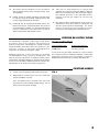
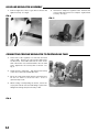
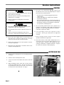
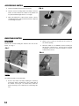
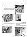
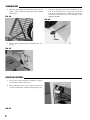
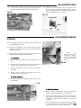
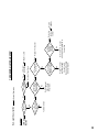
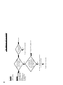
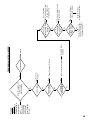
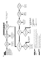
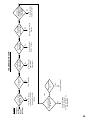
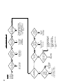
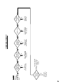
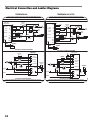
Owner's Manual and Instructions
Tradesman Construction Heaters
MODELS
OUTPUT (BTUH)
CP400
400,000
FUEL
Propane Vapor
Withdrawal
Certification by:
Congratulations!
You have purchased the finest portable forced air construction heater available.
Your new L.B. White heater incorporates the benefits from the most experienced
manufacturer of heating products using state-of-the-art technology.
We, at L.B. White, thank you for your confidence in our products and welcome any
suggestions or comments you may have...call us, toll-free, at (800) 345-7200.
ATTENTION ALL USERS
This heater has been tested and evaluated by C.S.A. International in accordance with
the requirements of Standard ANSI Z83.7 CSA 2.14 and is listed and approved as a
direct gas-fired forced-air construction heater with application for the temporary
heating of buildings under construction, alteration, or repair. If you are considering
using this product for any application other than its intended use, then please
contact your fuel gas supplier, or the L.B. White Co., Inc.
150-20530-F
GENERAL HAZARD WARNING
■ Failure to comply with the precautions and instructions provided with this heater, can result in:
— Death
— Serious bodily injury or burns
— Property damage or loss from fire or explosion
— Asphyxiation due to lack of adequate air supply or carbon monoxide poisoning
— Electrical shock
■ Read this Owner’s Manual before installing or using this product.
■ Only properly-trained service people should repair or install this heater.
■ Save this Owner’s Manual for future use and reference.
■ Owner’s Manuals and replacement labels are available at no charge. For assistance, contact
L.B. White at 800-345-7200.
WARNING
■ Proper gas supply pressure must be provided to the inlet of the heater.
■ Refer to data plate for proper gas supply pressure.
■ Gas pressure in excess of the maximum inlet pressure specified at the heater inlet can cause
fires or explosions.
■ Fires or explosions can lead to serious injury, death, or building damage.
■ Gas pressure below the minimum inlet pressure specified at the heater inlet may cause
improper combustion.
■ Improper combustion can lead to asphyxiation or carbon monoxide poisoning and therefore
serious injury or death.
WARNING
Fire and Explosion Hazard
■ Not for home or recreational vehicle use.
■ Installation of this heater in a home or
recreational vehicle may result in a fire or
explosion.
■ Fire or explosions can cause property
damage or loss of life.
FOR YOUR SAFETY
If you smell gas:
1. Open windows.
2. Don't touch electrical switches.
3. Extinguish any open flame.
4. Immediately call your gas supplier.
FOR YOUR SAFETY
Do not store or use gasoline or other
flammable vapors and liquids in the vicinity of
this or any other appliance.
WARNING
Fire and Explosion Hazard
■ Keep solid combustibles a safe distance
away from the heater.
■ Solid combustibles include wood, paper, or
plastic products, building materials and
dust.
■ Do not use the heater in spaces which
contain or may contain volatile or airborne
combustibles.
■ Volatile or airborne combustibles include
gasoline, solvents, paint thinner, dust
particles or unknown chemicals.
■ Failure to follow these instructions may
result in a fire or explosion.
■ Fire or explosions can lead to property
damage, personal injury or loss of life.
2
Table of Contents
SECTION
PAGE
General Information . . . . . . . . . . . . . . . . . . . . . . . . . . . . . . . . . . . . . . . . . . . . . . . . . . . . . . . . . . . . . . . . . . .3
Heater Specifications . . . . . . . . . . . . . . . . . . . . . . . . . . . . . . . . . . . . . . . . . . . . . . . . . . . . . . . . . . . . . . . . . .4
Safety Precautions . . . . . . . . . . . . . . . . . . . . . . . . . . . . . . . . . . . . . . . . . . . . . . . . . . . . . . . . . . . . . . . . . . . .5
Installation and Assembly Instructions
General . . . . . . . . . . . . . . . . . . . . . . . . . . . . . . . . . . . . . . . . . . . . . . . . . . . . . . . . . . . . . . . . . . . . . . . . .7
Propane Gas Supply Sizing . . . . . . . . . . . . . . . . . . . . . . . . . . . . . . . . . . . . . . . . . . . . . . . . . . . . . . . . . .8
Carrying Handle . . . . . . . . . . . . . . . . . . . . . . . . . . . . . . . . . . . . . . . . . . . . . . . . . . . . . . . . . . . . . . . . . . .8
Hose and Regulator Assembly . . . . . . . . . . . . . . . . . . . . . . . . . . . . . . . . . . . . . . . . . . . . . . . . . . . . . . .9
Connecting Regulator to Propane Gas Supply Cylinder . . . . . . . . . . . . . . . . . . . . . . . . . . . . . . . . . . .9
Start-Up Instructions . . . . . . . . . . . . . . . . . . . . . . . . . . . . . . . . . . . . . . . . . . . . . . . . . . . . . . . . . . . . . . . . .10
Shut-Down Instructions . . . . . . . . . . . . . . . . . . . . . . . . . . . . . . . . . . . . . . . . . . . . . . . . . . . . . . . . . . . . . . .10
Cleaning Instructions . . . . . . . . . . . . . . . . . . . . . . . . . . . . . . . . . . . . . . . . . . . . . . . . . . . . . . . . . . . . . . . . .11
Maintenance Instructions . . . . . . . . . . . . . . . . . . . . . . . . . . . . . . . . . . . . . . . . . . . . . . . . . . . . . . . . . . . . .11
Service Instructions
General . . . . . . . . . . . . . . . . . . . . . . . . . . . . . . . . . . . . . . . . . . . . . . . . . . . . . . . . . . . . . . . . . . . . . . . .12
Motor and Fan . . . . . . . . . . . . . . . . . . . . . . . . . . . . . . . . . . . . . . . . . . . . . . . . . . . . . . . . . . . . . . . . . .12
Air Proving Switch . . . . . . . . . . . . . . . . . . . . . . . . . . . . . . . . . . . . . . . . . . . . . . . . . . . . . . . . . . . . . . . .13
Backflash Switch . . . . . . . . . . . . . . . . . . . . . . . . . . . . . . . . . . . . . . . . . . . . . . . . . . . . . . . . . . . . . . . . .13
Igniter . . . . . . . . . . . . . . . . . . . . . . . . . . . . . . . . . . . . . . . . . . . . . . . . . . . . . . . . . . . . . . . . . . . . . . . . . .14
Burner Orifice . . . . . . . . . . . . . . . . . . . . . . . . . . . . . . . . . . . . . . . . . . . . . . . . . . . . . . . . . . . . . . . . . . .14
Thermostat . . . . . . . . . . . . . . . . . . . . . . . . . . . . . . . . . . . . . . . . . . . . . . . . . . . . . . . . . . . . . . . . . . . . .15
Ignition Control . . . . . . . . . . . . . . . . . . . . . . . . . . . . . . . . . . . . . . . . . . . . . . . . . . . . . . . . . . . . . . . . . .15
Gas Control Valve . . . . . . . . . . . . . . . . . . . . . . . . . . . . . . . . . . . . . . . . . . . . . . . . . . . . . . . . . . . . . . . .16
Gas Pressure Checks . . . . . . . . . . . . . . . . . . . . . . . . . . . . . . . . . . . . . . . . . . . . . . . . . . . . . . . . . . . . .16
Troubleshooting Information . . . . . . . . . . . . . . . . . . . . . . . . . . . . . . . . . . . . . . . . . . . . . . . . . . . . . . . . . . .17
Electrical Connection and Ladder Diagrams . . . . . . . . . . . . . . . . . . . . . . . . . . . . . . . . . . . . . . . . . . . . . .25
Heater Component Function . . . . . . . . . . . . . . . . . . . . . . . . . . . . . . . . . . . . . . . . . . . . . . . . . . . . . . . . . . .26
Parts Identification
Parts Schematic . . . . . . . . . . . . . . . . . . . . . . . . . . . . . . . . . . . . . . . . . . . . . . . . . . . . . . . . . . . . . . . . .27
Parts List . . . . . . . . . . . . . . . . . . . . . . . . . . . . . . . . . . . . . . . . . . . . . . . . . . . . . . . . . . . . . . . . . . . . . . .28
Warranty Policy . . . . . . . . . . . . . . . . . . . . . . . . . . . . . . . . . . . . . . . . . . . . . . . . . . . . . . . . . . . . . . . . . . . . .29
Replacement Parts and Service . . . . . . . . . . . . . . . . . . . . . . . . . . . . . . . . . . . . . . . . . . . . . . . . . . . . . . . .29
General Information
This Owner's Manual includes all options and accessories
commonly used on this heater.
When calling for technical service assistance, or for other
specific information, always have model number,
configuration number and serial number available. This
information is contained on the dataplate.
This manual will instruct you in the operation and care of
your unit. Have your qualified installer review this manual
with you so that you fully understand the heater and how it
functions.
3
The gas supply line installation, installation of the heater,
and repair and servicing of the heater requires continuing
expert training and knowledge of gas heaters and should
not be attempted by anyone who is not so qualified. See
page 6 for definition of the necessary qualifications.
Contact your local L.B. White distributor or the L.B. White
Co., Inc. for assistance, or if you have any questions about
the use of the equipment or its application.
The L.B. White Co., Inc. has a policy of continuous product
improvement. It reserves the right to change specifications
and design without notice.
Heater Specifications
Model
SPECIFICATIONS
CP400
Propane
Gas
Fuel Type
Maximum Input (BTUH)
Ventilation Air Required
to Support Combustion
400,000
1,582 CFM
Burner Manifold Pressure
Inlet Gas Supply
Pressure Acceptable at
the Inlet of the Heater
for Purpose of Input
Adjustment
4 PSI
MAX.
4 PSI
MIN.
4 PSI
Fuel Consumption Per Hour
18.53 lbs.
Sleeve Bearing
Motor Characteristics
1/5 H.P., 3,200 RPM
Electrical Supply
(Volts/Hz/Phase)
115/60/1
STARTING
Amp Draw
3.7
CONTINUOUS
OPERATION
Dimensions (Inches)
LxWxH
Minimum Safe
Distances From
Nearest
Combustible
Materials
2.4
33 1/4 x 13 1/2 x 18 1/2
TOP
SIDES
BACK
BLOWER
OUTLET
GAS SUPPLY
CYLINDER
Net Weight
Shipping Weight
Minimum Ambient Temperature
in Which Heater May Be Used
7 ft.
5 ft.
5 ft.
15 ft.
10 ft.
51 lbs.
67 lbs.
- 20ºF
4
Safety Precautions
WARNING
■
■
■
■
■
Asphyxiation Hazard
Do not use this heater for heating human living
Owner’s Manual, heater dataplate, or contact the L.B.
quarters.
White Company to determine combustion air ventilation
requirements of the heater.
Do not use in unventilated areas.
■ Lack of proper ventilation air will lead to improper
The flow of combustion and ventilation air must not be
combustion.
obstructed.
■ Improper combustion can lead to carbon monoxide
Proper ventilation air must be provided to support the
poisoning leading to serious injury or death. Symptoms
combustion air requirements of the heater being used.
of carbon monoxide poisoning can include headaches,
dizziness and difficulty in breathing.
Refer to the specification section of the heater’s
FUEL GAS ODOR
Propane gas and natural gas have man-made odorants added specifically for detection of fuel gas leaks.
If a gas leak occurs, you should be able to smell the fuel gas.
THAT’S YOUR SIGNAL TO GO INTO IMMEDIATE ACTION!
■ Do not take any action that could ignite the fuel gas. Do
not operate any electrical switches. Do not pull any
power supply or extension cords. Do not light matches
or any other source of flame. Do not use your
telephone.
■ Get everyone out of the building and away from the area
immediately.
■ Close all propane gas tank or cylinder fuel supply valves,
or the main fuel supply valve located at the meter if you
use natural gas.
■ Propane gas is heavier than air and may settle in low
areas. When you have reason to suspect a propane
leak, keep out of all low areas.
■ Use your neighbor’s phone and call your fuel gas
supplier and your fire department. Do not re-enter the
building or area.
■ Stay out of the building and away from the area until
declared safe by the firefighters and your fuel gas
supplier.
■ FINALLY, let the fuel gas service person and the
firefighters check for escaped gas. Have them air out
the building and area before you return. Properly
trained service people must repair the leak, check for
further leakages, and then relight the appliance for you.
ODOR FADING -- NO ODOR DETECTED
■ Some people cannot smell well. Some people cannot
smell the odor of the man-made chemical added to
propane or natural gas. You must determine if you can
smell the odorant in these fuel gases.
■ Learn to recognize the odor of propane gas and natural
gas. Local propane gas dealers will be more than happy
to give you a scratch and sniff pamphlet. Use it to
become familiar with the fuel gas odor.
■ Smoking can decrease your ability to smell. Being
around an odor for a period of time can affect your
sensitivity to that particular odor.
■ The odorant in propane gas and natural gas is colorless
and the intensity of its odor can fade under some
circumstances.
■ If there is an underground leak, the movement of gas
through the soil can filter the odorant.
■ Propane gas odor may differ in intensity at different
levels. Since propane gas is heavier than air, there may
be more odor at lower levels.
■ Always be sensitive to the slightest gas odor. If you
continue to detect any gas odor, no matter how small,
treat it as a serious leak. Immediately go into action as
discussed previously.
ATTENTION -- CRITICAL POINTS TO REMEMBER!
■ Propane gas has a distinctive odor. Learn to recognize
these odors. (Reference Fuel Gas Odor and Odor Fading
sections above.)
■ Even if you are not properly trained in the service and
repair of the heater, ALWAYS be consciously aware of
the odors of propane gas and natural gas.
■ If you have not been properly trained in repair and service
of propane gas then do not attempt to light heater,
perform service or repairs, or make any adjustments to
the heater on the propane gas fuel system.
■ A periodic sniff test around the heater or at the heater’s
joints; i.e. hose, connections, etc., is a good safety
practice under any conditions. If you smell even a small
amount of gas, CONTACT YOUR FUEL GAS SUPPLIER
IMMEDIATELY. DO NOT WAIT!
5
1. Do not attempt to install, repair, or service this heater
or the gas supply line unless you have continuing
expert training and knowledge of gas heaters.
Qualifications for service and installation of this
equipment are as follows:
a. To be a qualified gas heater service person, you
must have sufficient training and experience to
handle all aspects of gas-fired heater installation,
service and repair. This includes the task of
installation, troubleshooting, replacement of
defective parts and testing of the heater. You
must be able to place the heater into a continuing
safe and normal operating condition. You must
completely familiarize yourself with each model
heater by reading and complying with the safety
instructions, labels, Owner’s Manual, etc., that is
provided with each heater.
6. For safety, this heater is equipped with an auto reset
backflash switch, and an air proving switch. Never
operate the heater with any safety device that has
been bypassed. Do not operate this heater unless
these features are fully functioning.
7. Do not locate fuel gas containers or fuel supply hoses
anywhere near the blower outlet of the heater.
8. Do not block air intakes or discharge outlets of the
heater. Doing so may cause improper combustion or
damage to heater components leading to property
damage.
9. The hose assembly shall be visually inspected on a
daily basis after heater relocation and when the
heater is in use. If it is evident there is excessive
abrasion or wear, or if the hose is cut, it must be
replaced prior to the heater being put into operation.
The hose assembly shall be protected from building
materials, and contact with hot surfaces during use.
The hose assembly shall be that specified by the
manufacturer. See parts list.
b. To be a qualified gas installation person, you must
have sufficient training and experience to handle
all aspects of installing, repairing and altering gas
lines, including selecting and installing the proper
equipment, and selecting proper pipe and tank
size to be used. This must be done in accordance
with all local, state and national codes as well as
the manufacturer’s requirements.
10. Check for gas leaks and proper function upon heater
installation, when relocating, and after servicing.
Refer to leak check instructions within installation
section of this manual.
c. In the Commonwealth of Massachusetts, this
product must be installed by a gas fitter licensed
by the Commonwealth of Massachusetts.
11. This heater should be inspected for proper operation
by a qualified service person before each use and at
least annually.
2. All installations and applications of L.B. White heaters
must meet all relevant local, state and national
codes. Included are L.P. gas, natural gas, electrical,
and safety codes. Your local fuel gas supplier, a local
licensed electrician, the local fire department or
similar government agencies, or your insurance agent
can help you determine code requirements.
12. Always turn off the gas supply to the heater if the
heater is not going to be used in the heating of the
work space.
Also refer to:
-- ANSI/NFPA 58, latest edition, Standard for
Storage and Handling of Liquefied Petroleum
Gas and/or
-- ANSI Z223.1/NFPA 54, National Fuel Gas
Code
13. This heater is equipped with a three-prong
(grounding) plug for your protection against shock
hazard and must be plugged directly into a properly
grounded three-prong receptacle. Failure to use a
properly grounded receptacle can result in electrical
shock, personal injury, or death.
14. If gas flow is interrupted and flame goes out, do not
relight the heater until you are sure that all gas that
may have accummulated has cleared away. In any
event, do not relight the heater for at least 5 minutes.
15.
-- ANSI/NFPA 70, National Electrical Code
3. We cannot anticipate every use which maybe made of
our heaters. Check with the local fire safety authority
if you have questions about applications.
4. Forced air heaters shall not be directed toward any
propane gas container within 20 feet (6.10 meters).
Do not wash the heater. Use only compressed air, a
soft brush or dry cloth to clean the interior of the
heater and it’s components.
5. Use only the regulator supplied with the heater. The
heater must be regulated at all times for proper
operation.
The heater requires a minimum 500 gallon propane
tank for proper gas supply pressure and operation. A
larger tank may be required depending upon
temperature conditions at the site.
16. When the heater is to be stored indoors, the
connection between the L.P. gas supply container
and the heater must be disconnected. The container
must be removed from the heater and stored in
accordance with the Standard for the Staorage and
Handling of Liquefied Petrolem Gases, ANSI / NFPA
58.
17. Propane gas supply containers have left handed
threads. Always use the appropriate wrench to make
a connection to tighten or loosen the regulator’s
P.O.L. fitting at the container’s gas supply valve.
6
Installation and Assembly Instructions
GENERAL
-- Check all pipe connections, hose connections,
fittings and adapters upstream of the gas
control with approved gas leak detectors.
WARNING
Fire and Explosion Hazard
Can cause property damage, severe injury or death
-- In the event a gas leak is detected, check the
components involved for cleanliness and
proper application of pipe compound before
further tightening.
To avoid dangerous accumulation of fuel gas, turn
off gas supply at the heater service valve before
starting installation, and perform gas leak test after
completion of installation.
-- Tighten the gas connections as necessary to
stop the leak.
1. Read all safety precautions and follow L. B. White
recommendations when installing this heater. If
during the installation or relocating of heater, you
suspect that a part is damaged or defective, call a
qualified service agency for repair or replacement.
-- After all connections are checked and any
leaks are stopped, turn on the main burner.
2. Ensure the heater is properly positioned before use.
The heater must be installed on a level, flat,and
stable surface when in operation and according to
minimum safe distances from combustible materials.
Safe distances are given on the heater dataplate and
on page 4 of this manual.
-- With the main burner in operation, check all
connections, hose connections, fittings and
joints as well as the gas control valve inlet and
outlet connections with approved gas leak
detectors.
3. This heater is approved for indoor use only. The
heater shall be installed so it is not directly exposed
to water spray,rain, and /or dripping water.
-- If a leak is detected, check the components
involved for cleanliness in the thread areas
and proper application of pipe compound
before further tightening.
-- Stand clear while the main burner ignites to
prevent injury caused from hidden leaks that
could cause flashback.
-- Tighten the gas connection as necessary to
stop the leak.
4. The heater’s gas pressure regulator (with pressure
relief valve) must be protected from adverse weather
conditions (rain, ice, snow) as well as from building
materials (tar, concrete, plaster, etc.) which can affect
safe operation and could result in property damage or
injury.
5. Heaters used in the vicinity of combustible tarpaulins,
canvas, plastics, wind barriers, or similar coverings
shall be located at least 10 feet from the coverings.
The coverings shall be securely fastened to prevent
ignition or upsetting of the heater due to wind action
on the covering or other material.
6. Ensure that all accessories that ship with the heater
have been installed.
7. Check all connections for gas leaks using approved
gas leak detectors. Gas leak testing is performed as
follows:
WARNING
■
■
■
■
7
Fire and Explosion Hazard
Do not use open flame (matches, torches, candles,
etc.) in checking for gas leaks.
Use only approved leak detectors.
Failure to follow this warning can lead to fires or
explosions.
Fires or explosions can lead to property damage,
personal injury or loss of life.
-- If necessary, replace the parts or components
involved if the leak cannot be stopped.
-- Ensure all gas leaks have been identified and
repaired before proceeding.
8. A qualified service agency must check for proper
operating gas pressure upon installation of the
heater.
9. Always use pipe thread compund that is resistant to
propane gas.
10. Light according to instructions on heater or within
owner's manual.
11
Make sure the heater has the proper gas regulator for
the application. A regulator must be connected to the
gas supply so that gas pressure at the inlet to the gas
valve is regulated within the range specified on the
dataplate at all times. Contact your gas supplier, or
the L.B. White Co., Inc. if you have any questions.
12. This heater is configured for use for propane gas
vapor withdrawal only. Do not use the heater in a
propane liquid withdrawal system or application. If
you are in doubt, contact the L.B. White Co., Inc.
13. The heater must be installed so as not to interfere
with or obstruct normal exits, emergency exits, doors
and walkways.
14. Railing, fencing or suitable substitute materials must
be used to keep the heating equipment from any
people using and visiting the structure.
15. Eventually, like all electrical/mechanical devices, the
thermostat can fail. Thermostat failure may result in
an underheating condition. The thermostat should be
tested to make sure it turns the heater on and off
within a temperature differential of ±3°F.
16.
Take time to understand how to operate and
maintain the heater by using this Owner’s Manual.
Make sure you know how to shut off the gas supply to
the building and also to the individual heater.
Contact your fuel gas supplier if you have any
questions.
17. Any defects found in performing any of the service or
maintenance procedures must be eliminated and
defective parts replaced immediately. The heater
must be retested by properly qualified service
personnel before placing the heater back into use.
PROPANE GAS SUPPLY SIZING
The vaporization of propane is affected by several factors:
the surface area of the container, the liquid level of
propane, temperature surrounding the container, and the
relative humidity. All of these factors are specific to a site.
Therefore, a degree of experience and judgement is
required to select the proper propane supply.
Although experience is the best guide, the following
recommendations can be used as a starting point. The
table is based on experience in northern climates where
cold weather and high humidity are prevalent in the winter.
If more or less favorable conditions prevail at a specific site,
adjustments can be made on the basis of experience.
Recommended Gas Supply
Propane Supply Tank:
500 gallon
1,000 gallon
Heater(s)/Container(s):
1 heater per tank
2 heaters per tank
If more than one gas supply container is used per heater,
the containers must be manifolded together to allow vapor
withdrawal simultaneously from multiple containers.
Manifold system shall be in accordance with NFPA 58.
CARRYING HANDLE
1. Locate accessory package with handle and screws.
FIG. 1
2. Align handle to screws holes in case top. Install four
screws and tighten securely.
Note: The handle may be relocated to the side of the
top panel for heater stacking during storage. Do not
stack heaters more than two high.
ALTERNATE
HANDLE HOLES
8
HOSE AND REGULATOR ASSEMBLY
1. Connect rigid end of hose to gas inlet at heater and
tighten securely. See Fig.2.
FIG. 2
2. Thread hose adapter to regulator outlet. Connect end
of hose with swivel nut to hose adapter. Tighten both
securely. See Fig 3.
FIG. 3
CONNECTING PROPANE REGULATOR TO PROPANE GAS TANK
1. At the inlet of the regulator is a male nut and stem
called a POL. Remove the cap from the POL but do
not discard it. Insert POL stem into the valve on the
tank. Thread the nut counterclockwise into the tank
valve. Tighten the nut securely with a wrench. See
Fig. 4.
2. Slowly open the tank valve. This will prevent lock-up
of the excess flow valve within POL stem.
3. Check all connections with approved leak detector.
Do not use flame to check for leaks. A fire or
explosion may result.
4. When storing or transporting the heater, ensure the
cap is pushed back onto the POL fitting to protect the
fitting from damage and prevent entry of dirt.
FIG. 4
9
POL NUT
AND STEM
Start-Up Instructions
1.
Connect electrical cord to an approved electrical
outlet.
2.
Set thermostat on heater to desired temperature.
3.
Open the fuel supply valves. Check for gas leaks
using an approved leak detector.
4. Position the heater’s power supply switch to ON. The
heater will start.
■ It is normal for air to be trapped in gas hose on new
installations. You may need to recycle the heater
before air is finally purged from the line and ignition
takes place.
5.
Do not exceed input rating provided on dataplate or
manufacturer’s recommended burner manifold
pressure for size orifice used. Ensure that the
primary air supply to heater is open and free of dust,
dirt and debris for complete, proper combustion.
ATTENTION
Shut-Down Instructions
If the heater is to be shut down for cleaning, maintenance,
or repair, follow steps 1-5. Otherwise turn the thermostat to
a lower setting.
1. Close all gas supply valves.
3. Set the thermostat to a low setting.
4. Position power supply switch to OFF
5. Disconnect the heater from its gas and electrical
supplies.
2. Allow the heater to burn off any fuel gas remaining in
the gas supply line.
10
14
Cleaning Instructions
WARNING
Fire, Burn, and Explosion Hazard
■ This heater contains electrical and mechanical components in the gas management, and safety systems.
■ Such components may become inoperative or fail due to dust, dirt, wear and aging.
■ Periodic cleaning and inspection as well as proper maintenance are essential to avoid serious injury or property
damage.
1. Before cleaning, shut off all gas supply valves and
disconnect electrical supply.
2. The heater should have dir t or dust removed
periodically:
Before each use clean the heater using compressed air or a
soft brush or dry rag on its case and internal components.
At this time, dust off the motor case to prevent the motor
from over-heating. Also ensure the fan blade is free of
material build-up.
WARNING
Do not use a pressure washer, water, or liquid cleaning
solution on any gas controls. Use of a pressure washer,
water, or liquid cleaning solution on the control
components can cause severe personal injur y or
property damage due to water and/or liquids:
■ In electrical components, and wires causing electrical
shock or equipment failure.
■ On gas control valves causing corrosion which can
result in gas leaks and fire or explosion from the leak.
Clean all components of the heater with pressurized air,
a dry brush, or a dry cloth.
Maintenance Instructions
1. The area surrounding the heater shall be kept clear
and free from combustible materials, gasoline, and
other flammable vapors and liquids.
2. Have your gas supplier check all gas piping annually
for leaks or restrictions in gas lines.
3. Regulators must be periodically inspected to make
sure the regulator vents are not blocked. Debris,
insects, insect nests, snow, or ice on a regulator can
block vents and cause excess pressure at the heater.
4. Regulators can wear out and function improperly.
Have your gas supplier check the date codes on all
regulators installed and check delivery pressures to
the heater to make sure that the regulator is reliable.
5. Check all wiring, associated terminals, and electrical
components within the heater for corrosion, frayed or
cut insulation, tight connections, etc. Repair or
replace as necessary.
11
14
6. Review all heater markings (i.e. wiring diagram,
warnings, start-up, shut-down, troubleshooting, etc.)
at the time of maintenance for legibility. Make sure
none are cut, torn, or otherwise damaged. Any
damaged markings must be replaced immediately by
contacting the L.B. White Co., Inc. Dataplates, startup and shut-down instructions and warnings are
available at no cost. A nominal charge will be applied
for wiring diagrams.
7. Oil the motor once per year, 6 drops of oil per oil port.
Use SAE 20 non-detergent oil or similar lubricant
made for fractional horsepower blower motors.
Service Instructions
GENERAL
WARNING
Burn Hazard
■ Heater surfaces are hot for a period of time after the
heater has been shut down.
■ Allow the heater to cool before performing service,
maintenance, or cleaning.
■ Failure to follow this warning will result in burns
causing injury.
WARNING
Fire and Explosion Hazard
■ Do not disassemble or attempt to repair any heater
components or gas train components.
■ All component parts must be replaced if defects are
4. The auto reset backflash, ON/OFF switch, and
thermostat can be tested by jumpering the suspect
part out of the electrical circuit.:
-- Reconnect the electrical supply and open fuel
supply valves.
-- If the heater lights, the component is defective
and must be replaced.
-- Do not leave the jumper on or operate the heater if
the part is defective. Replace the part immediately.
-- An alternate method for checking the components
is to perform a continuity check.
5. The air proving switch must not be jumpered. If
jumpered, the ignition control will not allow heater
operation. Test the air proving switch for continuity.
If defective, replace the switch
found.
■ Failure to follow this warning will result in fire or
explosions, causing property damage, injury, or death.
1. Close the fuel supply valve to the heater and
disconnect the electrical supply before servicing
unless necessary for your service procedure.
2. Remove the heater top or the side panels for access
to heater components.
3
Disconnect the appropriate electrical leads for the
component being replaced.
6. For reassembly, reverse the respective service
procedure. Ensure gas connections are tightened
securely.
7. After servicing, start the heater to ensure proper
operation and check for gas leaks.
8. Clean the heater’s orifice with compressed air or a
soft, dry rag. Do not use files, drills, broaches, etc. to
clean the orifice. Doing so may enlarge the hole,
causing combustion or ignition problems. Replace
the orifice if it cannot be cleaned properly.
MOTOR AND FAN
1.
Remove bolt securing motor to its mounting support.
See Fig. 5.
2.
Remove motor assembly from heater.
3.
Loosen set screw on fan blade and remove fan from
motor.
4.
When installing, ensure shaft end of motor shell is
pushed up against stop rivet. The fan set screw must
be positioned over flat of motor shaft. The fan must
be located 1 in. from shaft end. See Fig. 5.
SET
SCREW
BOLT
1 INCH
STOP
RIVET
FIG. 5
SUPPORT
12
14
AIR PROVING SWITCH
1.
Remove fan blade from motor if necessary.
2.
Remove screw securing switch assembly to bottom
barrel of heater. Rotate the switch so its paddle can
be pulled down through the hole. See Fig.6.
3.
When installing the replacement switch, ensure
mounting bracket’s tab is positioned in hole adjacent
to mounting screw hole.
FIG. 6
SCREW
TAB
BACKFLASH SWITCH
REPLACEMENT
Remove the screws holding the switch to the side of the
barrel. See Fig. 7.
FIG. 7
2. Within a few seconds, you should hear the contacts of
the switch opening.
3. Allow the switch to cool. Withins several seconds you
will hear the contacts close. Also check for electrical
continuity across the switch terminals to ensure
contacts have closed.
FIG. 8
SCREWS
TESTING
The switch should be tested annually.
1. Remove the switch assembly. Holding the switch by
its bracket, apply a small flame to the sensing disk of
the switch. See Fig. 8. Be careful not to melt the
plastic housing of the switch when conducting this
test.
13
14
IGNITER
The tip of the igniter is exposed to a harsh environment
consisting of high temperatures and combustion products.
Periodic servicing is required.
2.
Remove the igniter mounting screw and nut. When
replacing, ensure ignitor is positioned as shown in
Fig.10, and its gap is set to 3/16 inch. See Fig. 11.
FIG. 10
MAINTENANCE
1.
Using a small wire brush, reach into the outlet of the
heater and brush the igniter electrode. Ensure any
buildup is removed.
2.
Test the igniter. With the gas supply shut off, turn the
heater on. If there is not a spark, or a weak spark is
evident, either check the gap of the igniter electrode
or replace the igniter. If a spark jumps between the
electrodes, the igniter is functioning properly.
IGNITOR
LOCATED WITH
GAP AT 6
O’CLOCK
REPLACEMENT
1.
Remove ignition cable from igniter. See Fig. 9.
FIG. 9
SCREW
FIG. 11
3/16 in.
IGNITER
CABLE
IGNITER MOUNTING
NUT
BURNER ORIFICE
1. Loosen the compression nut at the burner orifice.
Remove the bowed retaining clip. See Fig. 12.
FIG. 12
3. Inspect the orifice and clean any plugged holes.
Replace it if necessary. The replacement orifice will
include retaining clips.
4. Ensure orifice is installed so the arrow located on its
face is positioned upward. See Fig. 13.
BOWED CLIP
COMPRESSION
NUT
FIG. 13
UP
2. Reach down the barrel of the heater and pull the
orifice from the burner plate.
14
THERMOSTAT
1.
Open the clip holding the thermostat bulb to the fan
guard. Remove bulb from fan guard and fan guard
from heater.
FIG. 14
3.
Unlock the bushing at the thermostat bulb’s access
hole at the barrel bottom. See Fig. 16. Guide the
bulb down through the hole. Handle the replacement
thermostat carefully to prevent damage to the
capillary and bulb.
FIG. 16
BUSHING
2.
Remove knob and thermostat mounting screws. See
Fig. 15.
FIG. 15
SCREWS
IGNITION CONTROL
1.
Remove the screws and nuts securing the control to
the front base panel of the heater.
2.
When replacing, do not touch or allow contact to the
control’s components, otherwise damage may occur.
FIG. 17
15
14
NUTS AND
SCREWS
GAS CONTROL VALVE
1. Loosen the compression nut from the half-union
fitting at the gas control valve outlet. See Fig. 18.
FIG. 18
2. Remove the screws adjacent to the gas inlet of the
heater. Lift the control assembly from the heater.
The replacement control will include the fitting and
valve mounting bracket. See Fig. 19.
FIG. 19
GAS VALVE INLET
COMPRESSION NUT
SCREWS
HALF - UNION
BRACKET
FITTING
GAS PRESSURE CHECKS
ATTENTION
■ The following explains a typical procedure to be followed
in checking gas pressures.
■ Consult the dataplate on the heater or page 4 in this
manual for specific pressures to be used in conjunction
with this procedure.
■ Gas pressure measured at the gas control valve will
2.
verify proper inlet and manifold pressures.
A. Preparation
1. Obtain a pressure gauge capable of reading up to 10
PSI.
Install
the
gauge,reconnect the
electrical supply,
open the fuel supply
valve, and start the
heater.
FIG. 21
2. Disconnect the heater from the electrical supply and
close the fuel supply valve to the heater inlet.
3. Remove the right side panel as viewed from heater
discharge.
4. Brush or blow off any dust and dirt on or in the
vicinity of the gas control valve.
B. Gauge Installation
1. Remove the pressure tap plug on gas control valve.
See Fig. 20.
FIG.
C. Reading Pressures
1. With the heater operating, the pressure gauge must
read the pressures specified on the dataplate
PLUG
20
2. Does the reading at the gas control valve agree with
that specified on the dataplate? If so, then no further
checking or adjustment is required. Proceed to
section D.
3. If the inlet pressures do not agree with that specified
16
on the dataplate, then the regulator controlling gas
pressure to the heater requires adjustment.
Troubleshooting Information
READ THIS ENTIRE SECTION BEFORE BEGINNING
TO TROUBLESHOOT PROBLEMS.
WARNING
■ This heater can start at any time.
■ Troubleshooting this system may require operating the
unit with voltage present and gas on. Use extreme
caution when working on the heater.
■ Failure to follow this warning may result in property
damage, personal injury or death.
The following troubleshooting guide provides systematic
procedures for isolating equipment problems. This guide is
intended for use by a QUALIFIED GAS HEATER SERVICE
PERSON. DO NOT ATTEMPT TO SERVICE THESE HEATERS
UNLESS YOU HAVE BEEN PROPERLY TRAINED.
TEST EQUIPMENT REQUIRED
The following pieces of test equipment will be required to
troubleshoot this system with minimal time and effort.
• Digital Multimeter - for measuring AC voltage and
resistance.
• Low Pressure Gauge - for checking inlet and outlet
pressures at the gas control valve against dataplate
rating.
■ Inspect heater for apparent damage.
■ Check all wiring for loose connections and worn
insulation.
Refer to the system operation sequence in this section to
gain an understanding as to how the equipment operates
during a call for heat. Understanding the sequence of
operation is important as it relates to problem solving.
Heaters labeled Tradesman Ultra have a red light located at
the fan end of the heater, near the ON/OFF switch. The
light will flash a specific pattern depending upon the
problem which is diagnosed. If the light is flashing, the
flash pattern will be followed by a pause and then a repeat
of the flash pattern until the problem is corrected. Use the
light to help diagnose the problem.
Heater models labeled Tradesman do not have the
diagnostic red light.
Troubleshooting Flow Charts are provided to eliminate
problems. To use the flowcharts effectively, you must first
identify the problem.
Page
Tradesman Ultra Diagnostic Heaters
Red light is steady on. No flash pattern. . . . . . . . . . . . . . 18
Red light light is not on. . . . . . . . . . . . . . . . . . . . . . . . . . . . 18
Red light is flashing:
A. One Time. . . . . . . . . . . . . . . . . . . . . . . . . . . . 19
B. Two Times . . . . . . . . . . . . . . . . . . . . . . . . . . . 20
C. Three Times . . . . . . . . . . . . . . . . . . . . . . . . . 21
D. Four Times . . . . . . . . . . . . . . . . . . . . . . . . . . 21
D. Five Times. . . . . . . . . . . . . . . . . . . . . . . . . . . 21
17
Tradesman Non - Diagnostic Heaters
Page
Fan Does Not Run, Heater Does Not Light. . . . . . . . . . . . 22
Fan Runs, Heater Does Not Light . . . . . . . . . . . . . . . . . . . 23
Heater Lights, But Does Not Stay Lit. . . . . . . . . . . . . . . . . 24
Components should be replaced only after each step has
been completed and replacement is suggested in the flow
chart. Refer to the Servicing sections as necessary to
obtain information on disassembly and replacement
procedures of the component once the problem is identified
by the flow chart.
DIRECT IGNITION OPERATION SEQUENCE:
-- Line voltage is sent to ON/OFF Switch.
-- Voltage is sent to the thermostat when switch is positioned
to ON.
-- Thermostat calls for heat.
-- Thermostat sends 115 volts to ignition control.
-- Red light is illuminated.( Diagnostic Heaters Only).
-- Ignition control module performs self safety check.
-- Internal components are tested.
-- Air proving circuit is checked.
-- Ignition control module begins ignition trial sequence.
-- Ignition control module sends 115 volts to air proving
.
switch.
-- Ignition control sends 115 volts to motor, motor starts.
-- Air proving switch closes and 115 volts are returned to the
ignition control module.
-- Ignition control module sends high voltage to the igniter
electrode.
-- Igniter sparks.
-- Ignition control module sends 115 volts to the gas control
valve through the backflash switch.
-- Gas control valve opens.
-- Ignition occurs.
-- Igniter continues to spark until flame proving
occurs.
-- Ignition spark is cut off.
-- Gas valve stays open.
-- Room warms to desired temperature.
-- Thermostat is satisfied.
-- Heater shuts down.
-- Process starts again on a call for heat.
IGNITION FAILURE SEQUENCE:
-- Trial for ignition takes approximately 10 seconds.
-- If ignition module does not sense a flame within the ignition
trial, the module goes into safety lockout (3 flash pattern.)
-- Gas valve closes.
-- Ignition spark shuts off.
-- Fan motor stops.
-- To retry for ignition, the systems must be reset:
-- Turn the thermostat down and then up to call for
heat
or unplug heater and plug it back in or
-- Position selector switch to off and then back to
on.
18
LED Light
Not On
Problem
Turn Switch On
No
Is
On/Off Switch
On?
No
Is Fan Running?
Red. Light Constant On
Yes
Yes
Set Thermostat
Above Room
Temperature.
No
Is Thermostat
Above Room
Temperature?
Does Heater
Light?
No
Normal Operation
LED Light
Defective
Yes
Yes
Provide 115 Volt
Electrical Supply.
Check Circuit
Breakers in Building
Electrical System.
No
Yes
Defective Wire or Loose
Connection. Repair Wire or
Connection
No
Is 115 Volts
Supplied to
Ignition
Control?
Replace Thermostat
Replace LED
Is 115 Volts
Supplied to Heater Yes
Power Cord?
No
Is Thermostat
Defective?
See One Time Flash
Yes
TRADESMAN ULTRA HEATER
Defective
Ignition
Control
Replace
Control
19
One Time
Air proving Switch
Contacts Are Closed
before Fan Motor
Starts.
PatternBegins 5
Seconds After
Condition
LED Flashing
Problem
Yes
Repair Wire or Connection
No
Is Airflow Switch
Binding?
Yes
Repair.
Repair Air-Proving Switch
Replace Air-Proving Switch
Yes
Defective Wire or Loose Connection
to Air-Proving Switch
No
Is Air-Proving
Switch Shorted?
(Check Continuity on
Air-Proving Switch in
Open and Closed
No
Is Air Proving Switch
Stuck Closed?
Check Continuity.
TRADESMAN ULTRA HEATER
20
Two Times
Indicates Lack
of Air Proving in
Fan Section of
Unit.
Flash Pattern
Begins Within
90 Seconds
After Condition
Occurs.
Problem
No
Is Proper
Voltage Supplied
to Fan Motor?
No
Is Fan Loose On
Motor Shaft?
No
Is Fan Binding?
No
Do Air Proving Switch
Contacts Close?
Check Continuity.
Yes
Yes
Is Switch Binding?
Defective Motor or Capacitor
Tighten Fan Blade Set Screw
Yes Repair or
Replace.
Yes
Yes
Replace Motor or
Capacitor
Repair.
TRADESMAN ULTRA HEATER
Check for Good
Electrical Cnnections.
If Good, Replace Air
Proving Switch.
Yes
Repair or Replace
Wiring and Connections
Defective Wiring or
Connections to Motor
Yes Defective Ignition Control
Module.Replace .
Provide Proper Voltage,
Check Electrical Supply,
Circuit Breakers, Etc.
No
Is
Proper Voltage
Supplied to Heater
Power Cord?
No
Is
Ignition Module
Receiving Proper
Voltage?
No
Is
Ignition Control
Yes
Module Sending Proper
Voltage to
Switch?
21
If control module does not reset, then replace the it (Internal
board fault.)
If module resets, then have qualified electrician check power
source for power quality problems. (Frequency, line noise, line
spikes, loose connections, too small wire gauge.)
Flame sense related problems. Check for
cracked or dirty flame sensor, improperly
positioned sensor, or poor flame sense ground.
Five Times
Connect High
Voltage Lead
No
Yes
Yes
Yes
C. Replace Ignition Control
Module.
B. Defective, Improperly
Gapped, or Dirty Igniter,
Replace, Regap, or
Clean
Igniter.
Reposition
Igniter.
(See Service
Instructions)
No
Is Ignitor Gap
Positioned
Properly?
If Switch is Tripped, Determine
Cause of Tripping.
Check Igniter Gap
Regap to 3/16 in.
if Necessay.
No
Is Ignitor
Properly
Gapped?
Yes
A. Check High Voltage Lead
For Continuity and Tight
Connections. Replace if
Defective.
No
Is Backflash
Switch Tripped?
Check
Continuity
Is Igniter High Voltage
Lead Connected?
No
Does Ignitor
Spark?
Provide Proper Gas
Supply and Pressure to
Heater. Refer to
Dataplate.
No
Is Proper Gas
Yes
Pressure Supplied
to Heater?
Defective Gas
Valve. Replace
Gas Valve.
Yes
Yes
TRADESMAN ULTRA HEATER
Four Times
Rapid On/Off
cycling of the
burner.
Defective Wires or
Connections. If
Good, Replace
Ignition Control.
No
Is Proper
Voltage
Supplied to
Gas Valve?
No
Yes
Connect Proper
Gas Supply to
Heater. Open All
No
Is Proper Fuel
Supplied to
Heater Inlet?
Does Gas
Solenoid Valve Open?
Three Times
Indicates Burner
Failure.The Control
Module Has Gone
into Safety Lockout.
Flash Pattern Begins
Within 30 Seconds
After Condition
Occurs.
Problem
Yes
Ensure all
Grounds are
Connected.
No
Is the Heater
Properly
Grounded?
22
Check for Binding
Switch. Repair as
Needed or Replace Air
Proving Switch.
No
Yes
Provide 115 Volts to
Heater. Check Circuit
Breaker in Electrical
System.
No
Turn Switch On
No
Is On/Off Switch
On?
Replace Fan Motor
No
Does Fan Motor
Start?
Is 115 Volts
Yes
Supplied to Heater
Power Cord?
Are Air Proving
Switch Contacts
Open?
Fan Does
Not Run,
Heater
Does Not
Problem
Yes
Set Thermostat
Above Room
Temperature
No
Is
Thermostat
Set Above Room
Temperature?
Yes
No
Is 115 Volts
Supplied to
Thermostat?
Defective On/Off
Switch. Replace.
TRADESMAN HEATER
Yes
Defective Thermostat,
Replace.
No
Is 115 Volts
Supplied to
Ignition Control
Yes
Defective Ignition
Control. Replace
No
Is 115 Volts
Supplied to Air
Proving Switch
From Ignition
Control ?
Yes
23
Open fuel Supply
Vaves to Heater .
Defective Gas
Valve. Replace
Gas Valve.
No
Defective Wires or
Connections. If Good,
Replace Ignition Control.
No
Is Proper
Voltage
Supplied to
Gas Valve?
No
No
Is
the Fuel Supply
Opened?
Does Gas
Yes
Solenoid Valve Open?
Fan Runs,
Heater Does
Not Light.
Problem
No
Does Ignitor
Spark?
Connect High
Voltage Lead
Yes
Yes
Provide Proper
Gas Pressure to
Heater Inlet.
No
Is Proper
Gas Pressure
Supplied?
Is Igniter High Voltage
Lead Connected?
Yes
No
Is Ignitor
Properly
Gapped?
C. Replace Ignition Control
Module.
B. Defective, Improperly
Gapped, or Dirty Igniter,
Replace, Regap, or Clean
Igniter.
No
Are the
Backflash Switch
Contacts Closed?
Yes
Reposition
Igniter.
(See Service
Instructions)
No
Is Ignitor
Positioned
Properly?
Determine Cause of Switch
Contacts Opening. Check for:
Proper Voltage, Blockages at Air
Inlets or Outlet, Loose Fan, or
Low Fan Speed.
If Good, Replace Backflash
Switch.
Yes
A. Check High Voltage Lead
For Continuity and Tight
Connections. Replace if
Defective.
Yes
Ensure Switch
Arm is Not
Binding,or
Replace Air
Proving Switch.
No
Do Air Proving
Switch Contacts
Close?
Check Igniter Gap
Regap to 3/16 in.
if Necessary.
Yes
TRADESMAN HEATER
24
Ensure all
Grounds are
Connected.
No
Is the Heater
Properly
Grounded?
Heater
Lights But
Will Not Stay
Lit.
Problem
Yes
Yes
Defective Ignition
Control Board.
Replace the
Board.
Refill Tank or
Check Regulator.
No
Is There
Proper Gas
Pressure to the
Heater Inlet?
Clear Obstructions
to Inlet. Maintain
Clearances.
No
Is Heater Air
Inlet Free of
Obstructions?
Yes
Check Circuit
Breaker or
Electrical Supply.
No
Is 115 Volts
Supplied to
Heater?
Yes
TRADESMAN HEATER
Clean and Gap
Igniter. Replace
if Necessary.
No
Is Igniter Clean?
Yes
Connect or
Replace if
Defective.
No
Is
High Voltage
Lead
Connected?
Yes
Electrical Connection and Ladder Diagrams
TRADESMAN 400
TRADESMAN 400 ULTRA
CAUTION - REFER TO THE HEATER'S ELECTRICAL CONNECTION DIAGRAM WHEN SERVICING
TO AVOID WIRING ERRORS & HEATER MALFUNCTION. CHECK FOR PROPER OPERATION AFTER SERVICING.
CAUTION - REFER TO THE HEATER'S ELECTRICAL CONNECTION DIAGRAM WHEN SERVICING
TO AVOID WIRING ERRORS & HEATER MALFUNCTION. CHECK FOR PROPER OPERATION AFTER SERVICING.
WARNING: THIS HEATER MAY START AT ANY TIME
WARNING: THIS HEATER MAY START AT ANY TIME
DIRECT SPARK
IGNITION CONTROL
VALVE
BACKFLASH
SWITCH
MV
AIR PROVE
PSI
MOTOR
IND
120 VAC
L1
AIR PROVE
PSO
RED
RED
BLUE
GND
NEUT
NEUT
NEUT
BLACK
OR RED
RED
RED
RED SOLENOID RED
GREEN/YELLOW
CASE
IF APPLICABLE GROUND
AIR PROVING BLUE
SWITCH
BLACK
BLACK
BLACK
BLACK
BLACK
BLUE
BLACK
WHITE MOTOR
GREEN
GROUND
DIRECT SPARK
IGNITION CONTROL
GREEN
WHITE
BURNER
GROUND
RED
L.E.D.
VALVE
PSI
MOTOR
IND
120 VAC
L1
ON/OFF
SWITCH
THERMOSTAT
BLACK
GREEN
WHITE
GREEN
CASE
GROUND
MV
AIR PROVE
AIR PROVE
PSO
GROUND
GND
NEUT
WHITE
NEUT
NEUT
DIRECT SENSE
IGNITER
BLACK
OR RED
BLACK
ON/OFF
SWITCH
SOLENOID
GROUND
AIR PROVING
SWITCH
BLACK
ON/OFF
SWITCH
THERMOSTAT
BLACK
WHITE MOTOR
BLACK
GREEN
WHITE
GREEN
BURNER
GROUND
POWER CORD
CASE
GROUND
WHITE
DIRECT SENSE
IGNITER
L.E.D.
VALVE
PSI
AIR PROVE
IND
MOTOR
L1
120 VAC
DIRECT SPARK
IGNITION CONTROL
BACKFLASH
SWITCH
MV
DIRECT SENSE
IGNITER
MOTOR
L1
GND
GROUND
BURNER
GROUND
NEUT
SOLENOID
GROUND
AIR PROVE
IND
MOTOR
L1
120 VAC
DIRECT SENSE
IGNITER
PSO AIR PROVE
AIR PROVING
SWITCH
GND
NEUT
NEUT
VALVE
PSI
ON/OFF
SWITCH
THERMOSTAT
NEUT
NEUTRAL
BLACK
BLACK
GREEN
WHITE
RED
RED
ELECTRICAL CONNECTION DIAGRAM
PSO AIR PROVE
THERMOSTAT
SOLENOID
L.E.D.
MV
L1
RED
GREEN/YELLOW
CASE
IF APPLICABLE GROUND
BLUE
DIRECT SPARK
IGNITION CONTROL
MOTOR
RED
AIR PROVING BLUE
SWITCH
BLACK
ELECTRICAL CONNECTION DIAGRAM
BACKFLASH
SWITCH
RED
RED
BLUE
GREEN
POWER CORD
BACKFLASH
SWITCH
L.E.D.
BLACK
GROUND
BURNER
GROUND
NEUT
NEUTRAL
ELECTRICAL LADDER DIAGRAM
IF ANY OF THE ORIGINAL WIRES AS SUPPLIED WITH THE HEATER MUST BE REPLACED, IT MUST BE
REPLACED WITH WIRING MATERIAL HAVING A TEMPERATURE RATING OF AT LEAST 302ºF (150ºC)
25
NEUT
ELECTRICAL LADDER DIAGRAM
IF ANY OF THE ORIGINAL WIRES AS SUPPLIED WITH THE HEATER MUST BE REPLACED, IT MUST BE
REPLACED WITH WIRING MATERIAL HAVING A TEMPERATURE RATING OF AT LEAST 302ºF (150ºC)
Heater Component Function
Air Proving Switch
Safety device used to insure that the proper air flow is being
achieved before the gas valve is opened.
Gas Hose
Flexible connector used to convey gas from supply line in
building to heater.
Back Flash Switch
Safety device wired into the control system which is used to
break an electrical circuit to the gas control valve in event of
overheat situation.
Heat Chamber
Metal fire box within the heater that provides an area where
burner flame mixes with combustion air, thereby providing
heat.
Burner
Component used to channel gas and provide an area at
which the fuel may ignite.
Igniter
Ignition device used on automatic direct spark ignition
control systems. Ignites gas by spark.
Burner Orifice
Brass metering device used to feed gas to burner at a
specific rate.
Igniter Wire
Cable used to provide high voltage to the igniter and also a
pathway for flame sense current.
Direct Spark Ignition Control Module
Electronic printed circuit board which sends and receives
voltages to various controls in an automatic ignition system.
An important safety feature of the control board is that it will
shut down the entire heater, thereby stopping the flow of
fuel gas if burner flame goes out.
Motor
Electric device used to force preheated air through the
heater and to circulate heat within a certain area. Converts
electrical energy into mechanical energy.
Fan
Component used in conjunction with the motor to pull the
fresh air into the heater and blow it into room for heating
Gas Control Solenoid Valve
House an electromagnet which is energized by voltage and
opens to allow passage of gas to the burner orifice.
Regulator
Mechanical device used in gas distribution systems to
reduce a higher inlet pressure to a preset lower pressure.
The regulator is responsible to supply a steady outlet
pressure to the heater(s) despite changes in inlet pressure,
heater demand and weather conditions.
Thermostat
Electrical device used as an automatic “on/off” switch
which will respond to changes in temperature in a certain
area.
26
Parts Identification
PARTS SCHEMATIC
37
36
35
38
40
29
33
31
32
28
27
34
30
41
24
25
26
17
46
22
18
23
47
21
45
19
44
14
16
20
48
39
11
15
13
9
42
8
7
6
43
10
4
1
2
3
27
9
12
5
PARTS LIST
Item
1
2
3
4
5
6
7
8
9
10
11
12
13
14
15
16
17
18
19
20
21
22
23
24
25
26
27
28
29
30
31
32
33
34
35
36
37
38
39
40
41
42
43
44
45
46
47
48
Description
Regulator with POL
Hose, Fixed X Swivel, 3/8 in. x 10 ft.
Adaptor, Hose
Thermostat Knob
Thermostat
Power Cord
Switch, ON/OFF
Lens, L.E.D.
Screw
Screw,Thermostat
Case, Right Side
Case, Left Side
Case Back
Solenoid Valve, 120V
Bracket ,Solenoid Valve
Union, Half
Compression Sleeve and Nut
Tube, Formed Copper, w/ Nuts and Sleeves
Case, Front
Direct Spark Ignition Control, Tradesman 400
Tradesman 400 ULTRA
Screw, Ignition Control
Nut
Fan Guard
Switch, Backflash, Assembly
Switch, Air-proving, Assembly with Bracket
Case, Barrel Bottom
Bracket, Motor Mount
Motor
Fan
Wire, Igniter
Igniter
Burner Plate
Orifice with Retaining Rings
Burner Assembly
Case, Top
Handle
Screws
Nut
Harness, LED
Bolt, Motor
Nut, Motor
Wire,Black, 12 in.
Wire Harness
Capacitor Bracket with Screw
Capacitor
Boot, Capacitor
Clip, Thermostat Bulb Mounting
Screen, Valve Inlet
Part Number
Tradesman 400
Tradesman 400
ULTRA
---------------22315-----------------------------22128-----------------------------21997-----------------------------22214-----------------------------24676-----------------------------05795-----------------------------03834--------------22299
---------------07288-----------------------------03778-----------------------------08017-----------------------------08016--------------22292
22293
---------------24644-----------------------------22295-----------------------------08894-----------------------------24689----------------------------23422----------------------------22291-------------24640
24665
---------------09843-----------------------------86169-----------------------------06307-----------------------------24691-----------------------------24692-----------------------------22290 ----------------------------06717-----------------------------04719-----------------------------22302-----------------------------20409-----------------------------20312-----------------------------06314-----------------------------20410-----------------------------20416-----------------------------08013-----------------------------03941-----------------------------03973-----------------------------04955--------------22300
---------------03140-----------------------------04955-----------------------------24596-----------------------------24597-----------------------------04721-----------------------------04720-----------------------------04938-----------------------------22215------------------------------06702---------------
28
Warranty Policy
EQUIPMENT
L.B. White Co., Inc. warrants that the component parts of its
heater are free from defects in material and workmanship,
when properly installed, operated, and maintained in
accordance with the Owner’s Manual safety guides and
labels contained with each unit. If, within 12 months from
the date of purchase by the end user, any component is
found to be defective, L.B. White Co., Inc. will at its option,
repair or replace the defective part or heater, with a new
part or heater, F.O.B., Onalaska, Wisconsin.
A warranty card on file at L.B. White will automatically
qualify the heater and its component parts for warranty
consideration. If a warranty card is not on file, a copy of the
bill of sale will be required to establish warranty
qualification. If neither is available, the warranty period will
be 12 months from date of shipment from L B. White.
PARTS
L.B. White Co., Inc. warrants that replacement parts
purchased from the company and used on the appropriate
L. B. White heater are free from defects both in material and
workmanship for 12 months from the date of purchase by
the end user. Warranty is automatic if a component is found
defective within 12 months of the date code marked on the
part. If the defect occurs more than 12 months later than
the date code but within 12 months from the date of
purchase by the end user, a copy of a bill of sale will be
required to establish warranty qualification.
The warranty set forth above is the exclusive warranty
provided by L.B. White, and all other warranties, including
any implied warranties or merchantability or fitness for a
particular purpose, are expressly disclaimed. In the event
any implied warranty is not hereby effectively disclaimed
due to operation of law, such implied warranty is limited in
duration to the duration of the applicable warranty stated
above. The remedies set forth above are the sole and
exclusive remedies available hereunder. L.B. White will not
be liable for any incidental or consequential damages
directly or indirectly related to the sale, handling or use of
the heater, and in any event L.B. White's liability in
connection with the heater, including for claims based on
negligence or strict liability, is limited to the purchase price.
Some states do not allow limitations on how long an implied
warranty lasts, so the above limitation may not apply to you.
Some states do not allow the exclusion or limitation of
incidental or consequential damages, so the above
limitation or exclusion may not apply to you. This warranty
gives you specific legal rights, and you may also have other
rights which vary from state to state.
Replacement Parts and Service
Contact your local L.B. White dealer for replacement parts
and service or call the L.B. White Co., Inc. at (800) 3457200 for assistance. Be sure that you have your heater
model number and configuration number when calling.
29