1
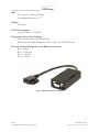
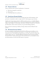
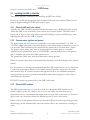
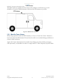
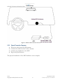
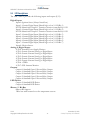
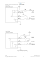
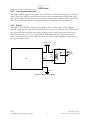
LMU-4200™ Hardware and Installation Guide Short Version June, 2001 Copyright ©CalAmp DataCom Inc 2010 CalAmp Proprietary & Confidential LMU-4200™ Hardware and Installation Guide Table of Contents Table of Contents ................................................................................................................................................... ii 1 INTRODUCTION................................................................................................................................................................................................. 1 1.1 About This Manual .......................................................................................................................................1 1.2 About the CalAmp Location Messaging Unit-4200™ (LMU-4200™)......................................................2 1.2.1 Environmental Specifications ................................................................................................................2 1.3 LMU-4200™Connectors...............................................................................................................................4 1.3.1 Power Connector ...................................................................................................................................5 1.3.2 I/O Connector ........................................................................................................................................6 1.3.3 Serial Interface Connectors....................................................................................................................7 1.3.4 Expansion Interface ...............................................................................................................................8 1.4 GPS Receiver ...............................................................................................................................................10 1.5 RF Connector...............................................................................................................................................10 1.6 Available Radio Interfaces .........................................................................................................................10 2 INSTALLING THE LMU .................................................................................................................................................................................... 11 2.1 Preparing for Installation ...........................................................................................................................11 2.2 Plan The Installation ...................................................................................................................................12 2.2.1 Size and Placement of LMU Unit........................................................................................................12 2.2.2 Placement of Antennas ........................................................................................................................13 2.2.3 Comm Antenna Placement Guidelines ................................................................................................13 2.2.4 GPS Antenna Placement Guidelines....................................................................................................13 2.2.5 Access to the SIM (Subscriber Identity Module) Card ........................................................................14 2.2.6 Protection from Heat............................................................................................................................14 2.2.7 Visibility of Diagnostic LEDs .............................................................................................................14 2.2.8 Cable Length........................................................................................................................................15 2.2.9 Moisture and Weather Protection ........................................................................................................15 2.2.10 Preventing Accidental or Unauthorized Modification ....................................................................15 2.3 Installing the LMU in a Vehicle .................................................................................................................16 2.3.1 Place the LMU unit in the vehicle. ......................................................................................................16 2.3.2 Connect power, ignition, and ground...................................................................................................16 2.3.3 Place the GPS antenna. ........................................................................................................................16 2.3.4 Mount the Comm. Antenna. ................................................................................................................17 2.3.5 Typical Connection Sequence..............................................................................................................18 2.4 I/O Descriptions...........................................................................................................................................20 2.4.1 Ignition and Inputs...............................................................................................................................21 2.4.2 3-Axis Accelerometer Input.................................................................................................................23 2.4.3 Outputs.................................................................................................................................................23 2.4.4 Status LEDs .........................................................................................................................................24 Verification via SMS .........................................................................................................................................25 V1.0.9 Copyright ©CalAmp DataCom Inc 2010 - ii - November 13, 2010 CalAmp Proprietary & Confidential LMU-4200™ Hardware and Installation Guide 1 Introduction Welcome to the LMU-4200™ Hardware and Installation Guide. This manual is intended to provide information on the basic setup and installation of the CalAmp LMU-4200™ product including hardware descriptions, environmental specifications, wireless network overviews and device installation. 1.1 About This Manual The LMU-4200™ is one of the most flexible and economical mobile tracking hardware products available. In order to accurately describe the functionality of these units we have broken this manual into the following sections: System Overview: A basic description of a CalAmp LMU-4200™ based tracking system. This includes a description of roles and responsibilities of each of the CalAmp components as well as a brief overview of the wireless data technologies used by the LMU-4200™. Hardware Overview: Describes the physical characteristics and interfaces of the LMU-4200™. Installation and Verification: Provides guidance for the installation of the LMU4200™ in a vehicle and instructions on how to verify the installation is performing adequately. V1.0.9 Copyright ©CalAmp DataCom Inc 2010 -1- November 13, 2010 CalAmp Proprietary & Confidential LMU-4200™ Hardware and Installation Guide 1.2 About the CalAmp Location Messaging Unit-4200™ (LMU-4200™) CalAmp's flagship LMU-4200™ product has the features, expandability, and flexibility with the intelligence to meet all customers’ ever changing needs in fleet management. The LMU4200™ offers a full set of features, comprehensive I/O system and expandable accessories that make it an industry leading value proposition. The LMU-4200™ expandability and flexibility lowers the cost of delivering, supporting, and growing fleet management solutions. The LMU-4200™ is designed to support customers needing an array of vehicle interfaces. For example, the serial ports supply switchable power at selectable voltages to ease the installation of peripheral data devices. The optional jPOD™ ECU (Engine Control Unit) interface reads and transmits heavy-duty engine condition and performance data such as engine temperature along with the fault codes to provide the best possible real-time picture of vehicle health. In addition, the LMU-4200™ offers optional WiFi and Bluetooth capabilities. The LMU-4200™ also incorporates CalAmp's industry leading over-the-air device management and maintenance system software, , PULS™ (Programming, Updates, and Logistics System). Configuration parameters, PEG rules, and firmware can all be updated over the air. Our web-based maintenance server, PULS™ scripts, and firmware, can all be updated over-the-air. PULS™ offers out-of-the-box hands free configuration and automatic post-installation upgrades. You can also monitor unit health status across your customers' fleets to quickly identify issues before they become expensive problems. 1.2.1 Environmental Specifications The LMU-4200™ is designed to operate in environments typically encountered by fleet vehicles, including wide temperature extremes, voltage transients, and potential interference from other vehicle equipment. To ensure proper operation in such an environment, the LMU-4200™ was subjected to standard tests defined by the Society of Automotive Engineers (SAE). The specific tests included temperature, shock, vibration, and EMI/EMC. These tests were performed by independent labs and documented in a detailed test report. In accordance with Appendix A of SAE J1113 Part 1, the Unit is considered a “Functional Status Class B, Performance Region II” system that requires Threat Level 3 Testing. The following shows the environmental conditions the LMU is designed to operate in and the relevant SAE tests that were performed. No formal altitude tests were conducted. Size 4.8" long x 3.3" wide x 0.85" high Weight 11 ounces. Operating Temperature V1.0.9 Copyright ©CalAmp DataCom Inc 2010 -2- November 13, 2010 CalAmp Proprietary & Confidential LMU-4200™ Hardware and Installation Guide -30o C to 70o C Storage Temperature Range: -40o C to 85o C Humidity 0% to 95% relative humidity, non-condensing Shock and Vibration Ground vehicle environment with associated shock and vibration SAE Test: SAE J1455 Mil Standard 202G and 810F Electromagnetic Compatibility (EMC) EMC compliant for a ground vehicle environment SAE Test: SAE J1113 Parts 2, 12, 21 and 41 Operating Voltage Range The LMU-4200™ supports vehicles with 12 or 24 VDC systems including transients and electrical system noise; this includes ranges from 6 to 32 VDC. Electrostatic Discharge (ESD) No damage or performance degradation after the ESD disturbance. SAE Test: SAE J1113 Part 13 Power Consumption Average: 70mA at 13.8 VDC Deep Sleep: 4mA Sleep on Network (SMS): 10mA Sleep on Network (GPRS): 20mA V1.0.9 Copyright ©CalAmp DataCom Inc 2010 -3- November 13, 2010 CalAmp Proprietary & Confidential LMU-4200™ Hardware and Installation Guide 1.3 LMU-4200™Connectors The LMU-4200™ offers 5 connectors to access power, I/O, serial communications and other expansion capabilities. These connectors are: Primary Power Connector I/O Connector Serial Port Connector – Host/Aux1 Serial Port Connector – Aux 2 Expansion Connector Figure 1 - LMU-4200™ Connectors V1.0.9 Copyright ©CalAmp DataCom Inc 2010 -4- November 13, 2010 CalAmp Proprietary & Confidential LMU-4200™ Hardware and Installation Guide 1.3.1 Power Connector The LMU-4200™ uses a 4 pin Molex 43045-0402 connector as its power connection. The pin out is as follows: Pin 1 2 3 Signal Name VIN GND INPUT 0 4 ADC1 Description Power Ground Input 0 / Ignition Sense – Digital Input Analog to Digital Input 1 Input or Output Power / Input Ground Input Input Figure 2 - LMU-4200™ Header (looking into LMU) CalAmp offers a fused, 4-wire, 8 foot harness that mates to this connector (Part Number 5C888) V1.0.9 Copyright ©CalAmp DataCom Inc 2010 -5- November 13, 2010 CalAmp Proprietary & Confidential LMU-4200™ Hardware and Installation Guide 1.3.2 I/O Connector The LMU-4200™’s features expanded I/O capabilities via its 22-Pin Molex 43045-2202 connector. Its pin-out is as follows: Pin 1 2 3 4 5 6 7 8 9 10 11 12 13 14 15 16 17 18 19 20 21 22 Signal Name Input 1 Input 2 Input 3 Input 4 Input 5 Input 6 Input 7 1BB T Data 1BB GND 1 BB R Data 1 BB Gnd Output 0 Output 1 Output 2 Output 3 Output 4 LED 1 LED 2 ADC 2 ADC 3 ADC 4 ADC 5 Description Input 1 – Digital Input Input 2 – Digital Input Input 3 – Digital Input Input 4 – Digital Input Input 5 – Digital Input Input 6 – Digital Input Input 7 – Digital Input 1 Bit Bus Data (T) 1 Bit Bus Ground 1 Bit Bus Data (R) 1 Bit Bus Ground Standard Cable Color Blue Orange Violet Gray Green & White Blue & White Black & White Green & Black Black Orange & Black Black Green Brown Yellow Blue & White & Orange Green & Black & Orange Red & Green Orange & Green Black & Red White & Red Orange & Red Blue & Red Input or Output Input Input Input Input Input Input Input Input/Output Ground Input/Output Ground Output Output Output Output Output Output Output Input Input Input Input Figure 3 - LMU-4200™ Header (looking into LMU) CalAmp offers a 6”, 20 wire harness assembly for this connector (Part Number5C889) V1.0.9 Copyright ©CalAmp DataCom Inc 2010 -6- November 13, 2010 CalAmp Proprietary & Confidential LMU-4200™ Hardware and Installation Guide 1.3.3 Serial Interface Connectors The LMU-4200™ offers 2 serial interface connections (Host/Aux1 and Aux 2) on its front face. These are provided via 2 Molex 43650-0501 connectors using the following pin outs. Pin 1 2 3 4 5 Signal Name VIN_FILT VCC3V3 Ground TX RX Description Filtered LMU Power 3.3V Power Ground Transmit Data Receive Data Input or Output Power Supply Power Supply Ground Input to LMU Output From LMU Figure 4 – Serial Interface Connector Users should only use CalAmp approved serial adapters with these connections. (Part Number 133337-5 and 133564-1) Figure 5 - LMU-4200™ Serial Cable Plugged into Aux 1 V1.0.9 Copyright ©CalAmp DataCom Inc 2010 -7- November 13, 2010 CalAmp Proprietary & Confidential LMU-4200™ Hardware and Installation Guide 1.3.4 Expansion Interface The expansion interface located on the back of the LMU-4200™ via the 16-in Molex connector is used to extend I/O functions and provide serial access to the LMU-4200™. It should only be used with CalAmp expansion harnesses. The available accessories are: 1.3.4.1 jPOD™ Vehicle Bus Adaptor The CalAmp jPOD Adapter is a J1939 compliant device that reads the parameters broadcast in the J1939 bus, processes them and provides filtered vehicle data to the LMU-4200™. A script is written using a special software tool and loaded into the jPOD. This script defines the specific parameters (PGNs/SPNs) to read, how to process them and how to send them to the host. The script does not send any requests onto the bus. Selected J1939 Parameters Battery Potential / Power Input 1 Engine Coolant Temperature Engine Speed RPM Vehicle Speed Accelerator Pedal Position % Brake Pedal Switch - On/Off Total Vehicle Distance Engine Total Fuel Used Diesel Particulate Filter Status DM1 (Diag Msg 1 - active DTC’s) V1.0.9 Copyright ©CalAmp DataCom Inc 2010 -8- PGN SPN 65271 168 65262 110 61444 190 65265 84 61443 91 65265 597 65248 245 65257 250 64892 3701 65226 November 13, 2010 CalAmp Proprietary & Confidential LMU-4200™ Hardware and Installation Guide Size 3.5" long x 1.7" wide x 0.9" high Total length with cable: 12.7” Weight 2.3 ounces Power Consumption Average: 70mA at 13.8 VDC Diagnostic tools used by CalAmp: J1939 simulator from oZen Electronics J1939 Scan from OBD Diagnostics, INC - http://www.j1939scan.com Pin outs for the J1939 signals on the DE15 pin connector: Pin 1 - Power Pin 2 - CAN Low Pin 3 - CAN Hi Pin 15 - GND Figure 6 jPOD™ Vehicle Bus Adaptor V1.0.9 Copyright ©CalAmp DataCom Inc 2010 -9- November 13, 2010 CalAmp Proprietary & Confidential LMU-4200™ Hardware and Installation Guide 1.4 GPS Receiver 50 channel GPS receiver (with SBAS, DGPS) Accuracy: 2 meter CEP (with SBAS) Antenna connector: SMA Tracking Sensitivity: -160dBm Acquisition Sensitivity: -144dBm Note that the CalAmp LMU-4200™ requires an antenna amplifier that operates at 3VDC; 5VDC amps will not work. 1.5 RF Connector LMU-4200’s™ uses an SMC connector with a 50 Ω iimpedance. 1.6 Available Radio Interfaces CDMA 1xRTT – Bell Mobility ( Part Number: LMU42C1B1-G1000) CDMA 1xRTT – Sprint ( Part Number: LMU42C1S1-G1000) CDMA 1xRTT – Verizon Wireless ( Part Number: LMU42C1V1-G1000) GPRS (Part Number: LMU42G101-G1000) HSPA (Part Number: LMU42GH101-G1000) V1.0.9 Copyright ©CalAmp DataCom Inc 2010 - 10 - November 13, 2010 CalAmp Proprietary & Confidential LMU-4200™ Hardware and Installation Guide 2 Installing the LMU The installation of the LMU and its antennas can have a major impact on the LMU’s performance. It is recommended that installers be familiar with the installation of GPS and cellular devices and are comfortable in a vehicle environment. 2.1 Preparing for Installation Be sure you have received all the LMU components you need. This must include: The LMU to be installed A power harness GPS Antenna Comm Antenna Optional Components: o Input and output cables o Relays o LMU peripherals (i.e. Serial adapter, ioPOD, BTA, TetheredLocator) o Host serial devices (e.g. PDAs, laptops, other serial devices) V1.0.9 Copyright ©CalAmp DataCom Inc 2010 - 11 - November 13, 2010 CalAmp Proprietary & Confidential LMU-4200™ Hardware and Installation Guide 2.2 Plan The Installation Verify Power, Ground and Ignition. Be sure to check each source (power, ground and ignition) to ensure that the proper signaling exists. This is typically accomplished with a multi-meter. Before drilling any holes or running any wires, decide where each hardware component will be located (LMU, antennas, peripherals, etc.). Be sure that the cables to the LMU are not bent or constricted in any way. Also make sure that the LMU is kept free from direct exposure to the elements (sun, heat, rain, moisture etc...). Be advised that an installation that violates the environmental specifications of the LMU will void the warranty. The best way to ensure a trouble-free installation is to consider your options and make some decisions before you start. Take a look at the vehicle and determine how to best install the LMU for the following purposes: Accurate data gathering and simulation of how customers actually use your solution Ongoing monitoring and maintenance of LMU equipment Accidental or intentional alteration of the equipment or cable connections The following sections cover some of the issues to consider when planning your LMU installation. 2.2.1 Size and Placement of LMU Unit The dimensions of the LMU should be taken into account, particularly when installing in a vehicle: Whether you intend to place the LMU under a seat or into a cavity behind the vehicle’s interior molded trim, be sure the LMU will fit before drilling any holes or running cable Be certain that the cables running to the LMU will not be bent or constricted. Damage to the cables may impede the LMU’s performance. Be certain that the installation point will not violate any of the LMU’s environmental specification (temperature, moisture, etc…) as improper installation of the LMU may void the warranty. See the LMU Environmental Specifications for the exact measurements and specifications of the LMU-4200™. Typical installations will place the LMU under the vehicle dash board, or in the trunk. Make sure you can get access to the unit afterwards as under some circumstances it may be necessary to add additional wiring or connections to the LMU. V1.0.9 Copyright ©CalAmp DataCom Inc 2010 - 12 - November 13, 2010 CalAmp Proprietary & Confidential LMU-4200™ Hardware and Installation Guide 2.2.2 Placement of Antennas There are effectively three options for placements of an antenna: Roof-mount (magnetic or thru-hole) Glass-mount Covert (e.g. under the seat, dash, etc…) 2.2.3 Comm Antenna Placement Guidelines The Comm. Antenna must be located at least 20cm away from vehicle passengers, other personnel, or bystanders in order to comply with FCC radio frequency exposure limits. Typically, the Comm antenna used by the LMU for wireless service is a standard 3-dB gain whip. It mounts with standard mounts (i.e. thru-hole, magnetic mount or peel and stick) and requires a ground plane to work properly. If possible, it should be located at least 3 feet from the GPS antenna. Ensure that the cable does not get crushed during installation. Please note that the antennas provided by CalAmp combine both the GPS and Comm portions. 2.2.4 GPS Antenna Placement Guidelines In order to maximize the performance of the LMU the GPS antenna should have a clear view of the sky. When installing the GPS antenna on a vehicle, make sure that there are no obstructions close to the antenna that might block the view 360 to the horizon. Things like air horns, lights, vents, etc… should not block the antenna beyond 5 above the horizon. The best location is usually near the center of the roof; however it is also desirable to locate the cellular antenna as far from the GPS antenna as is practical. V1.0.9 Copyright ©CalAmp DataCom Inc 2010 - 13 - November 13, 2010 CalAmp Proprietary & Confidential LMU-4200™ Hardware and Installation Guide 7 Examples of good and poor GPS antenna placements The received signal levels at the GPS antenna from the satellites are very low in power (approximately -136 dBm), so any blockage of the antenna can affect the quality of the location computed by the receiver. Kinks or tight knots in the antenna cable can also prevent the GPS receiver from operating properly. When laying out the antenna cable, care should be taken so that the cable is not subjected to crushing or strain. 2.2.5 Access to the SIM (Subscriber Identity Module) Card When used in a GSM or HSPA network, each LMU uses a Subscriber Identity Module (SIM) card, which should be inserted before you install the LMU for the first time. The SIM card is attached to the main-board inside the housing of the LMU unit. At some future time, you might need or want to replace the SIM card with a different one, so try to install the LMU in such a way that the cover can be removed to make the SIM card accessible. 2.2.6 Protection from Heat It is best not to place the LMU unit in an unusually warm location such as directly near heater vents, near hot engine components or in direct sunlight. The maximum temperature that can be tolerated by the LMU is described in the LMU Environmental Specifications section. 2.2.7 Visibility of Diagnostic LEDs Status LED lights on the front of the LMU unit can provide valuable information about the operation of the LMU. When feasible, attempt to install the LMU in such a way that these lights can be seen with reasonable ease. V1.0.9 Copyright ©CalAmp DataCom Inc 2010 - 14 - November 13, 2010 CalAmp Proprietary & Confidential LMU-4200™ Hardware and Installation Guide You may find it useful to be able to view the LEDs periodically to make sure that the LMU is operating properly. If at any time you should encounter a problem with the LMU, you may need to read the LEDs in order to troubleshoot the problem. If you cannot fix the LMU yourself, you will need to provide the LED information to CalAmp customer support. For information about how to interpret the LEDs, see the Status LED Behavior section. 2.2.8 Cable Length The RF cables which are provided for connecting to the LMU antennas should be used at the length provided. Do not cut cables. Instead, coil any excess cable length, making sure not to crimp or flatten the antenna cable. 2.2.9 Moisture and Weather Protection The LMU unit must be located where it will not be exposed to moisture or water. In a typical installation inside a vehicle this is not commonly thought to be a concern; however, it might be best to avoid locating the LMU below a car’s cup holders, or where rain might easily splash into the compartment when a door is opened. 2.2.10 Preventing Accidental or Unauthorized Modification If you anticipate that fleet drivers or others might interfere with the LMUs once they are installed, take steps to be sure that it is not easy to disconnect the antenna wiring, remove the LMU from its power source, etc. Two common methods are the use of Tamper Proof Sealant or creation of PEG Script to detect power loss or GPS antenna disconnections. V1.0.9 Copyright ©CalAmp DataCom Inc 2010 - 15 - November 13, 2010 CalAmp Proprietary & Confidential LMU-4200™ Hardware and Installation Guide 2.3 Installing the LMU in a Vehicle This section provides instructions for installing an LMU in a vehicle. Be sure to consider the design decisions described in the previous sections. When you are ready to begin installing the LMU, follow these steps: 2.3.1 Place the LMU unit in the vehicle. Typically, the LMU should be placed under the passenger seat or dashboard of the vehicle. Attach the LMU to the solid body of the vehicle, not to plastic panels. The LMU can be placed out of sight by removing interior trim and molding to expose available space, then replacing the trim once the LMU is in place. 2.3.2 Connect power, ignition, and ground. The power input (red wire) must be connected to a constant (un-switched) +12 VDC or +24 VDC supply; preferably, connected directly to the vehicle battery terminal or as close to it as possible. This connection point should be fuse protected to not more than 5 Amps. The ignition input (white wire) must be connected to the vehicle ignition or another appropriate key operated line, such as ACCESSORY, ensuring that power to the ignition wire is available only when the vehicle ignition is on. The ground line (black wire) must be connected to chassis ground. Failure to connect these lines in the manner described may result in discharge of the vehicle battery. For best results, it is strongly recommended that the LMU connection be on its own circuit. Connect the power input directly to the vehicle battery if possible and protect the circuit with an inline fuse. If you must connect through the fuse box, use standard commercial wiring practices to create a permanent installation rather than using press-in fuse clips or other temporary measures. DO NOT connect the power cable to the LMU at this time. 2.3.3 Place the GPS antenna. The GPS antenna must have a clear view of the sky. Mount the GPS antenna on the vehicle’s highest point (for example, the roof of a car). Make sure that there are no obstructions close to the antenna that might block the view 360° to the horizon. Air horns lights, vents, etc.. should not block the antenna beyond 5° above the horizon. Kinks or knots in the antenna cable can prevent the GPS receiver from operating properly. When laying out the antenna cable, take care that the cable is not subjected to crushing or strain. V1.0.9 Copyright ©CalAmp DataCom Inc 2010 - 16 - November 13, 2010 CalAmp Proprietary & Confidential LMU-4200™ Hardware and Installation Guide The ideal location is typically near the center of the vehicle’s roof. However, it is also desirable to locate the cellular antenna as far from the GPS antenna as possible. Figure 8 - GPS Antenna Location 2.3.4 Mount the Comm. Antenna. When using separate Comm and GPS antennas, it is best to locate the Comm. Antenna at least 3 feet from the GPS antenna. Ensure that the cable is not crushed during installation or normal vehicle operation. Again, the Comm. Antenna must be located at least 20cm away from vehicle passengers, other personnel, or bystanders in order to comply with FCC radio frequency exposure limits. V1.0.9 Copyright ©CalAmp DataCom Inc 2010 - 17 - November 13, 2010 CalAmp Proprietary & Confidential LMU-4200™ Hardware and Installation Guide Figure 9 - Window Mount Antenna Location 2.3.5 Typical Connection Sequence Attach the cable from the GPS antenna. Connect the cable from the Comm.. antenna Connect any peripherals to the LMU Plug in the power harness. The physical installation of the LMU hardware is now complete. V1.0.9 Copyright ©CalAmp DataCom Inc 2010 - 18 - November 13, 2010 CalAmp Proprietary & Confidential LMU-4200™ Hardware and Installation Guide Figure 10 - Completed Install V1.0.9 Copyright ©CalAmp DataCom Inc 2010 - 19 - November 13, 2010 CalAmp Proprietary & Confidential LMU-4200™ Hardware and Installation Guide 2.4 I/O Descriptions The LMU-4200™ provides the following inputs and outputs (I/O): Digital Inputs Input 0: Ignition Sense (Always biased low) Input 1: Generic Digital Input (Biased high or low/ S-158 Bit 1) NOTE: Shared with Output 1. Function selection controlled by S-159 Input 2: Generic Digital Input (Biased high or low/ S-158 Bit 2) NOTE: Shared with Output 2. Function selection controlled by S-159 Input 3: Generic Digital Input (Biased high or low/ S-158 Bit 3) Input 4: Generic Digital Input (Biased high or low/ S-158 Bit 4) Input 5: Generic Digital Input (Biased high or low/ S-158 Bit 5) Input 6: Generic Digital Input (Biased high or low/ S-158 Bit 6) Input 7: Generic Digital Input (Biased high or low/ S-158 Bit 7) Input 8: Motion Sensor Analog to Digital Inputs A/D 0: External Power Supply Monitor A/D 1: Generic External Analog to Digital Input A/D 2: Generic External Analog to Digital Input A/D 3: Generic External Analog to Digital Input A/D 4: Generic External Analog to Digital Input A/D 5: Generic External Analog to Digital Input A/D 6: <TBD> A/D 7: GPS Antenna Monitor Outputs: Output 0: Standard Open Collector Relay Output Output 1: Standard Open Collector Relay Output Output 2: Standard Open Collector Relay Output Output 3: Standard Open Collector Relay Output Output 4: Standard Open Collector Relay Output LED Drivers Output 5: Standard LED Driver Output 6: Standard LED Driver iButton / 1 Bit Bus iButton ID Support 1Wire bus with current boost for temperature sensors V1.0.9 Copyright ©CalAmp DataCom Inc 2010 - 20 - November 13, 2010 CalAmp Proprietary & Confidential LMU-4200™ Hardware and Installation Guide 2.4.1 Ignition and Inputs The LMU-4200™ provides up to 4 inputs on its own and up to 7 with the ioPOD. These inputs are protected from typical vehicle transients and can be directly connected to most vehicle level logical inputs from 4 volts up to the vehicle power input level (typically 12 VDC). Their input impedance is approximately 10k. One of these inputs is dedicated to sensing the vehicle’s ignition status to provide for flexible power management. The other two inputs may be used to sense vehicle inputs such as cooling unit operation, a hidden driver “Panic” switch, taxi on-duty/off-duty meter status or many others. The ignition input is pulled to ground through the 10k resistance, where the other inputs can be configured to be normally High (i.e. pulled to +12v through a 10k resistor) or Low (i.e. pulled to ground through a 10k resistor). The diagrams below show how to connect the inputs in both a high- and low-biased configuration: V1.0.9 Copyright ©CalAmp DataCom Inc 2010 - 21 - November 13, 2010 CalAmp Proprietary & Confidential LMU-4200™ Hardware and Installation Guide Figure 11 - Sample Input Wiring V1.0.9 Copyright ©CalAmp DataCom Inc 2010 - 22 - November 13, 2010 CalAmp Proprietary & Confidential LMU-4200™ Hardware and Installation Guide 2.4.2 3-Axis Accelerometer Input The LMU-4200™ supports an internal 3 Axis Precision Accelerometer as one of its discreet inputs. When the LMU is moved in any direction, the associated input will be in the High state. If the LMU’s accelerometer does not detect motion, then the input will be in the Low state. No external connections are required for this functionality to be operational. 2.4.3 Outputs The LMU’s and ioPOD;s outputs are designed to drive external relays. These outputs provide a high-current, open-collector driver that can sink up to 150 mA each. These drivers may be used to drive external relays that can then control vehicle functions such as door locks, fuel shut-off valves, sirens and lights. If additional current is required to drive the relays, external circuitry can be added to source the current. This diagram is a typical use of an output to drive a relay. Vehicle Power (+12VDC) Relay 86 87 Relay Contacts Relay Coil LMU 30 Output 0 85 Ground Figure 12 - Sample Relay Wiring V1.0.9 Copyright ©CalAmp DataCom Inc 2010 - 23 - November 13, 2010 CalAmp Proprietary & Confidential LMU-4200™ Hardware and Installation Guide 2.4.4 Status LEDs The LMU-4200™ is equipped with two Status LEDs, one for GPS and one for COMM (wireless network status). The LEDs use the following blink patterns to indicate service: LED #1 (Comm LED - Orange) Definitions Condition Modem Off Comm On - Searching Network Available Registered but no Inbound Acknowledgement Registered and Received Inbound Acknowledgement LED 1 Off Slow Blinking Fast Blinking Alternates from Solid to Fast Blink every 1s Solid LED #2 (GPS LED - Yellow) Definitions Condition GPS Off GPS On GPS Time Sync GPS Fix V1.0.9 Copyright ©CalAmp DataCom Inc 2010 LED 1 Off Slow Blinking Fast Blinking Solid - 24 - November 13, 2010 CalAmp Proprietary & Confidential LMU-4200™ Hardware and Installation Guide Verification via SMS The current Comm, GPS and Inbound status of either a CDMA or GSM LMU can be obtained via SMS provided you have access to an SMS capable phone or PDA. Using your handset, send the following SMS Message to the LMU: !R0 Within a few minutes, the LMU should return a response in the following format: APP: <App ID> <Firmware Version> COM:<RSSI> [./d/D][./a/A][./L][IP address] [<APN>] GPS:[Antenna <Short/Open/Off>] | [No Time Sync] | [<FixStatus> <Sat Count>] INP:<inputs states> <vehicle voltage> MID:<mobile ID> <mobile ID type> INB:<inbound IP address>:<inbound port> <Inbound Protocol (LMD/LMX)> APP: o <App ID>: The Application ID value of the LMU indicating the host platform and the wireless networking technology of the LMU. o <Firmware Version>: The current firmware version in use by the LMU COM: o <RSSI>: This is the signal strength the wireless modem sees from the network. In general the LMU is at least scanning for the network if the RSSI is not -113. o [./d/D]: If the character ‘D’ is present, it indicates the LMU had a data session established when it responded to the status request. For the 8-Bit product line an upper case ‘D’ indicates both the Inbound and Maintenance sockets are ready. The lower case ‘d’ indicates that only the Maintenance socket is ready. A ‘.’ indicates no sockets are ready. o [./a/A]: This field indicates if the LMU has received an Acknowledgement from the Inbound server. This field will be empty if the LMU has never received an ACK.The lower case ‘a’ will be present if it has received an ACK since the last cold boot (i.e. power cycle) but not the last warm boot (App Restart or Sleep). The upper case ‘A’ will be present if the LMU has received an ACK since the last warm boot. A ‘.’ Indicates no acknowledgement has been received. V1.0.9 Copyright ©CalAmp DataCom Inc 2010 - 25 - November 13, 2010 CalAmp Proprietary & Confidential LMU-4200™ Hardware and Installation Guide o [./L]: This field indicates if the LMU’s log is currently active. An ‘L’ indicates that the log is currently in use (i.e. one or more records have been stored) where a ‘.’ indicates the log is inactive. o [IP Address]: This is an optional field if and is only present if the LMU has established a valid data session. This field will contain the current IP address of the LMU as assigned by the wireless network. Note that if you see a value of 192.168.0.0, this is an indication that the LMU has not been able to establish a data session. o [<APN>] The current Access Point Name in use by a GSM LMU. GPS: o [Antenna <Short/Open/Off>]: This field, if present, indicates a problem with the LMU’s GPS antenna. A value of Short indicates that the antenna cable has likely been crushed. A value of Open indicates that the antenna cable is either cut or disconnected. A value of Off indicates that the LMU’ GPS receiver is off. o [No Time Sync]: If this field is present, it indicates that the LMU’s GPS receiver has not been able to find even a single GPS satellite. This would likely been seen in conjunction with the above antenna error, or if the LMU GPS antenna is otherwise blocked1. o [<FixStatus> <Sat Count>]: If these fields are present it indicates that the LMU has, or had a valid GPS solution. The <Sat Count> field indicates how many GPS satellites are currently in use by the LMU. The <FixStatus> field indicates the type of fix. The Fix Status types are detailed in the LM Direct Reference Guide. INP: o <input states>: This field details the current state of each of the LMU’s discreet inputs. This field is always 8 characters long. The left most character represents the state of input 7 where the right most represents the state of input 0 (i.e. the ignition). A value of 1 indicates the input is currently in the high state. A value of 0 indicates it is currently in the low state. o <vehicle voltage>: This field will contain the current reading of the LMU’s internal A/D. This will be the supply voltage provided to the LMU in mV. MID: o <mobile ID>: This will be the current mobile ID in use by the LMU. 1 For example you may see this if the vehicle is in a garage when the LMU is powered up. V1.0.9 Copyright ©CalAmp DataCom Inc 2010 - 26 - November 13, 2010 CalAmp Proprietary & Confidential LMU-4200™ Hardware and Installation Guide o <mobile ID type>: This will be the type of Mobile ID in use by the LMU. The available types are, Off, ESN, IMEI, IMSI, USER, MIN and IP ADDRESS. INB: o <inbound IP address>: This is the current IP address in use by the LMU. This value should match the IP address of your LM Direct server. o <inbound port>: This is the current UDP port the LMU will use to deliver its LM Direct data. This value should match UDP port you are using on your LM Direct server. It is typically 20500. o <Inbound Protocol (LMD/LMX)>: This is the current UDP/IP messaging protocol in use by the LMU. In general it should be LMD. Example CDMA Response: APP:082 8.3d COM:-81 D A 10.73.72.105 GPS:3D-INVLD 0 INP:11100111 13.6V MID:4141000100 ESN INB:207.7.101.227:20500 LMD Example GSM Response APP:081 8.3d COM:0 GPS:No Time Sync INP:11100111 13.7V MID:4141000100 ESN INB:207.7.101.227:20500 LMD V1.0.9 Copyright ©CalAmp DataCom Inc 2010 - 27 - November 13, 2010 CalAmp Proprietary & Confidential