1
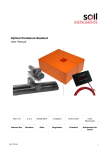
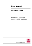
User Manual SXP-500 Read this guide thoroughly and follow the installation and operation procedures carefully in order to prevent any damage to the units and/or any devices that connect to them. This package contains: M 1 Bidirectional Serial/Parallel Converter (SXP-500) M 1 User Manual If anything is damaged or missing, contact your dealer. © Copyright 2000 ATEN International Co., Ltd. Manual Part No. PAPE-1154-100 Printed in Taiwan 10/1999 All brand names and trademarks are the registered property of their respective owners. 2001 - 01 -10 Overview The SXP-500 is an interface converter that allows Centronics and RS-232 devices to communicate with each other (a computer with an RS-232 output to a Centronics printer, for example) The SXP-500 provides a DB-9 RS-232C (DCE) compatible connector, and a C-36 Centronics connector. The serial baud rate is from 1200 to 115200 bps., selectable by a combination of DIP Switch and Jumper settings. The parallel interface speed is 92.16 KB/sec. The unit supports both hardware and software (XON/XOFF) handshaking. Setup is extremely easy. All that is involved is setting the DIP Switch, Jumper (JP1), and connecting the cables. Features M M M M Both Hardware and XON/XOFF Handshaking Non-powered Easy Installation Compact Size Front View Serial Port Connector Power LED 1.8m Parallel Port Connector -1- 2001 - 01 -10 Rear View DIP Switch DIP Switch Configuration Overview: The SXP-500 is configured by setting an eight segment DIP Switch as follows: Switch Purpose 1 2 3 Baud rate Setting 4 Handshake Setting 5 Data and Stop Bits Setting 6 7 Parity Setting 8 Conversion Direction setting An explanation of each DIP Switch setting is given in the next section. Note: 1. When the segment is set in the direction of the arrow, it is ON. 2. In each table, the default setting is highlighted. -2- 2001 - 01 -10 DIP Switch Settings Baud Rate: The baud rate is set with DIP Switch segments 1 - 3 (located on the bottom panel), and JP1 (located inside the housing), as shown in the table, below: DIP Switch Segment Baud Rate (bps) 1 2 3 JP1 Short JP1 Open ON ON ON 1200 38400 ON ON OFF 2400 57600 ON OFF ON 9600 76800 115200 ON OFF OFF 14400 OFF ON ON 19200 153600 OFF ON OFF 38400 230400 OFF OFF ON 57600 460800 OFF OFF OFF 115200 921600 Data and Stop Bits: Handshake: Segment Segment Handshake Data Bits Stop Bits 5 4 ON XON / XOFF ON 7 2 OFF Hardware OFF 8 1 Parity: Conversion Direction: Segment Segment Parity 6 7 Direction 8 ON Either Parity Inhibit ON Parallel to Serial OFF ON Even Parity OFF Serial to Parallel OFF OFF Odd Parity -3- 2001 - 01 -10 Cabling Serial to Parallel: When performing a Serial to Parallel interface conversion: 1. Plug the attached serial cable (with DB 9 female connector) leading out of the SXP-500 into the PC’s serial port 2. Plug the female end of a C-36 male/female printer cable into the SXP-500’s printer connector 3. Plug the male end of the C-36 male/female printer cable into the printer. Note: If the distance to the printer is close enough, you can plug the SXP-500 directly into the printer, without the need for a printer cable. -4- 2001 - 01 -10 Parallel to Serial: When performing a Parallel to Serial interface conversion: 1. Use an IEEE1284 Parallel cable with a male D25 connector at one end, and a female C-36 connector at the other: a) Plug the D25 end of the cable into the PC’s parallel port b) Plug the C-36 end of the cable into the SXP-500’s Centronics connector 2. Use a serial cable with a male D9 connector at one end, and a male D25 connector at the other: a) Plug the D9 end of the cable into the SXP-500’s attached serial cable. b) Plug the D25 end of the serial cable into the printer’s serial port. -5- 2001 - 01 -10 Serial Port Cabling: Device Connector’s Pin # DCE DTE DCE DTE DB-9 DB-9 DB-25 DB-25 2 3 3 2 3 2 2 3 8 7 5 4 7 8 4 5 4 6 20 6 6 4 6 20 5 5 7 7 Cables a 25-pin/25-pin cable or a 9-pin/25-pin cable Tx Rx Rx Tx RTS CTS CTS RTS DSR DTR DTR DSR GND GND SXP-500 DCE DB-9 3 2 7 8 6 4 5 Parallel Port Cabling: Device’s Pin # DB-25 C-36 1 1 2-9 2-9 10 10 11 11 12 12 13 13 14 14 15 32 16 31 17 36 18-25 19-30 a 25-pin/36-pinCables or a 36-pin/36-pin cable STROBE D0-D7 ACK BUSY PE SLCT AUTOFEED-XT ERROR INIT SLCT-IN GND -6- 2001 - 01 -10 SXP-500 C-36 1 2-9 10 11 12 13 14 32 31 36 19-30 Operation When operating the SXP-500, please take note of the following: 1. Since the SXP-500 is a DCE device, the serial device it connects to must be configured as a DTE device. 2. In DCE mode, the unit uses RTS/DTR (pins 6 and 8) handshaking. When RTS/DTR is set High, the computer is allowed to transmit data. When the unit is busy, it sets the RTS/DTR line to Low, and the computer stops transmitting data. Consequently, if the computer can not identify the RTS/DTR signal, it may result in data loss. 3. The unit’s baud rate, data length, stop bits and parity settings must be configured to match those of the computer. 4. You must reset the parallel printer before printing. 5. Make sure you have set the desired Conversion Direction (with DIP switch 8). Appendix Specifications Function Specification Power Consumption AC 9V 50m A (max.) Data Transmission Distance Up to 5 m (30’) Connectors DB-9 female DCE RS-232C Centronics C-36 male Interface Exchange In Serial or Parallel Out Parallel or Serial Serial Communications Mode DCE Only LEDs Green & Red Microcontroller Temperature Humidity ASIC Operating 500 - 400C Storage -200-600C 0 -80% Housing Plastic Weight 120 g Dimensions (L x W x H) 101 x 62 x 25.5 mm -7- 2001 - 01 -10 RS-232C Interface Specification The RS-232C Interface DCE mode (default) specification is given in the table below: Pin Name Function 1 CD PULL Up (+9v) 2 TxD Transmit Data 3 RxD Receive Data 4 DSR Data Set Ready 5 GND Ground 6 DTR Data Terminal Ready 7 CTS Clear to Send 8 RTS Request to Send 9 RI Ring indicator Centronics Interface Timing Chart DATA 1 0 0.5 US (min) 0.5 US (min) 1 STB BUSY 0 0 1 ACK 0.5 US 0.25 0.5 US (min) 1 US 1 (min) 0.5 US (min) 0.25 US(min) 0 1 US (min) -8- 2001 - 01 -10 1 US (min) 1 US (min) Centronics Interface Specification Pin Name Function 1 STB DATA STROBE 2 DATA BIT 1 DATA BUS 3 DATA BIT 2 4 DATA BIT 3 5 DATA BIT 4 6 DATA BIT 5 7 DATA BIT 6 8 DATA BIT 7 9 DATA BIT 8 10 ACK DATA RECEIVED ACKNOWLEDGE 11 BUSY DEVICE BUSY OR NOT 12 PAPER EMPTY PULL UP 13 SLCT PULL UP 14 A-F PULL UP 15 N.C. 16-17 18 19-30 GROUND GROUND N.C. GROUND GROUND 31 INIT PULL UP 32 ERR PULL UP 33 GROUND GROUND 34-35 N.C. 36 SL-1 PULL DOWN -9- 2001 - 01 -10 Troubleshooting Symptom Possible Cause Action Power LED does not light Cables are not properly plugged in. Make sure that all cables are properly plugged in and fully seated in their connectors. No Data Transmission Cables are not properly plugged in. Make sure that all cables are properly plugged in and fully seated in their connectors. Cables are not properly wired Rewire the cables making sure they are correctly wired Transmitting or Terminal device has not been set Ready for data transfer. If powered Off, turn the device On. Otherwise, reset the Transmitting or Terminal device. Transmitting or Terminal Change the Transmitting or Terminal device device is in incorrect DTE to the correct DTE mode, or user’s cross mode. line. Incorrect Data Received Lines are not properly connected Rewire the cable lines to be sure they are properly connected. Incorrect serial transmission DIP Switch settings Set the DIP Switch segments to their proper settings. If the above solutions fail to alleviate the problem, contact your dealer for help. - 10 - 2001 - 01 -10 Radio & TV Interference Statement WARNING!!! This equipment generates, uses and can radiate radio frequency energy and, if not installed and used in accordance with the instruction manual, may cause interference to radio communications. This equipment has been tested and found to comply with the limits for a Class B computing device pursuant to Subpart J of Part 15 of FCC Rules, which are designed to provide reasonable protection against such interference when operated in a commercial environment. Operation of this equipment in a residential area is likely to cause interference, in which case the user at his own expense will be required to take whatever measures may be required to correct the interference. Limited Warranty IN NO EVENT SHALL THE DIRECT VENDOR’S LIABILITY EXCEED THE PRICE PAID FOR THE PRODUCT FROM THE DIRECT, INDIRECT, S P E C I A L , I N C I D E N T A L O R C O N S E Q U EN T I AL D AM AG ES RESULTING FROM THE USE OF THE PRODUCT, DISK OR ITS DOCUMENTATION. The direct vendor makes no warranty or representation, expressed, implied, or statutory with respect to the contents or use of this documentation, and specially disclaims its quality, performance, merchantability, or fitness for any particular purpose. The direct vendor also reserves the right to revise or update the device or documentation without obligation to notify any individual or entity of such revisions, or update. For further inquires please contact your direct vendor. - 11 - 2001 - 01 -10