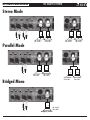
1
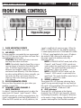
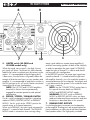
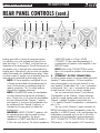
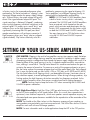
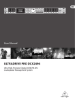
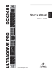
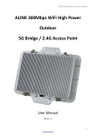
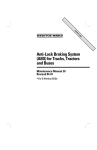
US-SERIES
THE BEAUTY OF POWER
US SERIES AMPLIFIERS
PROFESSIONAL POWER AMPLIFIERS
US-1200
US-1800
US-3000
US-4000
OWNERS MANUAL
B-52 US Series Professional Power Amplifiers - Instruction Manual
US SERIES AMPLIFIERS
THE BEAUTY OF POWER
CONTENTS
Introduction.................................................... 3
Warnings and Safety Instructions...................... 4-5
Features......................................................... 5
Power Ratings at a Glance............................... 6
US-Series Features........................................... 7
Front Panel Controls........................................ 8-9
Rear Panel Controls......................................... 10-13
Protection . .................................................... 13-15
Setup............................................................. 15-16
Connections .................................................. 17-18
Wiring . ........................................................ 19
Specifications................................................. 20
Warranty....................................................... 21
Notes............................................................ 22-23
Contact Information......................................... 24
2
B-52 US Series Professional Power Amplifiers - Instruction Manual
THE BEAUTY OF POWER
US SERIES AMPLIFIERS
WELCOME TO THE B-52 FAMILY
Thank you for purchasing a US-Series Professional Power Amplifier. At B-52, we believe in overbuilding all of our products and the US-Series Professional Power Amplifiers are no exception. We took our time in designing these stellar looking amps to outperform the competition on any stage, in the clubs and on the road. To achieve
studio quality audio reproduction we utilized low noise, low distortion circuitry and high current output stages.
We used oversized toroidial transformers and large filter capacitors to deliver super clean, fist pumping output even
when driving a 2 ohm speaker load. These amplifiers use the most reliable linear output devices which provide ultra low
distortion and a ruler flat frequency response. The US-Series is backed by our rock solid 3-year warranty and our commitment to reliability known the world over.
It is imperative that you read and understand all of the warnings in this manual regarding proper usage, service
and safety. Failing to comply with any of these safety and operation warnings may void your warranty.
For more information about your US Series Amplifier, log on to: http://www.B-52Pro.com or call our customer
service support hotline (toll free) at 800-344-4384 or (+1) 323-277-4100.
Thank you again for choosing a US-Series Professional Power Amplifier.
Unpacking and Installation
Your US-Series Amplifier is neither complicated to install nor difficult to operate but you must take some time to
read this manual to ensure a properly wired installation. You will also need to become familiar with the amplifier’s
features and how to use it correctly. Please take care unpacking your amplifier; do not throw away the carton
and other packing materials. The original box may be needed to move your amplifier and will be required if it
becomes necessary to return the amplifier for service. Never place the amplifier near a radiator, in front of heating vents, direct sun light, excessive humid, dusty locations or near water. Connect your amplifier using the system
components described in this manual.
B-52 US Series Professional Power Amplifiers - Instruction Manual
3
US SERIES AMPLIFIERS
THE BEAUTY OF POWER
IMPORTANT INFORMATION
Please keep this instruction manual for future reference and for the duration of owning your
US-Series Professional Power Amplifier(s). Please carefully read and comprehend the instructions
inside this manual before attempting to operate the amplifier.
This instruction manual includes essential safety information regarding the use and maintenance
of the US-Series Amplifier. Take special care to heed all warning symbols and signs inside this
manual and those printed on the unit itself.
WARNING
WHAT’S THE MEANING OF THIS?
The lightning flash with an arrow triangular symbol is intended to alert the user to
the presence of non-insulated “dangerous
voltage” within the product’s enclosure,
and may be of sufficient magnitude to
constitute a risk of electric shock
TO PREVENT FIRE OR SHOCK
HAZARD, DO NOT EXPOSE
THE AMPLIFIER TO
WATER OR MOISTURE. DO
NOT OPERATE NEAR ANY
WATER SOURCE
1) Read these instructions.
2) Follow all instructions.
3) Keep these instructions.
4) Heed all warnings.
5) DO NOT turn on the amplifier before connecting all
other external devices.
6) Do not use the amplifier near water. Be extra cautious when moving the amplifier during rain or while
transporting it over wet surfaces as water might splash
onto the unit.
7) Clean only with dry cloth.
8) Do not block any ventilation openings and operate in
accordance with manufacturer’s instructions.
9) Do not install near heat sources such as radiators,
stoves or other devices that may produce heat.
10) Do not defeat the safety purpose of the polarization or
grounding-type plug. A polarized plug has two blades
with one wider than the other. A grounding-type plug
has two blades and a third grounding prong. The wide
blade or the third prong is provided for your safety. If
the provided plug does not fit your outlet, consult an
electrician for replacement of the obsolete outlet.
11) Protect the power cord from being walked on or
pinched, particularly at the plug and the point where it
exits the amplifier.
4
!
WHAT’S THE MEANING OF THIS?
The exclamation point triangular symbol
is intended to alert the user to the presence
of important operating and maintenance
(servicing) instructions in the user manual
accompanying the Amplifier.
12) Only use attachments / accessories specified by
B-52 Professional.
13) Unplug the amplifier during lightning storms and
when not in use.
14) Refer all servicing to qualified personnel. Servicing
may be required when the unit has been damaged
in any way such as when the power cord or plug is
damaged, liquid has spilled into the unit, the
unit has been exposed to moisture or rain, does not
operate normally, or has been dropped.
15) To reduce the risk of fire or electric shock, do not
expose the amplifier to rain or moisture.
16) Moisture can damage the amplifier and can cause
corrosion of electrical contacts.
17) Keep the unit out of extended or intense direct sun
light. No containers filled with any type of liquid
should be placed on or near the amplifier.
B-52 US Series Professional Power Amplifiers - Instruction Manual
WARNING
Handle the power
supply cord with care.
Do not damage or
deform it as it may
cause electric shock or
malfunction when used.
Hold the plug attachment when removing
from wall outlet. Do not
pull on the power cord.
THE BEAUTY OF POWER
US SERIES AMPLIFIERS
IMPORTANT SAFETY PRECAUTIONS
1. Read Instructions – All the safety and
operating instructions should be read before this
product is operated.
2.Retain Instructions – The safety and
operating instructions should be retained for future
reference.
3.Heed Warnings – All warnings on the
amplifier and in the operating instructions should
be adhered to.
4.Follow Instructions – All operating and
use instructions should be followed.
5.Water and Moisture – The amplifier should
not be used near water - for example, a bathtub,
washbowl, kitchen sink, laundry tub, wet basement, or
near a swimming pool, and the like.
6.Carts and Stands – The amplifier should
be moved with a sturdy cart. An amplifier and cart
combination should be moved
with care. Quick stops, excessive
force, and uneven surfaces may
cause the amplifier and cart
combination to overturn.
7.INSTALLATION – Install in accordance with the
manufacturer’s instructions and local codes.
8.Heat – The amplifier should be situated away
from heat sources such as radiators, heat registers,
stoves, or other appliances that produce heat.
9.Power Sources – This product should be
operated only from the type of power source indicated
on the rating label. If you are not sure of the type
of power supply to your home, consult your product
dealer or local power company.
10. Grounding or Polarization – This
product may be equipped with a polarized alternationcurrent line plug (a plug having one blade wider than
the other). This plug will fit into the power outlet only
one way. This is a safety feature. If you are unable to
insert the plug fully into the outlet, try reversing the
plug. If the plug should still fail to fit, contact your
electrician to replace your obsolete outlet. Do not
defeat the safety purpose of the polarized plug.
11. Power Cord Protection – Power-supply
cords should be routed so that they are not likely to be
walked on or pinched by items placed upon or against
them, paying particular attention to the cord in correspondence of plugs, convenience receptacles, and the
point where they exit from the amplifier.
12. Cleaning – The amplifier should be cleaned
only as recommended by the manufacturer. Clean by
wiping with a cloth slightly damp with water. Avoid
getting water inside the amplifier.
13. Non-use Periods – The power cord of the
amplifier should be unplugged from the outlet when
left unused for a long period of time.
14. Object and Liquid Entry – Care should
be taken so that objects do not fall and liquids are not
spilled into the amplifier through openings.
15. Damage Requiring Service – The
amplifier should be serviced by qualified service
personnel when:
A. The power-supply cord or the plug has been
damaged; or
B. Objects have fallen, or liquid has been spilled
into the amplifier; or
C. The amplifier has been exposed to rain; or
D. The amplifier does not appear to operate
normally or exhibits a marked change in
performance; or
E. The amplifier has been dropped, or the chassis
damaged.
16. Servicing – The user should not attempt any
service to the amplifier beyond that described in the
operating instructions. All other servicing should be
referred to qualified service personnel.
17. Ventilation – Slots and openings in the
amplifier are provided for ventilation and to ensure
reliable operation of the product and to protect it from
overheating, and these openings must not be blocked
or covered. The openings should never be blocked
by placing the product on a bed, sofa, rug, or other
similar surface. This product should not be placed in a
built-in installation such as a bookcase or rack unless
proper ventilation as per the manufacturer’s instructions have been adhered to.
18. GROUNDING – Always maintain reliable
grounding of the rack and all equipment installed in
the rack.
19. POWER – The power switch in your amplifier is
not all-pole AC switch. You must physically disconnect
AC power cord from either amplifier or AC outlet to
fully disconnect it from AC mains. Make sure you have
access to the power cord if you need to disconnect it in
case of emergency.
20. Lightning – For added protection for this
product during a lightning storm, or when it is left
unattended and unused for long periods of time unplug
it from the wall outlet. This will prevent damage to the
product due to lightning and power-line surges.
21. Replacement Parts – When replacement
parts are required, be sure the service technician has
used replacement parts specified by the manufacturer
or have the same characteristics as the original part.
Unauthorized substitutions may result in fire, electric
shock, or other hazards.
22. Safety Check – Upon completion of any
service or repairs to this product, ask the service
technician to perform safety checks to determine that
the product is in proper operating condition.
CAUTION: To reduce the risk of electric shock, do not
remove any cover. No user-serviceable parts inside. Refer
servicing to qualified service personnel only.
The lightning flash with arrowhead symbol within the equilateral triangle is intended to alert the use to the
presence of un-insulated “dangerous voltage” within the product’s enclosure that may be of sufficient
magnitude to constitute a risk of electric shock.
The exclamation point within the equilateral triangle is intended to alert the user to the presence of important
operation and maintenance (servicing) instructions in the literature accompanying this appliance.
CAUTION
To prevent electric shock, do not use a polarized plug with an extension cord, receptacle or other outlet unless the blades
can be fully inserted to prevent blade exposure.
B-52 US Series Professional Power Amplifiers - Instruction Manual
5
US SERIES AMPLIFIERS
THE BEAUTY OF POWER
POWER RATINGS AT A GLANCE
US-1200US-1800US-3000US-4000
Rated Output Power
Stereo Both Channel Driven
8 Ohms
210 watts
300 watts
500 watts
700 watts
4 Ohms
330 watts
475 watts
800 watts
1100 watts
2 Ohms
430 watts
700 watts
1200 watts
1600 watts
Rated Output Power
Bridged Mono
8 Ohms
650 watts
950 watts
1600 watts
2200 watts
4 Ohms
850 watts
1400 watts
2400 watts
3200 watts
Both channels driven @ 1kHz, 1%THD
6
B-52 US Series Professional Power Amplifiers - Instruction Manual
THE BEAUTY OF POWER
US SERIES AMPLIFIERS
AMPLIFIER FEATURES
The US-Series features four professional heavy-duty power amplifiers, covering a wide range of
output power ratings. The models are US-1200, US-1800, US-3000 and US-4000. US-Series
amplifiers are built on a rugged, heavy gauge steel chassis with a sturdy aluminum front panel.
The amplifiers use advanced circuitry and a well-designed PCB layout to ensure quality sound
and enhanced reliability. Large aluminum heatsinks and an oversized toroidal transformer, combined with comprehensive protection circuitry and variable speed fan(s) provide worry-free and
reliable operation in the most demanding environments.
• Compact size - up to 3200 watts in two rack spaces
• Rugged heavy gauge steel enclosure with sturdy aluminum front panel for stability
•
•
•
•
•
•
•
•
•
•
•
and increased longevity
High-current toroidal transformers for increased 2-ohm power output
21-position gain control knobs for consistent settings
Selectable STEREO, PARALLEL MONO and BRIDGED MONO modes for flexibility
Front panel LED display: POWER, BRIDGE and PARALLEL LEDs and SIGNAL, -20dB, -10dB,
0dB, CLIP and PROTECT LEDs for each channel
Protection: Short circuit, output current limiting, thermal, DC offset, turn on/off muting,
RF protection and circuit breaker
Clip limiters to reduce distortion without sacrificing peak performance (defeatable on
US-3000/US-4000)
Sub-sonic filters to protect speakers and increase headroom (defeatable)
Balanced combo XLR and 1/4” TRS input connectors and link XLR output connectors
Both binding posts and Speakon™ output connectors
Low-noise cooling fans with continuous variable speed and highly efficient front-to-rear
forced air cooling design
Replaceable open cell foam air filters
B-52 US Series Professional Power Amplifiers - Instruction Manual
7
US SERIES AMPLIFIERS
THE BEAUTY OF POWER
FRONT PANEL CONTROLS
Opposite page
1
2
3
1. Rack Mounting pointS
Points to bolt your amplifier into a rack.
2. Air Vents
US-Series amplifiers are cooled by two rear-mounted
fans (US-1200 has one fan) and open cell foam filters
mounted behind the front vents.
CAUTION: Never block the front or rear vents
and keep them clean at all times.
NOTE: Periodically clean the foam filters using a
vacuum cleaner to avoid dust from blocking the
vents. If the filters become too dusty, it may
decrease your amplifier’s ability to dissipate
and remove heat efficiently. If the filters become
too dusty and too difficult to clean externally, you
can access the filters and remove them for
cleaning. Refer to the cleaning procedure later
in this manual.
3. Blue illuminated strips
These two blue illuminated strips glow when your
amplifier is turned ON.
4. Channel 1 and channel 2
LEVEL controls
Use these 21-position detented controls to adjust the
output levels of Channel 1 and Channel 2. When
the LEVEL controls are set fully counter-clockwise, the
signal is attenuated by more than 80dB (marked -∞).
When the LEVEL controls are set fully clockwise, the
8
B-52 US Series Professional Power Amplifiers - Instruction Manual
3
2
1
signal is amplified with maximum gain. When the
LEVEL is set fully clockwise, the amplifier produces
its rated output power at a 4 Ohm load with +4dBu
(1.23Vrms) signal applied to the inputs. All detents
are marked in dBs showing the attenuation of
the output signal with reference to the fully
clockwise position.
NOTE: In PARALLEL MONO mode, both of the
Channel 1 and Channel 2 LEVEL controls are
used to adjust the signal level for their respective
channels. The signal should be routed only to
the Channel 1 input in this mode.
NOTE: In BRIDGED MONO mode, only the
Channel 1 LEVEL control is used to adjust the
signal level. The signal should be routed only to
Channel 1’s input in this mode.
5. SIGNAL Indicators
These green LEDs will illuminate indicating that a
signal is being received through the input and that
the signal is being amplified. There are three LEDs on
each channel: SIGNAL, -20dB and -10dB.
6. CLIP Indicators
These red LEDs will illuminate at the clipping
threshold. If the CLIP LEDs light frequently, you are
overloading the amplifier, causing gross distortions
on the outputs. Heavy clipping is bad for both your
speakers and amplifiers and should be avoided.
THE BEAUTY OF POWER
6 7
4
5
8
9
11
Reduce the output volume using the specific channel’s
level controls until the clipping disappears or until the
CLIP LEDs flash only occasionally.
7. PROTECT Indicators
These yellow LEDs indicate that the channel is in either
PROTECT mode or MUTE mode. When the channel
goes into protect mode its output will turn OFF. This is
to protect the speakers connected to that channel.
NOTE: The protect LED will light when the
heatsink is overheating. Once the affected
channel’s heatsink cools down, the output signal
will automatically resume and the PROTECT LED
will turn OFF. Constant triggering of the thermal
protection indicates blocked vents, dusty air
filters, possible low load condition, or problems
with your speakers or cables.
NOTE: The PROTECT LEDs will illuminate for
about two to three seconds when the amplifier is
powered ON and they will fade slowly when the
amplifier is powered OFF. This indicates your
amplifier is going through a transition process
and the outputs are muted.
WARNING: If the PROTECT LEDs illuminate
constantly and don’t turn OFF, even when
the speakers are physically disconnected from
US SERIES AMPLIFIERS
10
7 6
5
4
the amplifier’s outputs, this indicates a fault.
Immediately turn the amplifier OFF, disconnect
the power cord from the AC outlet, and refer the
amplifier to service personnel. Authorized B-52
service centers are listed at www.B-52Pro.com
8. BRIDGE LED
This green LED illuminates when the MODE switch on
the rear panel is set in the BRIDGE position. Use the
Channel 1 LEVEL control to adjust the output volume
in BRIDGE MONO mode; the Channel 2 LEVEL control is inactive in this mode.
9. POWER LED
The blue LED will illuminate when your amplifier is
turned ON.
10.PARALLEL LED
This green LED illumiates when the MODE switch on
the rear panel is set to PARALLEL. Use the Channel 1
LEVEL control to adjust the output volume of Channel
1 and the Channel 2 LEVEL control to adjust the output volume of Channel 2, even though both channels
amplify the same signal connected to the Channel 1
input.
11.AC Power Switch
Use this switch to turn your amplifier ON or OFF.
B-52 US Series Professional Power Amplifiers - Instruction Manual
9
US SERIES AMPLIFIERS
THE BEAUTY OF POWER
1
6
4
5
2
3
4
2
5
3
REAR PANEL CONTROLS
1. Fan(S)
Cooling fans with variable speed controls. Air enters
the amplifier through vents located on the front aluminium panel. Do not block the front vents or the fans
on the rear panel of the amplifier.
2. Input connectors
Connect the input source to these electronically balanced Combo connectors using either XLR or 1/4”
TRS plugs. The 1/4” TRS and XLR plug are configured: Pin 2 (Tip) - hot, Pin 3 (Ring) - cold, and Pin 1
(Sleeve) – shield/ground. We recommend using balanced three-conductor cables. A stereo signal should
be connected to both the Channel 1 and Channel 2
input jacks for 2-channel (stereo) operation.
NOTE: Unbalanced two-conductor 1/4” plugs
can also be inserted into these input Combo
connectors. But using unbalanced connectors
may increase noise and hum. See more
10
B-52 US Series Professional Power Amplifiers - Instruction Manual
information about balanced and unbalanced
connections in the CONNECTIONS section later
in this manual.
NOTE: For BRIDGED MONO or PARALLEL
MONO use the Channel 1 input jack only.
3.LINK connectors
These XLR jacks are used to send a signal to a seperate amplifier (chaining). The LINK XLR jacks are connected in parallel to the input Combo jacks.
4.HPF (High Pass Filter) switch
Use these slide switches to activate the built-in High
Pass filters. The HPF rolls off signals below 50Hz. This
improves the bass performance of most full range
speakers by reducing uncontrolled and excessive
speaker cone motion. Engaging the HPF switch when
using full range speakers makes more power available to the speaker’s rated frequency range, leading
to higher SPLs.
THE BEAUTY OF POWER
8
9
7
10
5.LIMITER switch (US-3000 and
US-4000 models only)
When the sound source signal is too high, the output signal will distort. To prevent this, both channels
feature clip limiters to prevent gross distortions on the
outputs. It is recommended to avoid clipping but if
it does occur, the clip limiters will greatly reduce the
amount of distortion and stress on your speakers and
amplifier. It is recommended to keep these switches in
the ON position as this will result in better sound and
increase the life of your loudspeakers.
NOTE: The US-1200 and US-1800 amplifiers
have built-in limiters that are permanently
engaged for constant protection and optimal
performance.
6. BRIDGE / STEREO / PARALLEL switch
Use this switch to change the amplifier’s operating
mode to STEREO, BRIDGED MONO or PARALLEL
MONO. Set this switch to the STEREO position for
normal stereo, or 2-channel operation.
When set to PARALLEL, the input signal connected to
channel 1 is routed to both channels. The PARALLEL
MONO mode is convenient when running a long
US SERIES AMPLIFIERS
1
mono signal cable to a remote power amplifier(s),
and then connecting speakers to both of the channels
in order to reproduce the same signal. In PARALLEL
mode the input of channel 2 is inactive and should
not be used in this configuration.
In the BRIDGED position, the mono input signal connected to channel 1 is routed to both the right and
left amplifier channels, yet in this mode the speaker is
connected between the two channels’ hot outputs and
is not referenced to the ground. In this mode the channel 2 input is inactive.
NOTE: See the CONNECTIONS section later in
this manual for more details on PARALLEL
MONO and BRIDGED MONO modes.
WARNING: DO NOT switch to PARALLEL
MONO or BRIDGED MONO unless you have
read and understood these connections and their
limitations as described later in this manual.
7. Binding Post outputs
Use the binding posts to connect your loudspeakers
to the amplifier. Binding posts are a good option for
fixed installations or when you do not have Speakonfitted speaker cables. The high-quality insulated
B-52 US Series Professional Power Amplifiers - Instruction Manual
11
US SERIES AMPLIFIERS
THE BEAUTY OF POWER
REAR PANEL CONTROLS (cont.)
1
6
4
5
3
2
4
2
5
3
binding posts offer a variety of connection options.
Use speaker wires with stripped ends (do not strip
them more than ½” or 12.5mm), using the holes on
the bottom of the binding posts. Ensure that no part of
the speaker wire is exposed when connected to the
binding posts. Alternatively, you can also use speaker
cables terminated with standard banana plugs. Make
sure that no part of speaker wire or banana plugs are
exposed when connected to the binding posts.
NOTE: US-Series amplifiers configured for use
in Europe are provided with permanent plastic
inserts which prevent using banana plugs for
speaker connection. This is a safety measure required by European safety laws.
NOTE: In the BRIDGED mode, the loudspeaker
must be connected using the two red binding
posts. The positive (+) wire from the loudspeaker
must be connected to the Channel 1 red post,
and negative (-) wire from the loudspeaker must
be connected to the Channel 2 red post, as
indicated on the rear panel just below the
binding posts.
WARNING: NEVER CONNECT speakers with
an impedance lower than the rated minimum
impedance of the amplifier. The lowest
impedance in STEREO and PARALLEL modes is 2 Ohms for each channel. The lowest impedance
12
B-52 US Series Professional Power Amplifiers - Instruction Manual
8
9
7
10
1
in BRIDGED mode is 4 Ohms. NEVER
CONNECT 2 Ohms rated loudspeaker(s) or a combination of speakers to the amplifier in the
BRIDGED mode.
NOTE: Refer to the CONNECTIONS section
later in this manual for speaker wire connection diagrams.
8. Speakon™ output connectors
Use these speaker outputs to connect cables fitted with
Speakon™ cable connectors. US-Series amplifiers
have two connectors, one for each channel, to connect Speakon™ fitted cables. The 1- pin is connected
to the ground. The 1+ pin is connected to the output
of each channel, which is an industry standard.
You can connect both channel 1 and channel
2 loudspeakers to the Channel 1 output connector.
To do this a quad speaker cable must be used. The
Channel 1 speaker should be connected to pins
1-/1+ and the Channel 2 loudspeaker is connected to
pins 2-/2+.
You can use the Channel 1 output connector for
BRIDGE connection of your loudspeakers (when the
amplifier is in BRIDGE mode). In this configuration the
loudspeakers connected must use the 2+ pin of the
connector for the loudspeaker’s ground connection
(NOT CONNECTED TO THE GROUND OF AMPLIFIER) and pin 1+ for the speaker’s HOT connection.
THE BEAUTY OF POWER
NOTE: Match the pin designations printed next
to the output connectors on rear panel to ensure
proper connections.
9. Circuit breaker
The circuit breaker protects the amplifier from faults
at the AC supply and serves as protection when the
amplifier fails.
If the circuit breaker trips, cutting AC power
supply to your amplifier, it may indicate a serious
malfunction or failure. Wait for the circuit breaker to
cool before resetting it by simply pressing the reset
knob. If the circuit breaker repeatedly trips, especially
when there is no signal on the inputs or outputs, this
indicates a failure of your amplifier. DISCONNECT
the power cord from the amplifier immediately and
contact an authorized B-52 Service Center.
US SERIES AMPLIFIERS
There are rare instances when the circuit breaker acts
on a constant heavy overload with a very low impedance load connected to amplifier, protecting your
amplifier against such improper usage. In such cases
you need to check and correct your load (loudspeakers) to provide for the proper load impedance,
and/or reduce output signal.
10.AC input
IEC connector for the AC power cable. Connect the
supplied heavy-gauge 3-pin IEC power cable.
NOTE: Never disconnect the EARTH pin from the
AC connection. It will defeat safety measures
used in your power amplifier and void the
warranty.
PROTECTION
US-Series amplifiers feature comprehensive protection
circuitry that protects both the loudspeakers and the
electronics from malfunctioning. The protection is nonintrusive, sonically transparent and does not affect the
sound unless there are extreme conditions that activate the protection circuitry.
The PROTECT LEDs on the front panel illuminate when
the protection is active during the power-up sequence,
when thermal protection is activated, or when there is
a malfunction. When the PROTECT LEDs are ON, the
amplifier’s outputs are muted.
Initial power-up: The protection circuitry will
activate for about two to three seconds from the time
you turn ON the amplifier. The speaker outputs are
muted during this period. If the amplifier is operating
normally, the protection circuitry will deactivate and
the amplifier will switch to operation mode.
NOTE: It is normal for the PROTECT LED to fade
gradually after the amplifier is turned OFF.
Thermal Protection: Excessive heat-sink temperatures will engage the thermal protection circuitry
to avoid damage to your amplifier. The speaker
output will mute and the PROTECT LED will illuminate.
Thermal protection only engages on the channel
which has the overheating heatsink, except the US1200 where both channels will be muted. The thermal
protection will automatically restore to normal operation mode automatically once the heatsink temperature drops to a safe level.
NOTE: If the thermal protection constantly
activates, check the impedance of your loud
speakers and the condition of the air filters on
front of the amplifier. The loudspeakers
impedance must not be lower than what is
specified in this manual for 2-channel and
BRIDGE operation. 8 Ohms and 4 Ohms speaker
loads per channel (8 Ohms and 16 Ohms in
BRIDGE mode) should not trigger the thermal
protection circuitry if the air access is not
blocked and the air filters are clean. 2 Ohms
speaker loads per channel (4 Ohms in BRIDGE
mode) can cause the thermal protection circuitry
to activate occasionally. If this occurs, decrease
the signal level and consider reconthe speakers
connections to reduce the load on the amplifier
(for example, do not connect too many speakers
in parallel to the same channel).
NOTE: Make sure there is adequate air access
B-52 US Series Professional Power Amplifiers - Instruction Manual
13
US SERIES AMPLIFIERS
THE BEAUTY OF POWER
to the amplifier. Do not block the air vents on
the front and do not block the fans on the rear
panel. Make sure the open cell foam air filters
behind the vents on the front of the amplifier are
clean. If necessary, use a vacuum cleaner to
clean these air filters.
NOTE: If the air filter become too dirty, the
amplifier may not operate normally as air
circulating inside the amplifier may become too
hot, thereby triggering the thermal protection.
If you cannot properly clean the air filters
externally with a vacuum, remove the air filters
from the amplifier and clean them thoroughly.
This procedure SHOULD be performed BY A
QUALIFIED PERSONNEL ONLY! Disconnect your
amplifier completely from its power source –
YOU MUST PHYSICALLY DISCONNECT THE
POWER CORD AND NOT JUST TURN OFF THE
POWER SWITCH! Remove the amplifier’s top
cover and locate the plastic brackets, which
house the air filters. Push the two levers at the top
of these plastic brackets to access the foam
filters. Remove the foam air filters, clean them
thoroughly and then place them back into the
amplifier. Secure the filter by snapping the plastic
brackets back into place.
Transformer Thermal Protection: If the
power transformer gets too hot, the thermal switch inside the transformer will trigger and will disconnect all
of the secondary power. When this occurs, there will
be no output signals coming from the amplifier and
all LEDs, including the PROTECT LED, will be OFF.
Once the transformer cools down, power to the amplifier will automatically restore. In normal conditions,
the transformer will not overheat. Thermal protection
of the transformer indicates abnormal use, such as
excessive operation at a very low impedance at high
signal levels. In this case, check and reconfigure your
loudspeakers connection. Reducing the output level
can also help.
NOTE: If the transformer overheats and
the thermal switch disconnects the power from
the amplifier, it will take some time for the trans
former to cool down before power is restored. It
takes much longer for the transformer to cool down compared to overheated heatsinks.
Short circuit: If the output is shorted because of
14
B-52 US Series Professional Power Amplifiers - Instruction Manual
faulty wiring, the thermal circuitry will automatically
protect the amplifier and mute the output signals. If
this occurs, the load will disconnect. Check and correct the short wire condition.
DC Voltage Protection: If an amplifier channel detects a DC voltage at the loudspeaker output,
the protection circuitry will trigger and the amplifier
will go into protection mode. In normal conditions
there should not be a significant DC signal on the amplifier outputs. DC on the outputs indicates a serious
problem with the amplifier. In this instance, the amplifier must be referred to qualified service personnel.
Subsonic Frequency Protection: Built-in
high-pass subsonic filters provide subsonic frequency
protection for each channel. This protection prevents
subsonic audio signals, which may sometimes be
present in the music program, from reaching your
loudspeakers. Limiting the subsonic frequencies in
the output signal improves the sound reproduction by
reducing the excursion of the transducer’s cone at low
frequencies and prevents excessive heating inside of
the amplifier.
NOTE: US-Series amplifiers also employ
switchable high-pass filters (HPF), which limit the
low frequency range to 50Hz when activated. Turn these HPFs ON when connecting full range
speakers to the amplifier. This will improve the
bass performance of most full range speakers by
limiting uncontrolled and excessive cone motion
due to the lowest of frequencies. Using HPFs with
full range speakers provides more power to the
speaker’s rated range allowing higher SPLs. You
may want to turn OFF the HPFs when using the
US-Series amplifiers with quality subwoofers.
Current Limiting Protection: The output
stage of the amplifier is protected by current-limiting
circuitry. This circuitry is inactive under normal conditions. It activates only when it senses a dangerously
high current through the output transistors, for example when a connected load has an impedance that is
too low, or when the output of the amplifier is shorted.
Current limiting protection engages only when it is
needed and is not indicated on the front panel. If
there is a constant over-current condition it will activate the thermal protection. In this case, the PROTECT
LED on the front panel will illuminate.
CLIP LIMITERS: US-Series amplifiers have built-
THE BEAUTY OF POWER
in limiter circuitry for improved performance when
overloading. The limiter activates at “clipping” when
the output voltage reaches the power supply voltage
rails. Without limiters, the output voltage will grossly
distort if the signal elevates beyond this point. The
signal wave form is flattened (“clipped”), producing
excessive high frequency distortion not present in the
original signal. This makes music sound “dirty” and
increases stress on the high frequency transducers,
significantly shortening their life span (most loudspeaker manufacturers will not honor warranties if
high frequency drivers are “burnt” due to a clipped
signal overload). Clip limiters effectively solve this
US SERIES AMPLIFIERS
problem by compressing the signal at clipping. USSeries amplifiers use intelligent clipping circuitry to
protect both the loudspeakers and amplifier.
NOTE: US-1200 and US-1800 amplifiers have
a built-in limiter circuitry which is constantly
activated. The US-3000 and US-4000 amplifiers
have an external switch located on the rear panel, which activates and deactivates the clip
limiters. B-52 recommends the clip limiter switch
on both the US-3000 and US-4000 remain ON.
You may choose to turn OFF the limiters when
using the US-3000 and US-4000 to power
subwoofers.
SETTING UP YOUR US-SERIES AMPLIFIER
CLIP LIMITER: Clipping is the result of an amplifier running into a power supply limitation.
The maximum output voltage that any amplifier can produce is limited by its power supply.
Attempting to output a voltage level that exceeds the power supply voltage rails results in a
flattening effect of the signal causing it to clip. A clipped waveform exhibits severe distortions, making it sound harsh. The clip limiter detects this condition and reduces the gain to
minimize the amount of overdrive. To preserve as much of the program dynamics as possible, the limiter reduces the average program level until the peaks barely clip. Each channel
has its own clip limiter and you can switch it ON or OFF (only on US-3000 and US-4000).
The clip limiter allows brief clipping which is not detectable to the ear. It activates when a
clip condition repeats, to avoid prolonged distortion. When driving full-range speakers, clip
limiting reduces the high frequency distortion caused by low frequency overload. It also
protects higher frequency drivers from excess overdrive and harsh clipping harmonics.
NOTE: You may want to keep the limiters OFF when connecting the US-3000 and
US-4000 to power subwoofers.
HPF (High-Pass Filter): High Pass Filters (HPF) are also known as low-cut filters. HPFs
on the US-Series amplifiers cut off signals below 50Hz. As a result, bass reproduction is
optimized, since ultra-low frequencies, which most speakers cannot reproduce anyway, are
eliminated and more power becomes available for the reproduction of the remainder of the
music signal.
NOTE: You should set the filters to best suit the frequency response of your speakers as
some speakers are particularly sensitive to over-excursion. The 50Hz filters on the US-Series
amplifiers work well with most full-range speakers.
NOTE: For most subwoofers and in studio applications keep the HPF in the OFF position.
B-52 US Series Professional Power Amplifiers - Instruction Manual
15
US SERIES AMPLIFIERS
THE BEAUTY OF POWER
MODE SELECT:
Stereo Mode
In STEREO mode, both channels operate independently, with their respective input gain
controls. Signal at the Channel 1 input produces output at Channel 1, while the signal
at Channel 2 input produces output at Channel 2. The minimum load impedance for
STEREO operation is 2 Ohms per channel.
Parallel Mode
When set to PARALLEL mode, a signal applied to Channel 1’s input will be amplified
and appear at both of the Channel 1 and 2 outputs. The level control knobs will operate on their respective channels. Channel 2’s input is inactive in the PARALLEL mode.
The PARALLEL mode is well-suited for applications when you need to feed two speakers
with the same signal but each speaker is powered by its own amplifier channel. Minimum load impedance for PARALLEL operation is 2 Ohms per channel.
Bridged Mono Mode
Bridged mono mode combines both amplifier channels to make a powerful single-channel amplifier. One channel ”pushes” and the other channel “pulls” the signal equally,
doubling the voltage. When the voltage is doubled, the power is quadrupled if the
same impedance load is used.
In a BRIDGE mode, the signal must be applied to Channel 1’s input only and
Channel 1’s gain control is used to adjust the signal level. The gain control of Channel
2 is not used and input 2 is inactive in BRIDGE mode.
NOTE: Minimum load impedance in BRIDGE mode is 4 Ohms. Connecting a
lower impedance load to the amplifier in the BRIDGE mode may trigger the
protection circuitry. In some instances it may cause severe damage to the amplifier,
which is not covered by the warranty.
WARNING: Make sure the impedance of the speakers connected in a bridge mode are not lower than specified!!!
WARNING: Do not connect two 4 ohms subwoofers in parallel in bridge mode,
as the total impedance halves in such a parallel connection. The total impedance
will be 2 ohms, and will cause constant overheating and distortion of amplifier. It
will also cause constant triggering of the AC circuit breaker and could damage
your amplifier.
NOTE: In the BRIDGE mode a speaker is connected to both of the channels’
outputs and is not connected to the ground of the amplifier on both ends.
DO NOT ATTEMPT TO GROUND YOUR SPEAKER!
16
B-52 US Series Professional Power Amplifiers - Instruction Manual
THE BEAUTY OF POWER
US SERIES AMPLIFIERS
CONNECTING YOUR SPEAKERS
Stereo Mode
or
or
B
A
_ +
+_
B
A
5-Way Output Binding Posts
Parallel Mode
_ +
+_
B
A
5-Way Output Binding Posts
or
A
Bridged Mono
_ +
A
or
5-Way Output Binding Posts
Bridged / Mono
A
B-52 US Series Professional Power Amplifiers - Instruction Manual
17
US SERIES AMPLIFIERS
THE BEAUTY OF POWER
Stereo Mode
or
or
B
A
Parallel Mode
A
B
SPK+ to PIN 1+
SPK- to PIN 1-
B
SPK+ to PIN 2+
SPK- to PIN 2-
A
SPK+ to PIN 1+
SPK- to PIN 1-
B
SPK+ to PIN 1+
SPK- to PIN 1-
_ +
A
SPK+ to PIN 1+
SPK- to PIN 1-
B
SPK+ to PIN 2+
SPK- to PIN 2-
Bridged Mono
_ +
A
or
A
18
_ +
A
SPK+ to PIN 1+
SPK- to PIN 1-
_ +
_ +
or
_ +
_ +
_ +
SPK+ to PIN 1+
SPK- to PIN 2+
Bridged / Mono
B-52 US Series Professional Power Amplifiers - Instruction Manual
_ +
A
SPK+ to PIN 1+
SPK- to PIN 1-
THE BEAUTY OF POWER
US SERIES AMPLIFIERS
WIRING
There are multiple ways to connect a US-Series amplifier to other audio equipment. The US-Series features
balanced inputs and link outputs, which allows you to
connect both balanced and unbalanced signals.
For speaker connections, you can use either binding
posts or Speakon™ connectors.
NOTE: Use speaker wires with the lowest
gauge available. The thicker the speaker wires
are, the less output signal you will lose.
UNBALANCED 1/4” CONNECTOR
SPEAKONTM OUTPUT CONNECTOR
BALANCED 1/4” CONNECTOR
NOTE: For connections of unbalanced sources
via balanced cables / plugs, the ring and
sleeve have to be bridged at the TRS plug.
B-52 US Series Professional Power Amplifiers - Instruction Manual
19
US SERIES AMPLIFIERS
THE BEAUTY OF POWER
SPECIFICATIONS
US-1200US-1800US-3000US-4000
Rated Output Power
Stereo Both ChannelS Driven @ 1kHz, 1%THD
8 Ohms
210 watts
300 watts
500 watts
700 watts
4 Ohms
330 watts
475 watts
800 watts
1100 watts
2 Ohms
430 watts
700 watts
1200 watts
1600 watts
Rated Output Power
Bridged Mono @ 1kHz, 1%THD
8 Ohms
650 watts
950 watts
1600 watts
2200 watts
4 Ohms
850 watts
1400 watts
2400 watts
3200 watts
Input Sensitivity
1.23 Vrms (+4 dBu) for full power @ 4 Ohms
Input Impedance
30K ohms Balanced/15K ohms Unbalanced
Frequency Response
0/-0.5dB: 20Hz - 20kHz; 0/-3dB: 5Hz - 60kHz
Signal to Noise Ratio Better than 100dB (20Hz - 20kHz)
Distortion (SMPTE-IM)Less than 0.03%
Output Circuitry
AB
AB
H
H
Cooling
Continuosly variable speed fan, front to rear
Protection
Short circuit, thermal, current limit, dc offset, AC current inrush,
RF protection, subsonic, turn on/off muting
Connectors
Input: Combo female XLR & 1/4” TRS jack. Link: Male XLR
Output: Both 5-way biding post and SpeakonTM
Controls
Front: Power on/off switch, volume controls for each channel
Rear: Mode switch (stereo / parallel / bridge), HPF on/off,
Limiter on/off (US3000/4000)
Indicator
Power, parallel, bridge. Each channel: Signal, -20dB, -10dB, clip, protect
Power Requirements 115/230V 60/50Hz factory configured
AC current consumption
Both channels driven at 4 Ohm load, at 115Vac (for 230V divide by 2)
Typical level, 4.5A
6.3A
7A
9.6A
1/8 power pink noise
Severe level,
7A
9.6A
14.8A 19.8A 1/3 power pink noise
Dimensions (W x H x D)
19” (482mm) x 3.5” (88mm) x 17.2” (438mm)
Net Weight
28lb (13kg)
35lb (16kg)
43lb (19kg)
49lb (22.3kg)
* Specifications are subject to change without notice.
20
B-52 US Series Professional Power Amplifiers - Instruction Manual
THE BEAUTY OF POWER
US SERIES AMPLIFIERS
LIMITED WARRANTY
Thank you for choosing the US-Series Professional Amplifiers, a
product by E.T.I. Sound Systems, Inc. For purposes of this warranty B-52 shall mean E.T.I. Sound Systems, Inc. B-52 manufactures some of the world’s best audio products and takes great
pride in thoroughly testing each B-52 product prior to shipment.
US-SERIES PROFESSIONAL AMPLIFIER WARRANTY:
B-52 warrants to the original purchaser that this US-Series
Professional Amplifier will be free from defects in material and
workmanship for a period of (3) THREE YEARS from the original
purchase date. A dated sales receipt will establish coverage
under this warranty. This warranty will automatically terminate
(3) THREE YEARS after the original sales date. It is the owner’s
responsibility to establish date and place of purchase by acceptance evidence at the time service is being sought.
This (3) THREE-YEAR warranty does not cover service or
parts to repair damage caused by accident, disaster, misuse,
abuse, wear and tear, subjecting the unit to power in excess of
its published rating, damage due to lightning or power surges, if
the serial # has been altered or removed, inadequate packing or
shipping procedures and service, repair or modifications to the
US-Series Professional Amplifier which has not been authorized
or approved by B-52 in writing. Parts supplied under warranty
may be new or rebuilt at the option of B-52. This warranty is in
lieu of all other expressed warranties. If this product is defective in materials or workmanship as warranted above, your sole
remedy shall be repair or replacement.
This is not a service contract and this warranty does not include
maintenance, cleaning or periodic check-up. B-52 reserves the
right to make changes in design and/or improvements to its
products without any obligation to include these changes in any
products manufactured.
INCIDENTAL OR CONSEQUENTIAL DAMAGES:
In no event shall B-52 be liable for any incidental or consequential damages arising out of the use or inability to use any B-52
product, even if B-52 or a B-52 dealer has been advised of the
possibility of such damages, or any other claim by any other
party. Some States do not allow the exclusion or limitation of
consequential damages, so the above limitation and exclusion
may not apply to you. This warranty gives you specific legal
rights and you may also have other rights that may vary from
State to State.
PURCHASING FROM UNAUTHORIZED DEALERS:
If this product was purchased from an unauthorized dealer there
are no warranties, express or implied, including the implied
warranty of merchantability and the implied warranty of fitness
for a particular purpose and this product is sold “as is” and
“with all faults”.
RETURN PROCEDURES:
In the event product repair is needed, follow the procedure outlined below. Contact B-52 (1-800-344-4ETI or 1-323-277-4100)
from 8am to 4:30pm Pacific Standard Time, for the location of
the authorized service center nearest you. Follow the service
center’s instructions regarding return of the product. In some
instances B-52 may request that you return the product directly to
B-52 for service or repair.
After speaking with a B-52 representative, you will be issued
with a return authorization number (RAN) which you need to
clearly label the returned merchandise with. If you are sending
the product by common carrier, package it carefully and send
it with transportation prepaid by traceable, insured method to
B-52, or Authorized Service Center. Package the product using
adequate padding material to prevent damage in transit. The
original packaging is ideal for this purpose. Include your name,
address, RAN #, copy of your receipt and telephone number
where you can be reached during business hours.
FOR YOUR PROTECTION:
Please complete and mail the Purchase Information Card within
(10) ten days of the date of purchase so that we may contact
you directly in the event a safety notification is issued in accordance with the 1972 Consumer Product Safety Act. In addition,
we ask that you complete the brief questionnaire so me may analyze your answers and in this way, help us evaluate our customer
needs.
CUSTOMER SERVICE:
Our dedicated staff is ready to help you with any B-52 warranty
or product questions you may have. Please call 323-277-4100
(9:00AM to 4:00PM Pacific Standard Time, United States).
B-52 US Series Professional Power Amplifiers - Instruction Manual
21
US SERIES AMPLIFIERS
THE BEAUTY OF POWER
NOTES
22
B-52 US Series Professional Power Amplifiers - Instruction Manual
THE BEAUTY OF POWER
US SERIES AMPLIFIERS
NOTES
B-52 US Series Professional Power Amplifiers - Instruction Manual
23
US SERIES AMPLIFIERS
THE BEAUTY OF POWER
B -52
B-52 PROFESSIONAL
3383 Gage Avenue, Huntington Park, CA 90255
Internet: www.B-52Pro.com
Ph: 323-277-4100 Fax: 323-277-4108
Toll Free: 800-344-4384
B-52 Professional is dedicated to product excellence and therefore continuously attempts to improve each and every
model we manufacture. This ongoing process includes refinements in design, materials and workmanship which may
result in products which differ than those described in our literature. All features, specifications, prices and terms are
subject to change without notice.
24
B-52 US Series Professional Power Amplifiers - Instruction Manual