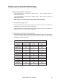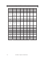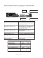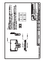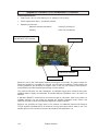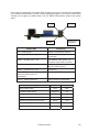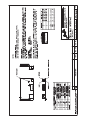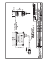
1
INSTRUCTION
MANUAL
MICRO 4000® NET Web Guide Control System
Software Versions:
M4K 23.xx
DLG 21.xx
RMT03 GP21.xx
RMT03 AR21.xx
Document P/N 990040-230 (Rev. 2)
P.O. Box 7816 • Madison, Wisconsin 53707
Ph: 608/223-0625 or 1-888-422-2893 • Fax: 608/223-0074 • E-mail: [email protected]
Table of Contents
MICRO 4000® NET Web Guide Control System ............................................................................. 3
Introduction ................................................................................................................................ 4
Installation.................................................................................................................................. 7
Operation ................................................................................................................................. 10
Troubleshooting ....................................................................................................................... 11
Appendix 1 / Motor Drive Calibration ....................................................................................... 15
MICRO 4000® NET Controller........................................................................................................ 16
Introduction .............................................................................................................................. 17
Parameters .............................................................................................................................. 17
Appendix 1 / Parameter Summary .......................................................................................... 39
Appendix 2 / Error Codes ........................................................................................................ 42
Appendix 3 / Oscillation Function (Optional) ........................................................................... 43
Appendix 4 / Inhibit Input ......................................................................................................... 45
Appendix 5 / Discrete Isolated Inputs ...................................................................................... 46
Appendix 6 / Discrete Isolated Outputs ................................................................................... 48
Appendix 7 / Analog Inputs and Outputs ................................................................................. 50
PointSource™, WideArray™, and Hi-Temp Edge Detectors......................................................... 56
Introduction .............................................................................................................................. 57
Setup ....................................................................................................................................... 58
Calibration................................................................................................................................ 59
Maintenance ............................................................................................................................ 60
AccuBeam® 3 Digital Line Guide Sensor ...................................................................................... 61
Introduction .............................................................................................................................. 62
Installation................................................................................................................................ 63
Operation ................................................................................................................................. 64
Calibration................................................................................................................................ 66
Parameters .............................................................................................................................. 72
Keypad Lock ............................................................................................................................ 79
Troubleshooting ....................................................................................................................... 80
Maintenance ............................................................................................................................ 81
Appendix 1 / Parameter Summary .......................................................................................... 82
Appendix 2 / Line Guide Test Pattern ..................................................................................... 83
AccuWeb® Linear Actuators ........................................................................................................... 84
Introduction .............................................................................................................................. 85
Setup ....................................................................................................................................... 85
1
Maintenance ............................................................................................................................ 86
Remote Station - Guide Point Adjust ............................................................................................. 89
Introduction .............................................................................................................................. 90
Installation................................................................................................................................ 90
Operation ................................................................................................................................. 91
Parameters .............................................................................................................................. 92
Keypad Lock ............................................................................................................................ 96
Troubleshooting ....................................................................................................................... 97
Remote Station - Auxiliary.............................................................................................................. 98
Introduction .............................................................................................................................. 99
Installation................................................................................................................................ 99
Operation ............................................................................................................................... 100
Keypad Lock .......................................................................................................................... 101
Troubleshooting ..................................................................................................................... 102
Fieldbus Interface......................................................................................................................... 103
Introduction ............................................................................................................................ 104
Installation..............................................................................................................................104
Programming Information ...................................................................................................... 105
Troubleshooting ..................................................................................................................... 118
Appendix 1 / DeviceNet Interface .......................................................................................... 119
Appendix 2 / Profibus Interface ............................................................................................. 122
Appendix 3 / ControlNet Interface ......................................................................................... 125
Appendix 4 / Modbus Plus Interface ...................................................................................... 128
Appendix 5 / Ethernet TCP/IP and Modbus/TCP Interface ................................................... 132
Service / Return Authorization ..................................................................................................... 136
Restocking Policy ......................................................................................................................... 137
Warranty Policy ............................................................................................................................ 138
Installation Drawings .................................................................................................................... 139
Important! Make sure the first two digits of the software version numbers shown on the cover of
this manual match the first two digits of the version numbers displayed by your controller, digital
line guide or remote station. If they do not match contact AccuWeb to obtain the correct manual.
AccuBeam®, AccuWeb®, MICRO 1000®, and MICRO 4000® are registered trademarks of
AccuWeb, Inc.
PointSource™ and WideArray™ are trademarks of AccuWeb, Inc.
2
MICRO 4000® NET Web Guide Control System
MICRO 4000® NET Web Guide Control System
3
Introduction
The MICRO 4000 NET Web Guide Control System is a microprocessor-based control system for
medium to large-sized web guides. It is compatible with AccuWeb’s dynamically compensated
ultrasonic and infrared edge detectors, digital line guide, remote stations, and all linear actuators.
A MICRO 4000 NET system can include up to seven main components:
1. Edge Detector or Line Guide Sensor
PointSource and WideArray Compensated Edge Detectors
•
Ultra-compact housing
•
Available with sensing areas ranging from 0.2” to 18.6” wide [5mm to 472mm]
•
Available with gap widths ranging from 1.5” to 4” [38mm to 102mm]
•
Fully compensated for temperature, humidity, dust, and most other process contaminants
•
Immune to passline variation and web flutter
•
Suitable for long cable length applications
•
Intrinsically-safe models available for hazardous environments
•
Ultrasonic models are ideal for transparent or opaque film, paper, and foil web materials
•
Infrared (IR) models are ideal for non-wovens and other porous web materials
Hi-Temp Compensated Ultrasonic Edge Detector
•
Withstands oven temperatures up to 500 deg F [260 deg C]
•
Available with waveguide tube lengths up to 84” [213cm]
•
Fully compensated for temperature, humidity, dust, and most other process contaminants
•
Immune to passline variation and web flutter
•
Suitable for long cable length applications
•
Intrinsically-safe models available for hazardous environments
•
Ideal for transparent or opaque film, paper, and foil web materials
AccuBeam 3 Digital Line Guide Sensor
4
•
Ultra-compact housing
•
Three light source colors and three illumination angles provide optimal lighting
•
Line and edge guiding modes
•
Pattern matching algorithm locks onto hard-to-see lines
•
Auto-calibration automatically selects optimum settings
•
Environmentally-sealed function switches and display
•
Suitable for long cable length applications
MICRO 4000® NET Web Guide Control System
2. MICRO 4000 NET Controller Board
•
Single-board design
•
Auto-recovery after power interruption
•
Non-volatile memory for user-settable parameters and operating modes
•
On-board parameter entry keypad and display
•
Two edge detector inputs for centerline guiding
•
Serial I/O port for remote station and digital line guide
•
Analog ±10 VDC output for controlling motor drive
•
Actuator end-of-travel inputs:
Potentiometer input for electronically-adjustable limits
Limit switch inputs for fixed limits
•
Opto-isolated inhibit input
•
Opto-isolated fault indicator output
•
Auxiliary analog and digital I/O
•
Input voltage: 90-132 VAC or 180-264 VAC, 50/60 Hz, single-phase
3. MICRO 4000 NET PWM Motor Drive
•
Fast, accurate response to web movement
•
Drives brush or brushless DC motors up to 746 watts (1.0 HP)
4. MICRO 4000 NET Enclosure
•
Low profile
•
Environmentally-sealed function switches
•
Cam-locked door with double-bit insert key
•
External mounting feet
5. AccuWeb Linear Actuator
•
Available with brush or brushless DC motors up to 746 watts (1.0 HP).
•
Available with standard stroke lengths up to ± 6” [± 152mm] (other lengths available upon
request)
•
Available with limit switches or potentiometer for sensing end-of-travel limits and servocenter position
MICRO 4000® NET Web Guide Control System
5
6. Fieldbus Interface (optional)
•
Links the MICRO 4000 NET system with a remote PLC or computer through a fieldbus
network
•
Compatible with most fieldbus protocols, including DeviceNet, Profibus, ControlNet,
Modbus Plus, Modbus/TCP, and Ethernet TCP/IP
•
Provides control of operating mode, guide point position, and other functions
•
Permits monitoring of actuator position, web position, and other status indicators
7. Remote Station (optional)
•
Rugged, ultra-compact housing
•
Remote guide point adjustment or remote access to digital line guide’s front panel
•
Environmentally-sealed function switches and display
Product Specifications:
6
•
Enclosure size (H x W x D): 9.84” [250mm] x 11.81” [300mm] x 5.91” [150mm]
•
Power requirements: 90-132 VAC or 180-264 VAC, 50/60 Hz, single-phase
•
Operating environment:
Maximum ambient temperature
120 deg F [48.9 deg C]
Humidity
0-90% non-condensing
MICRO 4000® NET Web Guide Control System
Installation
The MICRO 4000 NET system has been tested, calibrated, and run at the factory in a
closed-loop configuration. After installation, most systems may be started up and operated
without further adjustment. Refer to the connection and wiring diagrams on page 139 for cable
installation information.
OEMs: If shipping clamps and spreaders are removed, make sure that they are re-installed
prior to forwarding to the final destination. Verify that all mechanical and electronic
components are secured for shipment.
1. Linear Actuator and Guide
Install the web guide and linear actuator into the machine. Refer to the guide and actuator
application drawings on page 139 for installation information. Once the web guide is installed,
it must be trammed to the rest of the machine.
Note: Make sure the actuator is in the servo-center position before tramming the web guide.
This may not be possible until after step 5, below.
Important: Special attention must be given to the actuator mounting. Any mechanical
compliance or backlash in the actuator mounting will seriously affect guiding accuracy.
Deflections of a few thousandths of an inch will reduce the performance of the system. Also,
an anti-rotation bracket is required for most applications. The actuator must be allowed to
gimbal slightly on the ball rod ends to accommodate minor actuator mounting misalignment.
Note: Motor contains no temperature-sensing device to protect motor from excessive
temperature due to failure-to-start or overload. Motor should be protected by other means in
accordance with the NEC and local code requirements.
2. Sensor (Edge Detector or Digital Line Guide)
Install the sensor (edge detector or digital line guide). Refer to the guide and sensor
application drawings on page 139 for installation information. Use of the AccuWeb edge
detector mounting bracket simplifies installation and adjustment.
The sensor cable should be long enough so that the sensor may be repositioned if the web
width or web path changes. The standard cable length is 12 feet. Longer cables are available
upon request.
Note: The cables supplied with the system have been chosen for specific shielding and
capacitance properties. DO NOT splice or replace these cables with any other style or
configuration of cable. This can cause serious degradation or complete loss of system
performance. DO NOT SPLICE CABLES. Longer cables are available upon request.
3. Control Enclosure
Install the control enclosure on a rigid mount such as a wall or secure framework. Do not
install the control enclosure on the side of a dryer or in other high temperature areas. Also, do
not install the control enclosure on a moving winder structure.
MICRO 4000® NET Web Guide Control System
7
4. Electrical Power
Note: Electrical power must be provided from a customer-supplied disconnect. Connections
must comply with NEC 590 and other local codes.
a) Verify that the power source is off and locked out.
b) Install the electrical power cord through the right-most cord grip.
c) Connect the cable to the terminal block located inside the enclosure.
d) Make sure the circuit board is free of metallic debris such as screws, lockwashers, and
wire strands.
e) If any of the cables have been removed, shortened, or modified in any way, make sure
the connections agree with the appropriate connection and wiring diagrams located on
page 139.
5. Static Test
a) Apply power to the system.
b) Press the MANUAL button.
c) Press the IN and OUT buttons several times. The actuator and web guide mechanism
should move freely and without hesitation.
d) Press and hold the IN button. When the guide mechanism gets near the In limit, release
the button.
e) Jog the IN button repeatedly until the actuator automatically stops at its end-of-travel
limit.
Caution: If the actuator or web guide mechanism hits a mechanical obstruction before
the actuator stops automatically at its end-of-travel limit, release the button immediately.
Continued activation will cause serious damage to the actuator motor and/or guide
mechanism.
f)
Repeat the previous two steps using the OUT button in order to check the Out limit.
g) Press the SERVO-CENTER button and verify that the actuator drives to the center of its
stroke.
6. Dynamic Test
a) Press the SERVO-CENTER button and verify that the actuator drives to the center of its
stroke. This also places the web guide in its center (or tram) position.
b) Thread the web through the machine and put a slight tension on it so that the web is in its
normal operating position.
8
MICRO 4000® NET Web Guide Control System
Repeat steps c) through h) for each sensor:
c) Press the SERVO-CENTER button.
d) Position the sensor.
Edge detector: Place at the edge of the web. The edge detector’s null indicator LED will
turn off when the edge detector is positioned correctly. The scribed lines on the edge
detector indicate the approximate location of the detector’s guide point.
Note: The default calibration supplied with the system should work for most materials.
However, if the null indicator LED does not turn off, then the detector may need to be
calibrated. Refer to page 59 for calibration instructions.
Digital line guide: Position the sensor so that it is approximately centered over the
registration line or edge. Calibrate the sensor (refer to page 66 for calibration
instructions). When the sensor is calibrated and positioned correctly an indicator dot will
appear in the display under the line or edge you want to track.Press the EDGE A, EDGE
B, or LINE button to select the sensor under test.
e) Press the AUTOMATIC button.
f)
Slowly move the sensor left or right and observe how the guide reacts. The guide should
move the web so that it follows (or chases) the movement of the sensor.
Edge detector: The guide should move the web so that the edge of the web is always
aligned with the edge detector’s guide point.
Digital line guide: The guide should move the web so that the line or edge pattern is
always aligned with the line guide’s sight point.
Note: If the guide does not follow the movement of the sensor and moves in the opposite
direction, then the sensor polarity (parameters 3, 4, or 50) is not correct and must be
changed. Refer to page 17 for more information about setting controller parameters.
g) If the guide mechanism oscillates around the guide point or overshoots excessively when
steering in response to an abrupt change in web position, the servo gain (parameter 5) is
too high and must be lowered. Refer to page 17 for more information about setting
controller parameters.
MICRO 4000® NET Web Guide Control System
9
Operation
The MICRO 4000 NET may be configured for a wide variety of applications, but most
configurations share the same basic operating procedure:
1) Press the SERVO-CENTER button and wait for the web guide to drive to the center of travel.
2) Thread the web through the machine.
3) Position the sensors.
One edge detector: Place the detector near the edge of the web. Move the detector towards
the web until its null indicator LED turns off. Note: The scribed lines on the edge detector
indicate the approximate location of the detector’s guide point.
Two edge detectors (centerline guiding): Press the EDGE A button. Place detector A near
the edge of the web. Move detector A towards the web until its null indicator LED turns off.
Press the EDGE B button. Place detector B near the opposite edge of the web. Move
detector B towards the web until its null indicator LED turns off. Note: The scribed lines on
the edge detector indicate the approximate location of the detector’s guide point.
Digital line guide: Position the sensor so that it is approximately centered over the
registration line or edge. When it is positioned correctly an indicator dot will appear in the
display under the line or edge you want to track. Refer to page 61 for more information about
operating the line guide.
4) Press the EDGE A, EDGE B, or LINE button. For Centerline mode (centerline guiding), press
the EDGE A and EDGE B buttons simultaneously.
5) Press the AUTOMATIC button. The system will now guide the web.
Scribe mark
Scribe marks
Null indicator
Null indicator
Move detector until
null indicator turns off
Web
PointSource detector
Web
WideArray detector
Centerline guiding with WideArray detectors
10
MICRO 4000® NET Web Guide Control System
Troubleshooting
The following checklist has been provided to assist in the analysis and repair of potential trouble
situations with the MICRO 4000 NET system. If a situation occurs that is not described in this list,
contact AccuWeb for assistance.
Problem
Solution
The system will not work in Automatic, Manual, or ServoCenter mode.
Check items 1, 2, 3, 4, and 5
in the table below.
When the system is in Automatic mode, the web guide steers
the web in the wrong direction.
Check item 6 in the table
below.
The system oscillates in Automatic mode even though web is
not being pulled through the machine.
Check items 7 and 8 in the
table below.
The system is unstable in Automatic mode while pulling web.
Check items 9, 10, 11, and 12
in the table below.
The actuator extends or retracts beyond the actuator’s end-oftravel limits then jams.
Check items 13, 14, 15, 16,
17, 18, and 19 in the table
below.
The web guide or actuator hits a mechanical stop before
reaching the actuator's end-of-travel limit.
Check item 15 in the table
below.
The system will not work in Automatic mode but works
correctly in Manual and Servo-Center mode.
Check items 20, 21, and 22 in
the table below.
While in Automatic mode the web guide or actuator moves too
fast or slow in response to large changes in the position of the
edge of the web (such as a splice).
Check item 23 in the table
below.
While in Manual mode the web guide or actuator moves too
fast or too slow.
Check item 24 in the table
below.
The numeric display is showing a flashing ‘99’ error code.
If error code is ‘10’, then
check item 5 in the table
below, else refer to page 42
for more information about
error codes.
Item
Description / Repair Procedure
1
AC power. If the LED data displays are not lit, check the AC power and
repair if not connected.
2
No output from the PWM motor drive. Connect a digital voltmeter to the
actuator motor leads at J5 terminals 1 and 2. Press the MANUAL button
and then press and hold the IN or OUT button. If there is no voltage but the
LED data displays are lit, the PWM motor output has failed and the system
must be returned for repair.
3
Actuator failure. If there is motor voltage present in the previous step but
the actuator does not move, the actuator motor or cable has failed.
Troubleshoot and repair as required, or return the equipment for repair.
MICRO 4000® NET Web Guide Control System
11
4
INHIBIT input polarity is set wrong. Set parameter 19 to the correct
value. Refer to page 17 for more information about setting controller
parameters.
5
New software was installed during routine maintenance.
or
Non-volatile memory contains invalid data or has malfunctioned.
Reset all parameters to their default values:
Caution: This procedure will erase all previously entered parameter
settings! Be sure to record all current settings on page 39 before
performing this step. If you are installing new software, then you must
record the current settings before installing the new microcontroller
chip.
1. Turn the AC power off.
2. Press and hold the EXIT button.
3. Turn the AC power on.
4. When the ‘reset’ message appears on the numeric display, release the
EXIT button.
5. Set parameter 2 (end-of-travel mode) and other parameters to their
previous values. Refer to page 17 for more information about setting
controller parameters.
6
Sensor polarity is wrong. The value of parameter 3, 4, or 50 must be
changed for the selected sensor. Refer to page 17 for more information
about setting controller parameters.
7
Servo gain is too high. Decrease the value of parameter 5. Refer to page
17 for more information about setting controller parameters.
8
End play in the actuator or mounting. Press the MANUAL button and
then press IN and OUT buttons several times. Actuator operation should be
smooth and free, without binding. Firmly grasp the web guide mechanism
moving part and push and pull to check for end play. Observe the actuator,
mechanical components, and mounting hardware. There should be no
observable motion in the mechanical system. If motion is noted, repair the
web guide or actuator as required, or return the equipment for repair.
9
Sensor in wrong position.
Unwind stand: The sensor should be located down-web, close to the last
shifting idler roll. Refer to the guide application drawings on page 139.
Winder stand: The sensor should be located up-web before the last fixed
idler roll, one to two web widths from the shifting base. Refer to the guide
application drawings on page 139.
Intermediate guides: The sensor should be placed close to the exiting
idler roll. Refer to the guide application drawings on page 139.
12
10
Excessive chuck wobble. Decrease the web speed or re-chuck the roll of
material.
11
Web tension is low or tension control varies. Increase the web tension
or repair the tension control.
MICRO 4000® NET Web Guide Control System
12
Excessive web curl. If web flutter or curl exists, change parameters 6 and
18 to higher values. Refer to page 17 for more information about setting
controller parameters.
13
All actuators. End-of-travel mode is incorrect. Set parameter 2 to the
correct value. Refer to page 17 for more information about setting controller
parameters.
14
All actuators. Actuator cable wires are broken, shorted or connected
to wrong terminals of J5. Refer to the connection diagrams on page 139.
Check wiring at J5 and check the actuator cable for broken or shorted
wires.
15
Actuators with potentiometer feedback (MT, SF, HL, HF, HT, and UHT).
End-of-travel limits not set correctly. Parameters 9 and 10 must be
adjusted to stop the actuator before the web guide or actuator hits any
obstruction. Refer to page 17 for more information about setting controller
parameters.
16
Actuators with potentiometer feedback (MT, SF, HL, HF, HT, and UHT).
Potentiometer failure. Refer to the potentiometer replacement procedure
on page 87.
17
Actuators with limit switches (MM, MME, MN, and MNE). Limit switch
failure. Check the limit switch voltage at J5 terminals 5 and 6 (terminal 10
is GND). This voltage should normally be 0.0 VDC (switch is closed), then
jump to +5.0 VDC when the limit is reached (switch opens). If the correct
voltages are not present, replace the limit switch in the actuator or return
the actuator for repair.
18
Actuators with limit switches (MX). Limit switch failure. The end-oftravel limit switches in the MX-series actuators directly control the motor
circuit and cannot be monitored externally. If a limit switch has failed,
replace the switch or return the actuator for repair.
19
Reversed motor wires. Restore the motor wire connections at J5
terminals 1 and 2 to the proper connection. Refer to the connection
diagrams on page 139. Change the value of parameters 3, 4, or 50 as
required. Refer to page 17 for more information about setting controller
parameters.
20
Edge detector not calibrated. Refer to page 59 for calibration instructions.
21
Edge detector: transducers covered with dust or other material. Clean
the edge detector transducer face with a cloth dampened with water or a
mild detergent solution. If the contamination cannot be removed with this
method, return the edge detector for repair.
Digital line guide: optics covered with dust or other material. Clean the
underside of the sensor with a soft cloth dampened with water or a cleaning
solution suitable for photographic lenses. If the contamination cannot be
removed with this method, return the sensor for repair.
22
Edge detector failure. Observe the value of parameter 14 or 15 as
required. If this value is below 100, the edge detector is failing and must be
returned for repair. Refer to page 17 for more information about displaying
controller parameter settings.
23
Auto-mode speed limit setting is incorrect. Change the value of
parameter 7. Refer to page 17 for more information about setting controller
parameters.
MICRO 4000® NET Web Guide Control System
13
24
14
Manual-mode speed setting is incorrect. Change the value of parameter
8. Refer to page 17 for more information about setting controller
parameters.
MICRO 4000® NET Web Guide Control System
Appendix 1 / Motor Drive Calibration
Note: The PWM motor drive module is not easily accessible, however user adjustment is typically
not necessary and is not recommended.
PWM Motor Drive
The PWM motor drive converts the system command voltage into a drive voltage for the actuator
motor. The motor drive consists of a separate power supply and PWM servo amplifier. This servo
amplifier is run in voltage mode for highest response and accuracy. All adjustments are sealed
when the system is shipped and should not require adjustment. If adjustment is required, this is
easily accomplished using the following procedure:
Note: A digital voltmeter (DVM) with at least 2½ digit accuracy will be required during the
following procedure.
Adjustment Procedure:
1) Verify that the servo module is configured for voltage mode with the DIP switch set as
follows:
Switch
Setting
1
ON
2
OFF
3
OFF
4
OFF
2) Put the system into Manual mode and drive the actuator to ensure that it is not at a limit.
3) Connect the DVM leads to terminals 13 and 14 (motor output).
4) Verify that the DVM reads between +1.00 and -1.00 volts. Adjust R4 (test--offset) on the
servo amplifier module if required.
5) Put the system into Automatic mode and verify that the system responds quickly to
position errors without oscillation.
6) If a whistling noise is heard from the servo amplifier module, adjust R3 (reference input
gain) CCW until it stops.
7) The other potentiometers are adjusted at the factory and do not require further
adjustment in the field. Do not attempt to adjust these potentiometers.
R1
R2
R3
R4
4 3 2
DIP SW.
1
1
P1
PWM Servo Amplifier
MICRO 4000® NET Web Guide Control System
1 2 3 4 5
P2
15
MICRO 4000® NET Controller
16
MICRO 4000® NET Controller
Introduction
The MICRO 4000 NET controller’s main functions include polling the web sensors, end-of-travel
sensors, and control inputs, processing the input data, and sending the results to the servoamplifier and status outputs.
The controller’s main features include the following:
•
Compatible with all ultrasonic and infrared PointSource and WideArray edge detectors,
ultrasonic Hi-Temp edge detectors, and AccuBeam 3 digital line guide. These sensors are
described on pages 56 and 61.
•
Has a built-in parameter-entry keypad and display.
•
Has a variety of digital inputs and outputs that allow the customer’s PLC to control its
operating modes and monitor its status. These are described on pages 45, 46, and 48. In
addition, the controller can be connected to a wide variety of fieldbus networks by installing
an optional Fieldbus Interface card. This card is described on page 103.
•
Has several analog inputs and outputs that may be used for interfacing to voltage-output
sensors, PLCs and other MICRO 4000 NET controllers. A setup procedure for these ports is
described on page 50.
•
Compatible with the Remote Stations described on pages 89 and 98.
Parameters
The MICRO 4000 NET system is configured by setting programmable parameters. These
parameters are stored in non-volatile memory and may be examined or changed by using the
parameter-entry keypad and display located on the MICRO 4000 NET board.
Note that the CODE and DATA display will show dashes immediately after power is turned on
and after the EXIT button is pressed. The dashes indicate that no parameter is currently selected
for examination or adjustment, but that the system is operating normally.
- -
- - - - -
CODE
DATA
The general procedure for reading and/or changing the parameters is as follows:
1) Press the UP (▲) or DOWN (▼) CODE buttons to select the parameter you want to examine
and/or adjust. Each parameter has a unique code number.
2) Press the UP (▲) or DOWN (▼) DATA buttons to adjust the parameter’s setting.
3) Press ENTER to store the new data value in non-volatile memory. To leave the data value at
its original value press EXIT, or press the UP (▲) or DOWN (▼) CODE buttons.
The parameters are described below:
Software Version
1
x x. x x
This parameter displays the software version.
MICRO 4000® NET Controller
17
End-of-Travel Mode
2
0
No feedback. This mode is used when the system has no motor drive
output.
2
1
Actuators with potentiometer feedback (MT, SF, HL, HF, HT, and UHT).
These actuators use a potentiometer to sense actuator position and have
adjustable end-of-travel and servo-center limits.
Caution: To prevent jamming of the actuator make sure the end-of-travel
limits are set correctly. Refer to page 85 for more information about
setting end-of-travel limits.
2
2
Actuators with limit switches (MM, MME, MN, and MNE). These
actuators use fixed limit switches to sense actuator position. Their endof-travel limits are factory set.
2
3
Actuators with limit switches (MX). These actuators use fixed limit
switches to sense actuator position. Their end-of-travel limits are factory
set.
Note: The default setting for this parameter is 4. After resetting all parameters to their default
values (refer to page 11, troubleshooting item 5) you must set this parameter to 0, 1, 2, or 3
before setting other parameters and/or operating the system.
Input A Polarity
3
0
The actuator will move Out when edge detector A is unblocked, or the
digital line guide’s sight point is to the left of the line or edge it is
following. This is the default setting.
3
1
The actuator will move Out when edge detector A is blocked, or the
digital line guide’s sight point is to the right of the line or edge it is
following.
Input B Polarity
4
0
The actuator will move Out when edge detector B is unblocked, or the
digital line guide’s sight point is to the left of the line or edge it is
following.
4
1
The actuator will move Out when edge detector B is blocked, or the
digital line guide’s sight point is to the right of the line or edge it is
following. This is the default setting.
4 0
This parameter determines the response time and accuracy of the
system. In Automatic mode, the system produces a motor drive voltage
proportional to web position error. Higher gain will increase the drive
voltage at a given position error. For best response time and accuracy,
set the servo gain to the highest value that does not produce excessive
overshoot or oscillation. The default value is 40.
Servo Gain
5
Range: 0 to 255
18
MICRO 4000® NET Controller
Maximum Deadband
6
1 0
Range: 0 to 100
The maximum deadband is a zone around the sensor guide point where
the motor drive is turned off. The higher the Maximum Deadband value is
set, the farther the web edge or line must move away from the guide
point before the motor drive is turned on. This parameter is typically used
to compensate for edge curl and web flutter. The Maximum Deadband
value must be higher than the Minimum Deadband value. The default
value is 10.
Auto-Mode Speed Limit
7
8 0
Range: 0 to 120
This parameter limits the top speed of the actuator in Automatic mode.
The higher this value is set, the faster the actuator can move. The
default value is 80.
Manual-Mode Speed
8
8 0
Range: 0 to 120
This parameter determines how fast the actuator will move in Manual
and Servo-Center mode. The higher this value is set, the faster the
actuator will move. The default value is 80.
In End-of-Travel Limit
9
6 7
Range: 0 to 255
This parameter works only with actuators that have potentiometer
feedback (MT, SF, HL, HF, HT, and UHT). It sets the maximum distance
that the actuator can move In. To increase this distance, set this
parameter to a lower value. The default value is 67.
Important: Refer to page 85 for minimum and maximum values.
Note: Use parameter 26 to examine the current actuator position value.
Out End-of-Travel Limit
1 0
1 8 9
Range: 0 to 255
This parameter works only with actuators that have potentiometer
feedback (MT, SF, HL, HF, HT, and UHT). It sets the maximum distance
that the actuator can move Out. To increase this distance, set this
parameter to a higher value. The default value is 189.
Important: Refer to page 85 for minimum and maximum values.
Note: Use parameter 26 to examine the current actuator position value.
Servo-Center Position
1 1
1 2 8
Range: 0 to 255
This parameter works only with actuators that have potentiometer
feedback (MT, SF, HL, HF, HT, and UHT). It sets the home position for
the actuator when Servo-Center mode is selected. To move the servocenter position closer to the In limit, set this parameter to a lower value.
To move the servo-center position closer to the Out limit, set this
parameter to a higher value. The default value is 128.
Important: Refer to page 85 for minimum and maximum values.
Note: Use parameter 26 to examine the current actuator position value.
MICRO 4000® NET Controller
19
Input A Type
1 2
0
Sensor A is not installed.
1 2
1
Sensor A is an ultrasonic or IR edge detector connected to the Edge
Detector A input. This is the default setting.
Note: Set parameter 55 to select sensor type.
1 2
2
Sensor A is a digital line guide connected to the Serial I/O interface.
1 2
3
Sensor A is an external analog device connected to Analog Input 1.
Note: In order to select Input A through the front-panel switchpad, fieldbus or Discrete Isolated
Inputs, parameter 12 must be set to 1 or higher.
Input B Type
1 3
0
Sensor B is not installed. This is the default setting.
1 3
1
Sensor B is an ultrasonic or IR edge detector connected to the Edge
Detector B input.
Note: Set parameter 56 to select sensor type.
1 3
2
Sensor B is a digital line guide connected to the Serial I/O interface.
1 3
3
Sensor B is an external analog device and is connected to Analog Input
2.
Note: If parameter 2 is set to 1, then Analog Input 2 must be connected
to the actuator’s position-sensing potentiometer.
Note 1: In order to select Input B through the front-panel switchpad, fieldbus or Discrete Isolated
Inputs, parameter 13 must be set to 1 or higher.
Note 2: In order to select Centerline mode through the front-panel switchpad, fieldbus or Discrete
Isolated Inputs, parameters 12 and 13 must both be set to 1 or higher.
Edge Detector A Signal Level
1 4 a a. b b b
This parameter displays edge detector A’s signal levels. Digits aa display
the beam number and digits bbb display the signal level. Use the DATA
buttons to select the desired beam.
Edge Detector B Signal Level
1 5 a a. b b b
20
This parameter displays edge detector A’s signal levels. Digits aa display
the beam number and digits bbb display the signal level. Use the DATA
buttons to select the desired beam.
MICRO 4000® NET Controller
Edge Detector A Transmit Level
1 6 a a. b b b
This parameter displays edge detector A’s transmit levels. Digits aa
display the beam number and digits bbb display the transmit level. Use
the DATA buttons to select the desired beam.
Edge Detector B Transmit Level
1 7 a a. b b b
This parameter displays edge detector B’s transmit levels. Digits aa
display the beam number and digits bbb display the transmit level. Use
the DATA buttons to select the desired beam.
Minimum Deadband
1 8
5
Range: 0 to 100
The minimum deadband is a zone around the sensor guide point that the
web edge or line must enter before the motor drive is turned off. Once
the web edge or line position enters this zone, it must then move outside
of the maximum deadband zone before the motor drive is turned on. The
Minimum Deadband value must be lower than the Maximum Deadband
value. The default value is 5.
INHIBIT Input Mode
Refer to page 45 for more information about the INHIBIT input.
1 9
0
The actuator will run only if the INHIBIT input is activated. The INHIBIT
input controls the actuator in Automatic, Manual, or Servo-Center mode.
1 9
1
Same function as option 0, except the polarity of the INHIBIT input is
inverted. This is the default setting.
1 9
2
The actuator will run only if the INHIBIT input is activated. The INHIBIT
input controls the actuator only in Automatic mode.
1 9
3
Same function as option 2, except the polarity of the INHIBIT input is
inverted.
Note: If your application requires an opto-isolated INHIBIT input, then set parameter 72 to 1.
Calibrate Edge Detector A
2 0
0
Range: 0 to 2
This parameter initiates the calibration of edge detector A. Refer to page
59 for calibration instructions.
Calibrate Edge Detector B
2 1
Range: 0 to 2
0
This parameter initiates the calibration of edge detector B. Refer to page
59 for calibration instructions.
MICRO 4000® NET Controller
21
Edge Detector A Blocked Level
2 2
0
Range: 0 to 255
This parameter determines the blocked signal level for edge detector A
and is automatically set by the edge detector calibration procedure. The
default value is 0.
This parameter value should not be changed manually.
Edge Detector B Blocked Level
2 3
0
Range: 0 to 255
This parameter determines the blocked signal level for edge detector B
and is automatically set by the edge detector calibration procedure. The
default value is 0.
This parameter value should not be changed manually.
Sensor A Length
2 4
2
Range: 2 to 128
This parameter configures the system for the number of sensing beams
in sensor A. The default value is 2.
Refer to the table of sensor models on page 58.
Note: To reduce the sensing area of a WideArray detector, change parameter 76.
Sensor B Length
2 5
2
Range: 2 to 128
This parameter configures the system for the number of sensing beams
in sensor B. The default value is 2.
Refer to the table of sensor models on page 58.
Note: To reduce the sensing area of a WideArray detector, change parameter 77.
Actuator Position Display
This parameter displays the position of the actuator. The display format depends on the type of
actuator installed:
2 6
0
Range: 0 to 255
2 6
a b c
Actuators with potentiometer feedback (MT, SF, HL, HF, HT, and UHT).
The data display indicates the position of the actuator’s end-of-travel
potentiometer.
Actuators with limit switches (MM, MME, MN, and MNE). The data
display indicates the state of the actuator’s limit switches:
a = IN limit switch (0 = activated, 1 = deactivated)
b = POLARITY switch (0 = activated, 1 = deactivated)
c = OUT limit switch (0 = activated, 1 = deactivated)
2 6
a b c
Actuators with limit switches (MX). The data display indicates the state of
the actuator’s limit switches:
a = don’t care
b = don’t care
c = OUT POLARITY switch (0 = activated, 1 = deactivated)
22
MICRO 4000® NET Controller
Power-Up Mode
2 7
0
The system will power-up in the same operating mode that was selected
when last powered-down. All inputs are momentary. This is the default
setting.
2 7
1
The system will power-up in Manual mode. All inputs are momentary.
2 7
2
The system will power-up in Servo-Center mode. All inputs are
momentary.
2 7
3
The system will power-up in Automatic mode. All inputs are momentary.
2 7
4
The system will power-up in Manual mode. All inputs are maintained.
2 7
5
The system will power-up in Manual mode and Edge A (Input A) will be
selected. All inputs are momentary.
2 7
6
The system will power-up in Manual mode and Edge B (Input B) will be
selected. All inputs are momentary.
2 7
7
The system will power-up in Manual mode and Line (Input C) will be
selected. All inputs are momentary.
2 7
8
The system will power-up in Manual mode and Edge A and Edge B will
be selected (Centerline mode). All inputs are momentary.
Note: This parameter also affects the operation of the Discrete Isolated Inputs (page 46).
Parameter 28 is reserved for future use.
System ID
2 9 x x x x x
This parameter displays the system ID number.
Password
3 0
0
Range: 0 to 255
This parameter is used for enabling optional software features. To
purchase and install optional features, contact AccuWeb for assistance.
Note: To see which features are enabled, set parameter 29 to 1. The displayed data value
indicates which feature is enabled: 0 = none, 1 = oscillation, 2 = web width monitor, 4 = integrator.
Refer to page 43 for a description of parameters 31, 32, 33, and 34.
MICRO 4000® NET Controller
23
LED Indicator Mode
3 5
0
The front-panel switchpad LEDs and edge detector null indicator LEDs
are enabled.
In this mode one or both null LEDs may be operational depending on
which edge detector is selected by the switchpad, fieldbus, or Discrete
Isolated Inputs.
If Edge A is selected, then edge detector A’s null LED indicates the
position of web edge A and detector B’s null LED is off.
If Edge B is selected, then edge detector B’s null LED indicates the
position of web edge B and detector A’s null LED is off.
If Edge A and Edge B are both selected (Centerline mode), then edge
A’s null LED and edge B’s null LED operate in tandem and indicate the
position of the web’s centerline.
This is the default setting.
3 5
1
The switchpad LEDs and edge detector null indicator LEDs are enabled.
In this mode each edge detector null LED indicates the position of the
web sensed by that detector alone, and both null LEDs are always
operational.
3 5
2
The switchpad LEDs are enabled and the edge detector null indicator
LEDs are always off. Use this setting if the web is photosensitive.
3 5
3
The switchpad LEDs and edge detector null indicator LEDs are always
off. Use this setting if the web is photosensitive.
3 6
0
Sensor A has a 1.5 inch gap.
3 6
1
Sensor A has a 4.0 inch gap. This is the default setting.
3 6
2
Sensor A has an 8.0 inch gap.
3 7
0
Sensor B has a 1.5 inch gap.
3 7
1
Sensor B has a 4.0 inch gap. This is the default setting.
3 7
2
Sensor B has an 8.0 inch gap.
Sensor A Gap
Sensor B Gap
24
MICRO 4000® NET Controller
Analog Output 1
3 8
0
The output voltage is 0.0 volts. This is the default setting.
3 8
1
The output voltage is proportional to the motor drive command signal.
The output voltage range is –10 to +10 volts.
3 8
2
The output voltage is proportional to the signal read by Input A, Input B,
Input C or the centerline combination of Inputs A and B. The inputs are
selected by the front-panel switchpad, fieldbus, or Discrete Isolated
Inputs. The output voltage range is –10 to +10 volts.
3 8
3
Same function as option 2, except the output voltage range is 0 to +10
volts.
3 8
4
The output voltage is proportional to the signal read by Input A. The
output voltage range is –10 to +10 volts.
3 8
5
Same function as option 4, except the output voltage range is 0 to +10
volts.
3 8
6
The output voltage is proportional to the signal read by Input B. The
output voltage range is –10 to +10 volts.
3 8
7
Same function as option 6, except the output voltage range is 0 to +10
volts.
3 8
8
The output voltage is proportional to the web width. The remote station
sets the output voltage range.
3 8
9
The output voltage is proportional to the voltage at Analog Input 1. The
output voltage range is -10 to +10 volts.
3 8
1 0
Same function as option 9, except the output voltage range is 0 to +10
volts.
3 8
1 1
The output voltage is proportional to the voltage at Analog Input 2. The
output voltage range is -10 to +10 volts.
3 8
1 2
Same function as option 11, except the output voltage range is 0 to +10
volts.
3 8
1 3
The output voltage is proportional to the guide point value. The output
voltage range is -10 to +10 volts.
3 8
1 4
Same function as option 13, except the output voltage range is 0 to +10
volts.
3 8
1 5
This option is used in resolving-centerline systems only. The output
voltage drives the resolver’s controller. The output voltage range is -10 to
+10 volts.
3 8
1 6
Same function as option 15, except the output voltage range is 0 to +10
volts.
[continued on next page]
MICRO 4000® NET Controller
25
3 8
1 7
This option is used for controlling a servo-valve. The output voltage
reacts to positive web error only. The output voltage range is 0 to +10
volts.
3 8
1 8
This option is used for controlling a servo-valve. The output voltage
reacts to negative web error only. The output voltage range is 0 to +10
volts.
Note: For option 1 the output voltage range and scale depend on several parameters, including
Input Polarity, Servo Gain, Minimum Deadband, Maximum Deadband, and Auto-Mode Speed
Limit. Options 2 through 7 automatically scale the full sensing range of the sensor to the full range
of the analog output, and options 2 and 3 are also affected by Input Polarity.
Analog Output 2 (servo-amplifier command signal)
3 9
0
The output voltage is 0.0 volts.
3 9
1
The output voltage is proportional to the motor drive command signal.
The output voltage range is –10 to +10 volts. This is the default setting.
3 9
2
The output voltage is proportional to the signal read by Input A, Input B,
Input C or the centerline combination of Inputs A and B. The inputs are
selected by the front-panel switchpad, fieldbus, or Discrete Isolated
Inputs. The output voltage range is –10 to +10 volts.
3 9
3
Same function as option 2, except the output voltage range is 0 to +10
volts.
3 9
4
The output voltage is proportional to the signal read by Input A. The
output voltage range is –10 to +10 volts.
3 9
5
Same function as option 4, except the output voltage range is 0 to +10
volts.
3 9
6
The output voltage is proportional to the signal read by Input B. The
output voltage range is –10 to +10 volts.
3 9
7
Same function as option 6, except the output voltage range is 0 to +10
volts.
3 9
8
The output voltage is proportional to the web width. The remote station
sets the output voltage range.
3 9
9
The output voltage is proportional to the voltage at Analog Input 1. The
output voltage range is -10 to +10 volts.
3 9
1 0
Same function as option 9, except the output voltage range is 0 to +10
volts.
3 9
1 1
The output voltage is proportional to the voltage at Analog Input 2. The
output voltage range is -10 to +10 volts.
[continued on next page]
26
MICRO 4000® NET Controller
3 9
1 2
Same function as option 11, except the output voltage range is 0 to +10
volts.
3 9
1 3
The output voltage is proportional to the guide point value. The output
voltage range is -10 to +10 volts.
3 9
1 4
Same function as option 13, except the output voltage range is 0 to +10
volts.
3 9
1 5
This option is used in resolving-centerline systems only. The output
voltage drives the resolver’s controller. The output voltage range is -10 to
+10 volts.
3 9
1 6
Same function as option 15, except the output voltage range is 0 to +10
volts.
3 9
1 7
This option is used for controlling a servo-valve. The output voltage
reacts to positive web error only. The output voltage range is 0 to +10
volts.
3 9
1 8
This option is used for controlling a servo-valve. The output voltage
reacts to negative web error only. The output voltage range is 0 to +10
volts.
Note: For option 1 the output voltage range and scale depend on several parameters, including
Input Polarity, Servo Gain, Minimum Deadband, Maximum Deadband, and Auto-Mode Speed
Limit. Options 2 through 7 automatically scale the full sensing range of the sensor to the full range
of the analog output, and options 2 and 3 are also affected by Input Polarity.
Analog Offset
4 0
0
The analog offset is off. This is the default setting.
4 0
1
The analog offset source is Analog Input 1. The analog offset polarity is
not inverted.
4 0
2
The analog offset source is Analog Input 1. The analog offset polarity is
inverted.
4 0
3
The analog offset source is Analog Input 2. The analog offset polarity is
not inverted.
4 0
4
The analog offset source is Analog Input 2. The analog offset polarity is
inverted.
Analog Input 1 Range
4 1
0
Analog input 1 is off. This is the default setting.
[continued on next page]
MICRO 4000® NET Controller
27
4 1
1
The range of Analog Input 1 is 0 to +5 volts.
4 1
2
The range of Analog Input 1 is 0 to +10 volts.
4 1
3
The range of Analog Input 1 is -10 to +10 volts.
Analog Input 2 Range (actuator position signal)
4 2
0
If parameter 2 is set to 1, then the range of Analog Input 2 is
automatically set to 0 to +5 volts. If parameter 2 is not set to 1, then
Analog Input 2 is off. This is the default setting.
4 2
1
The range of Analog Input 2 is 0 to +5 volts.
4 2
2
The range of Analog Input 2 is 0 to +10 volts.
4 2
3
The range of Analog Input 2 is -10 to +10 volts.
Analog Input 1 Scale Factor (coarse)
4 3 a a a bb
Range: 0 to 25599
This parameter sets the scale factor for Analog Input 1. Use this
parameter to adjust digits aaa. Use parameter 44 to adjust digits bb.
The default value is 100.
Analog Input 1 Scale Factor (fine)
4 4 a a a bb
Range: 0 to 25599
This parameter sets the scale factor for Analog Input 1. Use this
parameter to adjust digits bb. Use parameter 43 to adjust digits aaa.
The default value is 100.
Analog Input 2 Scale Factor (coarse)
4 5 a a a bb
Range: 0 to 25599
This parameter sets the scale factor for Analog Input 2. Use this
parameter to adjust digits aaa. Use parameter 46 to adjust digits bb.
The default value is 100.
Analog Input 2 Scale Factor (fine)
4 6 a a a bb
Range: 0 to 25599
28
This parameter sets the scale factor for Analog Input 2. Use this
parameter to adjust digits bb. Use parameter 45 to adjust digits aaa.
The default value is 100.
MICRO 4000® NET Controller
Edge-Loss and Line-Loss Detection
4 7
0
Edge-loss and line-loss detection are disabled. This is the default
setting.
4 7
1
Edge-loss and line-loss detection are enabled.
The actuator will stop and the NO FAULT output will turn off when any
active sensor enters the edge-loss or line-loss state. The edge-loss or
line-loss state occurs when an edge detector becomes completely
blocked or unblocked, or the digital line guide loses the line or edge it is
following.
Guiding will resume and the NO FAULT output will turn on when all
sensors have left the edge-loss or line-loss state.
4 7
2
Line-loss detection is enabled.
When the line guide loses the line, edge detector A will record the
position of the web, the system will switch from Line mode to Edge A
mode, and edge detector A will then maintain the web at the recorded
position. When the line guide reacquires the line, the system will switch
back to Line mode.
4 7
3
Line-loss detection is enabled.
When the line guide loses the line, edge detector B will record the
position of the web, the system will switch from Line mode to Edge B
mode, and edge detector B will then maintain the web at the recorded
position. When the line guide reacquires the line, the system will switch
back to Line mode.
4 7
4
Line-loss detection is enabled.
When the line guide loses the line, edge detectors A and B will record
the position of the web, the system will switch from Line mode to
Centerline mode, and edge detectors A and B will then maintain the web
at the recorded position. When the line guide reacquires the line, the
system will switch back to Line mode.
4 7
5
Line-loss detection is enabled.
When the line guide loses the line, the system will switch from Line mode
to Edge A mode, and edge detector A will then maintain the web at the
position specified by Offset 2. When the line guide reacquires the line,
the system will switch back to Line mode.
4 7
6
Line-loss detection is enabled.
When the line guide loses the line, the system will switch from Line mode
to Edge B mode, and edge detector B will then maintain the web at the
position specified by Offset 2. When the line guide reacquires the line,
the system will switch back to Line mode.
4 7
7
Line-loss detection is enabled.
When the line guide loses the line, the system will switch from Line mode
to Centerline mode, and edge detectors A and B will then maintain the
web at the position specified by Offset 2. When the line guide reacquires
the line, the system will switch back to Line mode.
MICRO 4000® NET Controller
29
Servo Gain and Speed Limit Source
4 8
0
Servo Gain is controlled by parameter 5.
Auto-Mode Speed Limit is controlled by parameter 7.
This is the default setting.
4 8
1
Servo Gain and Auto-Mode Speed Limit are controlled by the optional
Fieldbus Interface (page 103).
4 8
2
Servo Gain is controlled by Analog Input 1.
Auto-Mode Speed Limit is controlled by parameter 7.
4 8
3
Servo Gain is controlled by parameter 5.
Auto-Mode Speed Limit is controlled by Analog Input 1.
Input C Type
4 9
0
Sensor C is not installed. This is the default setting.
4 9
1
Sensor C is an ultrasonic or IR edge detector connected to the Edge
Detector A input.
Note: Set parameter 55 to select sensor type.
4 9
2
Sensor C is a digital line guide connected to the Serial I/O interface.
4 9
3
Sensor C is an external analog device connected to Analog Input 1.
Note: In order to select Input C through the front-panel switchpad, fieldbus, or Discrete Isolated
Inputs, parameter 49 must be set to 1 or higher.
Input C Polarity
5 0
0
The actuator will move Out when edge detector A is unblocked, or the
digital line guide’s sight point is to the left of the line or edge it is
following. This is the default setting.
5 0
1
The actuator will move Out when edge detector A is blocked, or the
digital line guide’s sight point is to the right of the line or edge it is
following.
30
MICRO 4000® NET Controller
Switchpad Type
5 1
0
Select this option if the input selection buttons on the front-panel
switchpad are labeled EDGE A, CENTERLINE, and EDGE B.
The EDGE A button selects Input A.
The EDGE B button selects Input B.
The CENTERLINE button selects Inputs A and B.
This switchpad does not allow the selection of Input C.
5 1
1
Select this option if the input selection buttons on the front-panel
switchpad are labeled EDGE A, EDGE B, and LINE.
The EDGE A button selects Input A.
The EDGE B button selects Input B.
The LINE button selects Input C.
To select Centerline mode, press the EDGE A and EDGE B buttons
simultaneously.
5 1
2
Front-panel switchpad operation is the same as option 1.
Bit 7 of the fieldbus Operating Mode Command word selects Automatic
mode. Refer to page 103 for more information about the Fieldbus
Interface. This is the default setting.
Note: This parameter also affects the operation of the Discrete Isolated Inputs (page 46).
AUXILIARY Input Function
Refer to page 46 for more information about the AUXILIARY input.
5 2
0
The AUXILIARY input is off. This is the default setting.
5 2
1
The AUXILIARY input determines which offset is active. To select Offset
2, activate the AUXILIARY input. To select Offset 1, deactivate the
AUXILIARY input.
5 2
2
Same function as option 1, except the polarity of the AUXILIARY input is
inverted.
5 2
3
Activating the AUXILIARY input will enable Oscillation, and deactivating
it will disable Oscillation. Oscillation parameter 31 must be set to 1 or
higher.
Refer to page 43 for more information about the oscillation function.
5 2
4
Same function as option 3, except the polarity of the AUXILIARY input is
inverted.
5 2
5
Activating the AUXILIARY input will switch the system to Automatic
mode.
5 2
6
Same function as option 5, except the polarity of the AUXILIARY input is
inverted.
[continued on next page]
MICRO 4000® NET Controller
31
5 2
7
Activating the AUXILIARY input will set Offset 1 to the current web
position. This is typically done only during job set-up, when the system is
in Manual or Servo-Center mode.
Note: To reset Offset 1 to its default value, select parameter 60, then
press the EXIT key.
5 2
8
Same function as option 7, except the polarity of the AUXILIARY input is
inverted.
5 2
9
Activating the AUXILIARY input will set Offset 2 to the integrator’s input
value and will reset the integrator output. This is typically done only
during job set-up, when the system is in Manual or Servo-Center mode.
Note: To reset Offset 2 to its default value, select parameter 61, then
press the EXIT key.
5 2
1 0
Same function as option 9, except the polarity of the AUXILIARY input is
inverted.
5 2
1 1
Activating the AUXILIARY input will switch the system to Servo-Center
mode. The system will return to the previous operating mode when the
AUXILIARY input is deactivated.
5 2
1 2
Same function as option 11, except the polarity of the AUXILIARY input
is inverted.
5 2
1 3
Activating the AUXILIARY input will switch the system to Servo-Center
mode. The system will remain in Servo-Center mode when the
AUXILIARY input is deactivated.
5 2
1 4
Same function as option 13, except the polarity of the AUXILIARY input
is inverted.
5 2
1 5
This option is used only for configuring the guide’s AUXILIARY input in
resolving-centerline systems. The AUXILIARY input must be connected
to the resolver’s AUXILIARY output.
5 2
1 6
Same function as option 15, except the polarity of the AUXILIARY input
is inverted.
Note: If your application requires a non-isolated AUXILIARY input, then set parameter 72 to 1.
Refer to page 43 for a description of parameter 53.
Drive Configuration
5 4
0
Standard system. The servo-amplifier can be controlled by all inputs.
This is the default setting.
5 4
1
The servo-amplifier can be controlled only by Input C and the integrator
inputs.
5 4
2
The servo-amplifier can be controlled only by the integrator inputs.
32
MICRO 4000® NET Controller
Sensor A Type
5 5
0
Sensor A is an ultrasonic edge detector. This is the default setting.
5 5
1
Sensor A is an IR edge detector.
5 5
2
Sensor A is a Hi-Temp ultrasonic edge detector.
Sensor B Type
5 6
0
Sensor B is an ultrasonic edge detector. This is the default setting.
5 6
1
Sensor B is an IR edge detector.
5 6
2
Sensor B is a Hi-Temp ultrasonic edge detector.
Servo-Amplifier Fault
5 7
0
The SERVO-AMPLIFIER FAULT input is ignored. This is the default
setting.
5 7
1
If the SERVO-AMPLIFIER FAULT input is high (+5 VDC) and the
SERVO-AMPLIFIER INHIBIT output is not activated, then the controller
will display a flashing error code. Refer to page 42 for more information
about error codes.
5 7
2
If the SERVO-AMPLIFIER FAULT input is low (0 VDC) and the SERVOAMPLIFIER INHIBIT output is not activated, then the controller will
display a flashing error code. Refer to page 42 for more information
about error codes.
5 7
3
If the SERVO-AMPLIFIER FAULT input is high (+5 VDC), then the
controller will display a flashing error code. Refer to page 42 for more
information about error codes.
5 7
4
If the SERVO-AMPLIFIER FAULT input is low (0 VDC), then the
controller will display a flashing error code. Refer to page 42 for more
information about error codes.
AUXILIARY Output Function
Refer to page 48 for more information about the AUXILIARY output.
5 8
0
The AUXILIARY output is off. This is the default setting.
5 8
1
The AUXILIARY output is on when Sensor A is nulled.
[continued on next page]
MICRO 4000® NET Controller
33
5 8
2
The AUXILIARY output is on when Sensor B is nulled.
5 8
3
The AUXILIARY output is on when the system is nulled.
5 8
4
This option is used only for configuring the resolver’s AUXILIARY output
in resolving-centerline systems. The AUXILIARY output must be
connected to the guide’s AUXILIARY input.
Centerline Configuration
5 9
0
When Centerline mode is selected, the system will calculate Input A +
Input B.
5 9
1
When Centerline mode is selected, the system will calculate (Input A +
Input B) / 2. This is the default setting.
6 0 1 6 3 8 4
This parameter allows Offset 1 to be examined and modified. Offset 1 is
also accessible through the optional Remote Station or Fieldbus
Interface. To reset Offset 1 to its default value, press the EXIT key.
Offset 1
Range: 1 to 32767
The default value is 16384.
Offset 2
6 1 1 6 3 8 4
Range: 1 to 32767
This parameter allows Offset 2 to be examined and modified. Offset 2 is
also accessible through the optional Remote Station or Fieldbus
Interface. To reset Offset 2 to its default value, press the EXIT key.
The default value is 16384.
Manual Polarity
6 2
0
The actuator extends when the In mode is selected, and retracts when
the Out mode is selected.
6 2
1
The actuator extends when the Out mode is selected, and retracts when
the In mode is selected. This is the default setting.
Integrator Mode
6 3
0
The integrator function is off. This is the default setting.
6 3
1
This mode is used for applications that require complex control of the
system guide point, but without integration or dampening.
[continued on next page]
34
MICRO 4000® NET Controller
6 3
2
This mode is used for stabilizing the response of guides that have
sensors located downstream. The downstream sensors are connected to
Integrator Input 1 and 2 and the local sensors are connected to Input A,
B, and C. During operation the integrator output slowly changes the local
guide point as long as the downstream sensors indicate that the web is
not at the downstream guide point.
Note: This mode is available only if the integrator option is installed.
Contact AccuWeb for availability.
6 3
3
This mode is used for dampening the response of the slave guide in
chaser-slave systems. The chaser sensors are connected to Integrator
Input 1 and 2 and the slave sensors are connected to Input A, B, and C.
During operation the chaser sensors establish the slave guide point, but
the integrator dampens noise and jitter in the chaser signal.
Integrator Input 1 Type
This parameter selects the source for Integrator Input 1.
6 4
0
No input (zero).
6 4
1
Sensor 1.
6 4
2
Sensor 2. This is the default setting.
6 4
3
Digital line guide.
6 4
4
Analog Input 1 (scaled by parameters 43 and 44).
6 4
5
Analog Input 2 (scaled by parameters 45 and 46).
Integrator Input 2 Type
This parameter selects the source for Integrator Input 2.
6 5
0
No input (zero). This is the default setting.
6 5
1
Sensor 1.
6 5
2
Sensor 2.
6 5
3
Digital line guide.
[continued on next page]
MICRO 4000® NET Controller
35
6 5
4
Analog Input 1 (scaled by parameters 43 and 44).
6 5
5
Analog Input 2 (scaled by parameters 45 and 46).
Integrator Input 1 Polarity
6 6
0
Integrator Input 1 is not inverted. This is the default setting.
6 6
1
Integrator Input 1 is inverted.
Integrator Input 2 Polarity
6 7
0
Integrator Input 2 is not inverted. This is the default setting.
6 7
1
Integrator Input 2 is inverted.
Integrator Rate
6 8
0. 0 1
Range: .001 to .255
This parameter sets the rate that the integrator output changes in
response to an input signal. In a typical application the integrator controls
the system guide point, so this parameter is scaled in units of inches-persecond per inch of input error. For example, if the input sensors measure
an error of 2.0 inches and the integrator rate is set to 0.1, then the
integrator output will change at a rate of 0.2 inches-per-second. The
default value is .01
Integrator Limit
6 9
1. 0 0
Range: .01 to 1.00
This parameter sets the maximum rate that the integrator output can
change. In a typical application the integrator controls the system guide
point, so this parameter is scaled in units of inches-per-second. The
default value is 1.00
Integrator Input Gain
7 0
0
This option sets the integrator input gain to 1. Use this option if the
integrator inputs are connected to only one sensor. This is the default
setting.
7 0
1
This option sets the integrator input gain to 0.5. Use this option if
Integrator Input 1 and 2 are connected to a pair of sensors configured for
centerline operation.
36
MICRO 4000® NET Controller
Integrator Input Offset
7 1
0
The integrator input is not offset. This is the default setting.
7 1
1
This option offsets the integrator input using Offset 1.
7 1
2
This option offsets the integrator input using Offset 2.
INHIBIT and AUXILIARY Input Configuration
This parameter swaps the function of the INHIBIT and AUXILIARY inputs. This is useful when
your application requires either a non-isolated AUXILIARY input, or an opto-isolated INHIBIT
input.
7 2
0
The INHIBIT function is routed through J7 terminal 8 (non-isolated).
The AUXILIARY function is routed through J9 terminal 8 (opto-isolated).
This is the default setting.
7 2
1
The INHIBIT function is routed through J9 terminal 8 (opto-isolated).
The AUXILIARY function is routed through J7 terminal 8 (non-isolated).
Integrator Rate Multiplier
In a typical application this parameter is used to vary Integrator Rate with line speed.
7 3
0
The Integrator Rate is equal to the value of parameter 68 (Integrator
Rate). This is the default setting.
7 3
1
Analog Input 1 controls the Integrator Rate. At maximum input voltage
the rate is equal to 100% of the value of parameter 68. At minimum input
voltage the rate is equal to 0% of the value of parameter 68.
7 3
2
Analog Input 2 controls the Integrator Rate. At maximum input voltage
the rate is equal to 100% of the value of parameter 68. At minimum input
voltage the rate is equal to 0% of the value of parameter 68.
Sensor A Transducer Orientation
This parameter reverses the order of the transducer beams in Sensor A.
7 4
0
This is the default setting. Beam 1 is located at the end of the
transducer closest to the pigtail wiring.
7 4
1
Beam 1 is located at the end of the transducer farthest from the pigtail
wiring.
MICRO 4000® NET Controller
37
Sensor B Transducer Orientation
This parameter reverses the order of the transducer beams in Sensor B.
7 5
0
This is the default setting. Beam 1 is located at the end of the
transducer closest to the pigtail wiring.
7 5
1
Beam 1 is located at the end of the transducer farthest from the pigtail
wiring.
Sensor A Reduced Length
7 6
2
Range: 2 to 128
This parameter is used to reduce the sensing area of WideArray sensor
A by establishing the number of active beams. As the value of this
parameter is lowered the low-numbered beams will be deactivated first,
beginning with beam 1. The minimum value for WideArray sensors is 4.
The minimum value for PointSource sensors is 2. The maximum value is
determined by parameter 24. The default value is 2.
Note: Parameter 24 must always be set to the actual full length of sensor A.
Sensor B Reduced Length
7 7
2
Range: 2 to 128
This parameter is used to reduce the sensing area of WideArray sensor
B by establishing the number of active beams. As the value of this
parameter is lowered the low-numbered beams will be deactivated first,
beginning with beam 1. The minimum value for WideArray sensors is 4.
The minimum value for PointSource sensors is 2. The maximum value is
determined by parameter 25. The default value is 2.
Note: Parameter 25 must always be set to the actual full length of sensor B.
Fieldbus Swap Bytes
This parameter swaps the high and low bytes of all fieldbus input and output data words.
7 8
0
This is the default setting. The data bytes are not swapped.
7 8
1
The data bytes are swapped.
38
MICRO 4000® NET Controller
Appendix 1 / Parameter Summary
Parameter
Description
Range
Default
-
-
Setting
Notes
1
Software version
2
End-of-travel mode
0-3
4
3
Input A polarity
0, 1
0
4
Input B polarity
0, 1
1
5
Servo gain
0-255
40
6
Maximum deadband
0-100
10
7
Auto-mode speed limit
0-120
80
8
Manual-mode speed
0-120
80
9
In end-of-travel limit
0-255
67
10
Out end-of-travel limit
0-255
189
11
Servo-Center position
0-255
128
12
Input A type
0-3
1
13
Input B type
0-3
0
14
Edge detector A signal level
-
-
-
see note 1
15
Edge detector B signal level
-
-
-
see note 1
16
Edge detector A transmit level
-
-
-
see note 1
17
Edge detector B transmit level
-
-
-
see note 1
18
Minimum deadband
0-100
5
19
INHIBIT input mode
0-3
1
20
Calibrate edge detector A
0-2
0
-
see note 2
21
Calibrate edge detector B
0-2
0
-
see note 2
22
Edge detector A blocked level
0-255
0
see note 2
23
Edge detector B blocked level
0-255
0
see note 2
24
Sensor A length
2-128
2
25
Sensor B length
2-128
2
26
Actuator position display
-
-
27
Power-up mode
0-8
0
28
not used
0
29
System ID
30
Password
31
Oscillation mode
32
see note 1
-
see note 1
0
-
not used
0-65535
-
-
see note 4
0-255
-
-
see note 4
0-4
0
see note 5
Oscillation total travel
0-7.50
1.00
see note 5
33
Oscillation maximum speed
0-25.5
1.0
see note 5
34
Oscillation speed multiplier
0-100
50
see note 5
35
LED indicator mode
0-3
0
[continued on next page]
MICRO 4000® NET Controller
39
36
Sensor A gap
0-2
1
37
Sensor B gap
0-2
1
38
Analog output 1
0-18
0
39
Analog output 2 (servo-amplifier)
0-18
1
40
Analog offset
0-4
0
41
Analog input 1 range
0-3
0
42
Analog input 2 range (actuator)
0-3
0
43
Analog input 1 scale factor (coarse)
0–25599
100
44
Analog input 1 scale factor (fine)
0-25599
100
45
Analog input 2 scale factor (coarse)
0–25599
100
46
Analog input 2 scale factor (fine)
0-25599
100
47
Edge-loss and line-loss detection
0-7
0
48
Servo gain and speed limit source
0-3
0
49
Input C type
0-3
0
50
Input C polarity
0, 1
0
51
Switchpad type
0-2
2
52
AUXILIARY input function
0-16
0
53
Oscillation minimum speed
0-25.5
1.0
54
Drive configuration
0-2
0
55
Sensor A type
0-2
0
56
Sensor B type
0-2
0
57
Servo amplifier fault
0-4
0
58
AUXILIARY output function
0-4
0
59
Centerline configuration
0, 1
1
60
Offset 1
1-32767
16384
see note 3
61
Offset 2
1-32767
16384
see note 3
62
Manual polarity
0, 1
1
63
Integrator mode
0-3
0
64
Integrator input 1 type
0-5
2
65
Integrator input 2 type
0-5
0
66
Integrator input 1 polarity
0, 1
0
67
Integrator input 2 polarity
0, 1
0
68
Integrator rate
.001-.255
.010
69
Integrator rate limit
.01-1.00
1.00
70
Integrator input gain
0, 1
0
[continued on next page]
40
MICRO 4000® NET Controller
see note 5
see note 6
71
Integrator input offset
0-2
0
72
AUXILIARY and INHIBIT input config
0, 1
0
73
Integrator rate multiplier
0-2
0
74
Sensor A transducer orientation
0, 1
0
75
Sensor B transducer orientation
0, 1
0
76
Sensor A reduced length
2-128
2
77
Sensor B reduced length
2-128
2
78
Fieldbus swap bytes
0, 1
0
1
These parameters are used for monitoring system functions and cannot be changed through the
programming keypad.
2
These parameters are used for calibrating the edge detectors.
3
These parameters are primarily used for monitoring system functions, but can be changed
through the programming keypad.
4
These parameters are used for installing optional features such as oscillation, web width
monitoring and integration. Contact AccuWeb for availability.
5
These parameters function only if the oscillation option is installed. Contact AccuWeb for
availability.
6
Option 2 is available only if the integrator option is installed. Contact AccuWeb for availability.
MICRO 4000® NET Controller
41
Appendix 2 / Error Codes
The MICRO 4000 NET contains several internal diagnostic routines that verify correct operation
and identify specific problems if they occur. Any problem with the system will turn off the No Fault
output and display a flashing ‘99’ error code on the numeric display.
9 9
1
Servo-amplifier is malfunctioning. Refer to page 11, troubleshooting
item 2.
9 9
2
Actuator is malfunctioning. The actuator is not responding to
commands from the controller. The most likely causes are:
• Parameter 2 is set to the wrong value. Refer to page 17 for more
information about setting controller parameters.
• The actuator cable is disconnected or has loose wiring screw-terminals
or is mis-wired.
• The actuator end-of-travel potentiometer or limit switches have failed.
• The actuator is mechanically jammed.
• The servo-amplifier has loose wiring screw-terminals or has failed.
9 9
1 0
New software was installed during routine maintenance
or
Non-volatile memory contains invalid data or has malfunctioned.
Reset all parameters to their default values. Refer to page 11,
troubleshooting item 5.
Note: To clear the error code, press the EXIT button. If this does not work, turn the AC power off,
wait until the switchpad LEDs turn off, then turn the AC power on. If the error code persists,
contact AccuWeb for assistance. Refer to page 136 for servicing information.
42
MICRO 4000® NET Controller
Appendix 3 / Oscillation Function (Optional)
This optional software feature allows the user to perform web oscillation electronically, thus
replacing the mechanical hardware normally required for this function.
Web oscillation is primarily used for processing materials that need oscillation to reduce
gauge-band build-up on re-wind rolls.
Web oscillation is accomplished by electronically moving the guide point to oscillate the web over
a wide range of speeds and travel distance. The oscillation speed and travel can be programmed
within the following ranges:
•
Oscillation speed:
0 to 25.5 inches per minute
•
Oscillation travel:
0 to 7.50 inches (or ± linear actuator stroke)
When the oscillation function is turned off the guide point is fixed. The system moves the web as
needed to keep the web’s edge or centerline aligned with the fixed guide point.
When the oscillation function is turned on the guide point moves at a programmed speed over a
programmed travel distance. The system moves the web continuously to keep the web’s edge or
centerline aligned with the moving guide point.
The AUXILIARY input can be used to turn the oscillation function on and off (parameter 52, option
3 or 4).
The rate of oscillation can also be controlled by the analog inputs (parameter 31, option 2 or 3). In
this mode the oscillation rate is proportional to input voltage. When the input voltage is at the
lowest end of its range, the oscillation rate will be at its minimum value (set by parameter 53).
When the input voltage is at the highest end of its range, the oscillation rate will be at its highest
value (set by parameter 33).
An additional oscillation mode (parameter 31, option 4) permits oscillation without using an edge
sensor. This mode continuously oscillates the actuator between its In and Out end-of-travel limits.
Oscillation speed is controlled by parameter 7, or by an external analog (parameter 48, option 2
or 3) or fieldbus input (parameter 48, option 1). If using an actuator that has potentiometer
feedback (MT, SF, HL, HF, HT, and UHT) the oscillation distance may be adjusted by setting the
In and Out end-of-travel limits (parameters 9 and 10). Oscillation distance is fixed for actuators
that have limit switches (MM, MME, MN, and MNE). MX-series actuators do not operate in this
oscillation mode.
Note: Refer to page 17 for more information about setting controller parameters.
MICRO 4000® NET Controller
43
The oscillation function is configured by the following parameters. Refer to page 17 for more
information about setting controller parameters.
Oscillation Mode
3 1
0
The oscillation function is off. This is the default setting.
3 1
1
The oscillation function is on.
3 1
2
The oscillation function is on and the oscillation speed can be varied
from the minimum speed (parameter 53) to the maximum speed
(parameter 33) by using the Analog Input 1.
3 1
3
The oscillation function is on and the oscillation speed can be varied
from the minimum speed (parameter 53) to the maximum speed
(parameter 33 ) by using the Analog Input 2.
3 1
4
The oscillation function is on. The actuator will oscillate between the In
and Out end-of-travel limits. This mode will not work with MX-series
actuators.
Oscillation Total Travel
3 2
7. 5 0
This parameter sets the guide point’s range of travel distance. This range
is symmetrical around the system’s fixed guide point. The position of the
fixed guide point can be adjusted with the optional Remote Station. The
range is from 0 to 7.50 inches (or ±3.75 inches max). The default
setting is 1.00 inch (± 0.50 inch).
Oscillation Maximum Speed
3 3
1. 0
This parameter sets the guide point’s maximum oscillation speed. The
range is from 0 to 25.5 inches per minute. The default setting is 1.0
inch per minute.
Oscillation Speed Multiplier
3 4
5 0
This parameter scales the guide point’s oscillation speed by a fixed
percentage. The range is from 0 to 100%. The default setting is 50%.
Oscillation Minimum Speed
5 3
44
1. 0
This parameter sets the guide point’s minimum oscillation speed. The
range is from 0 to 25.5 inches per minute. The default setting is 1.0
inch per minute.
MICRO 4000® NET Controller
Appendix 4 / Inhibit Input
The INHIBIT input allows the actuator to be turned off (inhibited) by a customer-supplied control
signal.
There are four customer-selectable INHIBIT operating modes. These modes are controlled by
parameter 19. Refer to page 17 for more information about setting controller parameters.
The INHIBIT input requires an isolated contact closure. To activate or deactivate the INHIBIT
input, close (short) or open the connection between J7 terminals 8 and 9 (refer to the diagram
below).
Note: The INHIBIT input will override all Discrete Isolated inputs. To allow the Discrete Isolated
inputs to operate properly, the INHIBIT input must be inactive.
Note: The INHIBIT input is not opto-isolated. If your application requires an opto-isolated
INHIBIT input, then set parameter 72 to 1. Refer to page 17 for more information about setting
controller parameters.
Electrical Specifications:
Non-isolated contact-closure input
Description
This input must be connected to an
isolated contact or a sink-connected
(NPN) opto-coupled transistor output.
It must not be connected to anything
else.
Connector
J7
Terminals
8 – Signal input (connect to collector
of customer-supplied opto-coupler)
9 – Signal GND (connect to emitter of
customer-supplied opto-coupler)
Input voltage
Internally pulled to +5 VDC through a
5 K-ohm resistor
Input current
1 mA to turn on, 0.27 mA or less to
turn off
Isolation
None, provided by customer
INHIBIT
J7-8
Signal
J7-8
INHIBIT
Signal
J7-9
J7-9
Relay Control
Solid State Control
MICRO 4000® NET Controller
45
Appendix 5 / Discrete Isolated Inputs
The discrete isolated inputs allow the MICRO 4000 NET system to be remotely controlled by the
customer's PLC. There are eight control inputs: SERVO-CENTER, EDGE A, EDGE B, LINE /
CENTERLINE, MANUAL, IN, OUT, and AUXILIARY. All inputs are opto-isolated.
Warning: It is the responsibility of the customer to insure machine safety. Changing the
mode of operation from any source (front-panel switchpad, fieldbus, or Discrete Isolated
Inputs) can cause machine motion.
Note: All discrete isolated inputs are opto-isolated, including the AUXILIARY input. If your
application requires a non-isolated AUXILIARY input, then set parameter 72 to 1. Refer to
page 17 for more information about setting controller parameters.
Electrical Specifications:
Discrete Isolated Inputs (per input)
On-state voltage (activated)
12 VDC minimum
24 VDC nominal
31 VDC maximum
On-state current (activated)
5.0 mA minimum
8.0 mA nominal
14 mA maximum
Off-state voltage (deactivated)
2.7 VDC maximum
Input impedance
2.2 K-ohms minimum
Isolation
30 VAC max. between any terminal
and ground
Duration (momentary mode only)
100 ms minimum
Operation:
Note: Refer to page 17 for more information about setting controller parameters.
•
The control inputs are either maintained or momentary, depending on the setting of
parameter 27.
In the maintained mode, deactivating all inputs will cause the actuator to stop.
In the momentary mode, deactivating all inputs will cause the system to remain in the last
valid operating mode. If the system is in Manual mode, deactivating all inputs will cause
the actuator to stop. The IN and OUT inputs must be maintained in order to move the
actuator.
•
The function of the AUXILIARY, EDGE A, EDGE B, and LINE / CENTERLINE inputs
depends on the setting of parameter 51 and 52.
•
The INHIBIT input overrides all Discrete Isolated Inputs. To allow the Discrete Isolated Inputs
to operate properly, the INHIBIT input must be inactive.
46
MICRO 4000® NET Controller
Discrete Isolated Inputs
AUXILIARY
Discrete
Isolated Inputs
Switchpad
Connector
Input
Input
Type
Action performed when input is activated
AUXILIARY
J9 terminal
FunctionSwitchpad
(Param 51)
Connector
Input
(Param 52) Type
Input
Action performed when input is activated
J9 terminal
Function
(Param 51)
(Param
52)
selects
Select Automatic mode (guide the web using position
AUTO
x
feedback from sensors selected by the EDGE A, EDGE
selects
Select Automatic mode (guide the web using position
mode
B, or LINE / CENTERLINE inputs).
8
AUXILIARY
AUTO
x
feedback from sensors selected by the EDGE A, EDGE
mode
B, orSelect
LINE / CENTERLINE
inputs).
other
other operating
functions. See description of
8
AUXILIARY
x
function
parameter
52.
other
Select other operating functions. See description of
x
function
parameter
Select52.Servo-Center mode (move actuator to servoSERVO1
x
x
center
position). mode (move actuator to servoCENTER
Select
Servo-Center
SERVO1
x
x
center position).
CENTER
5
x
x
Select Manual mode (stop actuator).
MANUAL
5
x
x
Select Manual mode (stop actuator).
MANUAL
IN
IN
OUT
OUT
EDGE A
EDGE A
EDGE B
EDGE B
LINE /
LINE /
CENTERLINE
CENTERLINE
6
6
7
2
3
x
x
7
2
3
x
x
selects
AUTO
selects
AUTO
mode
mode
other
other
function
function
selects
selects
AUTO
AUTO
mode
mode
other
other
function
function
selects
selects
AUTO
AUTO
mode
mode
other
other
function
function
4
4
x
Select Manual mode and In mode (move actuator in).
Select Manual mode and In mode (move actuator in).
x
Select Manual mode and Out mode (move actuator out).
Select Manual mode and Out mode (move actuator out).
x
Select Input A.
Select Input A.
x
Select Input A and Automatic mode.
Select Input A and Automatic mode.
x
Select Input B.
Select Input B.
x
Select Input B and Automatic mode.
Select Input B and Automatic mode.
x
selects
selects
AUTO
AUTO
mode
mode
x
x
x
x
x
has
has
CENTERLINE
Select Centerline mode.
CENTERLINE
button Select Centerline mode.
button
has
has
CENTERLINE
Select Centerline mode and Automatic mode.
CENTERLINE
button Select Centerline mode and Automatic mode.
button
Select Input C.
has LINESelect Input C.
has LINE
To select
Centerline
activate
the EDGE
A
button Note:Note:
To select
Centerline
mode,mode,
activate
the EDGE
A
button
and
EDGE
B
inputs
simultaneously.
and EDGE B inputs simultaneously.
Select
and Automatic
Select
InputInput
C andCAutomatic
mode.mode.
has LINE
otherother has LINE
To select
Centerline
activate
the EDGE
A
function button
button Note:Note:
To select
Centerline
mode,mode,
activate
the EDGE
A
function
and
EDGE
B
inputs
simultaneously.
and EDGE B inputs simultaneously.
9
9
the connector
COMMON.
For sourcing
This This
is theis connector
COMMON.
For sourcing
to theinputs,
connect
thethe
- customer
supplied
inputs,
connect
- customer
suppliedvoltage.
voltage.For
Forsinking
x
x
inputs,
the connect
+ customer
supplied
voltage.
sinking
fromconnect
the inputs,
the +
customer
supplied
voltage.
Note: In all tables, x indicates don’t care or not used.
Note: In all tables, x indicates don’t care or not used.
x
x
®
®
MICRO
40004000
NET
Controller
MICRO
NET
Controller
47
47
Appendix 6 / Discrete Isolated Outputs
The discrete isolated outputs allow the MICRO 4000 NET system status to be remotely monitored
by a customer's PLC. There are five status outputs: IN LIMIT, OUT LIMIT, SERVO-CENTER
LIMIT, AUTO MODE, and NO FAULT. All outputs are opto-isolated.
Warning: It is the responsibility of the customer to insure machine safety. Changing the
mode of operation from any source - front-panel switchpad, fieldbus, or Discrete Isolated
Inputs - can cause machine motion.
Electrical Specifications:
Discrete Isolated Outputs (per output)
48
Maximum customer-supplied voltage
31 VDC between any two terminals
Off-state leakage current
1.0 uA maximum
On-state resistance
2.5 ohms maximum
On-state continuous current
0.4 ADC maximum
On-state peak current
1.2 ADC for 100 msec, repeatable
every 2 seconds
Isolation
30 VAC max. between any terminal
and ground
MICRO 4000® NET Controller
Operation:
Operation:
Discrete
Isolated
Outputs
Discrete
Isolated
Outputs
Connector
Connector
Description
Description
J10
terminal
J10 terminal
output
on when
the actuator
has reached
In and
limit is
and
This This
output
is oniswhen
the actuator
has reached
the Inthe
limit
offis off
1
during
normal
operation.
This
output
does
not
function
if
a
MX-series
IN
LIMIT
1
during normal operation. This output does not function if a MX-series
IN LIMIT
actuator
is installed.
actuator
is installed.
output
on when
the actuator
has reached
the limit
Out and
limit is
and
This This
output
is oniswhen
the actuator
has reached
the Out
offis off
2
during
normal
operation.
output
not function
if a MX-series
2
during
normal
operation.
This This
output
does does
not function
if a MX-series
OUT OUT
LIMITLIMIT
actuator
is installed.
actuator
is installed.
Output
Output
SERVO-CENTER
SERVO-CENTER
3
3
output
on when
the actuator
the servo-center
position
and is
This This
output
is on iswhen
the actuator
is at is
theatservo-center
position
and is
off
during
normal
operation.
off during normal operation.
AUTO
MODE
AUTO
MODE
4
4
output
on when
the controller
is operating
in Automatic
This This
output
is on iswhen
the controller
is operating
in Automatic
modemode
and and
off during
all other
modes
of operation.
is off is
during
all other
modes
of operation.
output
on when
the controller
is ready
to operate
and
off when
This This
output
is on iswhen
the controller
is ready
to operate
and is
off iswhen
any
of
the
following
conditions
occur:
any of the following conditions occur:
NO FAULT
NO FAULT
AUXILIARY
AUXILIARY
5
5
•
• controller
The controller
is displaying
an error
to page
for more
The
is displaying
an error
code.code.
ReferRefer
to page
42 for42more
information
codes.
information
aboutabout
error error
codes.
•
• power
AC power
AC
is off.is off.
•
• edge-loss
An edge-loss
or line-loss
condition
occurs.
is enabled
An
or line-loss
condition
occurs.
This This
optionoption
is enabled
by by
setting
parameter
47. Refer
to page
17more
for more
information
setting
parameter
47. Refer
to page
17 for
information
aboutabout
setting
controller
parameters.
setting
controller
parameters.
6
6
output
is controlled
by parameter
58. Refer
to page
17more
for more
This This
output
is controlled
by parameter
58. Refer
to page
17 for
information
about
setting
controller
parameters.
information about setting controller parameters.
7
7
This
the connector
COMMON.
For sourcing
outputs,connect
connect
This is
theisconnector
COMMON.
For sourcing
to the outputs,
thethe +
customer
supplied
voltage.
For
sinking
outputs,
connect
the
customer
+ customer supplied voltage. For sinking from the outputs, connect the supplied
voltage.
customer
supplied
voltage.
®
MICRO
4000
Controller
MICRO
4000®
NET NET
Controller
49
49
Appendix 7 / Analog Inputs and Outputs
This appendix describes how to configure the MICRO 4000 NET controller’s analog inputs and
outputs.
The MICRO 4000 NET controller has two analog inputs and two analog outputs:
Analog
Input 1
Analog
Input 2
Analog
Output 1
Analog
Output 2
Terminal
Number
Terminal
J8-1
+5V REF
+5 volt reference output. Connect to end terminal of potentiometer.
J8-2
ANALOG IN+
Analog input, non-inverting. Connect to potentiometer wiper, or
output terminal of sensor or other device.
J8-3
ANALOG IN-
Analog input, inverting. Typically not used – connect to SIG GND.
J8-4
SIG GND
Ground reference. Connect to end terminal of potentiometer, or
ground terminal of sensor or other device.
J5-8
+5V REF
Connect to end terminal of potentiometer.
J5-9
ANALOG IN
Analog input, non-inverting. Connect to potentiometer wiper, or
output terminal of sensor or other device.
J5-10
SIG GND
Ground reference. Connect to end terminal of potentiometer, or
ground terminal of sensor or other device.
J8-6
ANALOG OUT
Analog output. Connect to input terminal of other device.
J8-7
ANALOG REF
Ground reference. Connect to ground terminal of other device.
J6-7
ANALOG OUT
Analog output. Connect to input terminal of other device.
J6-8
ANALOG REF
Ground reference. Connect to ground terminal of other device.
Description
Name
Eleven parameters control the scaling and destination of the input signals and two parameters
select the source of the output signals. Refer to page 17 for more information about setting
controller parameters. The general procedure for configuring the analog I/O is as follows:
1. Set the Analog Input Range (parameter 41 or 42).
2. Calculate and set the Analog Input Scale Factor (parameters 43 and 44, or 45 and 46).
3. Set the Input Type (parameter 12 or 13).
4. Set the Input Polarity (parameter 3 or 4).
5. Set the Analog Offset (parameter 40).
6. Set the Analog Output (parameter 38 or 39).
There are several examples on the following pages that show how to calculate the Analog Input
Scale Factor.
50
MICRO 4000® NET Controller
Example # 1: Input a sensor signal from another MICRO 4000 NET controller:
In this example controller # 1’s analog input is configured to receive a sensor signal from
controller # 2.
•
Find the model number of controller # 2’s sensor in Table 1 and enter the
corresponding parameter values into controller # 1.
If the sensor signal is connected to Analog Input 1, then enter the values into
parameters 43 and 44.
If the sensor signal is connected to Analog Input 2, then enter the values into
parameters 45 and 46.
Refer to page 17 for more information about setting these parameters.
Configure controller # 2 to output its sensor signal through one of its analog outputs
(set parameter 38 or 39).
Table 1
PointSource
Infrared
E/D
Hi-Temp
Ultrasonic
E/D
Ultrasonic
WideArray
E/D
PointSource
Ultrasonic
E/D
Sensor
Type
Infrared
WideArray
E/D
•
Sensor Model
Number
Sensing Area
Width
inches [mm]
Parameter
43 or 45
Parameter
44 or 46
1.5x3U 4043-XX
0.20 [5]
0
20
3x3U 4050-XX
0.20 [5]
0
20
4x6U 4060-XX
0.20 [5]
0
20
4x12U 4090-XX
0.20 [5]
0
20
1.5X3.75U 4612-XX
1.4 [36]
1
40
4x3.75U 4621-XX
1.4 [36]
1
40
1.5x5U 4511-XX
2.6 [66]
2
60
4x5U 4500-XX
2.6 [66]
2
60
1.5X9U 4524-XX
6.6 [168]
6
60
4x9U 4520-XX
6.6 [168]
6
60
4x14U 4530-XX
11.4 [290]
11
40
4x21U 4540-XX
18.6 [472]
18
60
UT 4068-XX
0.20 [5]
0
20
1.5x3L 4044-XX
0.20 [5]
0
20
3x3L 4051-XX
0.20 [5]
0
20
4x6L 4061-XX
0.20 [5]
0
20
4x12L 4091-XX
0.20 [5]
0
20
1.5x3.75L 4611-XX
1.4 [36]
1
40
4x3.75L 4620-XX
1.4 [36]
1
40
1.5x5L 4512-XX
2.6 [66]
2
60
4x5L 4501-XX
2.6 [66]
2
60
MICRO 4000® NET Controller
51
Digital
Line
Guide
52
1.5X9L 4523-XX
6.6 [168]
6
60
4X9L 4521-XX
6.6 [168]
6
60
1.5x14L 4534-XX
11.4 [290]
11
40
4x14L 4532-XX
11.4 [290]
11
40
P/E 5100-XX
0.63 [16]
0
63
MICRO 4000® NET Controller
Example # 1: [continued]
For sensors not listed in Table 1 use the following formula:
Analog Input Scale Factor = 100 × W
•
If the sensor signal is connected to Analog Input 1, then enter the result into
parameters 43 and 44.
If the sensor signal is connected to Analog Input 2, then enter the result into
parameters 45 and 46.
Refer to page 17 for more information about setting these parameters.
W = Width of sensing area (inches).
•
This is typically the distance between the guide point limits, plus 0.2 inches.
MICRO 4000® NET Controller
53
Example # 2: Input a voltage from a third-party sensor:
Calculate the Analog Input Scale Factor using the formula below.
Analog Input Scale Factor = 100 × F ÷ S
•
If the sensor is connected to Analog Input 1, then enter the result into parameters 43
and 44.
If the sensor is connected to Analog Input 2, then enter the result into parameters 45
and 46.
Refer to page 17 for more information about setting these parameters.
F = Full-scale input range (volts).
•
If the sensor is connected to Analog Input 1, then the value of F is determined by
parameter 41, as shown in Table 2.
If the sensor is connected to Analog Input 2, then the value of F is determined by
parameter 42, as shown in Table 3.
S = Sensor output scale factor (volts-per-inch).
Table 2
Parameter
Full-Scale
41
Input Range
0
input 1 is off
1
5
2
10
3
20
Table 3
Parameter
Full-Scale
42
Input Range
0
see note below
1
5
2
10
3
20
Note: If parameter 2 (end-of-travel mode) is set to 1, then F = 5. If parameter 2 is not set
to 1, then input 2 is off.
54
MICRO 4000® NET Controller
Example # 3: Input an end-of-travel potentiometer voltage:
Calculate the Analog Input Scale Factor using the formula below.
Analog Input Scale Factor = 100 × F ÷ P
•
If the potentiometer is connected to Analog Input 1, then enter the result into
parameters 43 and 44.
If the potentiometer is connected to Analog Input 2, then enter the result into
parameters 45 and 46.
Refer to page 17 for more information about setting these parameters.
F = Full-scale input range (volts).
•
If the potentiometer is connected to Analog Input 1, then the value of F is determined
by parameter 41, as shown in Table 2 on page 54.
If the potentiometer is connected to Analog Input 2, then the value of F is determined
by parameter 42, as shown in Table 3 on page 54.
P = Potentiometer scale factor (volts-per-inch).
•
If the potentiometer is part of an AccuWeb actuator assembly and is connected to the
controller’s +5V REF and SIG GND terminals, then refer to Table 4 for the specific
potentiometer scale factor value.
Table 4
Actuator
Model
Potentiometer
Scale Factor
Parameter
43, 45
Parameter
44, 46
MT-1
1.8
2
78
MT-2, SF-2
0.9
5
56
MT-4, SF-4
0.45
11
11
MT-6, SF-6
0.3
16
67
HL-3, HF-3
0.5
10
00
HL-6, HF-6
0.25
20
00
HT-4
0.3
16
67
HT-6
0.3
16
67
UHT-4
0.4
12
50
UHT-6
0.2
25
00
UHT-10
0.2
25
00
UHT-24
0.1
50
00
MICRO 4000® NET Controller
55
PointSource™, WideArray™, and Hi-Temp Edge Detectors
56
PointSource™, WideArray™, and Hi-Temp Edge Detectors
Introduction
The MICRO 4000 NET and MICRO 1000 controllers are compatible with AccuWeb’s entire range
of PointSource and WideArray ultrasonic and infrared edge detectors, and the MICRO 4000 NET
is also compatible with the Hi-Temp ultrasonic edge detector. Refer to page 58 for a list of
standard models.
PointSource and WideArray Compensated Edge Detectors
•
Ultra-compact housing
•
Available with sensing areas ranging from 0.2” to 18.6” wide [5mm to 472mm]
•
Available with gap widths ranging from 1.5” to 4” [38mm to 102mm]
•
Fully compensated for temperature, humidity, dust, and most other process contaminants
•
Immune to passline variation and web flutter
•
Suitable for long cable length applications
•
Intrinsically-safe models available for hazardous environments
•
Ultrasonic models are ideal for transparent or opaque film, paper, and foil web materials
•
Infrared (IR) models are ideal for non-wovens and other porous web materials
Hi-Temp Compensated Ultrasonic Edge Detector
•
Withstands oven temperatures up to 500 deg F [260 deg C]
•
Available with waveguide tube lengths up to 84” [213cm]
•
Fully compensated for temperature, humidity, dust, and most other process contaminants
•
Immune to passline variation and web flutter
•
Suitable for long cable length applications
•
Intrinsically-safe models available for hazardous environments
•
Ideal for transparent or opaque film, paper, and foil web materials
PointSource™, WideArray™, and Hi-Temp Edge Detectors
57
Setup
The following table lists all sensor models and the corresponding values for controller parameters
12, 13, 24, 25, 36, and 37. Refer to page 17 for more information about setting controller
parameters. Refer to page 61 for more information about the Digital Line Guide.
Sensor
Type
Sensor Model
Number
Sensing Area Guide Point Parameter
Parameter Parameter Parameter
Width
Adjust Range
12, 13,
24 or 25
36 or 37
55 or 56
inches [mm] inches [mm]
or 49
0.2 [5]
0.06 [1.6]
1
2
x
0
3x3U 4050-XX
0.2 [5]
0.06 [1.6]
1
2
x
0
4x6U 4060-XX
0.2 [5]
0.06 [1.6]
1
2
x
0
4x12U 4090-XX
0.2 [5]
0.06 [1.6]
1
2
x
0
1.5x3.75U 4612-XX
1.4 [36]
1.2 [30]
1
10
0
0
4x3.75U 4621-XX
1.4 [36]
1.2 [30]
1
10
1
0
1.5x5U 4511-XX
2.6 [66]
2.4 [61]
1
16
0
0
4x5U 4500-XX
2.6 [66]
2.4 [61]
1
16
1
0
1.5x9U 4524-XX
6.6 [168]
6.4 [163]
1
36
0
0
4x9U 4520-XX
6.6 [168]
6.4 [163]
1
36
1
0
4x14U 4530-XX
11.4 [290]
11.2 [284]
1
60
1
0
4x21U 4540-XX
18.6 [472]
18.4 [467]
1
96
1
0
UT 4068-XX
0.2 [5]
0.06 [1.6]
1
2
x
2
1.5x3L 4044-XX
0.2 [5]
0.06 [1.6]
1
2
x
1
3x3L 4051-XX
0.2 [5]
0.06 [1.6]
1
2
x
1
4x6L 4061-XX
0.2 [5]
0.06 [1.6]
1
2
x
1
4x12L 4091-XX
0.2 [5]
0.06 [1.6]
1
2
x
1
1.5x3.75L 4611-XX
1.4 [36]
1.2 [30]
1
10
0
1
4x3.75L 4620-XX
1.4 [36]
1.2 [30]
1
10
1
1
1.5x5L 4512-XX
2.6 [66]
2.4 [61]
1
16
0
1
4x5L 4501-XX
2.6 [66]
2.4 [61]
1
16
1
1
1.5x9L 4523-XX
6.6 [168]
6.4 [163]
1
36
0
1
4x9L 4521-XX
6.6 [168]
6.4 [163]
1
36
1
1
1.5x14L 4534-XX
11.4 [290]
11.2 [284]
1
60
0
1
4x14L 4532-XX
11.4 [290]
11.2 [284]
1
60
1
1
P/E 5100-XX
0.63 [16]
0.43 [11]
2
x
x
x
Digital
Line
Guide
Infrared
WideArray
E/D
PointSource
Infrared
E/D
Hi-Temp
Ultrasonic
E/D
Ultrasonic
WideArray
E/D
PointSource
Ultrasonic
E/D
1.5x3U 4043-XX
In the table above, x indicates don’t care or not used.
1
The Hi-Temp edge detector is compatible only with the MICRO 4000 NET controller.
58
PointSource™, WideArray™, and Hi-Temp Edge Detectors
Notes
see note 1
Calibration
The compensated ultrasonic, infrared (IR), and Hi-Temp edge detectors may be calibrated to
guide materials that are between 15% and 100% opaque to the detectors’ sensing beam. During
the calibration procedure the microprocessor records the signal level twice: once with the sensing
beam unblocked, and then a second time with the sensing beam blocked by the material. After
recording the signal levels the microprocessor calculates the opacity of the material and then
displays it on the data display. When guiding a variety of materials with different opacities, best
results are usually achieved when the system is calibrated for the material with the lowest
opacity. Unless otherwise specified, the system is calibrated at the factory for materials with
100% opacity, and this setting is correct for most materials. The following procedure should be
performed when unacceptable guiding occurs. Materials with an opacity reading lower than 15%
may be guided with acceptable results but sensor resolution will decrease.
Ultrasonic, Infrared, and Hi-Temp Edge Detector Calibration Procedure:
Note: Refer to page 17 for more information about setting controller parameters.
1) Put the system in either Manual or Servo-Center mode.
2) Make sure that the detector is enabled by setting parameter 12, 13, or 49 to 1. The default
settings are: detector A enabled, detector B disabled.
3) Clear any obstruction or web material from the detector gap.
4) Set the number on the CODE display to 20 (for detector A), or 21 (for detector B).
5) Set the number on the DATA display to 1 and press the ENTER button. While calibration is in
progress the display will count down several times (calibration may take up to a minute with
larger WideArray detectors). When done the display will show a number between 100 and
204 for several seconds, followed by a 0 to prompt the next step.
6) Place the web material that is being calibrated in the detector gap and completely cover the
transducer area. If calibrating a Hi-Temp detector, cover the open ends of the waveguide
tubes with the web material.
Important: Keep the web material at least 0.25 inch [6 mm] from either transducer during
calibration.
7) Set the number on the DATA display to 2 and press the ENTER button. The display will show
a number between 0 and 100 for several seconds. This number represents the opacity of the
web material.
8) Remove the web material from the detector and wait for 15 seconds before guiding.
The edge detector is now calibrated.
PointSource™, WideArray™, and Hi-Temp Edge Detectors
59
Maintenance
Ultrasonic Edge Detectors:
The ultrasonic edge detectors require no periodic maintenance. If a loss of unblocked signal level
is noticed, cleaning of the transducer faces may be required. Clean the transducer faces with a
clean cloth dampened with water or a mild soap solution. DO NOT use harsh solvents as this
may damage the transducer.
Infrared Edge Detectors:
For best performance, clean the black optical windows if they become dusty or dirty. Use a clean,
soft (non-abrasive) cloth dampened with a mild soap solution or a cleaning solution suitable for
camera lenses.
Hi-Temp Edge Detectors:
The Hi-Temp edge detectors require no periodic maintenance. If a loss of unblocked signal level
is noticed, cleaning of the waveguide tubes may be required. Use a vacuum cleaner to remove
debris accumulated within the tubes and wipe the inner surfaces of the angled reflectors (located
on the tips of the tubes) with a clean cloth dampened with water or a mild soap solution.
60
PointSource™, WideArray™, and Hi-Temp Edge Detectors
AccuBeam® 3 Digital Line Guide Sensor
AccuBeam 3 Digital Line Guide Sensor
61
Introduction
This section describes the installation and operation of the AccuBeam 3 Digital Line Guide
sensor. The Digital Line Guide uses reflected light to track a registration line printed on the web.
An optional remote station is available for applications where the sensor cannot be easily
reached. The remote station duplicates the sensor’s switchpad and display, and provides access
to all parameters and graphic displays.
The Digital Line Guide provides a line-loss /edge-loss output signal through the MICRO 4000
NET or MICRO 1000 controllers. This option is enabled by setting parameter 47. Refer to page
17 for more information about setting controller parameters.
The Digital Line Guide is compatible with the following controllers and remote station:
MICRO 4000 NET or MICRO 1000 Controllers
The Digital Line Guide requires an interface cable to connect to these controllers. Cables
are available in standard lengths of 12’ [3.6m], 25’ [7.6m], 50’ [15.2 m], 75’ [22.8m], and
100’ [30.5m].
The Digital Line Guide also requires a Serial I/O board (AUX 4249) to connect to the
MICRO 1000 Controller.
Auxiliary Remote Station
The Auxiliary Remote Station requires an interface cable and T-box assembly (CON
1000) to connect to the Digital Line Guide.
Product Specifications:
•
Sensor size (H x W x D): 3.25” [83mm] x 3.25” [83mm] x 2.13” [54mm]
•
Power requirements:
•
Operating environment:
62
Supplied by controller
Maximum ambient temperature
120 deg F [48.9 deg C]
Humidity
0-90%, Non-condensing
AccuBeam 3 Digital Line Guide Sensor
Installation
The Digital Line Guide can be mounted in a variety of ways. Refer to the application drawings and
connection drawings on page 139 for installation information.
Note: The Digital Line Guide must be mounted 1.00” [25.4mm] above the web surface, and
its sight-point scribe marks must be aligned with the roll center-line as shown in the
application drawing.
Sensor and Controller set-up
Note: Refer to page 17 for more information about setting controller parameters.
1) Verify that the parameters in the controller are set correctly. The Digital Line Guide can
be configured to use Input A, Input B or Input C:
•
To use Input A (EDGE A), set controller parameter 12 to 2.
•
To use Input B (EDGE B), set controller parameter 13 to 2.
•
To use Input C (LINE), set controller parameter 49 to 2.
2) Press the SERVO-CENTER button on the controller and wait for the guide to move to its
center of travel.
3) Attach the Digital Line Guide test pattern (page 83) to the backup roller. Orient the
pattern with the direction of web travel as shown.
4) Using the UP and DOWN arrows on the switchpad, select the Calibrate parameter.
5) Rotate the backup roller and/or move the sensor laterally until the test pattern is
approximately centered under the sensor.
6) Press the ENTER key then wait until the “Select line/edge” message appears.
7) The test pattern should now appear in the Digital Line Guide’s graphic display. If the test
pattern line is not approximately centered in the display then move the sensor until the
line is centered, or press the DOWN arrow key until the selection window is centered on
the line.
8) Press the ENTER key then wait until the sensor has finished saving the new settings.
9) Press the EDGE A, EDGE B or LINE button on the controller, depending on which input
the sensor is configured for.
10) Press the AUTOMATIC button on the controller.
11) The guide should now steer the test pattern so that it is always in the center of the Digital
Line Guide’s field of view. If the guide moves the test pattern off to one side, then the
controller’s input polarity needs to be changed. Change the setting of controller
parameter 3, 4, or 50.
12) Press the SERVO-CENTER button on the controller and wait for the guide to move to its
center of travel.
13) Remove the test pattern from the backup roller.
AccuBeam 3 Digital Line Guide Sensor
63
Operation
This section describes the Digital Line Guide’s front panel keys and display, and outlines a basic
operating procedure.
Display:
•
The 2-line LCD display is divided into four fields as shown:
PARAMETER
VALUE
GRAPHIC DISPLAY
CONTRAST
PARAMETER field: Name of the currently selected parameter.
VALUE field: Value of the currently selected parameter.
GRAPHIC DISPLAY field: Graphically displays what is in the sensor’s field of view.
CONTRAST field: Contrast value of the highest contrast edges in the sensor’s field of view.
•
The parameters are described in the Parameters section of this manual (page 72).
•
At power-up, a software identification message is displayed for several seconds then the
display reverts to the format described above:
Ac c uBe am 3
DLG x x . x x
Front panel keys:
•
The front panel keys are defined as follows:
UP
DOWN
ENTER
•
To select a parameter press the ENTER key until the cursor is in the PARAMETER field, then
press the UP or DOWN keys until the desired parameter is displayed.
•
To change a parameter’s value press the ENTER key until the cursor is in the VALUE field,
then press the UP or DOWN keys until the desired value is displayed.
•
The keys automatically repeat if held down for more than one second.
Operation:
1) Press the SERVO-CENTER button and wait for the guide to move to its center of travel.
2) Thread the web through the machine.
3) Press the EDGE A, EDGE B, or LINE button.
4) Align the sensor with the line or edge to be tracked on the web material.
5) If this is the first time you are running this particular web material, perform the auto-calibration
procedure described in the Calibration section of this manual (page 66).
64
AccuBeam 3 Digital Line Guide Sensor
6) Verify that the web pattern is visible in the sensor’s graphic display and that the guide point
indicator (a dot) is located under the line or edge you want to track. If the pattern or guide
point indicator is not visible, perform the auto-calibration routine described on page 66.
7) Press the AUTOMATIC button. The system will now guide the web.
AccuBeam 3 Digital Line Guide Sensor
65
Calibration
Digital Line Guide Calibration Procedure:
This procedure automatically finds the optimum values for all line and edge tracking parameters.
These parameters can also be examined and manually set as described in the Operation section
of this manual (page 64). The parameters are described in more detail in the Parameters section
of this manual (page 72).
The following steps provide a general outline of the auto-calibration procedure. A more detailed
step-by-step procedure using specific examples appears on pages 67 and 69.
1) Position the sensor so that it is approximately centered over the registration line or edge.
2) Select the Calibration parameter and press ENTER to start the auto-calibration procedure.
3) When the “Select line/edge” message appears, a short horizontal line will simultaneously
appear in the graphic display. This line is the selection window. The selection window can be
moved horizontally and made smaller or larger so that you can indicate precisely which line
or edge the sensor should track. This feature is particularly useful if there are multiple lines or
edges in the sensor’s field of view.
4) Move the selection window over the line or edge you want to track. Adjust the size of the
selection window with the UP key and adjust its position with the DOWN key.
Note: It is usually not necessary to adjust the selection window if there is only one line or
edge in the sensor’s field of view and the sensor has been centered over this feature.
5) As you adjust the selection window size and position, the sensor will continuously analyze
your selection and pick the best parameter settings to track the line or edge you selected. If it
can reliably track this feature it will place an indicator dot directly under it in the display.
6) If the indicator dot is not visible or is in the wrong place, adjust the selection window size and
position until the indicator appears under the desired line or edge.
Tip: To exit from the auto-calibration procedure without changing any settings, press the UP
key repeatedly until the “Exit?” message appears, then press ENTER.
7) When the indicator dot is under the line or edge you want to track, press the ENTER key to
complete the auto-calibration.
66
AccuBeam 3 Digital Line Guide Sensor
Example # 1 - Tracking a line:
1) Suppose you have a series of dark lines printed on white paper, as shown below. The wide
lines are 0.050” [1.3mm] wide, the narrow lines are 0.025” [0.6mm] wide, and the lanes
between the lines are 0.100” [2.5mm] wide:
Scan direction (Right-to-Left)
Left edge of web
Right edge of web
Sensor’s field of view
(0.625” [15.9mm] wide)
Selection window
Registration line
2) Now, let’s assume you want to track the narrow line closest to the right edge of the web.
Since there will probably be several lines in the sensor’s field of view you will need to indicate
which line you want the sensor to track.
a) Position the sensor so that it is approximately centered over the registration line.
b) Select the Calibration parameter and press ENTER to start the auto-calibration
procedure.
c) When the “Select line/edge” message appears, adjust the position and width of the
selection window so that it straddles the registration line and as much of the white area
around it as possible. Make sure the window does not touch the other lines nearby. Use
the DOWN key to adjust position and the UP key to adjust size.
Note: It may not be necessary to adjust the selection window if there is only one line in
the sensor’s field of view and the sensor has been centered over it.
d) As you adjust the window size and position, the sensor will continuously analyze your
selection and pick the best parameter settings to track the line you selected. If it can
reliably track this line it will place an indicator dot directly under it.
e) If the indicator dot is not visible or is in the wrong place, adjust the selection window size
and position until the indicator appears under the desired line.
Tip: To exit from the auto-calibration procedure without changing any settings, press the
UP key repeatedly until the “Exit?” message appears, then press ENTER.
Tip: To track lines that vary greatly in width, press the UP key repeatedly until you see
the selection widow double in thickness. This mode widens the Min/Max parameter
tolerances to ± 50%. These parameters are described below.
3) When the indicator dot is under the line you want to track, press the ENTER key to complete
the auto-calibration. The sensor will then store the new parameter values in the current Job
AccuBeam 3 Digital Line Guide Sensor
67
Profile’s memory. For the material used in this example the parameters will be set to the
following values:
a) Pattern is set to Lt-Dk-Lt (Light-Dark-Light) because the registration line is darker than
the surrounding background.
b) Scan Direction is set to R-to-L (Right-to-Left) so that the sensor will evaluate objects in its
field of view beginning with those on the far right. As it scans from right to left, the first
line it encounters that satisfies the Min/Max width rules (described in the next step) will be
the narrow line closest to the right edge of the web – the line we want to track.
c) Max Center is set to 12 and Min Center is set to 9. These parameters define the
maximum and minimum acceptable widths of the registration line. To accommodate
some variation in line width the Max Center value is set 12.5% larger than the nominal
width and the Min Center value is set 12.5% smaller than the nominal width.
Note: Refer to page 71 for more information about the Min/Max parameters.
Note: The settings for the Min/Max parameters range from 0 to 127 and are scaled in
units of “pixels”, or 0.0049” [0.124 mm].
d) Min Left and Min Right are both set to 36. These parameters define the minimum widths
of the white areas covered by the selection window adjacent to the registration line. To
accommodate some variation in these widths they are both set 12.5% smaller than their
nominal widths.
e) Max Left and Max Right are both set to 127. These parameters define the maximum
widths of the white areas adjacent to the registration line. Setting them to 127 removes
any restriction on the maximum width of these areas, so either one could extend beyond
the edge of the sensor’s field of view.
f)
LED Color is set to Red. Auto-calibration will select the lighting color that produces the
greatest contrast between the registration line and background. For black and white
patterns (like the one in this example) any LED color will work well, but for colored lines
and backgrounds there will often be one particular LED color that produces a significantly
greater contrast.
g) LED Angle is set to Diffuse. This lighting angle provides the best contrast between the
registration line and background on dull, non-glossy materials like the one used in this
example. To track a dark line printed on metallized film or to track the edge of glossy film
material, the best angle would be Reflective. For certain holographic materials the Side
setting may work best.
h) Filter is set to 4. This parameter helps the sensor ignore scratches, smudges, and other
stray marks by deliberately blurring the image. Higher settings create more blurring, so
the auto-calibration routine will select the highest setting that blurs the edges of the
registration line without totally obscuring it. Generally, higher settings will be selected only
for wider registration lines.
i)
68
Threshold is set to 10 - a value that is approximately 50% of the contrast value of the
registration line’s edges. This will filter out other edges in the sensor’s field of view that
fall below this value.
AccuBeam 3 Digital Line Guide Sensor
Example # 2 - Tracking an edge:
1) Suppose you have a narrow black line and a wide yellow stripe printed on silver metallized
film, as shown below:
Scan direction (Left-to-Right)
Left edge of web
Right edge of web
Sensor’s field of view
(0.625” [15.9mm] wide)
Selection window
Registration edge
Yellow stripe
2) Now, let’s assume you want to track the left edge of the yellow stripe. Since there will
probably be several edges in the sensor’s field of view you will need to indicate which edge
you want the sensor to track.
a) Position the sensor so that it is approximately centered over the left edge of the yellow
stripe.
b) Select the Calibration parameter and press ENTER to start the auto-calibration
procedure.
c) When the “Select line/edge” message appears, adjust the position and width of the
selection window so that it straddles the left edge of the yellow stripe and covers roughly
equal amounts of the stripe and metallized area to its left. Make sure the window does
not touch the right edge of the stripe. Use the DOWN key to adjust position and the UP
key to adjust size.
Note: It may not be necessary to adjust the selection window if there is only one edge in
the sensor’s field of view and the sensor has been centered over it.
d) As you adjust the window size and position, the sensor will continuously analyze your
selection and pick the best parameter settings to track the edge you selected. If it can
reliably track this edge it will place an indicator dot directly under it.
e) If the indicator dot is not visible or is in the wrong place, adjust the selection window size
and position until the indicator appears under the desired edge.
Tip: To exit from the auto-calibration procedure without changing any settings, press the
UP key repeatedly until the “Exit?” message appears, then press ENTER.
3) When the indicator dot is under the edge you want to track, press the ENTER key to
complete the auto-calibration. The sensor will then store the new parameter values in the
current Job Profile’s memory. For the material used in this example the parameters will be set
to the following values:
AccuBeam 3 Digital Line Guide Sensor
69
a) Pattern is set to Lt-Dk (Light-Dark) because the metallized area to the left of the edge is
lighter than the yellow stripe to the right of it.
b) Scan Direction is set to L-to-R (Left-to-Right) so that the sensor will evaluate objects in its
field of view beginning with those on the far left. As it scans from left to right, the first
edge it encounters that satisfies the Min/Max width rules (described in the next step) will
be the left edge of the yellow stripe – the edge we want to track.
c) Min Left and Min Right are both set to 53. Min Left defines the minimum width of the
metallized area to the left of the edge and Min Right defines the minimum width of the
yellow stripe to the right of the edge. To accommodate some variation in these widths
they are both set approximately 12.5% smaller than their nominal widths.
Note: Refer to page 71 for more information about the Min/Max parameters.
Note: The settings for the Min/Max parameters range from 0 to 127 and are scaled in
units of “pixels”, or 0.0049” [0.124 mm].
d) Max Left and Max Right are both set to 127. These parameters define the maximum
widths of the Left and Right areas described in the previous step. Setting them to 127
removes any restriction on the maximum width of these areas, so either one could extend
beyond the edge of the sensor’s field of view.
e) Max Center and Min Center are set to their default values of 127 and 0, respectively.
These parameters are not used for edge tracking.
f)
LED Color is set to Blue. Auto-calibration will select the lighting color that produces the
greatest contrast between the registration edge and background. For yellow markings
(like those in this example) blue typically produces a significantly greater contrast than
other lighting colors.
g) LED Angle is set to Reflective. This lighting angle provides the best contrast between the
registration line and background on highly reflective or mirror-like materials like the one
used in this example.
h) Filter is set to 16. This parameter helps the sensor ignore scratches, smudges, and other
stray marks by deliberately blurring the image. Higher settings create more blurring, so
the auto-calibration routine will select the highest setting that blurs the edge of the
registration stripe without totally obscuring it. Generally, higher settings will be selected
only for wider registration stripes.
i)
70
Threshold is set to 12 - a value that is approximately 50% of the contrast value of the
registration line’s edges. This will filter out other edges in the sensor’s field of view that
fall below this value.
AccuBeam 3 Digital Line Guide Sensor
Min/Max Parameters - Glossary:
In order to understand the purpose and function of the Min/Max width parameters, it is necessary
to define the various parts of standard Line and Edge patterns:
Line Patterns
Registration line
Sensor’s field of view
(0.625” [15.9mm] wide)
Left edge of web or edge
of other printed pattern
Right edge of web or edge
of other printed pattern
Left region
Center region
Right region
Line patterns are defined by three regions. The Left region is the area located to the left of the
registration line, the Center region is the registration line itself, and the Right region is the area
located to the right of the registration line. By defining the size of these regions using the Min/Max
Left, Min/Max Center, and Min/Max Right parameters, the sensor can be configured to track the
center of the registration line and ignore any other printing within its field of view.
Edge Patterns
Registration stripe
Sensor’s field of view
(0.625” [15.9mm] wide)
Left edge of web or edge
of other printed pattern
Right edge of web or edge
of other printed pattern
Left region
Right region
Edge to be tracked
Edge patterns are defined by two regions. The Left region is the area located to the left of the
edge to be tracked, and the Right region is the area located to the right of edge to be tracked.
[Note: Edge patterns do not have a Center region.] By defining the size of these regions using
the Min/Max Left and Min/Max Right parameters, the sensor can be configured to track the edge
of the registration stripe and ignore any other printing within its field of view.
AccuBeam 3 Digital Line Guide Sensor
71
Parameters
The AccuBeam 3 Digital Line Guide can track lines and edges printed on many different types of
materials. There are twelve tracking parameters that can be adjusted to configure the sensor for a
particular pattern and background material. These parameters include: LED Color, LED Angle,
Filter, Threshold, Pattern, Scan Direction, Min/Max Left, Min/Max Center, and Min/Max Right.
Tip: The quickest and most reliable way to set the line and edge tracking parameters is
to use the auto-calibration procedure (page 66). This procedure automatically finds the
optimum values for all line and edge tracking parameters. These parameters can also be
examined and manually set as described in the Operation section of this manual (page
64).
The Digital Line Guide can store up to 25 unique parameter configurations (called job profiles)
that make material changeover faster and less error-prone. When a job profile is selected, all
previously stored parameter settings for that job are instantly recalled.
The Digital Line Guide’s parameters are described below:
Job Profile
J ob
P r o f i l e
1
Range: 1 to 25
The Digital Line Guide can store up to 25 unique
parameter configurations (called job profiles) that make
material changeover faster and less error-prone. When a
job profile is selected, all previously stored parameter
settings for that job are instantly recalled.
To save a new job profile, select an unused profile
number, then change the other parameters as needed.
To modify an existing job profile, select its profile number,
then change the other parameters as needed.
To recall a job profile, select the profile number.
Note: When AC power is turned on the system will
automatically reload the job profile that was selected and
in use when AC power was lost.
The default value is 1.
Offset
O f f s e t
Range: ± 16.300”
0 . 0 0 0
The Offset parameter is typically used for setting the guide
point position - when in Automatic mode the guide will
maintain the web at this position. The offset is displayed in
inches.
The default value is 0.000. After setting defaults this
parameter will be hidden. Refer to the description of the
Hidden parameter for more information about making this
parameter visible.
72
AccuBeam 3 Digital Line Guide Sensor
Calibrate
This parameter initiates the auto-calibration procedure.
This procedure automatically finds the optimum values for
all line and edge tracking parameters. Complete
instructions for using the auto-calibration procedure may
be found on page 66.
Ca l i b r a t e
LED Color
LED
Co l o r
(Tracking Parameter)
B l u e
Range: Blue, Red, Green
This parameter selects the color of the light source. Select
a color that maximizes the contrast between the line or
edge and background material. This contrast value is
displayed in the lower right corner of the display. The
default value is Blue.
LED Angle
(Tracking Parameter)
LED
Ang l e
D i f f
Diffuse: Use this setting for materials with a dull, nonglossy finish. This is the default value.
LED
Ang l e
Re f l
Reflective: Use this setting for highly reflective or glossy
materials.
LED
Ang l e
S i d e
Side: Use this setting on holographic materials.
Filter
F i l t e r
(Tracking Parameter)
4
Range: 4, 8, or 16
This parameter helps the sensor ignore scratches,
smudges, and other stray marks by deliberately blurring
the image. Higher settings create more blurring, so should
be selected only for wider registration lines or stripes. The
default value is 4.
Threshold
T h r e s ho l d
Range: 1 to 127
(Tracking Parameter)
4
This parameter helps the sensor reject low-contrast or
blurry edges. Any edge that has a contrast value lower
than this threshold will be ignored by the sensor. The
default value is 4.
AccuBeam 3 Digital Line Guide Sensor
73
Pattern
(Tracking Parameter)
Pa t t e r n
L t - Dk - L t
Light-Dark-Light: This setting will cause the sensor to track
a dark line printed on a light background. This is the
default value.
Pa t t e r n
Dk - L t - D k
Dark-Light-Dark: This setting will cause the sensor to track
a light line printed on a dark background.
Pa t t e r n
L t - Dk
Light-Dark: This setting will cause the sensor to track the
left edge of a dark line or stripe printed on a light
background, or the right edge of a light line or stripe
printed on a dark background.
Pa t t e r n
Dk - L t
Dark-Light: This setting will cause the sensor to track the
right edge of a dark line or stripe printed on a light
background, or the left edge of a light line or stripe printed
on a dark background.
Scan Direction
(Tracking Parameter)
Sc a n
D i r
R - t o - L
Right-to-Left: Scan the pattern from right to left. The
sensor will evaluate objects in its field of view beginning
with those on the far right. This is the default value.
Sc a n
D i r
L - t o - R
Left-to-Right: Scan the pattern from left to right. The
sensor will evaluate objects in its field of view beginning
with those on the far left.
Maximum Left
Ma x
L e f t
(Tracking Parameter)
1 2 7
Range: 0 to 127 pixels
This parameter specifies the maximum acceptable width of
the area located to the left of the registration line or edge.
The default value is 127.
Note: A setting of 127 disables this Min/Max rule.
Note: A “pixel” is equivalent to 0.0049” [0.124 mm].
Minimum Left
M i n
L e f t
Range: 0 to 127 pixels
(Tracking Parameter)
0
This parameter specifies the minimum acceptable width of
the area located to the left of the registration line or edge.
The default value is 0.
Note: A setting of 0 disables this Min/Max rule.
Note: A “pixel” is equivalent to 0.0049” [0.124 mm].
74
AccuBeam 3 Digital Line Guide Sensor
Maximum Center
Ma x
Ce n t e r
(Tracking Parameter)
1 2 7
Range: 0 to 127 pixels
This parameter specifies the maximum acceptable width of
the registration line. This parameter is not used when
tracking an edge. The default value is 127.
Note: A setting of 127 disables this Min/Max rule.
Note: A “pixel” is equivalent to 0.0049” [0.124 mm].
Minimum Center
M i n
Ce n t e r
(Tracking Parameter)
0
Range: 0 to 127 pixels
This parameter specifies the minimum acceptable width of
the registration line. This parameter is not used when
tracking an edge. The default value is 0.
Note: A setting of 0 disables this Min/Max rule.
Note: A “pixel” is equivalent to 0.0049” [0.124 mm].
Maximum Right
Ma x
R i gh t
(Tracking Parameter)
1 2 7
Range: 0 to 127 pixels
This parameter specifies the maximum acceptable width of
the area located to the right of the registration line or edge.
The default value is 127.
Note: A setting of 127 disables this Min/Max rule.
Note: A “pixel” is equivalent to 0.0049” [0.124 mm].
Minimum Right
M i n
R i gh t
Range: 0 to 127 pixels
(Tracking Parameter)
0
This parameter specifies the minimum acceptable width of
the area located to the right of the registration line or edge.
The default value is 0.
Note: A setting of 0 disables this Min/Max rule.
Note: A “pixel” is equivalent to 0.0049” [0.124 mm].
AccuBeam 3 Digital Line Guide Sensor
75
Backlight
Ba c k l i gh t
ON
This parameter controls the LCD display backlight.
The default value is on.
Ba c k l i gh t
OFF
Start-Up
S t a r t - Up
1 8
Range: 0 to 18
This parameter determines which parameter will be
displayed first when the Digital Line Guide is powered-up.
Refer to the table below for the numeric code that
corresponds to each parameter.
The default value is 18 (Job Profile).
76
Parameter
Start-Up
Value
Job Profile
18
Offset
17
Calibrate
16
LED Color
15
LED Angle
14
Filter
13
Threshold
12
Pattern
11
Scan Direction
10
Maximum Left
9
Minimum Left
8
Maximum Center
7
Minimum Center
6
Maximum Right
5
Minimum Right
4
Backlight
3
Hidden
2
Read-Only
1
Start-Up
0
AccuBeam 3 Digital Line Guide Sensor
Hidden
H i dd e n
2 0 0 0 F
Range: 0 to FFFFF
This parameter can be configured to hide unused
parameters. If a parameter is Hidden it cannot be selected
or displayed.
The value of this parameter is a bit-field and is displayed in
hexadecimal (hex) format. Each bit corresponds to a
particular parameter – setting a bit to ‘1’ hides the
parameter, and setting it to ‘0’ makes it visible. Refer to the
tables on page 78 for bit definitions and hex conversion
information.
To activate the Hidden feature the keypad must be
Locked. If the keypad is Unlocked, then all parameters will
be visible, regardless of the Hidden settings. Refer to page
79 for more information about this feature.
The default value is 2000F.
Example: The default value of 2000F (hex) corresponds to
a bit-field pattern of 0010:0000:0000:0000:1111. This
pattern hides the Offset, Backlight, Hidden, Read-Only,
and Start-Up parameters.
Read-Only
Re a d - On l y
Range: 0 to FFFFF
0
This parameter can be configured to prevent accidental or
unauthorized changes to parameters. If a parameter is
Read-Only it can be displayed but not changed.
The value of this parameter is a bit-field and is displayed in
hexadecimal (hex) format. Each bit corresponds to a
particular parameter – setting a bit to ‘1’ makes the
parameter read-only, and setting it to ‘0’ makes it
changeable. Refer to the tables on page 78 for bit
definitions and hex conversion information.
To activate the Read-Only feature the keypad must be
Locked. If the keypad is Unlocked, then all parameters can
be changed, regardless of the Read-Only settings. Refer
to page 79 for more information about this feature.
The default value is 0.
Example: The default value of 0 (hex) corresponds to a bitfield pattern of 0000:0000:0000:0000:0000. This pattern
makes all parameters changeable.
AccuBeam 3 Digital Line Guide Sensor
77
Hex digit
fifth
fourth
Minimum Left
Maximum Center
Minimum Center
Maximum Right
Minimum Right
Backlight
Hidden
Read-Only
Start-Up
Scan Direction
Pattern
Threshold
Filter
LED Angle
LED Color
Calibrate
19 18 17 16 15 14 13 12 11 10
Maximum Left
Bit number
Offset
Job Profile
Bit definitions:
9
8
7
6
5
4
3
2
1
0
third
second
first
Hexadecimal (hex) conversion:
Bit-field
Hex digit
0
0
0
0
0
0
0
0
1
1
0
0
1
0
2
0
0
1
1
3
0
1
0
0
4
0
1
0
1
5
0
1
1
0
6
0
1
1
1
7
1
0
0
0
8
1
0
0
1
9
1
0
1
0
A
1
0
1
1
B
1
1
0
0
C
1
1
0
1
D
1
1
1
0
E
1
1
1
1
F
Hex digits
78
Calibrate
LED Color
LED Angle
Filter
Threshold
Pattern
Scan Direction
Maximum Left
Minimum Left
Maximum Center
Minimum Center
Maximum Right
Minimum Right
Backlight
Hidden
Read-Only
Start-Up
0
Offset
Bit settings
Job Profile
Example: Offset, Backlight, Hidden, Read-Only, and Start-up parameters are hidden
0
1
0
0
0
0
0
0
0
0
0
0
0
0
0
1
1
1
1
2
0
0
AccuBeam 3 Digital Line Guide Sensor
0
F
Keypad Lock
The Digital Line Guide’s keypad can be Locked or Unlocked to control access to the parameters.
This feature is typically used to prevent accidental or unauthorized changes to stored values and
to simplify the menu by hiding unused parameters.
When the keypad is Locked, the Hidden and Read-Only parameters are activated. The Hidden
parameter hides unused parameters (if a parameter is Hidden it cannot be selected or displayed),
and the Read-Only parameter prevents changes to parameters (if a parameter is Read-Only it
can be displayed but not changed).
When the keypad is Unlocked all parameters are visible and all parameter values can be
changed.
•
To Lock the keypad, press and hold the DOWN key while cycling AC power to the attached
controller.
•
To Unlock the keypad, press and hold the UP key while cycling AC power to the attached
controller.
AccuBeam 3 Digital Line Guide Sensor
79
Troubleshooting
The following checklist has been provided to assist in the analysis and repair of potential trouble
situations with the Digital Line Guide. If a situation occurs that is not described in this list, contact
AccuWeb for assistance.
Problem
Solution
The display does not display any characters.
Check item 1 in the table
below.
The display is active but the keys do not work.
Check item 2 in the table
below.
The system does not respond to parameter changes entered
through the Digital Line Guide keypad.
Check item 1 in the table
below.
The display shows “EEPROM error – Set defaults.”
Check item 3 in the table
below.
The display shows “Serial i/o error.”
Check item 1 in the table
below.
The sensor does not follow the line or edge.
Check item 4 in the table
below.
The guide steers the web away from the sensor.
Check item 5 in the table
below.
Item
Description / Repair Procedure
1
Bad cable connection. If the display is not working, check the interface
cable and replace if bad.
2
Keypad is disabled. Refer to page 79 for more information about this
feature.
3
Non-volatile memory contains bad data. Reset all parameters to their
default values:
To reset all parameters to their default values, press and hold the ENTER
key while cycling AC power to the attached controller. When the power-up
message appears release the ENTER key.
80
4
Sensor in wrong position. The Digital Line Guide must be mounted 1.00”
[25.4mm] above the web surface, and its sight-point scribe marks must be
aligned with the roll center-line as shown in the application drawing on page
139. The sensor should be positioned so that the line or edge to be guided
is centered in its field of view when the guide is in Servo-Center mode.
5
Sensor polarity is wrong. The value of controller parameter 3, 4, or 50
must be changed for the selected sensor. Refer to page 17 for more
information about setting controller parameters.
AccuBeam 3 Digital Line Guide Sensor
Maintenance
For best performance, clean the optical window on the underside of the unit if it becomes dusty or
dirty. Use a clean, soft (non-abrasive) cloth dampened with a mild soap solution or a cleaning
solution suitable for camera lenses.
AccuBeam 3 Digital Line Guide Sensor
81
Appendix 1 / Parameter Summary
Parameter
Range
Default
Profile 1
Profile 2
Profile 3
Profile 4
Profile 5
Job Profile
1-25
1
1
2
3
4
5
Offset
± 16.300
0.000
Calibrate
Blue
LED Color
Red
Blue
Green
Diff
LED Angle
Refl
Diff
Filter
4, 8, 16
4
Threshold
1 to 127
4
Side
Lt-Dk-Lt
Pattern
Dk-Lt-Dk
Lt-Dk
Lt-Dk-Lt
Dk-Lt
Scan Dir
L-to-R
R-to-L
Max Left
0-127
127
Min Left
0-127
0
Max Center
0-127
127
Min Center
0-127
0
Max Right
0-127
127
Min Right
0-127
0
Backlight
82
L-to-R
Off
On
On
Hidden
0-FFFFF
2000F
Read Only
0-FFFFF
0
Start-Up
0-18
18
AccuBeam 3 Digital Line Guide Sensor
Appendix 2 / Line Guide Test Pattern
Use this test pattern to verify the proper installation and operation of the Digital Line Guide:
Test pattern
Web direction
Sensor cable location
AccuBeam 3 Digital Line Guide Sensor
83
AccuWeb® Linear Actuators
84
AccuWeb® Linear Actuators
Introduction
AccuWeb linear actuators are available with a wide variety of motor technologies, power ratings,
stroke lengths, and end-of-travel sensor options:
•
Motor technologies include brush and brushless DC motors. Power ratings span the range of
20 to 746 watts (1.0 HP).
•
Standard stroke lengths range from ± 1” to ± 6” [± 25mm to ± 152mm]. Other lengths are
available upon request.
•
End-of-travel options include limit switch or potentiometer feedback. Potentiometer feedback
permits quick adjustment of end-of-travel and servo-center limits by setting controller
parameters. All actuators have servo-center capability.
Setup
Actuators with limit switches (MM, MME, MN, MNE, and MX) actuators require no setup. Their
end-of-travel limits are factory set.
Actuators with potentiometer feedback (MT, SF, HL, HF, HT, and UHT) may require some setup.
They have adjustable end-of-travel limits and these may need to be changed in order to prevent
mechanical jamming of the actuator or guide mechanism. Use the following table to set the initial
values of the In Limit, Out Limit, and Servo-Center Position parameters. Refer to page 17 for
more information about setting controller parameters.
Caution: To prevent mechanical jamming of the actuator do not set the end-of-travel limits
beyond the range of values shown in the table. Also, make sure the limits conform to the following
relationship:
In Limit ≤ Servo-Center Limit ≤ Out Limit
Actuator
Model Number
End-of-Travel Limits
Stroke Range
In Limit
Servo-Center
inches [mm]
(parameter 9)
(parameter 11)
Out Limit
(parameter 10)
MT-1
2.00 [50.8]
≥ 36
128
≤ 220
MT-2, SF-2
4.00 [101.6]
≥ 36
128
≤ 220
MT-4, SF-4
8.00 [203.2]
≥ 36
128
≤ 220
MT-6, SF-6
12.00 [304.8]
≥ 36
128
≤ 220
HL-3, HF-3
6.00 [152.4]
≥ 51
128
≤ 205
HL-6, HF-6
12.00 [304.8]
≥ 51
128
≤ 205
HT-4
8.00 [203.2]
≥ 67
128
≤ 189
HT-6
12.00 [304.8]
≥ 36
128
≤ 220
UHT-4
8.00 [203.2]
≥ 46
128
≤ 210
UHT-6
12.00 [304.8]
≥ 67
128
≤ 189
UHT-10
20.00 [508.0]
≥ 26
128
≤ 230
UHT-24
46.00 [1168.4]
≥ 10
128
≤ 246
Note: The In Limit and Out Limit values shown in the table for the UHT-24 actuator reduce its
nominal range of motion from 48.00” [1219.2mm] to 46.00” [1168.4mm]. This prevents the
mechanical jamming of this actuator.
AccuWeb® Linear Actuators
85
Maintenance
Lubrication:
The only lubrication required for the linear actuator is the lead screw assembly. Lubricate the lead
screw after every eighteen months of operation. Apply a small amount of white lithium grease to
the lead screw.
Recommended Grease:
Lubriplate # 730-1 grease
Available from: Lubriplate Division
Fiske Brothers Refining Company
Newark, NJ 07105
or
Toledo, OH 43805
Note: If other than the recommended grease is used, the lead screw and nut MUST be
thoroughly cleaned before applying the new grease. DO NOT mix greases.
Actuators with potentiometer feedback (MT, SF, HL, HF, HT, and UHT) - LUBRICATION:
1) Remove the actuator from the machine.
2) Extend the actuator to its Out end-of-travel limit.
3) Remove the three Allen nuts and end cap. Be careful not to damage the rubber seal.
4) Remove the barrel covering the lead screw.
5) Very lightly lubricate the lead screw with white lithium grease.
Caution: Do not over-lubricate the lead screw as this could bind the nut and lead screw.
6) Reassemble the actuator.
7) Retract and extend the actuator 20 times to distribute grease along the lead screw.
8) Reinstall the actuator and make sure the actuator shuts off before it reaches a mechanical
stop.
86
AccuWeb® Linear Actuators
Actuators with potentiometer feedback (MT, SF, HL, HF, HT, and UHT) – POTENTIOMETER
REPLACEMENT:
If the position potentiometer has failed, replace the potentiometer with the following procedure:
1) Remove the actuator from the machine.
2) Remove the side covers from the drive box.
3) Manually position the actuator to the center of its stroke. Refer to the following table for the
correct distance from the end of the drive tube to the end of the thrust tube.
Actuator Model
Servo-Center
Length
MT-1
1 1/8" [28.6mm]
MT-2, SF-2
2 13/16" [71.4mm]
MT-4, SF-4
4 11/16" [119.1mm]
MT-6, SF-6
6 13/16" [173.0mm]
HL-3, HF-3
4 11/16" [119.1mm]
HL-6, HF-6
8 7/16" [214.3mm]
HT-4
4 7/8" [123.8mm]
HT-6
6 13/16" [173.0mm]
UHT-4
4 3/4" [120.7mm]
UHT-6
6 3/4" [171.5mm]
UHT-10
10 3/4" [273.1mm]
UHT-24
24 3/4” [628.7mm]
4) Loosen the attaching bolt and remove the potentiometer mounting bracket.
5) Remove the worm gear from the potentiometer shaft and remove the defective potentiometer
from the mounting bracket.
6) Install a new potentiometer on the mounting bracket and connect the wiring to the same
terminals of the new potentiometer as the old potentiometer.
7) Install the new potentiometer onto the mounting bracket and reinstall the worm gear on the
potentiometer shaft.
8) Turn the potentiometer to its CW mechanical stop.
9) Rotate the potentiometer exactly five turns CCW.
10) Reinstall the mounting bracket into the drive box. Leave the mounting bolt loose.
11) Adjust the position of the mounting bracket so there is a small amount of backlash between
the potentiometer worm and worm gear.
12) Tighten the mounting bolt.
13) Lubricate the worm and worm gear.
14) Reinstall the side covers on the actuator.
15) Press the SERVO-CENTER button and verify that the actuator drives to the correct position
and stops. Refer to the previous table for the exposed length of the thrust tube.
16) Reinstall the actuator in the machine.
AccuWeb® Linear Actuators
87
Actuators with limit switches (MM, MME, MN, and MNE) - LUBRICATION:
1) Remove the actuator from the machine.
2) Extend the actuator to its Out end-of-travel limit.
3) Remove the side covers or body extrusion by removing the hex-head screws.
Note: For some models this may require removing the thrust tube rod end and end cap.
4) Very lightly lubricate the lead screw with white lithium grease.
Caution: Do not over-lubricate the lead screw as this could bind the nut and lead screw.
5) Reassemble the actuator.
6) Retract and extend the actuator 20 times to distribute grease along the lead screw.
7) Reinstall the actuator and make sure the actuator shuts off before it reaches a mechanical
stop.
Actuators with limit switches (MX) - LUBRICATION:
1) Press the MANUAL button, then press the OUT button to drive the actuator to its Out limit.
2) Remove the actuator from the positive displacement guide (PDG).
3) Gain access to the lead screw through the top of the actuator next to the cam follower and
spacer. Very lightly lubricate the lead screw with white lithium grease.
Caution: Do not over-lubricate the lead screw as this could bind the nut and lead screw.
4) Reassemble the actuator in the reverse order as disassembly.
5) Retract and extend the actuator 20 times to distribute grease along the lead screw.
6) Reinstall the actuator into the PDG and make sure the actuator shuts off before it reaches a
mechanical stop.
88
AccuWeb® Linear Actuators
Remote Station - Guide Point Adjust
Remote Station - Guide Point Adjust
89
Introduction
The Guide Point Adjust Remote Station provides a convenient method of adjusting the system’s
guide point from a remote location.
The Guide Point Adjust Remote Station is compatible with the following controllers:
MICRO 4000 NET or MICRO 1000 Controllers
The Guide Point Adjust Remote Station requires an interface cable to connect to these
controllers. Cables are available in standard lengths of 12’ [3.6m], 25’ [7.6m], 50’ [15.2
m], 75’ [22.8m], and 100’ [30.5m].
The Guide Point Adjust Remote Station also requires a Serial I/O board (AUX 4249) to
connect to the MICRO 1000 Controller.
Product Specifications:
•
Remote Station size (H x W x D): 2.52” [64mm] x 3.86” [98mm] x 1.41” [36mm]
•
Power requirements:
•
Operating environment:
Supplied by controller
Maximum ambient temperature
120 deg F [48.9 deg C]
Humidity
0-90%, Non-condensing
Installation
The Remote Station can be mounted in a variety of ways. The enclosure design allows the user
to easily remove the rear housing for panel-mount applications. Refer to the application drawings
and connection diagrams on page 139 for installation information.
90
Remote Station - Guide Point Adjust
Operation
This section describes the operation of the Remote Station front panel keys and display.
Display:
•
The 2-line LCD display is divided into three fields as shown:
PARAMETER
VALUE
POSITION
PARAMETER field: Name of the currently selected parameter.
VALUE field: Value of the currently selected parameter.
POSITION field: Current web position. This field is continuously updated.
•
Dimensional values that indicate length, position or offset are displayed in inches or
millimeters, depending on the setting of the Units parameter.
•
The parameters are described in the Parameters section of this manual (page 92).
•
At power-up, a software identification message is displayed for several seconds then the
display reverts to the format described above:
R emo t e S t a t i o n
RM T 0 3 GP x x . x x
Front panel keys:
•
The front panel keys are defined as follows:
UP
DOWN
ENTER
•
To select a parameter press the ENTER key until the cursor is in the PARAMETER field, then
press the UP or DOWN keys until the desired parameter is displayed.
•
To change a parameter’s value press the ENTER key until the cursor is in the VALUE field,
then press the UP or DOWN keys until the desired value is displayed.
•
Numeric values can be changed by increments of 0.001, 0.01, 0.1, or 1 inches (or 0.1, 1, 10,
or 100 millimeters) by positioning the cursor on the corresponding digit in the VALUE field.
•
The keys automatically repeat if held down for more than one second.
Remote Station - Guide Point Adjust
91
Parameters
This section provides a basic procedure for setting the Remote Station parameters and also
describes each parameter in detail.
The Operation section of this manual (page 91) describes the operation of the Remote Station
front panel keys and display.
Job Profile
J ob
P r o f i l e
1
Range: 1 to 25
The Remote Station can store up to 25 unique parameter
configurations (called job profiles) that make material
changeover faster and less error-prone. When a job profile
is selected, all previously stored parameter settings for that
job are instantly recalled.
To save a new job profile, select an unused profile
number, then change the other parameters as needed.
To modify an existing job profile, select its profile number,
then change the other parameters as needed.
To recall a job profile, select the profile number.
Note: When AC power is turned on the system will
automatically reload the job profile that was selected and
in use when AC power was lost.
The default value is 1.
Offset 1
O f f s e t
1
0 . 0 0 0
Range: ± 16.300” [± 414.0 mm]
Offset 1 is typically used for setting the guide point position
- when in Automatic mode the guide will maintain the web
at this position. The offset is displayed in inches or
millimeters.
The default value is 0.000.
Offset 2
O f f s e t
2
0 . 0 0 0
Range: ± 16.300” [± 414.0 mm]
Offset 2 is typically used for setting a second guide point
position in applications that require PLC control of guide
point position. The controller’s AUXILIARY input
determines which offset is active – Offset 1 or Offset 2.
Refer to page 46 for more information about the
AUXILIARY input. The offset is displayed in inches or
millimeters.
The default value is 0.000.
92
Remote Station - Guide Point Adjust
Display Units
Un i t s
ENGL I SH
Un i t s
ME T R I C
This parameter specifies the units of measurement for all
dimensional values. In ENGLISH mode all dimensional
values are displayed in inches. In METRIC mode all
dimensional values are displayed in millimeters. The
setpoint resolution in ENGLISH mode is 0.001 inch. The
setpoint resolution in METRIC mode is 0.1 millimeter.
The default value is ENGLISH.
Backlight
Ba c k l i gh t
ON
This parameter controls the LCD display backlight.
The default value is on.
Ba c k l i gh t
OFF
Start-Up
S t a r t - Up
Range: 0 to 7
6
This parameter determines which parameter will be
displayed first when the Remote Station is powered-up.
Refer to the table below for the numeric code that
corresponds to each parameter.
The default value is 6 (Offset 1).
Parameter
Start-Up
Value
Job Profile
7
Offset 1
6
Offset 2
5
Units
4
Backlight
3
Hidden
2
Read-Only
1
Start-Up
0
Remote Station - Guide Point Adjust
93
Hidden
H i dd e n
2 F
Range: 0 to FFFFF
This parameter can be configured to hide unused
parameters. If a parameter is Hidden it cannot be selected
or displayed.
The value of this parameter is a bit-field and is displayed in
hexadecimal (hex) format. Each bit corresponds to a
particular parameter – setting a bit to ‘1’ hides the
parameter, and setting it to ‘0’ makes it visible. Refer to the
tables on page 95 for bit definitions and hex conversion
information.
To activate the Hidden feature the keypad must be
Locked. If the keypad is Unlocked, then all parameters will
be visible, regardless of the Hidden settings. Refer to page
96 for more information about this feature.
The default value is 2F.
Example: The default value of 2F (hex) corresponds to a
bit-field pattern of 0000:0000:0000:0010:1111. This pattern
hides the Offset 2, Backlight, Hidden, Read-Only, and
Start-Up parameters.
Read-Only
Re a d - On l y
Range: 0 to FFFFF
0
This parameter can be configured to prevent accidental or
unauthorized changes to parameters. If a parameter is
Read-Only it can be displayed but not changed.
The value of this parameter is a bit-field and is displayed in
hexadecimal (hex) format. Each bit corresponds to a
particular parameter – setting a bit to ‘1’ makes the
parameter read-only, and setting it to ‘0’ makes it
changeable. Refer to the tables on page 95 for bit
definitions and hex conversion information.
To activate the Read-Only feature the keypad must be
Locked. If the keypad is Unlocked, then all parameters can
be changed, regardless of the Read-Only settings. Refer
to page 96 for more information about this feature.
The default value is 0.
Example: The default value of 0 (hex) corresponds to a bitfield pattern of 0000:0000:0000:0000:0000. This pattern
makes all parameters changeable.
94
Remote Station - Guide Point Adjust
Hex digit
fifth
fourth
not used
Job Profile
Offset 1
Offset 2
Units
Backlight
Hidden
Read-Only
Start-Up
not used
not used
not used
not used
not used
not used
not used
not used
19 18 17 16 15 14 13 12 11 10
not used
Bit number
not used
not used
Bit definitions:
9
8
7
6
5
4
3
2
1
0
third
second
first
Hexadecimal (hex) conversion:
Bit-field
Hex digit
0
0
0
0
0
0
0
0
1
1
0
0
1
0
2
0
0
1
1
3
0
1
0
0
4
0
1
0
1
5
0
1
1
0
6
0
1
1
1
7
1
0
0
0
8
1
0
0
1
9
1
0
1
0
A
1
0
1
1
B
1
1
0
0
C
1
1
0
1
D
1
1
1
0
E
1
1
1
1
F
Hex digits
not used
not used
not used
not used
not used
not used
not used
not used
not used
not used
not used
Job Profile
Offset 1
Offset 2
Units
Backlight
Hidden
Read-Only
Start-Up
Bit settings
not used
Example: Offset 2, Backlight, Hidden, Read-Only, and Start-up parameters are hidden
0
0
0
0
0
0
0
0
0
0
0
0
0
0
1
0
1
1
1
1
0
0
0
Remote Station - Guide Point Adjust
2
F
95
Keypad Lock
The Remote Station’s keypad can be Locked or Unlocked to control access to the parameters.
This feature is typically used to prevent accidental or unauthorized changes to stored values and
to simplify the menu by hiding unused parameters.
When the keypad is Locked, the Hidden and Read-Only parameters are activated. The Hidden
parameter hides unused parameters (if a parameter is Hidden it cannot be selected or displayed),
and the Read-Only parameter prevents changes to parameters (if a parameter is Read-Only it
can be displayed but not changed).
When the keypad is Unlocked all parameters are visible and all parameter values can be
changed.
•
To Lock the keypad, press and hold the DOWN key while cycling AC power to the attached
controller.
•
To Unlock the keypad, press and hold the UP key while cycling AC power to the attached
controller.
96
Remote Station - Guide Point Adjust
Troubleshooting
The following checklist has been provided to assist in the analysis and repair of potential trouble
situations with the Remote Station. If a situation occurs that is not described in this list, contact
AccuWeb for assistance.
Problem
Solution
The display does not display any characters.
Check item 1 in the table
below.
The display is active but the keys do not work.
Check item 2 in the table
below.
The POSITION display does not respond to changes in web
position.
Check item 1 in the table
below.
The system does not respond to parameter changes entered
through the Remote Station keypad.
Check item 1 in the table
below.
The display shows “EEPROM error – Set defaults.”
Check item 3 in the table
below.
The display shows “Serial i/o error.”
Check item 1 in the table
below.
Item
Description / Repair Procedure
1
Bad cable connection. If the display is not working, check the interface
cable and replace if bad.
2
Keypad is disabled. Refer to page 96 for more information about this
feature.
3
Non-volatile memory contains bad data. Reset all parameters to their
default values:
To reset all parameters to their default values, press and hold the ENTER
key while cycling AC power to the attached controller. When the power-up
message appears release the ENTER key.
Remote Station - Guide Point Adjust
97
Remote Station - Auxiliary
98
Remote Station – Auxiliary
Introduction
The Auxiliary Remote Station is intended for systems that require two Remote Stations. The other
station must be either a Guide Point Adjust Remote Station or a Web Width Monitor Remote
Station.
The Auxiliary Remote Station is also compatible with the Digital Line Guide and provides a
convenient method of adjusting the Line Guide’s parameters from a remote location.
The Auxiliary Remote Station is compatible with the following controllers, sensor, and remote
stations:
MICRO 4000 NET or MICRO 1000 Controllers
The Auxiliary Remote Station requires an interface cable to connect to these controllers.
Cables are available in standard lengths of 12’ [3.6m], 25’ [7.6m], 50’ [15.2 m], 75’
[22.8m], and 100’ [30.5m].
The Auxiliary Remote Station also requires a Serial I/O board (AUX 4249) to connect to
the MICRO 1000 Controller.
AccuBeam 3 Digital Line Guide Sensor
The Auxiliary Remote Station requires an interface cable and T-box assembly (CON
1000) to connect to the Digital Line Guide.
Guide Point Adjust Remote Station or Web Width Monitor Remote Station
The Auxiliary Remote Station requires an interface cable and T-box assembly (CON
1000) to connect to these remote stations.
Product Specifications:
•
Remote Station size (H x W x D): 2.52” [64mm] x 3.86” [98mm] x 1.41” [36mm]
•
Power requirements:
•
Operating environment:
Supplied by controller
Maximum ambient temperature
120 deg F [48.9 deg C]
Humidity
0-90%, Non-condensing
Installation
The Remote Station can be mounted in a variety of ways. The enclosure design allows the user
to easily remove the rear housing for panel-mount applications. Refer to the application drawings
and connection diagrams on page 139 for installation information.
Remote Station – Auxiliary
99
Operation
The Auxiliary Remote Station duplicates the front-panel display and keypad of the other installed
remote station or digital line guide.
At power-up, a software identification message is displayed for several seconds:
R emo t e S t a t i o n
RMT 0 3 AR x x . x x
After a delay of several seconds, the Auxiliary Remote Station will then mirror the other remote
station or digital line guide’s display. Initially, this will be the other unit’s power-up software
identification message:
Ac c uBe am 3
DLG x x . x x
or
R emo t e S t a t i o n
RM T 0 3 GP x x . x x
or
R emo t e S t a t i o n
R M T 0 3 WW x x . x x
100
Remote Station – Auxiliary
Keypad Lock
The Remote Station’s keypad can be Locked or Unlocked to control access to the parameters.
This feature is typically used to prevent accidental or unauthorized changes to stored values and
to simplify the menu by hiding unused parameters.
When the keypad is Locked, the Hidden and Read-Only parameters are activated. The Hidden
parameter hides unused parameters (if a parameter is Hidden it cannot be selected or displayed),
and the Read-Only parameter prevents changes to parameters (if a parameter is Read-Only it
can be displayed but not changed).
When the keypad is Unlocked all parameters are visible and all parameter values can be
changed.
•
To Lock the keypad, press and hold the DOWN key while cycling AC power to the attached
controller.
•
To Unlock the keypad, press and hold the UP key while cycling AC power to the attached
controller.
Remote Station – Auxiliary
101
Troubleshooting
The following checklist has been provided to assist in the analysis and repair of potential trouble
situations with the Remote Station. If a situation occurs that is not described in this list, contact
AccuWeb for assistance.
Problem
Solution
The display does not display any characters.
Check item 1 in the table
below.
The display is active but the keys do not work.
Check item 2 in the table
below.
The display shows “EEPROM error – Set defaults.”
Check item 3 in the table
below.
The display shows “Serial i/o error.”
Check items 1, 4 and 5 in the
table below.
Item
Description / Repair Procedure
1
Bad cable connection. If the display is not working, check the interface
cable and replace if bad.
2
Keypad is disabled. Refer to page 101 for more information about this
feature.
3
Non-volatile memory contains bad data. Reset all parameters to their
default values:
To reset all parameters to their default values, press and hold the ENTER
key while cycling AC power to the attached controller. When the power-up
message appears release the ENTER key.
102
4
Other remote station is malfunctioning: Make sure that the other remote
station is connected and operating properly. The non-volatile memory in the
other remote station may need to be reset.
5
Digital line guide is malfunctioning: Make sure that the digital line guide
is connected and operating properly. The non-volatile memory in the digital
line guide may need to be reset.
Remote Station – Auxiliary
Fieldbus Interface
Fieldbus Interface
103
Introduction
This document describes the installation and operation of the Fieldbus Interface card. This card
permits a MICRO 4000 NET control system to communicate with a remote PLC or computer
through a fieldbus network.
Interface cards are available for the most popular fieldbus protocols, including DeviceNet,
Profibus, ControlNet, Modbus Plus, Modbus/TCP, and Ethernet TCP/IP.
The fieldbus interface provides full control of operating mode, guide point position, servo gain,
and actuator speed limit; and permits monitoring of actuator position, end-of-travel status, and
web position.
The fieldbus interface may be used in conjunction with other control inputs. These include the
front-panel switchpad, discrete isolated inputs, and remote operator station. When receiving
commands from multiple sources, the MICRO 4000 NET obeys the last command received.
The Fieldbus Interface card is compatible only with the MICRO 4000 NET Controller. It is not
compatible with the MICRO 1000 Controller.
Installation
To install the fieldbus interface card in the MICRO 4000 NET controller, follow the steps below:
1. Field installation of the fieldbus interface card in the MICRO 4000 NET Controller:
f)
Verify that the power source is off and locked out.
g) Install the fieldbus interface card by pushing it firmly onto header P2 on the MICRO 4000
NET controller assembly.
h) Secure the fieldbus interface card to the standoffs with three #4-40, 0.25” long machine
screws and three #4 internal tooth star washers provided.
Note: If the control system is ordered with the fieldbus interface card, these components
will be factory installed and tested prior to shipment.
2. Connections and settings:
a) Install the fieldbus interface cable through an available cord grip.
b) Connect the interface cable to the plug for the fieldbus interface card. Configure the card
with the correct network address and baud rate (if required).
c) Insert the plug back into its mating connector on the interface card.
i)
Make sure the circuit board is free of metallic debris such as screws, lockwashers, and
wire strands.
d) If any of the cables have been removed, shortened, or modified in any way, make sure
the connections agree with the appropriate connection diagram.
104
Fieldbus Interface
Programming Information
The Fieldbus Interface card allows a PLC host to control the MICRO 4000 NET controller. The
controller is configured by parameters described on page 17. Some of these parameters may be
written by the host to change the system configuration or mode of operation, and all of the
parameters may be read by the host to monitor the system status (Note: This feature is limited in
this version of software due to program memory constraints).
Fieldbus terminology:
Fieldbus Master
The unit that controls the fieldbus network, typically a PLC or host computer.
This controller sets the fieldbus addresses and determines how the slaves
transmit information. There can only be one fieldbus master per network.
Fieldbus Slave
The unit that receives commands over the fieldbus network from the master.
This unit responds to commands when requested by the master. There may
be more than one fieldbus slave per network.
Data Direction
Output Array: Data packet sent from Fieldbus Master (host) to Fieldbus Slave
(MICRO 4000 NET).
Input Array: Data packet sent from Fieldbus Slave to Fieldbus Master.
The format of the data packets is described on the following pages.
Important: For proper operation of the Fieldbus Interface the MICRO 4000 NET controller must
be configured for momentary inputs. Set parameter 27 (Power-Up Mode) to any value except 4.
Refer to page 17 for more information about setting controller parameters.
Important: The configuration of the Operating Mode Command and Status bits depends on the
setting of parameter 51 (Switchpad Type). Refer to page 17 for more information about setting
controller parameters.
Note: In all tables, x indicates don’t care or not used.
Fieldbus Interface
105
Output Array data format - overview:
Output Array – data sent from host to MICRO 4000 NET
Word
Byte
Function
0
Operating
Mode
Command
0
1
2
1
3
4
2
5
6
3
7
Guide Point
Offset
Servo Gain
Auto-Mode
Speed Limit
Bit
7
6
5
4
3
2
1
0
Auto
Servo
Center
Manual
In
Out
Input A
Input B
Input C
or
not used
Centerline
Auxiliary
Null
Input Indicator
Lower byte 0-255 [0-FFh]
Upper byte 0-255 [0-FFh]
Lower byte 0-40 [0-28h]
Upper byte 0
Lower byte 0-120 [0-78h]
Upper byte 0
Note: Upper and lower bytes of all Output Array words can be swapped by setting controller
parameter 78 to 1. Refer to page 17 for more information about setting controller parameters.
106
Fieldbus Interface
Output Array data format – detailed description:
Output Array bytes 0 and 1
Byte
Bit
Function
Operating Mode Command
Value
Switchpad
Type
(Param 51)
0 or 1
7
6
Auto
Servo
Center
5
Manual
4
In
3
Out
0
Action Performed
No change.
2
Select Automatic mode (guide the web using position
feedback from sensors selected by the Input A, B, C, or
Centerline command bits).
0
x
No change.
1
x
Select Servo-Center mode (move actuator to Servo-Center
position).
0
x
No change.
1
x
Select Manual mode (stop actuator).
0
x
No change.
1
x
Select Manual mode and In mode (move actuator in).
0
x
No change.
1
x
Select Manual mode and Out mode (move actuator out).
0
x
No change.
1
Select Input A and Automatic mode.
0
Note: To select Centerline mode, set the Input A and B
command bits to 0 and the Centerline command bit to 1.
Select Input A and Automatic mode.
2
Input A
1
1
Note: To select Centerline mode, set the Input A and B
command bits to 1 and the Input C command bit to 0.
Select Input A.
0
2
Note: To select Centerline mode, set the Input A and B
command bits to 1 and the Input C command bit to 0.
x
No change.
Fieldbus Interface
107
Output Array bytes 0 and 1
Byte
Bit
Function
Operating Mode Command - continued
Value
Switchpad
Type
(Param 51)
Action Performed
Select Input B and Automatic mode.
0
Note: To select Centerline mode, set the Input A and B
command bits to 0 and the Centerline command bit to 1.
Select Input B and Automatic mode.
1
Input B
1
1
Note: To select Centerline mode, set the Input A and B
command bits to 1 and the Input C command bit to 0.
Select Input B.
0
0
0
Input C
or
Centerline
1
0
108
2
Note: To select Centerline mode, set the Input A and B
command bits to 1 and the Input C command bit to 0.
x
No change.
0
Select Centerline mode and Automatic mode.
1
Select Input C and Automatic mode.
2
Select Input C.
x
No change.
Fieldbus Interface
Output Array bytes 0 and 1
Byte
Operating Mode Command - continued
Bit
Function
Value
Switchpad
Type
(Param 51)
7
not used
x
x
none
6
not used
x
x
none
5
not used
x
x
none
4
not used
x
x
none
3
not used
x
x
none
2
not used
x
x
none
Action Performed
Activate the AUXILIARY input.
1
1
0
Auxiliary
Input
1
x
This option is enabled by setting parameter 52. Refer to page
17 for more information about setting controller parameters.
0
x
No change.
1
x
Use the default value of parameter 35 to control the
switchpad and edge detector LEDs. Refer to page 17 for
more information about setting controller parameters.
0
x
Use the current value of parameter 35 to control the
switchpad and edge detector LEDs. Refer to page 17 for
more information about setting controller parameters.
Null
Indicator
The Operating Mode Command bits (output array) can be used alone or in parallel with the
controller’s switchpad and discrete isolated inputs to change the controller’s operating mode. To
change the operating mode, the fieldbus master should set the desired Operating Mode
Command bit high. Once received, the controller will store the new operating mode in memory,
then return an updated Operating Mode Status byte to the fieldbus master (input array). The
fieldbus master should verify that the correct Operating Mode Status bit has changed, then
complete the command by setting all Operating Mode Command bits low. Setting the bits low
allows the controller to accept operating mode inputs from the switchpad and discrete isolated
inputs.
Fieldbus Interface
109
Output Array bytes 2 and 3
Byte
Value
2
Low byte
0-255 [0-FFh]
3
High byte
0-255 [0-FFh]
Action Performed
Sets the guide point to the position indicated by this 16-bit value.
Refer to Table 1 on page 115 for the range of allowed values.
Output Array bytes 4 and 5
Byte
Value
4
0-40 [0-28h]
5
0
Value
6
0-120 [0-78h]
7
0
110
Servo Gain
Action Performed
Sets parameter 5 (Servo Gain) to this 8-bit value.
To use this feature, parameter 48 (Servo Gain and Speed Limit
Source) must be set to 1.
Refer to page 17 for more information about setting controller
parameters.
Output Array bytes 6 and 7
Byte
Guide Point Offset
Auto-Mode Speed Limit
Action Performed
Sets parameter 7 (Auto-Mode Speed Limit) to this 8-bit value.
To use this feature parameter 48 (Servo Gain and Speed Limit
Source) must be set to 1.
Refer to page 17 for more information about setting controller
parameters.
Fieldbus Interface
Input Array data format – overview:
Input Array – data sent from MICRO 4000 NET to host
Word
Byte
Function
0
Actuator
Status
1
Operating
Mode Status
0
1
2
3
2
3
4
5
6
7
Actuator
Position
Edge A
Position
Edge B
Position
Bit
7
6
In Limit Out Limit
Auto
Servo
Center
5
4
3
2
1
0
Servo
Center
x
No Fault
x
x
x
Manual
In
Out
Input A
Input B
Input C
or
Centerline
Lower byte 0-255 [0-FFh]
Upper byte 0-255 [0-FFh]
Lower byte 0-255 [0-FFh]
Upper byte 0-255 [0-FFh]
Lower byte 0-255 [0-FFh]
Upper byte 0-255 [0-FFh]
Note: Upper and lower bytes of all Input Array words can be swapped by setting controller
parameter 78 to 1. Refer to page 17 for more information about setting controller parameters.
Fieldbus Interface
111
Input Array data format – detailed description:
Input Array byte 0
Bit
Function
7
In Limit
6
Out Limit
5
4
3
Actuator Status
Value
Status Indicated
1
The actuator has retracted to the In limit position.
0
The actuator is not at the In limit position.
1
The actuator has extended to the Out limit position.
0
The actuator is not at the Out limit position.
Servo
Center
1
The actuator has reached the Servo-Center position.
0
The actuator is not at the Servo-Center position.
not used
x
none
1
The controller is operating correctly. There are no operating faults.
No Fault
The controller is not operating correctly. Check the flashing ‘99’ error
code on the controller’s parameter-entry display. Refer to page 42 for
more information about error codes.
0
or
An edge-loss or line-loss condition has occurred. This option is
enabled by setting parameter 47. Refer to page 17 for more
information about setting controller parameters.
2
not used
x
none
1
not used
x
none
0
not used
x
none
112
Fieldbus Interface
Input Array byte 1
Bit
Function
Operating Mode Status
Value
Status Indicated
Parameter 51 (Switchpad Type) is set to 0 or 1:
7
Auto
1
Not defined.
Parameter 51 (Switchpad Type) is set to 2:
The unit is in Automatic mode.
6
Servo
Center
5
Manual
4
In
3
Out
0
This mode not selected.
1
The unit is in Servo-Center mode.
0
This mode not selected.
1
The unit is in Manual mode.
0
This mode not selected.
1
The unit is in Manual mode and the In command is active.
0
This mode not selected.
1
The unit is in Manual mode and the Out command is active.
0
This mode not selected.
Parameter 51 (Switchpad Type) is set to 0 or 1:
Input A is selected and the unit is in Automatic mode.
2
Input A
1
Parameter 51 (Switchpad Type) is set to 2:
Input A is selected.
Note: If the Input A and B status bits are both set to 1, then the unit is
in Centerline mode.
0
This mode not selected.
Parameter 51 (Switchpad Type) is set to 0 or 1:
Input B is selected and the unit is in Automatic mode.
1
Input B
1
Parameter 51 (Switchpad Type) is set to 2:
Input B is selected.
Note: If the Input A and B status bits are both set to 1, then the unit is
in Centerline mode.
0
This mode not selected.
Fieldbus Interface
113
Input Array byte 1
Bit
Function
Operating Mode Status – continued
Value
Status Indicated
Parameter 51 (Switchpad Type) is set to 0:
Centerline mode is selected and the unit is in Automatic mode.
Input C
0
or
1
Centerline
Parameter 51 (Switchpad Type) is set to 1:
Input C is selected and the unit is in Automatic mode.
Parameter 51 (Switchpad Type) is set to 2:
Input C is selected.
0
Input Array bytes 2 and 3
Byte
Value
2
Low byte
0-255 [0-FFh]
3
High byte
0-255 [0-FFh]
Input Array bytes 4 and 5
This mode not selected.
Actuator Position
Status Indicated
This 16-bit value indicates the current actuator position.
Refer to Table 2 on page 116 for the range of allowed values.
Edge A Position
Byte
Value
Status Indicated
4
Low byte
0-255 [0-FFh]
This 16-bit value indicates the current position of the web in sensor A.
5
High byte
0-255 [0-FFh]
Input Array bytes 6 and 7
Refer to Table 1 on page 115 for the range of allowed values.
Edge B Position
Byte
Value
Status Indicated
6
Low byte
0-255 [0-FFh]
This 16-bit value indicates the current position of the web in sensor B.
7
High byte
0-255 [0-FFh]
114
Refer to Table 1 on page 115 for the range of allowed values.
Fieldbus Interface
Table 1: Guide Point Offset and Web Position ranges
Sensor
Type
Sensor Model
Number
Min
Value
decimal
16352
[3FE0]
Max
Value
decimal
16416
[4020]
Range
inches
[mm]
0.255
[6.48]
Min
Value
decimal
16256
[3F80]
Max
Value
decimal
16511
[407F]
3x3U 4050-XX
0.064
[1.63]
16352
[3FE0]
16416
[4020]
0.255
[6.48]
16256
[3F80]
16511
[407F]
4x6U 4060-XX
0.064
[1.63]
16352
[3FE0]
16416
[4020]
0.255
[6.48]
16256
[3F80]
16511
[407F]
4x12U 4090-XX
0.064
[1.63]
16352
[3FE0]
16416
[4020]
0.255
[6.48]
16256
[3F80]
16511
[407F]
1.5x3.75U 4612-XX
1.200
[30.48]
15784
[3DA8]
16984
[4258]
1.400
[35.56]
15684
[3D44]
17084
[42BC]
4x3.75U 4621-XX
1.200
[30.48]
15784
[3DA8]
16984
[4258]
1.400
[35.56]
15684
[3D44]
17084
[42BC]
1.5x5U 4511-XX
2.400
[60.96]
15184
[3B50]
17584
[44B0]
2.600
[66.04]
15084
[3AEC]
17684
[4514]
4x5U 4500-XX
2.400
[60.96]
15184
[3B50]
17584
[44B0]
2.600
[66.04]
15084
[3AEC]
17684
[4514]
1.5x9U 4524-XX
6.400
[162.56]
13184
[3380]
19584
[4C80]
6.600
[167.64]
13084
[331C]
19684
[4CE4]
4x9U 4520-XX
6.400
[162.56]
13184
[3380]
19584
[4C80]
6.600
[167.64]
13084
[331C]
19684
[4CE4]
4x14U 4530-XX
11.200
[284.48]
10784
[2A20]
21984
[55E0]
11.400
[289.56]
10684
[29BC]
22084
[5644]
4x21U 4540-XX
18.400
[467.36]
7184
[1C10]
25584
[63F0]
18.600
[472.44]
7084
[1BAC]
25684
[6454]
UT 4068-XX
0.064
[1.63]
16352
[3FE0]
16416
[4020]
0.255
[6.48]
16256
[3F80]
16511
[407F]
0.064
[1.63]
0.064
[1.63]
0.064
[1.63]
0.064
[1.63]
16352
[3FE0]
16352
[3FE0]
16352
[3FE0]
16352
[3FE0]
16416
[4020]
16416
[4020]
16416
[4020]
16416
[4020]
0.255
[6.48]
0.255
[6.48]
0.255
[6.48]
0.255
[6.48]
16256
[3F80]
16256
[3F80]
16256
[3F80]
16256
[3F80]
16511
[407F]
16511
[407F]
16511
[407F]
16511
[407F]
1.5x3.75L 4611-XX
1.200
[30.48]
15784
[3DA8]
16984
[4258]
1.400
[35.56]
15684
[3D44]
17084
[42BC]
4x3.75L 4620-XX
1.200
[30.48]
15784
[3DA8]
16984
[4258]
1.400
[35.56]
15684
[3D44]
17084
[42BC]
1.5x5L 4512-XX
2.400
[60.96]
15184
[3B50]
17584
[44B0]
2.600
[66.04]
15084
[3AEC]
17684
[4514]
4x5L 4501-XX
2.400
[60.96]
15184
[3B50]
17584
[44B0]
2.600
[66.04]
15084
[3AEC]
17684
[4514]
1.5x9L 4523-XX
6.400
[162.56]
13184
[3380]
19584
[4C80]
6.600
[167.64]
13084
[331C]
19684
[4CE4]
4x9L 4521-XX
6.400
[162.56]
13184
[3380]
19584
[4C80]
6.600
[167.64]
13084
[331C]
19684
[4CE4]
PointSource
Ultrasonic
E/D
Ultrasonic
WideArray
E/D
Hi-Temp
Ultrasonic
E/D
1.5x3L 4044-XX
PointSource
Infrared
E/D
Web Position
Range
inches
[mm]
0.064
[1.63]
1.5x3U 4043-XX
3x3L 4051-XX
4x6L 4061-XX
4x12L 4091-XX
Infrared
WideArray
E/D
Guide Point Offset
Fieldbus Interface
115
Digital
Line
Guide
1.5x14L 4534-XX
11.200
[284.48]
10784
[2A20]
21984
[55E0]
11.400
[289.56]
10684
[29BC]
22084
[5644]
4x14L 4532-XX
11.200
[284.48]
10784
[2A20]
21984
[55E0]
11.400
[289.56]
10684
[29BC]
22084
[5644]
P/E 5100-XX
0.426
[10.82]
16171
[3F2B]
16597
[40D5]
0.625
[15.88]
16071
[3EC7]
16696
[4138]
•
The midpoint value for all sensors is 16384 [4000h].
•
The Guide Point Offset columns indicate the minimum and maximum values that can be sent
to the controller to move the guide point. The controller automatically limits any value that is
outside this range (i.e. a value less than the minimum will be set to the minimum value, a
value greater than the maximum will be set to the maximum value).
Guide Point Offset
Min Value
Guide Point Offset
Max Value
Midpoint Value
16384 [4000h]
•
The Web Position columns indicate the minimum and maximum values that can be received
from the sensor. There are two (2) web position values transmitted – Edge A and Edge B. To
calculate a web width, subtract each position value from 16384 [4000h], then add the
resulting values to the physical distance between the sensors. The distance between sensors
should be measured from the center of sensor A’s sensing area to the center of sensor B’s
sensing area.
•
The Digital Line Guide and PointSource edge detectors each have one scribe mark to
indicate the center of their sensing areas. WideArray detectors have two scribe marks to
indicate the boundaries of their sensing areas, and the center of their sensing areas is the
point exactly half-way between the two scribe marks.
Table 2: End-of-Travel Limits and Position Scale Factor
Actuator Model
Number
Range
inches [mm]
In Limit
decimal [hex]
Servo Center
decimal [hex]
Out Limit
decimal [hex]
Scale
10-3 inch / count
[10-3 mm / count]
MT-1
2.00 [50.8]
≥ 573 [23D]
2048 [800]
≤ 3523 [DC3]
0.6782 [17.225]
MT-2, SF-2
4.00 [101.6]
≥ 573 [23D]
2048 [800]
≤ 3523 [DC3]
1.3563 [34.451]
MT-4, SF-4
8.00 [203.2]
≥ 573 [23D]
2048 [800]
≤ 3523 [DC3]
2.7127 [68.902]
MT-6, SF-6
12.00 [304.8]
≥ 573 [23D]
2048 [800]
≤ 3523 [DC3]
4.0690 [103.353]
HL-3, HF-3
6.00 [152.4]
≥ 819 [333]
2048 [800]
≤ 3277 [CCD]
2.4414 [62.012]
HL-6, HF-6
12.00 [304.8]
≥ 819 [333]
2048 [800]
≤ 3277 [CCD]
4.8828 [124.023]
HT-4
8.00 [203.2]
≥ 1065 [429]
2048 [800]
≤ 3031 [BD7]
4.0690 [103.353]
HT-6
12.00 [304.8]
≥ 573 [23D]
2048 [800]
≤ 3523 [DC3]
4.0690 [103.353]
116
Fieldbus Interface
•
UHT-4
8.00 [203.2]
≥ 737 [2E1]
2048 [800]
≤ 3359 [D1F]
3.0518 [77.515]
UHT-6
12.00 [304.8]
≥ 1065 [429]
2048 [800]
≤ 3031 [BD7]
6.1035 [155.029]
UHT-10
20.00 [508.0]
≥ 410 [19A]
2048 [800]
≤ 3686 [E66]
6.1035 [155.029]
UHT-24
46.00 [1168.4]
≥ 164 [A4]
2048 [800]
≤ 3932 [F5C]
12.2070 [310.059]
The In Limit, Out Limit, and Servo Center values can be converted to inches or millimeters by
multiplying by the Scale value.
Fieldbus Interface
117
Troubleshooting
The following checklist has been provided to assist in the analysis and repair of potential trouble
situations with the fieldbus interface. If a situation occurs that is not described in this list, contact
AccuWeb for assistance.
Problem
Solution
Host is not communicating with the device (DeviceNet)
Check items 1-6 and 10 in the
table below.
Host is not communicating with the device (ControlNet)
Check items 1, 4, 7, and 10 in
the table below.
Host is not communicating with the device (Modbus Plus)
Check items 1, 4, 8, 9, and 10
in the table below.
Item
Description / Repair Procedure
1
Bad cable connection. If the LED indicators are not working, check the interface
cable and replace if bad.
2
Missing terminating resistor. Consult the Installation section of this manual (page
104) for more information on the terminating resistor.
3
Missing 24 VDC power supply. Check that supply power is present between
terminals 1 and 5.
4
Card has failed. Check the watchdog LED indicator.
5
Incorrect address setting. DIP switch positions 3-8 must be set to the correct
address for the node. Consult the Installation section of this manual (page 104) for
more information on the address setting.
6
Incorrect baud rate setting. DIP switch positions 1 and 2 must be set to the correct
baud rate for the network. Consult the Installation section of this manual (page 104) for
more information on the baud rate setting.
7
Incorrect address setting. Rotary switch positions must be set to the correct address
for the node. Consult the Installation section of this manual (page 104) for more
information on the address setting.
8
Incorrect address setting. DIP switch S1 positions 1-6 must be set to the correct
address for the node. Consult the Installation section of this manual (page 104) for
more information on the address setting.
9
Incorrect baud rate setting. DIP switch S2 positions 1-6 must be set to the correct
baud rate for the network. Consult the Installation section of this manual (page 104) for
more information on the baud rate setting.
10
Incorrect network configuration. The In and Out data lengths set during initialization
of the network must be equal to the lengths set during initialization of the fieldbus card.
118
Fieldbus Interface
Appendix 1 / DeviceNet Interface
Product Specifications:
•
Card size (H x W x D): 3.38” [86mm] x 2.13” [54mm] x 0.59” [15mm]
•
Power requirements: Supplied by DeviceNet controller (+24 VDC @ 70mA max.)
•
Operating environment:
Maximum ambient temperature
120 deg F [48.9 deg C]
Humidity
0-90% non-condensing
Mounting holes for stand-offs on
MICRO 4000® NET controller
Watchdog LED
LED status indicators
Baud rate and address DIP switches
Cable connector
DeviceNet is a versatile, general-purpose fieldbus designed to satisfy the most common machine
and cell-level wiring requirements. Devices can be powered from the network so wiring is
minimized. The protocol is implemented on many different products from various manufacturers,
from smart sensors to operator interfaces and AccuWeb web guides.
The media for the fieldbus is a shielded copper cable composed of one twisted pair and two wires
for the external power supply. The baud rate can be changed between 125, 250, and 500 kbit/sec
via a DIP switch on the DeviceNet interface card.
Fieldbus Interface
119
The module is equipped with four status LEDs mounted at the front of the card and one watchdog
LED mounted in the middle of the card, used for debugging purposes. The function of the LEDs is
described in the figure and tables below. Of the four status LEDs, two of them indicate network
and module status, and the other two are reserved for future use.
Reserved
Network status
Reserved
Status LEDs
Description
Module status – steady off
No power
Module status – steady red
Unrecoverable fault
Module status – steady green
Device operational
Module status – flashing red
Minor fault
Network status – steady off
Not powered / not on-line
Network status – steady green
Link OK, on-line, connected
Network status – steady red
Critical link failure
Network status – steady flashing green
On-line, not connected
Network status – steady flashing red
Connection time-out
Watchdog LED
Color
Frequency
Red
8Hz
Red/Green
1Hz
Red
2Hz
Module not initialized
Green
2Hz
Module initialized and running OK
Green
1Hz
RAM check fault
Red
1Hz
DPRAM check fault
Red
4Hz
No firmware exists
Firmware downloading
ROM check fault
120
Module status
Fieldbus Interface
Appendix 2 / Profibus Interface
Product Specifications:
•
Card size (H x W x D): 3.38” [86mm] x 2.13” [54mm] x 0.59” [15mm]
•
Power requirements: None – provided by network
•
Operating environment:
Maximum ambient temperature
120 deg F [48.9 deg C]
Humidity
0-90% non-condensing
Mounting holes for stand-offs on
MICRO 4000® NET controller
Watchdog LED
Cable connector
Node address switches
LED status indicators
Profibus-DP is normally used in industrial automation to transfer fast data for motor controllers,
HMIs, I/O units and other industrial equipment.
The media for Profibus-DP is a twisted pair copper cable. The baud rate for the bus is between
9.6 kbaud and 12 Mbaud. A Profibus-DP network can include up to 126 nodes, and the total
amount of data allowed per module is 244 bytes in and 244 bytes out.
122
Fieldbus Interface
The module is equipped with four status LEDs mounted at the front of the card and one watchdog
LED mounted in the middle of the card, used for debugging purposes. The function of the LEDs is
described in the figure and tables below. Of the four status LEDs, one indicates network status,
two indicate module status, and one is reserved for future use.
Reserved
Module on-line status
Network status
Status LEDs
Module off-line status
Function
Network status – flashing red, 1 Hz
The In and/or Out length set during configuration
of the module is not equal to the length set during
configuration of the network
Network status – flashing red, 2 Hz
The length/contents of the User Parameter data
set during configuration of the module is not
equal to the length/contents set during
configuration of the network
Network status – flashing red, 4 Hz
Error in configuration of the Profibus
communication ASIC
Network status – off
No diagnostics present
Module on-line status – green
Module is on-line and data exchange is possible
Module on-line status – off
Module is not on-line
Module off-line status – red
Module is off-line and data exchange is not
possible
Module off-line status - off
Module is not off-line
Watchdog LED
Color
Frequency
Red
8Hz
Red/Green
1Hz
Red
2Hz
Module not initialized
Green
2Hz
Module initialized and running OK
Green
1Hz
RAM check fault
Red
1Hz
DPRAM check fault
Red
4Hz
No firmware exists
Firmware downloading
ROM check fault
Fieldbus Interface
123
Appendix 3 / ControlNet Interface
Product Specifications:
•
Card size (H x W x D): 3.38” [86mm] x 2.13” [54mm] x 0.59” [15mm]
•
Power requirements: None - provided by network
•
Operating environment:
Maximum ambient temperature
120 deg F [48.9 deg C]
Humidity
0-90% non-condensing
Mounting holes for stand-offs on
MICRO 4000® NET controller
Watchdog LED
LED status indicators
Node address switches
Cable connectors
ControlNet is a real-time, control-layer network providing high-speed transmission of both timecritical I/O data and messaging data, including upload/download programming, configuration data
and peer-to-peer messaging on a physical media link. ControlNet’s high-speed (5 Mbit/sec)
control and data capabilities enhance I/O performance and peer-to-peer communication.
ControlNet allows multiple controllers to control I/O on the same wires providing an advantage
over other networks, which allow only one controller on the wire. ControlNet also allows multicast
of both inputs and output peer data, thus reducing traffic on the wire and increasing system
performance. ControlNet is deterministic and repeatable.
The media for the fieldbus is an RG-6 quad shielded cable or fiber with support for media
redundancy. Flexibility in topology options (bus, tree, and star) meets various application needs.
Fieldbus Interface
125
The module is equipped with four status LEDs mounted at the front of the card. The function of
the LEDs is described in the figure and tables below. Of the four status LEDs, two of them
indicate module status, and the other two indicate channel status.
Module status
Module owned
Channel LEDs
Description
A and B – steady off
Module is not initialized
A and B – steady red
Unrecoverable fault
A and B – alternating red/green
Self-test of bus controller
A and B – flashing red/off
Incorrect node configuration
A or B – steady off
Channel is disabled
A or B – steady green
Normal operation of channel
A or B – flashing green/off
Temporary error
A or B – flashing red/off
Media fault or no other nodes
on network
A or B – alternating red/green
Incorrect network
configuration
Module Status LED
Description
Flashing green
Module is waiting for
initialization
Steady green
Module is initialized
Flashing red
Minor fault
Steady red
Major fault, module must be
restarted
Module Owned LED
126
Description
Steady green
Connection is opened
Off
No connection is opened
Fieldbus Interface
Channel A
Channel B
Appendix 4 / Modbus Plus Interface
Product Specifications:
•
Card size (H x W x D): 3.38” [86mm] x 2.13” [54mm] x 0.59” [15mm]
•
Power requirements: None – provided by network
•
Operating environment:
Maximum ambient temperature
120 deg F [48.9 deg C]
Humidity
0-90% non-condensing
Mounting holes for stand-offs on
MICRO 4000® NET controller
Watchdog LED
LED status indicators
Baud rate and address DIP switches
Cable connector
Modbus Plus is a local-area network system designed for industrial control and monitoring
applications. The network enables programmable controllers, host computers, and other devices
to communicate throughout plants and substations. The Modbus Plus module can communicate
with all Modbus Plus nodes that comply with the Modbus Plus Protocol. The Modbus Plus module
will not initiate any point-to-point communication with other nodes, it will only respond to incoming
commands.
The media for the fieldbus is a shielded twisted pair cable. The data transfer rate is 1 Mbit/sec
with a data throughput of 20,000 16-bit words per second.
128
Fieldbus Interface
The module is equipped with four status LEDs mounted at the front of the card and one watchdog
LED mounted in the middle of the card, used for debugging purposes. The function of the LEDs is
described in the figure and tables below. Of the four status LEDs, three of them indicate network
and module status, and one is reserved for future use.
Reserved
Error
MBP Init
Status LEDs
MBP Active
Description
MBP Active – flash every 160 msec.
Device operational
MBP Active – flash every 1 sec.
In Monitor_Offline state
MBP Active – 2 flashes, off 2 sec.
In MAC_IDLE never-gettingtoken state
MBP Active – 3 flashes, off 1.7 sec.
Not hearing other nodes
MBP Active – 4 flashes, off 1.4 sec.
Duplicated node address
detected on the network
Error – steady green
Link OK, on-line, connected
Error – steady red
Critical link failure
MBP Init – steady green
Connection initialized
MBP Init – steady red
Connection time-out
Watchdog LED
Color
Frequency
Red
8Hz
Red/Green
1Hz
Red
2Hz
Module not initialized
Green
2Hz
Module initialized and running OK
Green
1Hz
RAM check fault
Red
1Hz
DPRAM check fault
Red
4Hz
No firmware exists
Firmware downloading
ROM check fault
Fieldbus Interface
129
Modbus Plus Addressing:
When setting up the MSTR function, the read command (MICRO 4000 NET to Fieldbus Master
(host)) must use register 40001 and the write command (Fieldbus Master (host) to MICRO 4000
NET) must use register 41025.
If the MICRO 4000 NET is located on a Modbus Plus network using a NOM module, do not forget
to include the slot number on the NOM module along with the node address of the MICRO 4000
NET unit, in hex format, in the first routing path address.
130
Fieldbus Interface
Appendix 5 / Ethernet TCP/IP and Modbus/TCP Interface
Product Specifications:
•
Card size (H x W x D): 3.38” [86mm] x 2.13” [54mm] x 0.59” [15mm]
•
Power requirements: None – provided by network
•
Operating environment:
Maximum ambient temperature
120 deg F [48.9 deg C]
Humidity
0-90% non-condensing
Mounting holes for stand-offs on
MICRO 4000® NET controller
Watchdog LED
LED status indicators
Address DIP switches
Cable connector
Ethernet is one of the most popular network technologies in use today. The major reasons for
Ethernet’s popularity is a suitable mix of speed, cost and ease of installation. These benefits, the
market acceptance, and possibility to support, more or less, any non-real-time critical protocol,
makes Ethernet an ideal networking technology for most systems.
The media for Ethernet is a dual, twisted-pair, non-shielded copper wire. Industrial wiring wellshielded cables is highly recommended. A standard Ethernet installation uses a bit rate of 10
Mbit/sec.
A standard 10BASE-T network allows a maximum length of 100 meters. Since every cable is a
separate segment, only two nodes per segment are possible. Repeaters, hubs, routers, and
switches are used to connect the individual segments to larger networks.
Ethernet only specifies the lower layers in the network, so additional protocols like Ethernet
TCP/IP together with Modbus/TCP is needed to form an environment that is easier to use. The
Modbus protocol in the module conforms to the Modbus/TCP specification 1.0.
132
Fieldbus Interface
The module is equipped with four status LEDs mounted at the front of the card and one watchdog
LED mounted in the middle of the card, used for debugging purposes. The function of the LEDs is
described in the figure and tables below. The four status LEDs indicate network and module
status.
Link
Status
Modbus/TCP
connection
Activity
Status LEDs
Description
Link – steady green
Module is connected to network
Status – green flash every 1 sec.
IP address is not set by value on the
dip switches
Status – red flash every 1 sec.
MAC address is not correct. The
module will not be able to initialize
Status – red flash every 2 sec.
Module failed to load configuration
from the FLASH memory
Status – red flash every 4 sec.
Internal error
Modbus/TCP connection – flashes
green to indicate number of
connections.
Connection established
Activity – flashes green/off2
Packet received or transmitted
Watchdog LED
Color
Frequency
Red
8Hz
Red/Green
1Hz
Red
2Hz
Module not initialized
Green
2Hz
Module initialized and running OK
Green
1Hz
RAM check fault
Red
1Hz
DPRAM check fault
Red
4Hz
No firmware exists
Firmware downloading
ROM check fault
Fieldbus Interface
133
Ethernet TCP/IP and Modbus/TCP Addressing:
The read command (MICRO 4000 NET to Fieldbus Master (host)) must use register 40001.
The write command (Fieldbus Master (host) to MICRO 4000 NET) must use register 41025.
Setting the IP address:
If the module’s DIP switch setting is set between 1 and 255 the default settings below will be
used:
IP address:
192.168.0.X
Subnet mask:
255.255.255.0
Gateway address:
0.0.0.0
The last byte (X) in the IP address is set to the module’s DIP switch setting. Switch 1 is the MSB,
and switch 8 is the LSB. When a switch is in the “On” or “Closed” position, it is interpreted as a
“1”.
If the DIP switch setting is 0, then the IP address that is stored in the FLASH memory will be
used.
If no settings are stored in the FLASH memory, then the module will not accept the END
INITIALIZE process and the Status LED will flash Red at a 2Hz rate to indicate that the attempt to
load from FLASH failed.
The settings can be stored in FLASH memory through a web page located in the module. To
access this web page, set the IP address of your computer to the IP address above, use 254 for
the last byte (X). Set the module’s DIP switch to 1 (00000001). Using Internet Explorer, browse
for the IP address above; use the module’s DIP switch setting for the last byte (X). A web page
will appear with information on changing the IP address of the card. After changing the IP
address of the card, set the DIP switches to 0 and cycle power to the MICRO 4000 NET. The
card’s FLASH memory will now load the new IP address from FLASH memory.
134
Fieldbus Interface
Service / Return Authorization
Service:
For questions concerning your equipment or conditions not covered by the Troubleshooting
sections in this manual, please contact AccuWeb for assistance:
AccuWeb, Inc.
P.O. Box 7816
Madison, WI 53707
Tel: (608) 223-0625
Fax: (608) 223-0074
Email: [email protected]
Web site: www.accuweb.com
Shipping address:
AccuWeb, Inc.
4249 Argosy Ct.
Madison, WI 53714
Please have the system model number and serial number available prior to your call or include it
in your correspondence.
Field service is available to assist in installation and/or troubleshooting. Contact AccuWeb for
price and availability.
Important: Before returning equipment to AccuWeb please verify that all mechanical and
electronic components are secured for shipping. If you are returning mechanical equipment,
make sure all clamps and spreaders are re-installed. If you are returning electronic
equipment, make sure all circuit boards are securely mounted in their enclosures. If you are
returning individual circuit boards, enclose each board in an anti-static bag and cushion it with
bubble-wrap.
International Returns: All items being returned from a foreign country must clearly state on
the shipping paperwork that the goods were manufactured in the USA and are being returned
for repair. Failure to do so will result in additional customer costs for import duties and other
charges. These additional costs will be added to the customer invoice.
Return Authorization:
Parts being returned for repair must have a return authorization (RA) number issued before
returning.
Please call for and request a return authorization so that your repair can be processed quickly.
136
Service / Return Authorization
Restocking Policy
The following is our restocking policy:
Restocking Charge:
The exchange or return of parts and/or equipment will be subject to inspection in seller’s plant.
a) All returned parts will include a restocking charge. The only exception will be when the
exchange is required because of mistakes by the seller.
b) New, unused parts returned within 30 days shall carry a 10% restocking charge.
c) New, unused parts returned within 6 months shall carry a 20% restocking charge.
d) New, unused parts returned after 6 months shall be reviewed individually by the Service
Department in the seller’s plant and shall carry a minimum 30% restocking charge. This is
required because of the continued modification and redesign of standard components and
parts.
e) Fabricated items such as positive displacement guides, steering rolls, rollers, etc. will be
reviewed individually and will have a minimum 50% restocking charge. There may be cases
where the seller will not be able to accept the return of the equipment for credit.
f)
All returned control cables will have a minimum 50% restocking charge. There may be cases
where the seller will not be able to accept the return of the cables for credit. The only
exception will be when the exchange is required because of mistakes by the seller.
g) Buyer pays freight both ways. The only exception will be when the exchange is required
because of mistakes by the seller.
Restocking Policy
137
Warranty Policy
Warranty:
Except as otherwise noted by any attachments hereto, AccuWeb, Inc. products are warranted to
be free from defects in design, materials and workmanship for a period of one (1) year from date
of delivery. On web guide systems installed by the buyer, AccuWeb, Inc. will replace or repair, at
its option, any defective parts returned to AccuWeb, Inc., freight and customs duties prepaid, at
no charge to the buyer.
The following items are excluded from this warranty:
1. Routine maintenance and adjustment, as specified in the equipment instruction manual.
2. Failure due to improper installation by the buyer or inadequate maintenance by the buyer.
3. Malfunctions that occur as a result of buyer-supplied interfacing.
4. Physical damage resulting from an accident, misuse or abnormal condition of operation.
NO other warranty is expressed or implied including warranties or merchantability and fitness for
any particular purpose. We are not liable for incidental or consequential damage such as, but not
limited to, lost profits, loss or use of other equipment, or increases in operating costs or
expenses.
Receipt of Shipment:
All equipment is tested before shipment, and is shipped in good condition. Any damages or
shortages evident when the equipment is received must be immediately reported to the
commercial carrier who transported the equipment. If required, assistance is available from the
nearest AccuWeb representative. Always refer to the AccuWeb order number, model number,
and serial number when contacting AccuWeb, Inc.
Note: The information contained herein is accurate at the time of publication. AccuWeb, Inc.
reserves the right to make design changes to equipment described in this manual at any time and
without notice.
138
Warranty Policy
Installation Drawings
Refer to these drawings to make installation easier:
1. Application drawing # AC-6554
This drawing shows the enclosure mounting hole pattern.
2. Connection diagram #EB-9857
This drawing shows the connections inside the MICRO 4000 NET enclosure.
3. Connection diagram #EB-9849
This drawing shows how to configure the PWM motor drive’s power supply
4. Field wiring diagram for standard system configuration #EB-8545
This drawing shows how to wire the controller to the user’s system.
5. Application drawing # AB-8815
This application drawing shows the Remote Station mounting hole pattern.
6. Connection diagram # EB-8415
This drawing shows how to wire the Remote Station and Digital Line Guide to the controller.
7. Application drawing # AC-6844
This application drawing shows the Digital Line Guide mounting hole pattern.
8. Application drawing for various PDG web paths #C-7634
This drawing shows the different web path configurations that can be used with a positive
displacement guide (PDG).
9. Application drawing for Intermediate Guiding #AC-7635
This drawing shows how to install a positive displacement guide (PDG).
10. Application drawing for Intermediate Guiding #AC-7636
This drawing shows how to install a single roll steering roll (SRSR).
11. Application drawing for Intermediate Guiding #AC-7637
This drawing shows how to install a double roll steering roll (DRSR).
12. Application drawing for Winder/Rewind Guiding #AC-7638
This drawing shows how to install a shifting base for rewind guiding.
13. Application drawing for Unwind Guiding #AC-7639
This drawing shows how to install a shifting base for unwind guiding.
14. Application drawing for Hi-Temp Edge Detector #AD-7147
This drawing shows how to install a Hi-Temp edge detector.
Installation Drawings
139
NOTES
NOTES