1
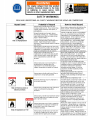
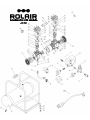
OILLESS AIR COMPRESSOR
OWNER’S MANUAL
WARNING
COMPRESSOR DISCHARGE AIR MAY CONTAIN HYDROCARBONS AND OTHER
CONTAMINANTS! DO NOT USE DISCHARGE AIR FOR BREATHING!
PARTS
Genuine ROLAIR replacement parts are sold nationwide through a network of authorized dealers and service
centers. Please contact the dealership where your air compressor was purchased or our factory Customer
Service Department if you need help troubleshooting, obtaining parts, or locating an authorized ROLAIR
service representative.
To order replacement parts:
1.
2.
3.
4.
5.
Give compressor model number
Give compressor serial number
Name of part
Part number
Quantity required
RECORD OF PERTINENT INFORMATION
Make a permanent record of the model and serial number of your new air compressor here. You’ll save time and
expense by including this reference information when requesting service or replacement parts.
Place & Date of Purchase
Model
Serial #
Volts
HZ
HP
With the tank gauge at 0 PSI and air line(s) disconnected, close drain valve(s) and record the amount of time it takes
to build tank pressure on the space provided. Periodically test your air compressor against this pump-up time to
determine if it is operating correctly. If time test is considerably off, contact your local ROLAIR representative to
arrange service.
Date
From 0 to ______*PSI
Min
Sec
Date
From 0 to ______*PSI
Min
Sec
606 South Lake Street > P.O. Box 346 > Hustisford, WI 53034-0346 > 920.349.3281 > fax 920.349.3691 > www.rolair.com
-1-
TABLE OF CONTENTS
Introduction and Definitions of Safety Warnings-------------------------------------------------------
2
Safety Warnings – Risk of Asphyxiation & Bursting----------------------------------------------------
3
Safety Warnings – Risk of Electrocution, Shock, Explosion, & Fire--------------------------------
3
Safety Warnings – Risk of Moving Parts, Burns, & Lifting---------------------------------------------
4
Safety Warnings – Risk of Propelled Objects, Unsafe Operation, and Damage---------------To Compressor or Property
Identification of System Controls---------------------------------------------------------------------------
4
Pre-Start Checklist----------------------------------------------------------------------------------------------
7
Operation----------------------------------------------------------------------------------------------------------
8
Maintenance------------------------------------------------------------------------------------------------------
9-10
Troubleshooting--------------------------------------------------------------------------------------------------
11
Guarantee---------------------------------------------------------------------------------------------------------
12
5-6
INTRODUCTION
Congratulations on the purchase of your new ROLAIR air compressor!
With over 50 years experience building ROLAIR air compressors specifically designed for the professional,
Associate Engineering Corporation has earned a reputation for providing a product unsurpassed in quality
and reliability. We are committed to continuing this tradition by analyzing and adapting to the changing
needs and rigorous demands of your industry. You can depend on ROLAIR because they are built to last.
This manual was compiled for the benefit of the operator. Do not use or allow anyone else to use your air
compressor until this manual is read and all safety/operating instructions are understood. By reading and
following the instructions contained in this manual, you can achieve years of trouble free service from your
new air compressor. If you have any additional safety or operating questions after reading this manual,
please contact your distributor or our customer service department. Do not remove or paint over any of
the warning decals attached to the compressor.
Definitions – Safety Warnings
Safety symbols are used throughout this manual to alert you to potentially hazardous situations. The
following definitions describe the level of severity for each signal word.
DANGER:
Indicates an imminently hazardous situation which, if not avoided,
WILL result in death or serious injury.
WARNING:
Indicates a potentially hazardous situation which, if not avoided,
COULD result in death or serious injury.
CAUTION:
Indicates a potentially hazardous situation which, if not avoided,
MAY result in minor or moderate injury or damage to the air
compressor.
-2-
SAFETY WARNINGS
READ AND UNDERSTAND ALL SAFETY WARNINGS BEFORE USING AIR COMPRESSOR
Hazard Level
Potential of Hazard
Serious injury or death may occur from
inhaling compressed air. The air stream may
contain carbon monoxide, toxic vapors, or
solid particles.
Sprayed materials such as paint, stucco,
insecticides, solvents, etc. contain harmful
vapors and poisons that may cause serious
injury or death if inhaled.
Risk of Asphyxiation
Risk of Bursting
Serious injury or death may occur if the
exhaust from gas-powered small engines is
inhaled. Engine exhaust fumes contain
poisonous, carbon monoxide which is odorless
and colorless.
Serious injury or death may occur from an air
tank explosion if the air tanks are not properly
maintained or if modifications, alterations or
repairs are attempted to the air receivers.
Serious injury or death may occur if
modifications are made to the pilot unloader
valve, pressure switch, safety relief valve or
other components that control the tank
pressure.
Serious injury may occur if accessories or
attachments are operated above the
manufacturer’s recommended pressure
ratings, causing them to explode or fly apart.
Serious injury or death could occur if the air
compressor is not properly grounded.
Electrical shock may occur if compressor is
not properly operated.
Risk of Electrocution or
Electrical Shock
Serious injury or death may occur if electrical
repairs are attempted by unqualified
personnel.
Serious injury or death may result from normal
electrical sparks that occur within the motor
and/or pressure switch.
Serious injury may occur if a fire is caused by
overheating due to inadequate ventilation or
restrictions to any of the compressors
ventilation openings.
Risk of Explosion or Fire
Serious injury or death may occur from a fire
or explosion if spilled gas or vapors come in
contact with hot engine parts and ignite.
-3-
How to Avoid Hazard
Never inhale compressed air directly from the
pump, receiver, or from a breathing device
connected to the air compressor.
Operate compressor only in a well-ventilated
area. Use a respirator device and follow the
manufacturer’s recommendations for their
spray equipment. Keep compressor at least
25 feet away from spray equipment.
Operate gas-powered compressors only in a
well-ventilated area. Avoid inhaling engine
exhaust fumes, and never run a small gaspowered engine in a closed building or
confined area without adequate ventilation.
Drain air tanks daily or after each use. Never
drill into, weld, patch or modify the air tanks.
If a leak develops, replace the tank
immediately or replace the entire compressor.
Never make adjustments to the components
that control tank pressure. Do not make
alterations to the factory operating pressure
settings. Check operation of the safety valve
on a regular basis and never operate without a
factory approved safety valve.
Do not use air tools or attachments before
reading the owner’s manual to determine the
maximum pressure recommendations. Never
exceed the manufacturer’s maximum
allowable pressure ratings. Do not use
compressor to inflate small low pressure
objects such as toys.
Always plug compressor into a properly
grounded outlet which provides correct
voltage, proper grounding and adequate fuse
protection.
Never operate air compressor in wet
conditions or outdoors when it’s raining. Do
not allow electric cords to lay in water. Do not
operate with damaged power cord or with
protective electrical covers removed. Do not
touch plug with wet hands. Do not pull on
electric cord to disconnect from the outlet.
Any electrical repairs or wiring performed on
this compressor should only be performed by
authorized service personnel in accordance
with the National and Local Electric Codes.
Always operate compressor in a wellventilated area free of combustible materials,
gasoline, flammable solvents or vapors.
Always locate compressor at least 20 feet
away from work area if spraying flammable
materials.
Never place objects against or on top of an air
compressor. Always operate air compressor
at least 18” away from any wall or obstruction.
Always operate in a clean, dry and wellventilated area.
Never attempt to fill the gas tank while the
engine is hot or running. Add fuel outdoors in
a well-ventilated area. Do not fill gas tank near
lit cigarettes or near other sources of ignition.
SAFETY WARNINGS
(con’t)
Serious injury may occur from moving parts
such as belts, pulleys, flywheels or fans if they
came in contact with you or your clothing.
An electric air compressor with automatic
controls can restart at any time and cause
bodily injury when least expected.
Risk from Moving Parts
Serious injury may occur if repairs are
attempted with damaged, missing or removed
protective guards, shrouds or missing covers.
Serious burn injuries could occur from
touching exposed metal parts such as the
compressor head, copper/braided discharge
lines and engine exhaust muffler during
operation, and even after compressor is shut
down for sometime.
Never operate the air compressor without
protective belt guards installed. Replace
damaged protective covers or guards
immediately.
Always unplug air compressor and drain air
tanks completely before attempting any
repairs or performing maintenance. Never
allow children or adolescents to operate air
compressor.
All repairs to the air compressor should be
made only by authorized or trained service
personnel.
Never touch any of the exposed metal parts
during operation and for an extended period of
time after the air compressor has shut down.
Do not attempt maintenance on the unit until
it has been allowed to completely cool.
Risk of Burn
Serious injury can result from attempting to lift
an object that is too heavy.
Always obtain assistance from others before
attempting to lift any object that is too heavy
for one person.
Risk of Injury from Lifting
Serious injury may occur from loose debris
being propelled at high speeds from the
compressed air stream.
Flying Objects
Warning
Risk of Unsafe Operation
Caution
Risk of Damage to
Air Compressor or Property
Serious injury or death may occur to you or
others if air compressor is used in an unsafe
manner.
Failure to transport or operate the air
compressor properly may result in major
repair expenses. Oil leaks will damage carpets,
painted surfaces, flooring and other items.
Always wear OSHA required “287” safety
glasses to protect the eyes during operation of
the air compressor. Never point the air stream
or tools at any point of your body, other
people or animals.
Always turn off the air compressor and drain
tank pressure completely before attempting
maintenance or attaching air tools.
Review and understand all instructions and
warnings in your owner’s manual. Know how
to stop the air compressor. Do not operate
until you are thoroughly familiar with all of the
controls. Do not operate the compressor if
fatigued or under the influence of alcohol or
drugs. Stay alert while operating the
compressor and pay close attention to the
task at hand.
Check oil levels daily and maintain proper oil
levels. Always run compressor in a level,
secure position that keeps it from tipping or
falling during use. Do not operate without an
air filter or in a corrosive environment.
Always transport in a level position and use
protective mats to keep truck beds clean, etc.
Check drain bolts regularly and do not overfill
machinery with oil.
Please note that this product may not be equipped with a spark arresting muffler. If the compressor is operated
around flammable materials or agricultural crops, brush, forests, and grasslands an approved spark arrestor must be
installed, maintained and in good working order. An approved spark arrestor is legally required in the State of
California under sections 4442 and 4443 of the California Public Resources Code Statute section 130050.
This product contains chemicals, including lead, known to the state of California to cause cancer, birth defects, and
other reproductive harm. Always wash hands after handling this product.
-4-
SYSTEM CONTROLS
(1) SAFETY-RELIEF VALVE Every ROLAIR air compressor is equipped with a safety-relief valve which is designed to discharge tank
pressure at a predetermined setting when a systems failure occurs. Check the safety valve periodically by pulling on the ring only
when the tank pressure is completely drained. The spring loaded valve should move freely within the safety valve body. An
inoperable safety valve could allow an excessive amount of tank pressure to build causing the air tank to catastrophically rupture
or explode.
Do not tamper with or attempt to eliminate the safety relief valve.
(2) MOTOR OVERLOAD PROTECTION Every ROLAIR electric air compressor is equipped with thermal overload protection. If the motor
overheats, an overload sensor will either trip a reset button or automatically break the circuit to protect the motor. Whenever your
air compressor unexpectedly stops running, unplug the power cord, drain the tank pressure completely and allow the motor to
cool for five to ten minutes before attempting to restart. Motors built with manual overload protection will trip a reset button that
must be physically pressed or pushed back into its original position before the motor can be restarted. Also note that motors with
automatic overload protection will attempt to restart if still plugged in, whenever the motor has sufficiently cooled. Always unplug
the compressor and drain tank pressure before attempting any type of repair.
The use of an undersized or excessive length of extension cord may be the cause of overheating. Always re-evaluate the
power source and gauge/length of extension cord being used when the motor overload stops the normal operation of your air
compressor. (Refer to chart on page 8.)
Motors with automatic overload protection can restart at any time.
(3) PRESSURE SWITCH Most electric air compressors are operated by the use of a pressure switch. Always make sure the lever
is in the “Off” position before plugging in the power cord. By moving the lever to the “On/Auto” position, the compressor will start
and stop automatically within the settings of the pressure switch. Do not attempt to stop the compressor by unplugging the
power cord. To stop, simply move the lever to the “Off” position.
(4) REGULATOR – WORKING PRESSURE To adjust the output/line pressure, simply rotate the regulator adjustment knob clockwise to
increase working pressure or counterclockwise to decrease. Never exceed the manufacturer’s maximum allowable pressure
rating of the tool being used or item being inflated.
(5) PRESSURE GAUGE(S) Typically, most compressors are designed with a gauge to measure tank or storage pressure and
another gauge attached to the regulator that indicates output or working pressure.
(6) DRAIN VALVE(S) One or more drain valves are installed to allow moisture to be drained on a daily basis from the compressor
storage tank(s). Open drains carefully and slowly to prevent scale, rust, or debris from becoming expelled at a high rate of speed.
(7) AIR INTAKE FILTER Air intake filters are installed to prevent foreign matter from entering the engine or compressor pump.
Check intake elements on a regular basis and either clean or replace as needed. Warm soapy water or low compressed air may
be used to clean the elements. Check intake canisters or elbow components for cracks or broken seals and replace if structural
problems are found.
(8) CHECK VALVE Every ROLAIR air compressor is built with a check valve to seal off and maintain tank pressure after the top
end setting of pressure switch is reached. The check valve works in conjunction with the solenoid relief valve to provide a loadless start for the compressor system. A quick burst of air escaping from the solenoid valve after the unit reaches top end indicates
the check valve is working properly. If the compressor has a mysterious leak after stopping that cannot be traced elsewhere, the
check valve may require servicing/replacing.
(9) VIBRATION DAMPENER(S) The rubber pads installed beneath every portable ROLAIR tank assembly are very important to the
proper operation of the air compressor. They provide protection from vibration that left unchecked could cause damage to many
system components. Always maintain the vibration dampeners on your air compressor.
(10) SOLENOID VALVE Your JC10 air compressor is equipped with an electronic solenoid valve which dumps head pressure
when your machine reaches top pressure or is unplugged. This type of unloading system provides a load-less restart when the
motor overload trips or even if your machine is unplugged while still building tank pressure.
-5-
PRE-START CHECKLIST
Read the owner’s manual thoroughly. Make sure that you completely understand all of the safety warnings,
system controls and instructions provided before attempting to operate this air compressor. Every effort has been
made to provide you with the information needed to obtain many years of reliable and trouble-free service out of
your new air compressor. It is your responsibility to operate the air compressor properly. To obtain the longest
possible service life from your air compressor you must always keep the following instructions in mind.
1. OPERATE IN A CLEAN, DRY AND WELL VENTILATED AREA
Allow at least 18” behind the belt guard for proper cooling of pump from flywheel blast. Do not operate in the rain
or in areas of standing water. Never operate in an area where other gases, fumes or vapors are present which
may become explosive when compressed. Do not operate compressor in an enclosed area.
2. INSPECT/CLEAN/CHANGE INTAKE ELEMENTS ON A REGULAR BASIS
The ingestion of dirt into the pump and engine is the primary cause of premature wear. Pay special attention to
the intake filters. Check intake filters daily.
3. USE LONGER PROPERLY SIZED AIR HOSE RATHER THAN EXTENSION CORDS
If an extension cord must be used, please refer to the chart below for the proper gauge and maximum length that
can be used. The use of inadequately sized air hose will also lead to frictional pressure drops that could affect the
proper performance of your air tools.
4. DO NOT USE A GENERATOR AS THE POWER SOURCE
Air compressors use inductive motors that require 3-5 times the full-load amp draw to properly start. Most
generators will not provide the wattage needed to properly start this type of electric motor.
5. CHECK TENSION OF BOLTS, BELTS, AND HARDWARE ON A REGULAR BASIS
Operation of any equipment with loose bolts and/or fittings will lead to excessive vibration
and the premature failure of the compressor system control components.
6. MAINTAIN RUBBER VIBRATION PADS
Excessive vibration is a major cause of premature compressor failure. Always maintain the rubber vibration pads
located beneath tank assembly. Operation without them will void your warranty.
7. DRAIN MOISTURE FROM AIR TANKS DAILY
Water is a natural byproduct of compressed air. Drain air tank(s) after each use to combat internal tank corrosion.
Keep drain valve(s) closed if storing compressor for any length of time.
ELECTRIC EXTENSION CORD TABLE
Minimum Wire Size
Extension
Cord Length
Up to 25 ft.
25 – 50 ft.
50 – 100 ft.
Motor
1/2 and 3/4 HP
14 Ga.
12 Ga.
10 Ga.
-6-
Motor
1, 1-1/2, and 2 HP
12 Ga.
10 Ga.
8 Ga.
OPERATION
WARNING – Your safety and the wellbeing of others during the operation of every ROLAIR compressor is our main
concern. Do not operate or permit anyone else to operate your air compressor until the information contained in this
manual is read and completely understood. Please contact your distributor or our customer service department if you
have any questions on the proper use of your air compressor.
DIRECT-DRIVE ELECTRIC
Establish that the air compressor is ready to operate by reviewing the topics and information provided in the “PreStart Checklist” section of this manual. Slowly open tank drain to remove any condensate that has accumulated and
keep drain open for a few seconds after starting to warm up motor/pump assembly. Make sure the pressure switch
lever is in the “Off” position before plugging power cord into a properly grounded outlet. Move pressure switch lever
to the “On/Auto” position to build and automatically maintain top end tank pressure setting. Rotate regulator
adjustment knob counterclockwise until the gauge attached reads 0 PSI before attaching air hose and accessory. Set
working pressure by rotating regulator adjustment knob clockwise and lock in working pressure according to
specifications provided by the tool manufacturer. Always use the pressure switch “On(Auto)/Off” lever to start or stop
the air compressor. Never stop the compressor by unplugging it from the power source. Store compressor in a
warm/dry location and perform maintenance as indicated in manual.
MAINTENANCE
Your new air compressor represents the finest engineering and construction available. Even the best
machinery requires periodic maintenance. Please stick to the maintenance schedule and consider the suggestions
that follow to keep your compressor in peak condition.
NOTE: Always unplug or shut down your compressor and drain the air tanks completely before attempting any
type of maintenance. Wait for compressor to cool before servicing.
MAINTENANCE HINTS:
1) Use a soap/water solution to check for air leaks.
2) Never clean filters with a flammable solvent.
3) Retorque head bolts only after pump has cooled.
4) Never weld on air tank(s).
7) Use heat to loosen Loctite seal on drain valves, engine
pulleys, and flywheels before attempting to remove.
MAINTENANCE SCHEDULE
Recommendation
Drain Moisture from Tank(s)
Inspect Air Filter(s)
Check for Unusual Noise or Vibration
Inspect Guards
Check for Air Leaks
Clean Exterior of Air Compressor
Check Condition of Vibration Pads
Tighten/Retorque Bolts
Check Operation of Safety Valve
Clean/Change Air Filter
Perform Pump Up Time Test
Check Operation of System Controls
Check Air Tanks for Dents/Leaks
Daily
X
X
X
X
X
Weekly
Monthly
Quarterly
X
X
X
X
X
X
X
X
-7-
TROUBLESHOOTING
WARNING - Make sure you completely understand all of the safety warnings and operation of each system
control component before attempting any maintenance or repair. Always drain the tank pressure completely, make
sure the power cord is unplugged, and unit has time to cool before performing any maintenance or service
operations.
PROBLEM
Pump is slow to build tank pressure
Knocking noise
Overheating compressor
Electric motor dead,
will not even hum
Motor trips overload/reset button
CAUSE
SOLUTION
Excessive leaks in system
Blown gasket
Broken reed valve
Obstructed intake filter
Leaking regulator
Internal pump problem
Poor ventilation
Improper pump rotation
Internal pump problem
Thermal overload tripped
Automatic overload has stopped
motor
Reset physically broken
Loose motor leads or electrical
connection
Short in power cord
Motor is starting/stopping
excessively
Overload is defective/weak
Correct air leaks
Replace head gaskets
Replace reed valves
Clean or replace intake element
Replace regulator
Take unit in for service
Relocate compressor
Contact an electrician
Take unit in for service
Locate and push reset button
Unplug, drain pressure and wait 5-10
minutes before attempting to restart
Replace overload/reset
Locate and correct loose electrical
connection(s)
Replace power cord
Install constant speed or dual control
kit
Replace overload
Use longer lengths of air hose or
heavier cord
Retighten or replace stripped thru
bolts
Take unit in for service
Improper gauge of extension cord
Stripped or poorly tightened motor
thru bolts
Cracks in end bell or housing
SPECIFICATIONS
MODEL JC10
Horsepower
1.0
Voltage
120 V
Hertz
60
Motor RPM
1680
Weight
39 lb.
Tank Size
2.3 gallons
Thermal Protection
Automatic
Dimensions
(L x W x H - inches)
Actual 15-5/8 x 16-3/4 x 14-3/4
Shipping 16-1/8 x 17-3/4 x 15-3/4
Cu. Ft. Delivered @ 40 PSI
3.8 CFM
Cu. Ft. Delivered @ 90 PSI
2.35 CFM
Decibels
60 dBA
Pump-Up Time (0-115 PSI) 45 seconds
Recovery Time (85-115 PSI) 11 seconds
-8-
Guarantee
Associate Engineering Corporation warrants that all ROLAIR compressors will be free of defects in
material and workmanship for a period of twelve months from the date of initial retail purchase, or
eighteen months from the date of manufacture, whichever may occur first.
Should any failure to conform to this warranty be reported to the company within said period, the
company shall, upon purchaser shipping the compressor to our plant transportation prepaid, correct
such nonconformity by suitable repair or, at its option, furnish a replacement part F.O.B. our plant.
Associate Engineering Corporation shall not be liable for any unauthorized repairs, replacements,
adjustments to the compressors, or the costs of labor performed by the purchaser.
This warranty is expressly in lieu of all other warranties expressed, implied or statutory (including,
but not limited to, warranties of merchantability and fitness for purpose) and of any other
obligations, and/or liabilities on the part of Associate Engineering Corporation. Associate
Engineering Corporation neither assumes nor authorizes any other person to assume for it any
other obligations or liability in connection with or with respect to any compressor.
Associate Engineering Corporation shall in no event be liable neither for any consequential, incidental
or special damages nor for the improper selection of any compressor for a particular application.
Quality
Associate Engineering Corporation is devoted to continual quality control and thorough
research of the products we build. It is our creed to give you, the user, all of the
experience and engineering available in the production of every piece of equipment we
produce.
Our line covers the complete needs of today’s varied air requirements. Rely on ROLAIR for
all the newest and finest features that are available for the modern compressor.
606 South Lake Street > P.O. Box 346 > Hustisford, WI 53034-0346 > 920.349.3281 > fax 920.349.3691 > www.rolair.com
4/11
-9-
PARTS LIST FOR MODEL JC10
Schem
#
1
2
3
4
5
6
7
8
9
10
11
12
13
14
15
16
17
18
19
20
21
22
23
24
25
26
27
28
29
30
Description
Part #
Motor Cover
Fan (left side only)
Crankcase (left side only)
Connecting Rod
Piston Ring
Piston Cap
Cap Bolt
Cylinder
O-Ring
Head Gasket
Head
Head Bolt
O-Ring
Connecting Tube
Bolt
Valve Stop
Valve – Exhaust
Valve Plate
Valve – Intake
Washer
Fan (right side only)
Eccentric
Bearing
Setscrew
Bolt – Con Rod
Crankcase (right side only)
Box Connector
Bolt
Bolt
Washer
JC800-1
JC800-2
JC800-3
JC800-4
JC800-5
JC800-6
JC800-7
JC800-8
JC800-9
JC800-10
JC800-11
JC800-12
JC800-13
JC800-14
JC800-15
JC800-16
JC800-17
JC800-18
JC800-19
JC800-20
JC800-21
JC800-22
JC800-23
JC800-24
JC800-25
JC800-26
JC800-27
JC800-28
JC800-29
JC800-30
Qty.
2
1
1
2
2
2
2
2
2
2
2
12
4
2
2
2
2
2
2
2
1
2
2
2
2
2
1
2
2
4
Schem
#
31
32
33
34
35
36
37
38
39
40
41
42
43
44
45
46
47
48
49
50
51
52
53
54
55
56
57
58
59
60
Description
Part #
Stator
Nut
Rotor
Bearing
Screw
Screw
Elbow
Air Filter Assembly
Vibration Dampener
Nut
Coupler
Regulator
Gauge – Line
Gauge – Tank
Bushing
Nipple
Safety Relief Valve
Pressure Switch
Capacitor
Cover – Capacitor
Check Valve
Solenoid – Unloader
Braided Discharge Line
Tank Assembly
Handle Grip
Rubber Foot
Washer
Bolt
Drain Valve
Cord with Plug
JC800-31
JC800-32
JC800-33
JC800-34
JC800-35
JC800-36
JC800-37
JC800-38
JC800-39
JC800-40
JC800-41
JC800-42
JC800-43
JC800-44
JC800-45
JC800-46
JC800-47
JC800-48
JC800-49
JC800-50
JC800-51
JC800-52
JC800-53
JC800-54
JC800-55
JC800-56
JC800-57
JC800-58
JC800-59
JC800-60
Qty.
1
4
1
2
4
2
1
1
4
4
1
1
1
1
1
1
1
1
1
1
1
1
1
1
1
4
4
4
1
1
606 South Lake Street > P.O. Box 346 > Hustisford, WI 53034-0346 > 920.349.3281 > fax 920.349.3691 > www.rolair.com
3/11