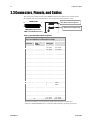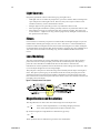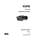
1
Line Scan CCD Cameras P2-2x-xxx40, P2-4x-xxx40, P2-2x-xxx30 Camera User’s Manual Revised 5/4/2011 10:27:00 AM 4-May-11 03-032-00493-14 www.teledynedalsa.com 2 Piranha 2 User’s Manual © 2011 Teled yne DALSA. All inform ation provid ed in this manual is believed to be accurate and reliable. N o responsibility is assum ed by Teled yne DALSA for its use. Teled yne DALSA reserves the right to make changes to this inform ation w ithout notice. Reprod uction of this manual in w hole or in part, by any m eans, is prohibited w ithout prior perm ission having been obtained from Teled yne DALSA. About Teledyne Technologies and Teledyne D ALSA, Inc. Teled yne Technologies is a lead ing provid er of sophisticated electronic subsystem s, instrum entation and com m unication prod ucts, engineered system s, aerospace engines, and energy and pow er generation system s. Teled yne Technologies’ operations are prim arily located in the United States, the United Kingd om and Mexico. For more inform ation, visit Teled yne Technologies’ w ebsite at w ww .teled yne.com . Teled yne DALSA, a Teled yne Technologies com pany, is an international lead er in high performance d igital im aging and sem icond uctors w ith approxim ately 1,000 em ployees world w id e, headquartered in Waterloo, Ontario, Canada. Established in 1980, the com pany d esigns, d evelops, m anufactures and m arkets d igital im aging prod ucts and solutions, in ad d ition to provid ing MEMS prod ucts and services. For m ore information, visit Teled yne DALSA’s w ebsite at ww w .teled yned alsa.com . Support For further inform ation not included in this manual, or for inform ation on Teled yne DALSA’s extensive line of im age sensing prod ucts, please contact: N orth America Europe Asia Pacific 605 McMurray Rd Waterloo, ON N2V 2E9 Canada Breslauer Str. 34 Ikebukuro East 13F D-82194 Gröbenzell (Munich) 3-4-3 H igashi-Ikebukuro Germ any Toshim a-ku, Tokyo 170-0013 Tel: +49 - 8142 – 46770 Japan w w w.teled ynedalsa.com Fax: +49 - 8142 – 467746 Tel: 81 3 5960 6353 sales.am ericas@teled yned alsa.com w w w.teled ynedalsa.com Fax: 81 3 5960 6354 (fax) support@teled yned alsa.com sales.europe@teled ynedalsa.com w w w.teled ynedalsa.com support@teled yned alsa.com sales.asia@teled yned alsa.com Tel: 519 886 6000 Fax: 519 886 8023 support@teled yned alsa.com Cam era Link is a trad emark registered by the Autom ated Im aging Association, as chair of a com m ittee of ind ustry m em bers includ ing Teled yne DALSA. 03-032-00493-14 Teledyne DALSA 3 Piranha 2 User’s Manual Contents Introduction to the Piranha 2 Line Scan Camera __________________________________ 5 1.1 Camera Highlights ....................................................................................................................................................... 5 1.2 Image Sensors ............................................................................................................................................................. 7 1.3 Camera Performance Specifications ............................................................................................................................ 8 Camera Hardware Interface ________________________________________________ 13 2.1 Installation Overview ................................................................................................................................................... 13 2.2 Input / Output .............................................................................................................................................................. 13 2.3 Connectors, Pinouts, and Cables .................................................................................................................................. 14 2.4 Power Supplies ............................................................................................................................................................ 16 2.5 Control Inputs, Camera Link ........................................................................................................................................ 16 2.6 Data Bus, Camera Link................................................................................................................................................ 17 2.7 Timing ......................................................................................................................................................................... 19 2.8 Camera Link Serial Communication ............................................................................................................................ 22 Software Interface: How to Control the Camera __________________________________ 23 3.1 Overview ...................................................................................................................................................................... 23 3.2 Command Format ........................................................................................................................................................ 23 3.3 Processing Chain .......................................................................................................................................................... 24 3.4 Startup ......................................................................................................................................................................... 25 3.5 Saving and Restoring Settings ..................................................................................................................................... 25 3.6 Setting Baud Rate ........................................................................................................................................................ 26 3.7 Setting the Data Mode ................................................................................................................................................. 26 3.8 Setting the Video Mode ............................................................................................................................................... 27 3.9 Setting Line Rate and Exposure Mode ......................................................................................................................... 27 3.10 Setting a Region of Interest ....................................................................................................................................... 29 3.11 Returning Video Information .................................................................................................................................... 29 3.12 Optimizing Offset Performance ................................................................................................................................. 31 3.13 Setting Gains ............................................................................................................................................................. 34 3.14 How to Calibrate the Camera .................................................................................................................................... 35 3.15 Setting and Reading FPN Coefficients ....................................................................................................................... 38 3.16 Setting and Reading PRNU Coefficients .................................................................................................................... 39 3.17 Generating Test Patterns ........................................................................................................................................... 39 3.18 Monitoring the Camera ............................................................................................................................................. 40 3.19 Rebooting the Camera ............................................................................................................................................... 41 3.20 Setting the Pre-trigger .............................................................................................................................................. 41 Optical, Mechanical, and Thermal Considerations _________________________________ 43 4.1 Mechanical Interface .................................................................................................................................................... 43 4.2 Optical Interface .......................................................................................................................................................... 47 03-032-00493-14 Teledyne DALSA 4 Piranha 2 User’s Manual 4.3 Compliance .................................................................................................................................................................. 49 CCD Handling Instructions _________________________________________________ 51 5.1 Electrostatic Discharge and the CCD Sensor ................................................................................................................ 51 5.2 Protecting Against Dust, Oil and Scratches .................................................................................................................. 51 5.3 Cleaning the Sensor Window ....................................................................................................................................... 52 Troubleshooting ________________________________________________________ 53 6.1 Common Solutions ....................................................................................................................................................... 53 6.2 Troubleshooting Using the Serial Interface ................................................................................................................. 54 6.3 Specific Solutions ......................................................................................................................................................... 55 Camera Link™ Reference _________________________________________________ 59 EMC Declaration of Conformity ______________________________________________ 61 Communications Protocol _________________________________________________ 63 C1 Protocol Overview ......................................................................................................................................................... 63 C2 Protocol Features .......................................................................................................................................................... 63 C3 Command Format and Examples ................................................................................................................................. 63 C4 Networking Mode ......................................................................................................................................................... 64 C5 Error Handling .............................................................................................................................................................. 67 C6 Camera Parameter Screen ........................................................................................................................................... 70 C7 Commands .................................................................................................................................................................... 73 DC Offset De-rating Curve _________________________________________________ 79 Revision History ________________________________________________________ 81 Index _______________________________________________________________ 85 03-032-00493-14 Teledyne DALSA 5 Piranha 2 User’s Manual 1 Introduction to the Piranha 2 Line Scan Camera 1.1 Camera Highlights Features • • • • • • • • • • • Data rates u p to 160MH z Resolu tions from 1k to 8k for 40MH z m od el Resolu tions from 1k to 8k for 30MH z m od el H igh resp onsivity Exposu re control and antibloom ing Pinned photod iod e sensor for low im age lag Program m able integration tim e, line rate, gain, offset, bit d epth, test p attern, and d iagnostics Flat-field correction—m inim izes sensor FPN and PRN U, lens vignetting and non u niform lighting Cam era Link™ interface Single 12V to 15V p ow er su p ply Com pact d esign Performance • • • • • 03-032-00493-14 4x40MH z qu ad ou tpu t d ata rate, 2x40MH z d u al ou tpu t d ata rate w ith 40MH z m od el 2x30MH z d u al ou tpu t d ata rate w ith 30MH z m od el 8 or 10-bit ou tpu t from 10-bit d igitization 1024, 2048, and 4096 p ixels, 10µm x 10µm , and 4096, 6144 and 8192 pixels, 7m x 7m , 100% fill factor Line rates u p to 65kH z Teledyne DALSA 6 Piranha 2 User’s Manual Programmability • • Sim ple ASCII protocol controls gain, offset, line rates, trigger m od e, pixel correction, test pattern ou tpu t, and cam era d iagnostics. Serial interface (ASCII, 9600 bau d , ad ju stable to 19200, 57600, 115200), throu gh Cam era Link. Usability • • • • Program m able gains, offsets, and cam era controls End -of-line sequ ence and test pattern ou tpu t for d ebu gging Single inpu t su pply (+12V to +15V) Com pliant w ith CE and MIL-STD-810E (shock and vibration) Description Piranha 2 takes perform ance to a new level. Tw o and fou r 8 or 10-bit ou tpu ts (selectable) at u p to 40MH z d eliver u p to 160MH z throu ghpu t. Available in 1k to 8k resolu tions, Piranha 2 is sm all, light, and u ses a single voltage pow er su pp ly. Cabling and interface are sim plified w ith the Cam era Link high -speed serial stand ard . The cam era is sensitive, but still provid es qu iet, u niform ou tpu t thanks to CDS (correlated d ou ble sam pling) and em bed d ed flat-field correction algorithm s. Gain and offset are fu lly program m able for each ou tpu t channel, and the cam era can ou tpu t test patterns for cable/ system trou bleshooting. All resolu tions provid e app ropriate, read ily available stand ard lens options (C-m ou nt, F-m ou nt, and M72x0.75 large form at photograp hy stand ard s). All these featu res com bine to m ake Piranha 2 the m ost p ow erfu l line scan cam era in the w orld . Set it loose on you r tou ghest im aging challenge. Applications The Piranha 2 is id eal for ap plications requ iring high speed , su perior im age qu ality, and high responsivity. Ap plications inclu d e: 03-032-00493-14 Electronics m anu factu ring inspection Postal/ parcel sorting H igh perform ance d ocu m ent scanning/ im age lift N arrow and large w eb inspection H igh-end ind u strial inspection Teledyne DALSA 7 Piranha 2 User’s Manual 1.2 Image Sensors The im age sensor u sed in you r cam era d epend s on the cam era’s resolu tion and nu m ber of tap s. 1k, 2k, 4k (10 µm ), 2 tap s: IL-P1 (Figu re 1) 2k, 4k (10 µm ), 4 taps: IT-P1 (Figu re 2) 4k (7 µm ), 6k, 8k, 2 tap s: IL-P4 (Figu re 3) 4k (7 µm ), 6k, 8k, 4 tap s: IT-P4 (Figu re 4) Figure 1: IL-P1 Image Sensor (1k, 2k, 4k (10 µm), 2 tap models) CR1S, CR2S, CR1B, CR2B, CRLAST OS2 5I CCD Readout Shift Regist er 4I Stor ageWell with Exposure Control and Reset Structure 32 S 4I N Pinned Photodiodes (10µm x 10µm) 4I TCK 32 S VSTOR PR VPR Stor ageWell with Exposure Control and Reset Structure VDD 5I VBB RST VSET VOD OS1 1 CCD Readout Shift Regist er 4I 32 S Light-shielded pixels 4 I Isolation pixels N = 1024 or 2048 CR1S, CR2S, CR1B, CR2B, CRLAST VSS Relative position of package Pin 1 Figure 2: IT-P1 4k Image Sensor (2k, 4k (10 µm), 4 tap models) Relative position 1 of package Pin 1 N=2048 or 4096 03-032-00493-14 Teledyne DALSA 8 Piranha 2 User’s Manual Figure 3: IL-P4 Image Sensor (4k (7µm), 6k, and 8k, 2 tap models) CR1, CR2, CRLAST OS2 5I CCD Readout Shift Regist er 4I Stor ageWell with Exposure Control and Reset Structure 32 S 4I N Pinned Photodiodes (7µm x 7µm) 4I TCK 32 S VSTOR PR VPR Stor ageWell with Exposure Control and Reset Structure VDD 5I VBB RST VSET VOD OS1 1 CCD Readout Shift Regist er 4I 32 S Light-shielded pixels 4 I Isolation pixels N = 4096, 6144 or 8192 CR1, CR2, CRLAST VSS Relative position of package Pin 1 Figure 4. IT-P4 Image Sensor (4k (7µm), 6k, and 8k, 4 tap models) CR1, CR2, CRLAST-L OS2 CR1, CR2, CRLAST-R 5I CCD Readout Shift Regist er OS4 5I Stor ageWell with Exposure Control and Reset Str ucture 32 S 4I N Pinned Photodiodes (7µm x 7µm ) 4I TCK 32 S VSTOR PR VPR Stor ageWell with Exposure Control and Reset Str ucture 5I CCD Readout Shift Regist er CR1, CR2, CRLAST-L 5I 32 S Light-shielded pixels 4 I Isolation pixels N = 4096, 6144 or 8192 CR1, CR2, CRLAST-R VDD VDD VBB OS1 RST-L VSET-L VOD-L Relative position 1 of package Pin 1 VSS-L VSET-R VBB RST-R VOD-R VSS-R OS3 1.3 Camera Performance Specifications The follow ing tw o tables list the cam era’s perform ance sp ecifications. The first table lists the operating ranges of the cam era, and the second table lists the perform ance specifications at m inim u m , nom inal and m axim u m gain levels at 1kH z d ata rate. N ote that as gain levels increase, p erform ance d ecreases, becau se you r signal to noise d ecreases. Also note that the cam eras p erform ance specifications w ere obtained u sing a line rate of only 1kH z. At low line rates, d ark cu rrent can becom e a significant sou rce of noise and ap pears in specifications su ch as FPN , PRN U and noise. If you operate the cam era at faster line rates, su ch as 10kH z or greater, the am ou nt of d ark cu rrent w ill be red u ced by 10x or greater. 03-032-00493-14 Teledyne DALSA 9 Piranha 2 User’s Manual Table 1. Piranha 2 Operating Requirements and Ranges Operating Requirements Units Typical Notes Pow er 1024—2 o/ p 2048—2 / 4 o/ p 4096 (7µm )—2 / 4 o/ p 4096 (10µm )—2 o/ p 4096 (10µm )—4 o/ p 6144—2 / 4 o/ p 8192 —2 / 4 o/ p Pow er Supply Current (Vin = +12V) 1024—2 o/ p 2048—2 / 4 o/ p 4096—2 / 4 o/ p 4096 (10µm )—2 o/ p 4096 (10µm )—4 o/ p 6144—2 / 4 o/ p 8192 —2 / 4 o/ p W W W W W W W 6 6 / 8.5 6 / 8.5 7.5 9.6 7.5 / 9.6 7.5 / 10 mA mA mA mA mA mA mA 480 500 / 500 / 600 800 600 / 620 / Tim e to pow er up, typ Tim e to calibrate (FPN / PRN U) 1024 2048 4096 6144 8192 sec. 15 sec. sec. sec. sec. sec. 10 19 38 85 115 Specification Units Min Max Notes Data Rate, per tap (40 MH z m od el) (30 MH z m od el) MH z MH z 40 30 40 30 1 Specification Units Min 700 700 800 840 Max 30 MHz Max 40 MHz 49.6 27 65.3 35.4 68 18.5 36.2 12.3 24.4 9.3 18.6 Line Rate 1024, 2 o/ 2048, 2 o/ 2048, 4 o/ 4096, 2 o/ 4096, 4 o/ 6144, 2 o/ 6144, 4 o/ 8192, 2 o/ 8192, 4 o/ p p p p p p p p p Tem perature Front plate Tem perature Tem perature d rift before recalibration (recom m end ation) Sensor Alignm ent 03-032-00493-14 kH z kH z kH z kH z kH z kH z kH z kH z kH z °C °C 1 1 1 1 1 1 1 1 1 10 14 7.15 50 10 1 1 1 1 2 Teledyne DALSA 10 Piranha 2 User’s Manual Specification Units x,y z z um mm ° Min Max Notes ±175 ±0.25 ±0.6 N ote that the environm ent cond itions represent the state of the environm ent w hen the cam era w as being tested . Typical resu lts are the average valu es obtained w ith at a 1kH z line rate and 30°C. Maxim u m resu lts represent the w orst case resu lts from any cam era operating at 50°C w ith a 1kH z line rate. 03-032-00493-14 Teledyne DALSA 11 Piranha 2 User’s Manual Typ Max Notes 40 1 0 40 1 0 40 40 1 +10 30 50 40 1 +1 0 50 3 18 28 5 10 23 28 DN 15 38 16 38 PRN U corrected ECD/ ECE DN 1.5 / 2 3/ 3 1.2/ 1.5 DC Offset 4k and und er 6k and over DN 2 2 3 3 5 5 6K and 8K, ECD/ ECE 3.4 6.8 3.8 7.6 2 0.5 1.1 1.6 0.3 DN DN 30 Max Max 5 9 3 6 496:1 2 DN / (nJ/ cm ) 2 DN / (nJ/ cm ) Ratio DN DN DN DN DN +10 Typ Typ 12 24 3 0.5 4 4 2 10.7 21.4 390:1 4 0.75 3.5 4 1 Broad band Responsivity, 7um pixels Broad band Responsivity, 10um pixels Dynam ic Range Pk-Pk N oise, m ax RMS N oise, m ax FPN uncorrected , m ax 4K and und er FPN uncorrected , m ax 6K and over FPN corrected , m ax PRN U uncorrected 1K and 2K, ECD/ ECE 4k, ECD/ ECE Typ 9.4 18.8 207:1 Electro-Optic Specifications Min Min 0 30 60 62:1 34 68 135:1 15 2.2 8 14 2 38 76 39 43 3/ 8 8/ 10 12/ 2 0 14/ 2 7 2/ 3. 5 5/ 27 2 5 5 7 14 17 17 6 6 8 1.2 8 8 2 32 4 27 27 8 DN = Digital N u m bers (0-255); also know n as gray levels. ECE = Exposu re Control Enabled ECD = Exposu re Control Disabled 1. 2 3 4 5 6. 03-032-00493-14 4 4 5 5 2 55 N otes: • • • Notes Min 50 40 Min 30 -10 Max 40 1 -10 Typ 40 1 -10 Max. Gain Min Max °C 40 Max Front Plate Tem perature Typ MH z kH z dB Units Data Rate (40MH z m od el) Line Rate Gain Setting Min Environment Conditions Units Table 2. Piranha2 Performance Specifications, 1kHz line rate, 40MHz Model Min. Gain Nom. Gain All m easu rem ents taken in 8-bit ou tpu t m od e. All m easu rem ents are valid for front p late tem peratu res in still air. All m easu rem ents u sed a Tu ngsten halogen light sou rce, 3200K bu lb tem p., and 750nm cu toff filter All specifications for the 30MH z m od el are prelim inary. Du e to FPN / PRN U correction calcu lations, certain d igital nu m bers w ill be u navailable w hen ou tpu tting 10 bits w ith FPN / PRN U correction. Measu red at front p late. The correspond ing am bient tem p eratu re range w ith still air is 0°C - 37°C. Measu rem ents taken at m axim u m line rates. Exposu re control enabled to set the m axim u m integration tim e to 200 m icrosecond s. Refer to Ap pend ix D for DC Offset d e-rating cu rves. Teledyne DALSA 12 Piranha 2 User’s Manual Figure 5: P2 Responsivity 2 Responsivity [DN/(nJ/cm )] Responsivity, Nominal Gain 03-032-00493-14 24 10µm pixels 20 16 12 7µm pixels 8 4 0 400 500 600 700 800 900 1000 Wavelength (nm) Teledyne DALSA 13 Piranha 2 User’s Manual 2 Camera Hardware Interface 2.1 Installation Overview In ord er to set u p you r cam era, you shou ld take these steps: 1. Connect Cam era Link™ cables from cam era to fram e grabber. 2. Connect pow er. You m u st also set u p the other com ponents of y ou r system , inclu d ing light sou rces, fram e grabbers, cam era m ou nts, heat sinks, host com pu ters, optics, encod ers, and so on. 2.2 Input / Output Camera Link™ (2 and 4Tap models) Camera Link™ (4Tap model only) Diagnostic LED (See section 3.18) +12V to +15V and Ground ! 03-032-00493-14 WARNING: It is extremely important that you apply the appropriate voltages to your camera. Incorrect voltages w ill damage the camera. See section 2.4 for more details. Teledyne DALSA 14 Piranha 2 User’s Manual 2.3 Connectors, Pinouts, and Cables The cam era u ses a high -d ensity 26-pin MDR26 connector for Cam era Link control signals, d ata signals, and serial com m u nications, and a 6-pin H irose connector for pow er. M D R 26F em a le 13 1 26 14 Base, Medium, and Full Configuration Medium and Full Configuration Only M atingP art:3M334-31series Cable: 3M14X26-S ZLB -XXX-0LC** Table 3: Camera Link Medium and Full Configuration Medium and Full Configurations Up to an additional 2 Channel Link Chips Camera Right Angle Channel Cable Name Connector Frame Link Signal Grabber 1 1 inner shield Inner Shield 14 14 inner shield Inner Shield 2 25 Y0- PAIR1- 15 12 Y0+ PAIR1+ 3 24 Y1- PAIR2- 16 11 Y1+ PAIR2+ 4 23 Y2- PAIR3- 17 10 Y2+ PAIR3+ 5 22 Yclk- PAIR4- 18 9 Yclk+ PAIR4+ 6 19 21 8 Y3Y3+ PAIR5PAIR5+ 7 20 100 ohm PAIR6+ 20 7 term inated PAIR6- 8 19 Z0- PAIR7- 21 6 Z0+ PAIR7+ 9 18 Z1- PAIR8- 22 5 Z1+ PAIR8+ 10 17 Z2- PAIR9+ 23 4 Z2+ PAIR9- 11 16 Zclk- PAIR10- 24 3 Zclk+ PAIR10+ 12 15 Z3- PAIR11+ 25 2 Z3+ PAIR11- 13 26 13 26 inner shield inner shield Inner Shield Inner Shield *Exterior Overshield is connected to the shells of the connectors on both end s. **3M part 14X26-SZLB-XXX-0LC is a com plete cable assem bly, inclu d ing connectors. 03-032-00493-14 Teledyne DALSA 15 Piranha 2 User’s Manual Table 4: Camera Link Base Configuration Base Configuration One Channel Link Chip + Camera Control +Serial Communication Camera Connector Right Angle Channel Link Frame Grabber Signal 1 1 inner shield 14 14 inner shield 2 25 X0- 15 12 X0+ 3 24 X1- 16 11 X1+ 4 23 X2- 17 10 X2+ 5 22 Xclk- 18 9 Xclk+ 6 21 X3- 19 8 X3+ 7 20 SerTC+ 20 7 SerTC- 8 19 SerTFG- 21 6 SerTFG+ 9 18 CC1- 22 5 CC1+ 10 17 CC2+ 23 4 CC2- 11 16 CC3- 24 3 CC3+ 12 15 CC4+ 25 2 CC4- 13 13 inner shield 26 26 inner shield Unu sed pairs shou ld be term inated in 100 ohm s at both end s of the cable. Table 5: Camera Control Configuration Signal Configuration Pin CC1 EXSYN C 9, 22 CC2 PRIN 10, 23 CC3 Spare 11, 24 CC4 Spare 12, 25 See Ap pend ix B for the com plete Cam era Link configu ration table, and refer to the Know led ge Center page on the Teled yne DALSA Web site (w w w .teled yned alsa.com / m v/ know led ge/ appnotes.asp x) for the official Cam era Link d ocu m ents. 03-032-00493-14 Teledyne DALSA 16 Piranha 2 User’s Manual Hirose6-pinCircular M ale 6 1 5 2 4 3 MatingPart:HIROS E HR10A-7P-6S Pin Description Pin Description 1 +12V to +15V 4 GN D 2 +12V to +15V 5 GN D 3 +12V to +15V 6 GN D 2.4 Power Supplies The cam era requ ires a single voltage inpu t (+12V to +15V). The cam era m eets all perform ance specifications u sing stand ard sw itching p ow er su pplies, althou gh w ell regu lated linear su p plies provid e optim u m perform ance. See the Perform ance Specifications for cu rrent requ irem ents. When setting u p the cam era’s pow er su p plies follow these gu id elines: • • • Protect the cam era w ith a fast-blow fu se betw een pow er su pply and cam era. Do not u se the shield on a m u lti-cond u ctor cable for grou nd . Keep lead s as short as p ossible to red u ce voltage d ro p. See section 1.3 for pow er requ irem ents. ! WARNING: It is extremely important that you apply the appropriate voltages to your camera. Incorrect voltages will damage the camera. Protect the camera with a fast-blow fuse between power supply and camera. Visit http:/ / vfm .d alsa.com for a list of com p anies that m ake pow er su p plies that m eet the cam era’s requ irem ents. The com panies listed shou ld not be consid ered the only choices. Many high qu ality su pplies are available from other vend ors. We assu m e no resp onsibility for the u se of these su p plies. 2.5 Control Inputs, Camera Link The cam era accepts control inpu ts throu gh the Cam era Link MDR26F connector. All inputs are optional. The camera ships in exposure mode 2 and with a 5 kHz line rate. All Camera Control (CCx) signals are in a logic HIGH state. IMPORTANT: This camera uses the falling edge of EXSYNC to trigger line readout, unlike previous DALSA cameras, which used the rising edge. Line rate can be set internally u sing the serial interface. Pow er -on rate is alw ays 9600 bau d . Data rate for the 40MH z m od el is alw ays 40MH z. Data rate for the 30MH z m od el is alw ays 30MH z. The external control signals, EXSYN C and PRIN , are optional and enabled throu gh the serial interface. PRIN PRIN is an optional inpu t signal u sed for exposu re control (PRIN ). 03-032-00493-14 PRIN Indicates H igh Low Integration Pixel reset Teledyne DALSA 17 Piranha 2 User’s Manual EXSYNC (Triggers Line Readout) EXSYN C is an optional inpu t signal that can be u sed to trigger the line read ou t rate. This cam era u ses the falling edge of EXSYNC to trigger line read ou t. Note: EXSYN C shou ld not be clocked faster than the cam era’s specified m axim u m line rate. The cam era ignores the EXSYN C pu lse u ntil it has com pleted read ing the last line ou t. 2.6 Data Bus, Camera Link These signals ind icate w hen d ata is valid , a llow ing you to clock the d ata from the cam era to you r acqu isition system . These signals are p art of the Cam era Link configu ration and you shou ld refer to the Cam era Link Im plem entation Road Map, available from the Know led ge Center page on the Teled yne DALSA w ebsite (w w w .teled yned alsa.com / m v/ know led ge/ appnotes.asp x) for the stand ard location of these signals: Clocking Signal Indicates LVAL (high) DVAL (high) STROBE (rising ed ge) Outputting valid line Valid d ata Valid d ata IMPORTANT: This cam era’s d ata sh ou ld be sam pled on the rising edge of STROBE. Digital Data The cam era d igitizes internally to 10 bits and ou tpu ts either all 10 bits or the m ost significant 8 bits in LVDS form at on the Cam era Link connector. Note: Du e to flat-field correction calcu lations, certain d igital nu m bers w ill be u navailable w hen ou tpu tting 10 bits w ith flat-field correction enabled (i.e. you w ill experience m issing cod es). 03-032-00493-14 Teledyne DALSA 18 Piranha 2 User’s Manual Test Pattern Pixels and End-of-line Sequence For information on the test pattern and end of line sequence commands, see section 3.17 Generating Test Patterns. To facilitate system -level d ebu gging and verification of d ata path integrity, the cam era can generate a test p attern. The test pattern is a ram p from 0 to 255DN , then starts at 0 again. Use the test p attern to verify the proper tim ing and connections betw een the cam era and the fram e grabber. To alleviate post-processing, Piranha 2 offers an end -of-line sequ ence that provid es basic calcu lations inclu d ing "line cou nter", "line average", "pixels above threshold ", "pixels below threshold ", and "d erivative line su m ". These basic calcu lations are the center of m ost au tom atic gain control (AGC) algorithm s. To fu rther aid in d ebu gging and cable/ d ata p ath integrity, the first six bits of the ou tp u t of the end -of-line sequ ence are "aa", "55", "aa". Refer to the table below . 03-032-00493-14 Location Value Description 1 A’s 2 5’s By ensuring these values consistently toggle betw een "aa" and "55", you can verify cabling (i.e. no stuck bits) 3 A’s 4 4 bit counter LSB justified Counter increm ents by 1. Use this value to verify that every line is output 5 Line sum LSB Use these values to help calculate line average 6 Line sum MID 7 Line sum MSB 8 0 9 Pixels above threshold LSB 10 Pixels above threshold MSB 11 Pixels below threshold LSB 12 Pixels below threshold MSB 13 Derivative line sum LSB 14 Derivative line sum Mid 15 Derivative line sum MSB 16 0 Monitor these values (either above or below threshold ) and ad just cam era gain to keep these values relatively constant. This provid es a basis for autom atic gain control (AGC) Use these values to focus the cam era. Generally, the greater the sum the greater the im age contrast Teledyne DALSA 19 Piranha 2 User’s Manual 2.7 Timing Figure 6. Piranha 2 Overview Timing Showing Input and Output Relationships Figure 7. Piranha 2 Fixed (Programmed) Integration Timing with External EXSYNC 03-032-00493-14 Teledyne DALSA 20 Piranha 2 User’s Manual Table 6: Piranha 2 40MHz Timing (Fixed Integration Mode) Symbol Definition 03-032-00493-14 tw SYN C The m inim um low w id th of the EXSYN C pulse w hen not in SMART EXSYN C m od e. tw SYN C (SMART)* The m inim um low w id th of the EXSYN C pulse w hen in SMART EXSYN C m od es to guarantee the photosites are reset. Min (ns) Typ (ns) Max (ns) 100 2,000 tw SYN C_IN T The m inim um w id th of the high pulse w hen the ―SMART EXSYN C‖ feature is turned off 100 tw SYN C_IN T (SMART) * Is the integration tim e w hen the ―SMART EXSYN C‖ feature is available and turned on. N ote that the m inim um tim e is necessary to guarantee proper operation. tLIN E PERIOD (t LP) The m inim um and m axim um line tim es m ad e up of tTransfer, tREADOUT plus tOVERH EAD to m eet specifications. 53,190 (8K4T) 106,382 (8K2T) 40,485 (6K4T) 80,645 (6K2T) 27,624 (4K4T) 54,054 (4K2T) 28,248 (2K2T) 15,313 (1K2T) tTransfer The tim e from the reception of the falling ed ge of EXSYN C to the rising ed ge of LVAL w hen pretrigger is set to zero. Pretrigger red uces the num ber of clocks to the rising ed ge of LVAL but d oesn’t change the tim e to the first valid pixel. If the fixed integration tim e m od e of operation is available and selected then the integration tim e is ad d ed to the specified value. 1,420 +/ -50 tw Fixed Int. Fixed Integration Tim e m od e of operation for variable exsync frequency. 800 tREADOUT Is the num ber of pixels per tap tim es the read out clock period . Pretrigger = 0. 51,200 (8K4T) 102,400 (8K2T) 38,400 (6K4T) 76,800 (6K2T) 25, 600 (4K4T) 51,200 (4K2T) 25,600 (2K2T) 12,800 (1K2T) tOVERH EAD Is the num ber of pixels that m ust elapse after the falling ed ge of LVAL before the EXSYN C signal can be asserted . This tim e is used to clam p the internal analog electronics 540+/ -50 thPR Applies w hen the PRIN exposure control feature is enabled . The PRIN signal m ust be held a m inim um tim e after the EXSYN C falling ed ge to avoid losing the integrated charge 0 tw PR_LOW Minim um Low tim e to assure com plete 2,000 +/ - 200 2,000 6 10 t LP – 2,000 Teledyne DALSA 21 Piranha 2 User’s Manual Symbol Definition Min (ns) Typ (ns) Max (ns) photosite reset tPR_SET The nom inal tim e that the photo sites are integrating. Clock synchronization w ill lead to integration tim e jitter, w hich is show n in the specification as +/ - values. The user should com m and tim es greater than these to ensure proper charge transfer from the photosites. Failure to m eet this requirem ent m ay result in bloom ing in the H orizontal Shift Register. 2,000+/ -200 *SMART EXSYN C refers to exposu re m od e 4. Refer to section 3.9 Setting Line Rate and Exposu re Mod e for fu rther inform ation on exposu re m od es. Table 7: Piranha 2 30MHz Timing (Fixed Integration Mode) N ote: All valu es are p relim inary for the Piranha 2 30MH z Symbol Definition Min (ns) tw SYN C The m inim um low w id th of the EXSYN C pulse w hen not in SMART EXSYN C m od e. 132 tw SYN C (SMART)* The m inim um low w id th of the EXSYN C pulse w hen in SMART EXSYN C m od es to guarantee the photosites are reset. 03-032-00493-14 Max (ns) 2,640 tw SYN C_IN T The m inim um w id th of the high pulse w hen the ―SMART EXSYN C‖ feature is turned off tw SYN C_IN T (SMART) * Is the integration tim e w hen the ―SMART EXSYN C‖ feature is available and turned on. N ote that the m inim um tim e is necessary to guarantee proper operation. 2,000 tLIN E PERIOD (t LP) The m inim um and m axim um line tim es m ad e up of tTransfer, tREADOUT plus tOVERH EAD to m eet specifications. 140487 (8K2T) 70,170 (4K2T) 36,378 (2K2T) 19,483 (1K2T) tTransfer The tim e from the reception of the falling ed ge of EXSYN C to the rising ed ge of LVAL w hen pretrigger is set to zero. Pretrigger red uces the num ber of clocks to the rising ed ge of LVAL but d oesn’t change the tim e to the first valid pixel. If the fixed integration tim e m od e of operation is available and selected then the integration tim e is ad d ed to the specified value. 1,874 +/ -66 tw Fixed Int. Fixed Integration Tim e m od e of operation for variable exsync frequency. 800 Is the num ber of pixels per tap tim es the read out clock period . Pretrigger = 0. 138033 (8K2T) 33, 792 (4K4T) 67,584 (4K2T) 33,792 (2K2T) 16,896 (1K2T) tREADOUT Typ (ns) 132 6 10 t LP – 2,000 Teledyne DALSA 22 Piranha 2 User’s Manual Symbol Definition Min (ns) tOVERH EAD Is the num ber of pixels that m ust elapse after the falling ed ge of LVAL before the EXSYN C signal can be asserted . This tim e is used to clam p the internal analog electronics 712+/ -66 thPR Applies w hen the PRIN exposure control feature is enabled . The PRIN signal m ust be held a m inim um tim e after the EXSYN C falling ed ge to avoid losing the integrated charge 0 tw PR_LOW Minim um Low tim e to assure com plete photosite reset 2,640 +/ - 264 tPR_SET The nom inal tim e that the photo sites are integrating. Clock synchronization w ill lead to integration tim e jitter, w hich is show n in the specification as +/ - values. The user should com m and tim es greater than these to ensure proper charge transfer from the photosites. Failure to m eet this requirem ent m ay result in bloom ing in the H orizontal Shift Register. 2,640+/ -264 Typ (ns) Max (ns) 2.8 Camera Link Serial Communication Cam era featu res can be controlled throu gh the Cam era Link™ serial com m u nication (LVDS, 9600 bau d ). The serial interface u ses sim ple ASCII-based protocol. The follow ing chapter d escribes how to configu re the cam era u sing the serial interface. 03-032-00493-14 Teledyne DALSA 23 Piranha 2 User’s Manual 3 Software Interface: How to Control the Camera 3.1 Overview i This chapter details the most commonly used commands. See Appendix C for the complete syntax and command reference for the camera’s serial interface. All cam era featu res can be controlled throu gh the serial interface. The cam era can also be u sed w ithou t the serial interface after it has been set u p correctly. Fu nctions available inclu d e: • • • • • Controlling basic cam era fu nctions su ch as gain and sync signal sou rce Cam era calibration Measu ring internal tem peratu re and voltages Captu ring vid eo Generating a test p attern for d ebu gging The serial interface u ses a sim ple ASCII-based protocol. The com plete p rotocol is d escribed in Ap pend ix C, Com m u nications Protocol. Online Help For qu ick help, the cam era can retu rn all available com m and s and p aram eters throu gh the serial interface. To generate this list, send the com m and h to the cam era. Retrieving Camera Settings To read cu rrent cam era settings, send the com m and gcp. For an explanation of the cam era param eter screen, see section C6 Cam era Param eter Screen on p age 70. 3.2 Command Format • • 03-032-00493-14 A carriage retu rn (CR) end s each com m and . Valu es in squ are brackets are optional. Teledyne DALSA 24 Piranha 2 User’s Manual • • • There are tw o m ethod s for entering the com m and s: In long form each com m and is w ritten in its entirety. In short form , only a p red efined abbreviation is requ ired . The m anu al u ses the short form . The cam era w ill answ er each com m and w ith either "OK >" o r "Error x: Error Message >". The ">" is alw ays the last character sent by the cam era. The follow ing p aram eters are u sed in the m anu al: i = integer f = float s = string t = tap x1, x2 = pixel start and stop valu es 3.3 Processing Chain The figu re below is a sim plified block d iagram of the cam era's processing chain. The analog processing chain contains tw o elem ents–a gain stage and an offset stage. The d igital p rocessing chain contains the FPN correction, PRN U correction, backgrou nd su btract, and a system gain stage. The softw are com m and s allow you to set and change all the elem ents of the processing chain. This enables m axim u m processing flexibility d epend ing on you r requ irem ents. Digital Processing In ad d ition, the tw o elem ents of the analog p rocessing chain, analog gain and analog offset, can be ad ju sted to sep arate valu es in the calibrated and u ncalibrated m od es. For exam ple, the analog gain valu e can be set to –5d b in calibrated m od e and 6d B in u ncalibrated m od e. When sw itching betw een calibrated and u ncalibrated m od es, the cam era au tom atically u ses the correspond ing valu e. 03-032-00493-14 Teledyne DALSA 25 Piranha 2 User’s Manual 3.4 Startup When the cam era is first started , it m u st perform several actions before it is read y for im aging. This startu p rou tine takes approxim ately 15 second s, and follow s this sequ ence: 1. Initializes the cam era and all internal hard w are. 2. Load s the last settings saved to non -volatile m em ory, inclu d ing the last set of vid eo correction coefficients, if previou sly saved . 3. Restores u ser settings if previou sly saved , otherw ise factory settings. 4. Perform s a m em ory test and voltage test and reports an error if any occu rred . After this startu p sequ ence is com plete, the cam era w ill retu rn either the prom pt "OK>" if no error occu rred , or an error cod e if a problem has b een d iscovered . 3.5 Saving and Restoring Settings The cam era provid es a nu m ber of com m and s for restoring, storing, and saving settings. To restore the original factory settings, u se the com m and rfs. The FPN and PRN U coefficients are reset to 0. To save all cu rrent settings to EEROM, u se the com m and wus. The cam era w ill au tom atically restore the saved u ser settings w hen pow ered u p. Note: While settings are being w ritten to nonvolatile m em ory, d o not pow er d ow n cam era or cam era m em ory m ay be corru pted . To save all cu rrent pixel coefficients to EEROM, u se the com m and wpc. To restore the last saved u ser settings and the FPN and PRN U coefficients, u se the com m and rus. Factory Settings restore 03-032-00493-14 User Settings / EEROM Current Session w rite / restore Teledyne DALSA 26 Piranha 2 User’s Manual 3.6 Setting Baud Rate To set the speed of the cam era serial com m u nication port, u se the com m and : Syntax: sbr i Syntax Elem ents: i Baud rate. Available baud rates are: 9600 (Default), 19200, 57600, and 115200. N otes: Exam ple: sbr 57600 Pow er-on rate is alw ays 9600 baud . The rc (reset cam era) com m an d w ill not reset the cam era to the pow er-on baud rate. 3.7 Setting the Data Mode To select the cam era ou tpu t m od e, u se the com m and : Syntax: sdm i Syntax Elem ents: i See Table 8: Mod e Selection Values below for allow able param eter values. N otes: Exam ple: To obtain the current d ata m od e, use the com m and gcp. sdm 0 In the table below , ports A-F refer to ports in the Cam era Link specification. Table 8: Mode Selection Values Mode Description 0 8-bit, using A/ B/ C/ D ports for single processor configuration 1 10-bit, using A/ B/ C and D/ E/ F for single processor configuration 2 8-bit using ports A/ B and D/ E for d ual processor config uration 3 10-bit, using A/ B/ C and D/ E/ F for d ual processor configuration To obtain the cu rrent d ata m od e, u se the com m and gcp. 03-032-00493-14 Teledyne DALSA 27 Piranha 2 User’s Manual 3.8 Setting the Video Mode The vid eo m od e sets w hether the cam era is ru nning in calibrated or u ncalibrated m od e, or if it is generating a test p attern. To set the vid eo m od e, u se the com m and : Syntax: svm i Syntax Elem ents: i Vid eo m od e to use. Allow able values are: 0 Uncalibrated vid eo, d eactivated vid eo correction 1 Calibrated vid eo, activated vid eo correction 2 Test pattern right To obtain the current vid eo m od e, use the com m and gcp. N otes: 3.9 Setting Line Rate and Exposure Mode The cam era’s line rate (synchronization) is generated internally or inpu t from a fram e grabber/ host system . With six d ifferent exposu re m od e settings, the Piranha 2 d elivers m any possibilities for flexible cam era tim ing. Table 9 ou tlines each of these six exposu re m od es, and is follow ed by a fu ll explanation on how to set the cam era’s fram e rate and exposu re tim e. Table 9: Piranha 2 Exposure Modes Programmable Line Rate Programmable Exposure Time Mode SYNC PRIN Description 1 Internal Internal No No Maxim um line rate and exposure tim e (factory setting) 2 Internal Internal Yes Yes Exposure control OFF until a set com m and is sent 3 External Internal No No Maxim um exposure tim e 4 External Internal No No Sm art EXSYN C 5 External External No No 6 External Internal No Yes Fixed integration tim e To obtain the cu rrent valu e of the exposu re m od e, u se the com m and gcp. When setting the cam era to external signal m od es, EXSYN C and / or PRIN m u st be su pp lied . Overview: Setting Line Rate and Exposure Time The cam era’s line rate (synchronization) can be generated internally throu gh softw are com m and s or inpu t externally from a fram e grabber/ host system . To select how you w ant the cam era’s line rate to be generated : 03-032-00493-14 1. You m u st first set the cam era m od e u sing the sem com m and . Refer to Setting the Exposu re Mod e on the follow ing page for d etails. 2. Then, w hen applicable, u se the com m and s ssf (m od e 2 only) to set the line rate and / or set (m od e 2 or 6), to set the exposu re tim e. Refer to Setting Line Rate and Setting Exposu re Tim e below for d etails. Teledyne DALSA 28 Piranha 2 User’s Manual Setting the Exposure Mode To select an exposu re m od e, u se the com m and : Syntax: sem i Syntax Elem ents: i Exposure m od e to use. Factory setting is 1. Refer to Table 9 on page 27 for a list of available m od es. N otes: To obtain the current value of the exposure m od e, use the com m and gcp. Related Com m and s: ssf, set Exam ple: sem 3 Setting Line Rate Cam era m u st be operating in exposu re m od e 2. To set the line rate, u se the com m and : Syntax: ssf i Syntax Elem ents: i Desired line rate in H z. Allow able range is 1000H z to the cam era’s m axim um line rate. See Table 1. Piranha 2 Operating Requirem ents and Ranges for m axim um line rates. N otes: 03-032-00493-14 To read the current line rate frequency, use the com m and gcp. If you enter an invalid line rate frequency, the valid range of values w ill be d isplayed. Related Com m and s: sem, set Exam ple: ssf 3000 Teledyne DALSA 29 Piranha 2 User’s Manual Setting Exposure Time Cam era m u st be operating in exposu re m od e 2 or 6. To set the cam era exposu re tim e, u se the com m and : Syntax: set f Syntax Elem ents: f Floating point num ber in µsecs. N otes: To read the current exposure tim e, use the com m and gcp. If you enter an invalid exposure tim e, the valid range of values w ill be d isplayed. Related Com m and s: sem, ssf Exam ple: set 2100 3.10 Setting a Region of Interest The roi com m and sets the p ixel range u sed to collect the end of line statistic and sets the region of pixels u sed in the cag, cao, gl, gla, ccf, and ccp com m and s. To d efine a region of interest, u se the com m and : Syntax: roi x1 x2 Syntax Elem ents: x1 Pixel start num ber. Must be an od d num ber and less than the pixel end num ber. x2 Pixel end num ber. Must be an even num ber and greater than the pixel start num ber. Related Com m and s cag, cao, gl, gla, ccf, ccp Exam ple: roi 10 50 3.11 Returning Video Information The cam era’s m icrocontroller has the ability to read vid eo d ata. This fu nctionality can be u sed to verify cam era operation and to perform basic testing w ithou t having to connect the cam era to a fram e grabber. This inform ation is also u sed for collecting line statistics for calibrating the cam era. 03-032-00493-14 Teledyne DALSA 30 Piranha 2 User’s Manual Returning a Single Line of Video The gl com m and retu rns a com plete line of vid eo (w ithou t d igital processing or test pattern) d isplaying one pixel valu e after another. It also d isplays the m inim u m , m axim u m , and m ean valu e of the line sam pled . If a region of interest has been set, the statistics are generated for the region of interest only. Use this com m and , or the follow ing gla com m and , to ensu re the proper vid eo inpu t range into the processing chain before execu ting any pixel calibration com m and s. To retu rn a single line of vid eo, u se the com m and : Syntax: gl [x1] [x2] Syntax Elem ents: [x1] Optional param eter. This sets the start pixel to d isplay on screen. Allow able range is 1 to sensor pixel count. This param eter d oes not affect the Min, Max, and Mean statistics generated at the end of the line output. [x2] Optional param eter. This sets the end pixel to d isplay on screen. Allow able range is 1 to sensor pixel count. This param eter d oes not affect the Min, Max, and Mean statistics generated at the end of the line output. N otes: Exam ple: If you d o not specify a pixel range to d isplay, the line output w ill display all sensor pixels on screen. If a region of interest has been set using the roi com m and , the Min, Max, and Mean statistics at the end of the line output includ e statistics for the region of interest only. If you are using the 4 tap m od el, and your region of interest is in one half of the sensor only (taps 1 and 2, or taps 3 and 4), the values d isplayed on screen for the taps outsid e the ROI are a m ean of the ROI line statistics. Values returned are in DN . gl 10 20 Returning Multiple Lines of Video You can also retu rn the average for m u ltiple lines of vid eo d ata . The nu m ber of lines to sam ple is set and ad ju sted by the css com m and . The cam era d isplays the Min., Max., and Mean statistics. If you are u sing a region of interest, the cam era d isplays the statistics for the region of interest only. 03-032-00493-14 Teledyne DALSA 31 Piranha 2 User’s Manual To set the nu m ber of lines to sam ple, u se the com m and : Syntax: css i Syntax Elem ents: i N otes: Exam ple: N um ber of lines to sam ple. Allow able values are 16, 32, or 64 (factory setting). To return the current setting, use the gcp com m and . css 32 To retu rn the average of m u ltiple lines of vid eo, u se the com m and : Syntax: gla [x1] [x2] Syntax Elem ents: [x1] Optional param eter. This sets the start pixel to d isplay on screen. Allow able range is 1 to sensor pixel count. This value d oes not affect the Min, Max, and Mean statistics generated at the end of the line output. [x2] Optional param eter. This sets the end pixel to d isplay on screen. Allow able range is 1 to sensor pixel count. This value d oes not affect the Min, Max, and Mean statistics generated at the end of the line output. N otes: Exam ple: If you d o not specify a pixel range to d isplay, the line output w ill display all sensor pixels on screen. If a region of interest has been set using the roi com m and , the Min, Max, and Mean statistics at the end of the line output includ e statistics for the region of interest only. If you are using the 4 tap m od el, and your region of interest is in one half of the sensor only (taps 1 and 2, or taps 3 and 4), the values d isplayed on screen for the taps outsid e the ROI are a m ean of the ROI line statistics. Values returned are in DN . gl 10 20 3.12 Optimizing Offset Performance Optim izing offset perform ance in the analog d om ain allow s you to achieve a better signal-to-noise ratio (d ynam ic range) than you w ou ld achieve by trying to optim ize the offset in the d igital d om ain. 03-032-00493-14 Teledyne DALSA 32 Piranha 2 User’s Manual Setting Analog Offset To set the analog offset of the cam era, u se the com m and : Syntax: sao t i Syntax Elem ents: t Tap selection. Allow able range is 1 to 4, or 0 for all taps. i Analog offset value. Allow able range is 0 to 1023. N otes: Exam ple: The offset increases linearly w ith higher values. A value of 100 d oes not equal an offset of 100DN . The resulting analog offset value d epend s on other cam era param eters such as tem peratu re, line rate, and gain. The offset for calibrated and uncalibrated vid eo is set a nd saved separately. sao 0 200 Subtracting Offset or Background To su btract the vid eo scene offset or any other backgrou nd from the ou tpu t vid eo signal, u se the com m and : Syntax: ssb t i Syntax Elem ents: t Tap selection. Allow able range is 1 to 4, or 0 for all taps. i Subtracted value in a range from 0 to 511. 03-032-00493-14 N otes: When subtracting a d igital value from the d igital vid eo signal the output can no longer reach its m axim um . Use the ssg com m and to correct for th is. See section 3.13 Setting Gains for d etails on the ssg com m and . Exam ple: ssb 0 20 Teledyne DALSA 33 Piranha 2 User’s Manual Subtracting Offset in Calibrated Mode To su btract the A/ D offset from the vid eo signal in calibrated m od e only ( svm 1), prior to the PRN U correction, u se the com m and : Syntax: sdo t i Syntax Elem ents: t Tap selection. Allow able range is 1 to 4, or 0 for all taps. i Subtracted offset value in a range from 0 to 511. N otes: Exam ple: When subtracting a d igital value from the d igital vid eo signal, the output can no longer reach its m axim um . Use the ssg com m and to correct for this. See section 3.13 Setting Gains for d etails on the ssg com m and . Available in calibrated m od e only (svm 1). sdo 0 100 Calibrating Offset To calibrate the analog offset, u se the com m and : Syntax: cao t i Syntax Elem ents: t Tap selection. Allow able range is 1 to 4, or 0 for all taps. i The line average in a range d epend ent on the current cam era d ata m od e setting. 8 bit: 1 to 100DN 10 bit: 4 to 400DN See section 3.11 Returning Vid eo Inform ation for m ore inform ation on line averages 03-032-00493-14 N otes: This com m and sets offset in uncalibrated m od e (svm 0). Exam ple: cao 0 100 Teledyne DALSA 34 Piranha 2 User’s Manual 3.13 Setting Gains Optim izing gain in the analog d om ain allow s you to achieve a better signal-to-noise ratio (d ynam ic range) than you w ou ld achieve by trying to optim ize the gain in the d igital d om ain. To set the analog gain m od e, u se the com m and : Syntax: sg t f Syntax Elem ents: t Tap selection. Allow able range is 1 to 4, or 0 for all taps. f Gain setting. A gain value of 0 sets the cam era to its nom inal gain (0d B). The specified gain value range is from –10 to 10d B. Exam ple: sg 0 5.2 To set the d igital gain, follow ing a backgrou nd su btraction, u se the com m and : Syntax: ssg t i Syntax Elem ents: t Tap selection. Allow able range is 1 to 4, or 0 for all taps. i Gain setting. The gain ranges are 0 to 511 (equal to a gain from 1 to 1.999). Use this com m and in conjunction w ith the ssb com m and . Related Com m and s: ssb Exam ple: ssg 1 15 Calibrating Gains Instead of setting the analog gain to a specific valu e, you can have the cam era d eterm ine the gain valu e by provid ing the cam era w ith an average ou tpu t level to u se. Note: This fu nction requ ires a constant light inpu t w hile it execu tes. This featu re is beneficial for achieving a com m on ou tpu t level for m u ltiple cam eras in a system . 03-032-00493-14 Teledyne DALSA 35 Piranha 2 User’s Manual To calibrate the analog gain: Syntax: cag t i Syntax Elem ents: t Tap selection. Allow able range is 1 to 4, or 0 for all taps. i Line average in a range d epend ent on th e current cam era d ata m od e setting: 8-bit: 64 to 251 DN 10 bit: 256 to 1007 DN See section 3.11 Returning Vid eo Inform ation for m ore inform ation on line averages N otes: This function requires constant light input w hile executing. This com m and sets gain in uncalibrated m od e. Related Com m and s: gla, gl Exam ple: cag 1 156 3.14 How to Calibrate the Camera Calibration Overview This cam era has the ability to calibrate itself in ord er to rem ove non -u niform ity in the im age. This vid eo correction operates on a pixel-by-pixel basis and im plem ents a tw o point correction for each p ixel. This correction can red u ce or elim inate im age d istortion cau sed by the follow ing factors: Fixed Pattern N oise (FPN ) Photo Response N on Uniform ity (PRN U) Lens and light sou rce non -u niform ity The tw o point correction is im plem ented su ch that for each pixel: Voutput = (Vinput - FPN ( pixel ) - d igital offset) * PRN U(pixel) w here Voutput = d igital ou tpu t pixel valu e Vinput = d igital inpu t pixel valu e from the CCD PRN U( pixel) = PRN U correction coefficient for this pixel FPN ( pixel ) = FPN correction coefficient for this pixel The calibration algorithm is perform ed in tw o step s. The fixed offset (FPN ) is d eterm ined first by perform ing a calibration w ithou t any light. This calibration d eterm ines exactly how m u ch offset to su btract per pixel in ord er to obtain flat ou tpu t w hen the CCD is not exposed . The w hite light calibration is perform ed next to d eterm ine the m u ltiplication factors requ ired to bring each pixel to the requ ired valu e (balance target) for flat, w hite ou tpu t. Vid eo ou tpu t is set slightly above the brightest pixel (d ep end ing on offset su btracted ). 03-032-00493-14 Teledyne DALSA 36 Piranha 2 User’s Manual For FPN (d ark light) the valu e of all pixels m u st be betw een 1DN and 127DN . For PRN U (w hite light) the valu e m u st be betw een 128DN and 254DN . Use the gl com m and to ensu re the proper inpu t to the d igital processing, V input . White light calibration w ill gain u p to m axim u m w hite lig ht pixel plu s the m axim u m FPN su btract pixel. When perform ing any cam era calibration, rand om noise is m inim ized by averaging ou t u p to 64 lines of valid d ata. To ad ju st the sam ple line size, u se the css i com m and , w here i is 16, 32, 64 (factory setting). A low er valu e red u ces the cam era’s calibration tim e, at the expense of increased coefficient error. Calibration time Typical 1024 2048 4096 6144 8192 10 sec. 19 sec. 38 sec. 85 sec. 115 sec. LED blinks green w hile calibrating. IMPORTANT: While camera is blinking green, do not power down camera or memory may be corrupted. Calibration Steps Overview 1. Change cam era vid eo m od e to calibrated u sing the com m and svm 1 2. Set u p the cam era operating environm ent (i.e. line rate, exposu re, gain, etc.) 3. Make su re there are su itable calibration targets. The target to calibrate shou ld be a flat field , e.g. plastic or ceram ic for w hite calibration. 4. Set the calibration sam ple size u sing the com m and css (see Retu rning Mu ltiple Lines of Vid eo p age 30). 5. Perform Dark (FPN ) calibration (see Dark Calibration on page 36). 6. Perform White (PRN U) calibration (see White Light Calibration on page 37). 7. Save settings and pixel coefficients u sing the com m and s wus and wpc. N ote: It is im portant to d o the FPN calibration first. Resu lts of the FPN calibration are u sed in the PRN U proced u re. We recom m end that you repeat the calibration w hen a tem peratu re change greater than 10°C occu rs. Dark Calibration Dark calibration is u sed to rem ove the fixed analog offset from the vid eo p ath. It is recom m end ed you repeat the calibration w hen a tem peratu re change greater than 10°C occu rs. 03-032-00493-14 Teledyne DALSA 37 Piranha 2 User’s Manual To perform dark calibration: 1. Stop all light from entering the cam era. (Tip: cover lens w ith a lens cap.) 2. Verify that ou tpu t signal level is w ithin range by issu ing the com m and gl or gla (a valid range is 1-127). If the signal level is too low , ad ju st the analog offset (sao). If the signal level is too high, ensu re that no light is entering the cam era, red u ce the analog offset or red u ce the gain level ( sg). 3. Issu e the com m and ccf. The cam era w ill resp ond w ith OK> if no error occu rs. Dark calibration au tom atically calibrates FPN coefficients and d igital offset. To perform a dark calibration w ith an analog offset value: Use the ccf [i] com m and , w here i is the analog offset DN . When the optional param eter is provid ed , this com m and sets the analog offset first to i before calcu lating the FPN coefficients range from 1 to 100DN for 8-bit d ata m od e, and 4 to 400DN for 10-bit d ata m od e for the specified region of interest. If valu e is left blank, cu rrent offset valu es are u sed . 4. After the calibration is com plete, you can save these settings, and the PRN U coefficients, to non-volatile m em ory so they w ill be rem em bered after p ow er -d ow n. To d o so, issu e the com m and wpc. White Light Calibration Note: If your illumination or white reference does not extend the full field of view of the camera, calibration will not be successful. The camera will send a warning. White light calibration is m ore com plex than d ark calibration becau se the cam era attem pts to create a flat w hite im age. This calibration corrects PRN U effects as w ell as non-u niform lighting and lens vignetting affects. White light calibration requ ires a clean, w hite reference. The qu ality of this reference is im portant for p roper calibration. White paper is often not su fficient becau se the grain in the w hite paper w ill d istort the correction. White plastic or w hite ceram ic w ill lead to better balancing. There are several restrictions that m u st be m et in ord er for the calibration to su cceed : 1. The cam era is su fficiently sensitive to d etect 60 H z am bient light flicker w hich m ay affect cam era perform ance and calibration resu lts. 2. The light level m u st be set so that all pixels are betw een 64DN and 254DN , otherw ise a w arning w ill be sent stating that the cam era cou ld not calibra te all pixels to the sam e level. Use the gl com m and to d eterm ine inpu t level. If the signal level is too low or too high, ad ju st analog gain u sing the com m and sg. These restrictions are all tested w ithin the calibration algorithm and the cam era w ill report an inform al m essage cod e if any of these cond itions cou ld not be m et. 03-032-00493-14 Teledyne DALSA 38 Piranha 2 User’s Manual To perform a w hite light calibration: 1. Place a w hite reference in front of the cam era. 2. Verify that ou tpu t signal level is w ithin range by issu ing the com m and gl or gla (valid range is 128-254). If signal level is too low or too high, ad ju st the gain u sing the com m and sg. 3. Instru ct the cam era to perform a w hite light calibration u sing the com m and ccp. The cam era w ill respond w ith OK> if no error occu rs. To perform a w hite light calibration w ith an analog gain value: Use the ccp [i] com m and . When the optional p aram eter is provid ed the analog gain is ad ju sted to prod u ce an average w hite pixel level that is equ ivalent to the param eter. This com m and sets the analog gain first to i before calcu lating the PRN U coefficients range from 64 to 251DN for 8-bit d ata m od e, and 256 to 1007DN for 10-bit d ata m od e. If valu e is left blank, cu rrent gain valu es are u sed . 4. After the calibration is com plete, you can save these settings to non -volatile m em ory so they w ill be rem em bered after p ow er -d ow n. To d o so, issu e the com m and wpc. Returning Calibration Results and Errors After calibration, you can retrieve the resu lts u sing the com m and dpc. This fu nction retu rns all the pixel coefficients in the ord er FPN , PRN U, FPN , PRN U… The cam era also retu rns the pixel nu m ber w ith each coefficient. To set a range for the retu rned coefficients p rovid e an optional pixel start and end valu e: Example: display pixel coefficient from pixel 10 to 20 dpc 10 20 The com m and gcp retu rns all other settings. 3.15 Setting and Reading FPN Coefficients You can set or read an ind ivid u al pixel’s FPN coefficient. To set the FPN coefficient, u se the com m and : Syntax: sfc i i Syntax Elem ents: i The pixel num ber from 1 to the pixel count. i Coefficient value in a range from 0 to 127. Exam ple: 03-032-00493-14 sfc 10 50 Teledyne DALSA 39 Piranha 2 User’s Manual To read the FPN coefficient, u se the com m and : Syntax: gfc i Syntax Elem ents: i The pixel num ber to read . Exam ple: gfc 10 3.16 Setting and Reading PRNU Coefficients You can set or read an ind ivid u al pixel’s PRN U coefficient. To set the PRN U coefficient, u se the com m and : Syntax: spc i i Syntax Elem ents: i The pixel num ber from 1 to the pixel count. i Coefficient value in a range from 0 to 511 w here: i PixelPRNU 1 512 Exam ple: spc 10 50 To read the PRN U coefficient, u se the com m and : Syntax: gpc i Syntax Elem ents: i The pixel num ber to read . Exam ple: gpc 10 3.17 Generating Test Patterns The cam era can generate a test pattern to aid in system d ebu gging. Use the com m and svm 2 to activate the test pattern. The test pattern is a ram p from 0 to 255DN , then starts at 0 again. Use the test pattern to verify the proper tim ing and connections betw een the cam era and the fram e grabber. End-of-line Sequence To fu rther aid d ebu gging, the cam era can generate an end -of-line sequ ence. The end -ofline-sequ ence ou tpu ts "aa", "55", "aa", "line cou nter", "line average", "pixels above threshold ", "pixels below threshold ", "d erivative line su m ". To activate the end -of-line sequ ence, u se the com m and els 1. To d isable the end -of-line sequ ence, u se the com m and els 0. Use the sut and slt com m and s to set threshold valu es betw een 0 and 255 for 8-bit d ata m od es, or 0 to 1023 for 10-bit d ata m od es. 03-032-00493-14 Teledyne DALSA 40 Piranha 2 User’s Manual 3.18 Monitoring the Camera The cam era is equ ipped w ith a red / green LED u sed to d isplay the operational statu s of the cam era. The follow ing table su m m arizes the operating states of the cam era and the correspond ing LED states: LED state Priority Camera Status Condition Blinking RED 1 Error Fatal hard w are failure Stead y RED 2 Warning Monitoring task failure Blinking GREEN 3 Progress Lengthy operation in progress. While cam era is blinking green, d o not pow er d ow n cam era or m em ory m ay be corrupted . Stead y GREEN 4 OK H ealthy N ote: When m ore than one cond ition is active, the LED ind icates th e cond ition w ith the highest priority. Error and w arning states are accom p anied by correspond ing m essages fu rther d escribing the cu rrent cam era statu s. Monitoring Tasks The cam era enters a w arning state w hen any of cam era's continu ou sly ru nning m onitoring tasks d etects a failu re. Use the wed i i com m and , w here the first param eter is the m onitoring task and the second p aram eter is the enable or d isable valu e, to d isp lay the statu s of all the d efined m onitory tasks (if no p aram eter is passed ) and / or to enable/ d isable specific m onitoring tasks. N ote: If you are perform ing d efect d etection d ow n to a single pixel, enabling m onitori ng tasks is not ad visable becau se m onitoring can occu r d u ring active vid eo and cou ld potentially provid e erroneou s d ata. The follow ing table lists the m onitoring tasks: Monitoring task number Code 0 MONITORING TASK DESCRIPTION All Enable/ d isable all m onitoring tasks 1 1 Voltage Monitoring Monitors all cam era voltages 2 2 Tem perature Monitoring Monitors cam era tem perature 3 4 External SYN C presence Monitors presence of external SYN C 4 8 External PRIN presence Monitors presence of external PRIN 5 16 Gain Out Of Spec Monitoring Monitors current setting of analog gain 6 32 Line Rate Below 1 Khz Monitors current line rate Value Function 0 Disable selected task 1 Enable selected task N ote: by d efau lt all m onitoring tasks are enabled except voltage m o nitoring. Example: enable all monitoring tasks wed 0 1 03-032-00493-14 Teledyne DALSA 41 Piranha 2 User’s Manual Example: disable EXSYNC presence wed 3 0 Temperature Measurement The tem peratu re of the cam era can be d eterm ined by u sing the vt com m and . This com m and w ill retu rn the tem peratu re insid e the cover in d egrees Celsiu s. For p roper operation, this valu e shou ld not exceed 75°C. Voltage Measurement The com m and vv checks the cam era’s inpu t voltage and internal voltages d u ring p ow er u p. If they are w ithin the proper range, the cam era retu rns OK>. Otherw ise the cam era retu rns an error m essage. N ote that the voltage m easu rem ent featu re of the cam era provid es only app roxim ate resu lts (typically w ithin 10%). They shou ld not be u sed to set the applied voltage to the cam era. The pu rpose of this test is to isolate gross problem s w ith the su pply voltages. 3.19 Rebooting the Camera The com m and rc reboots the cam era. The cam era starts u p w ith the last saved settings. Previou sly saved pixel coefficients are also restored . 3.20 Setting the Pre-trigger A pre-trigger m ay be requ ired for som e fram e grabbers. To set the pre-trigger, u se the com m and : Syntax: sp i Syntax Elem ents: i Pretrigger value from 0 to 15. Exam ple: 03-032-00493-14 sp 10 Teledyne DALSA 42 03-032-00493-14 Piranha 2 User’s Manual Teledyne DALSA 43 Piranha 2 User’s Manual 4 Optical, Mechanical, and Thermal Considerations 4.1 Mechanical Interface The cam era’s electronics are hou sed in a ru gged ized lightw eight alu m inu m case. Mounting The cam era can be m ou nted u sing the M3 holes (m etric-thread ed ) on its base or top, and on its front plate at the corners. Environment The cam era and cables shou ld be shield ed from environm ental noise sou rces fo r best operation. The cam era shou ld also be kept as cool as possible. The specified operating tem peratu re is 10–50°C m easu red at the front plate, (the correspond ing am bient tem peratu re range w ith still air is 0°C to 37°C). Mou nting holes (refer above) allow you to attach heat sinking. Thermal Management For any CCD cam era optim al perform ance is achieved by transferring heat aw ay from the sensor. Keeping a sensor ―cool‖ red u ces the am ou nt of d ark cu rrent ge nerated . Dark cu rrent is the lead ing contribu tor to FPN , PRN U, d ark offset, rand om noise and other perform ance specifications, especially w hen a cam era is significantly gained (i.e. +10d b). Generally, d ark cu rrent d ou bles for every 7°C increase in tem perat u re at the sensor and increases linearly w ith integration tim e. Fu rther variations in d ark cu rrent cannot be com pensated for w ith ou r flat-field correction algorithm s. For this reason, at high gains (+10d B), high tem peratu res (40°C front plate), and low line rates, it is recom m end ed that you recalibrate the flat-field coefficients w hen the tem peratu re shifts by ±10°C. N ote: Upon initial pow er-u p the front plate cam era tem p eratu re is near am bient. It is recom m end ed to perform flat-field correction once the cam era gets w ithin 10°C of its stead y state tem peratu re. For Piranha 2, at an am bient tem peratu re of 25°C and w ith no airflow , the cam era takes 90 m inu tes to achieve stead y state and 20 m inu tes to reach w ithin 10°C of stead y state. If you r system cannot perform flat-field correction after w arm -u p consid er the recom m end ed m ethod s of red u cing d ark cu rrent and overall cam era tem peratu res (see below ). 03-032-00493-14 Teledyne DALSA 44 Piranha 2 User’s Manual Reducing Dark Current The Piranha 2 m echanicals have been optim ized to transfer heat from the sensor to the front plate. Therefore, to red u ce d ark cu rrent the front plate is the id eal place to m ou nt heat sinks. The heat fins on Piranha 2 im prove cond u ction and provid e a greater su rface area for convection (airflow ). Mou nt fans aw ay from the cam era to avoid vibration, and d irect the airflow on the heat fins to d ecrease the tem peratu re d elta betw een am bient and front plate tem peratu res. Convection is the id eal m ethod to m inim ize cam era w arm -u p tim es and red u ce d ark cu rrent generation. Both m ethod s— either cond u ction throu gh heat sinking, or convection throu gh air flow — greatly red u ce d ark cu rrent and w ill im prove you r system perform ance. 03-032-00493-14 Teledyne DALSA 45 Piranha 2 User’s Manual Figure 8: Piranha 2, 2 tap models Pixel 1 (1K) 19.88±0.18 Pixel 1 (2K) 14.76 ±0.18 Pixel 1 (4K) 10.66 ±0.18 Optical distance 6.56±0.25 Camera surface to die surface 27.0 M3x0.5 - 6H (4x) 6.0 Deep 85.0 STAT US 54.9 (2x) 32.5 10.5 57.0 (2x) CONT ROL /DATA 1 4.0 (2x) 89.2 60.3 M42x1 4.5 Deep POWE R 9.0 (2X) 4.0 (2x) 56.1 49.3 53.8 1k/2k (10µm), 4k (7µm) 2 Tap with F-mount 6.0 (4x) 1k/2k (10µm), 4k (7µm) 2 Tap with C-mount 32.0 (2X) M3x0.5 - 6H (4x) 5.0 Deep 10.3 42.0 (2x) 50.0 Units: mm 9.1 (2x) 3.5 (2x) M72X0.75 10.5 6.0 (4x) 49.3 53.7 54.9 (2x) 32.5 46.81 (2x) 58.0 (2x) 89.2 62.3 Ø78.0 Optical distance 6.56±0.25 camera surface to die surface 19.1 (2X) 3.5 (2X) 65.0 85.0 6k (7 µm), 4k (10 µm) 2 tap with F mount 6k/8k (7µm), 4k (10 µm) 2 tap with large format adapter PIXEL 1 (4K) 22.02 ±0.18 PIXEL 1 (6K) 21.00 ±0.18 PIXEL 1 (8K) 13.83 ±0.18 M3x0.5 - 6H (4X) 7.0 DEEP M2x0.4 - 6H(4X) 7.0 DEEP 7.5 (2x) 25.0 70.0 (2x) M3x0.5 - 6H (4x) 5.0 DEEP 46.81 (2X) 78.0 (2X) 85.0 Figure 9: Piranha 2, 4 tap, 10 µm models 2K Camera 4K Camera Pixel 1 (4k) 22.02±0.18 PIXEL 1 (2K) 32.26 ±0.18 85.0 19.1 (2x) M3x0.5 - 6H (4x) 7.0 deep M42x1 - 6H x 4.5 deep M3x0.5 (4x) 6 deep 32.8 (2x) 3.5 (2x) 10.9 (2x) A 85.0 64.0 (2x) 10.5 (2x) 65.0 85.0 CONT ROL DATA 1 58.0 (2x) 46.81 (2x) 32.5 85.0 58.0 65.0 M2x0.4 - 6H (4x) 7.0 deep 85.0 65.0 DATA 2 STAT US 32.50±0.18 CCD IMAGING CENTER POWE R 3.5 (2x) 3.5 (2x) 9.1 (2x) 46.81 (2x) 78.0 (2X) 49.3 53.8 78.0 (2x) 10.0 54.8 32.1 10.5 24.9 41.6 (2x) 85.0 6.0 (4X) Units: mm M3x0.5 (4x) 7.5 (2X) 03-032-00493-14 70.0 (2X) Camera assembly with C-mount lens adapter Scale (1:2) Camera assembly with F-mount lens adapter Scale (1:2) Teledyne DALSA 46 Piranha 2 User’s Manual Figure 10: Piranha 2, 4 tap, 7 µm models M3x0.5 - 6H (4x) 5.0 deep M72x0.75 65.0 85.0 70.0 (2X) 19.1 (2x) 3.5 (2x) 58.0 (2x) 7.5 (2X) Pixel 1 (4k) 28.16±0.18 Pixel 1 (6k) 21.00±0.18 Pixel 1 (8k) 13.83±0.18 M3x0.5 - 6H (4x) 7.0 deep M2x0.4 - 6H (4x) 7.0 deep 46.81 (2x) 6.0 (4x) 89.2 Ø78.0 49.3 53.7 Optical distance 6.56±0.25 camera surface to die surface 32.5 Standard 4k/6k 4 tap with F mount 62.3 Standard 8k 4 tap with large format adapter 9.1 (2x) 3.5 (2x) 46.81 (2x) 54.9 (2x) 10.5 CONTROL DATA 1 DATA 2 STATUS 78.0 (2x) 85.0 32.1 (2x) P OWER 25.0 Units: mm Slimeline 8k 4 tap with large format adapter SLIMLINE 8K 4 TAP WITH LARGE FORMAT ADAPTER 66.8 49.3 13.0 76.0 6.0 (4x) 7.5 (2x) 5.6 Pixel 1 (8k) 9.32±0.18 22.8 105.0 61.0 (2x) 78.0 85.0 DATA 2 STATUS 42.50±0.18 Pixel 1 10.0 3.5 3.5 (2x) 69.0 M3x0.5 - 6H 6.0 deep (4x) 03-032-00493-14 39.6 (2x) CONTROL DATA 1 M72x0.75 M3x0.5 - 6H 5.0 deep (4x) 32.8 37.6 P OWER 16.0 22.9 6.56±0.25 Optical distance (active area to front plate mount surface) Teledyne DALSA 47 Piranha 2 User’s Manual 4.2 Optical Interface Depend ing u pon resolu tion the cam eras can be ord ered w ith d ifferent lens m ou nts. The follow ing table p rovid es this inform ation. Lens Mounts Camera Configuration Available Lens Mount Options 1K, 2 Tap N o m ount and C-m ount 2K, 2 Tap , 4 Tap N o m ount, C-m ount and F-m ount 4K, 2 Tap N o m ount and F-m ount and M72x0.75 (10µm m od el only) 4K, 4 Tap N o m ount, F-m ount and M72x0.75 6K, 2 Tap N o m ount, F-m ount and M72x0.75 6K, 4 Tap N o m ount, F-m ount and M72x0.75 8K, 2 Tap N o m ount, and M72x0.75 8K, 4 Tap N o m ount, and M72x0.75 All C-m ou nt and F-m ou nt ad apters have the ap propriate back focal d istance for the lens type being u sed . Ensu re that the im age circle d iam eter of the lens to be u sed is as great as the length of the im aging region. The follow ing table provid es inform ation regard ing the lens m ou nt u sed and the back focal d istan ce. The M72x0.75 lens ad apter originated from the high-end photography stand ard . Distances to its inner flat su rface and the ou ter flat su rface are provid ed . Mount Back Focal Distance (sensor die to adapter) C-Mount 17.52 ±0.25m m F-Mount 46.5 ±0.25m m M72x0.75 19.55m m (nom inal)—outer flat surface Detailed m echanicals, inclu d ing front plate opening sizes, and the d istance from the sensor d ie to the opening, can be fou nd in section 4.1 Mechanical Interface. N ote: Lens m anu factu rers have read ily available lens m ou nts and lenses to ad apt to the M72x0.75 ad apter available on the 6K and 8K cam eras. Illumination The am ou nt and w avelengths of light requ ired to captu re u sefu l im ages d epend on t he particu lar ap plication. Factors inclu d e the natu re, speed , and spectral characteristics of objects being im aged , exp osu re tim es, light sou rce characteristics, environm ental and acqu isition system specifics, and m ore. The Know led ge Center page on ou r w ebsite, w w w .teled yned alsa.com / m v/ know led ge/ appnotes.asp x, has an introd u ction to this potentially com plicated issu e posted . See ―Rad iom etry and Photo Responsivity‖ and "Sensitivities in Photom etric Units" in the CCD Technology Prim er fou nd u nd er the Ap plication Su p port link. It is often m ore im portant to consid er exposu re than illu m ination. The total am ou nt of energy (w hich is related to the total nu m ber of photons reaching the sensor) is m ore 2 im portant than the rate at w hich it arrives. For exam ple, 5J/ cm can be achieved by 2 2 exposing 5m W/ cm for 1m s ju st the sam e as exposing an intensity of 5W/ cm for 1s. 03-032-00493-14 Teledyne DALSA 48 Piranha 2 User’s Manual Light Sources Keep these gu id elines in m ind w hen setting u p you r light sou rce. • • • • LED light sou rces are relatively inexpensive, prov id e a u niform field , and longer life sp an com pared to other light sou rces. H ow ever, they also requ ire a cam era w ith excellent sensitivity, su ch as the Piranha 2 cam era. H alogen light sou rces generally provid e very little blu e relative to IR. Fiber-optic light d istribu tion system s generally transm it very little blu e relative to IR. Som e light sou rces age; over their life sp an they prod u ce less light. This aging m ay not be u niform —a light sou rce m ay prod u ce progressively less light in som e areas of the spectru m bu t not others. Filters CCD cam eras are extrem ely resp onsive to infrared (IR) w avelengths of light. To prevent infrared from d istorting the im ages you scan, u se a ―hot m irror‖ or IR cu toff filter that transm its visible w avelengths bu t d oes not transm it w avelengths over 750nm . Exam ples are the Schneid er Optics™ B+W 489, w hich inclu d es a m ou nting ring, the CORION ™ LS750, w hich d oes not inclu d e a m ou nting ring, and the CORION ™ H R-750 series hot m irror. Lens Modeling Any lens su rrou nd ed by air can be m od eled for cam era p u rposes u sing three p rim ary points: the first and second p rincip al points and the second focal point. The prim ary points for a lens shou ld be available from the lens d ata sheet or from the lens m anu factu rer. Prim ed qu antities d enote characteristics of the im age sid e of the lens. That is, h is the object height and h is the im age height. The focal point is the p oint at w hich the im age of an infinitely d istant object is brou ght to focu s. The effective focal length (f) is the d istance from the second princip al p oint to the second focal point. The back focal length (BFL) is the d istance from the im age sid e of the lens su rface to the second focal point. The object distance (OD) is the d istance from the first principal point to the object. Figure 11. Primary Points in a Lens System Magnification and Resolution The m agnification of a lens is the ratio of the im age size to the object size: m h h w here m is the m agnification, h’ is the im age height (pixel size) and h is the object height (d esired object resolu tion size). By sim ilar triangles, the m agnification is alternatively given by: m f OD These equ ations can be com bined to give their m ost u sefu l form : 03-032-00493-14 Teledyne DALSA 49 Piranha 2 User’s Manual h f h OD This is the governing equ ation for m any object and im age plane param eters. Example: An acqu isition system has a 512 x 512 elem ent, 10m p ixel pitch area scan cam era, a lens w ith an effective focal length of 45m m , and requ ires that 100m in the object sp ace correspond to each pixel in the im age sensor. Using the p reced ing equ ation, the object d istance m u st be 450m m (0.450m ). 10m 45mm 100m OD OD 450mm (0.450m) 4.3 Compliance The Piranha 2 cam eras have been d esigned for EMC com pliance. The test setu p has been verified to the follow ing EMC stand ard s: CISPR-22:1997 EN 50082-1:1997 EN 61000-4-2; ±6kV CD, ±8kV AD:1995 EN 61000-4-3; 3V/ m :1996 EN 61000-4-4; 500V, 1100V:1995 Follow these specific gu id elines to ensu re best perform ance: • • • 03-032-00493-14 Keep Cam era Link cables as short as p ossible. Ensu re that all cable shield s have 360 electrical connection to the connector. Fasten and secu re all connectors. Teledyne DALSA 50 03-032-00493-14 Piranha 2 User’s Manual Teledyne DALSA 51 Piranha 2 User’s Manual 5 CCD Handling Instructions 5.1 Electrostatic Discharge and the CCD Sensor Cam eras contain charge-cou pled d evice (CCD) im age sensors, w hich are m etal oxid e sem icond u ctor (MOS) d evices and are su sceptible to d am a ge from electrostatic d ischarge (ESD). Electrostatic charge introd u ced to the sensor w ind ow su rface can ind u ce charge bu ild u p on the u nd ersid e of the w ind ow that cannot be read ily d issip ated by the d ry nitrogen gas in the sensor package cavity. When charge bu ild u p occu rs, su rface-gated photod iod es (SGPDs) m ay exhibit higher im age lag. Som e SGPD sensors, su ch as the IL-P4 and the ITP4 u sed in the Piranha 2 cam eras, m ay also exhibit a highly non -u niform response w hen affected by charge bu ild u p, w ith som e pixels d isplaying a m u ch higher response w hen the sensor is exposed to u niform illu m ination. The charge norm ally d issip ates w ithin 24 hou rs and the sensor retu rns to norm al operation. ! WARNING: Charge buildup will affect the camera’s flat-field correction calibration. To avoid an erroneous calibration, ensure that you perform flat-field correction only after a charge buildup has dissipated over 24 hours. 5.2 Protecting Against Dust, Oil and Scratches The CCD w ind ow is p art of the optical path and shou ld be han d led like other optical com ponents, w ith extrem e care. Du st can obscu re pixels, prod u cing d ark patches on the sensor resp onse. Du st is m ost visible w hen the illu m ination is collim ated . The d ark p atches shift position as the angle of illu m ination changes. Du st is norm ally not visible w hen the sensor is p ositioned at the exit port of an integrating sp here, w here the illu m ination is d iffu se. Du st can norm ally be rem oved by blow ing the w ind ow su rface u sing a com p ressed air blow er, u nless the d u st p articles are being held by an electrostatic charge, in w hich case either an ionized air blow er or w et cleaning is necessary. Oil is u su ally introd u ced d u ring hand ling. Tou ching the su rface of the w ind ow barehand ed w ill leave oily resid u es. Using ru bber fingercots and r u bber gloves can prevent oil contam ination. H ow ever, the friction betw een the ru bber and the w ind ow m ay prod u ce electrostatic charge that m ay d am age the sensor. To avoid ESD d am age and 03-032-00493-14 Teledyne DALSA 52 Piranha 2 User’s Manual to avoid introd u cing oily resid u es, only hold the sensor from the ed ges of the ceram ic package and avoid tou ching the sensor pins and the w ind ow . Scratches can be cau sed by im proper hand ling, cleaning or storage of the sensor. Vacu u m picking tools shou ld not com e in contact w ith the w ind ow su rface. CCDs shou ld not be stored in containers w here they are not properly secu red and can slid e against the container. Scratches d iffract incid ent illu m ination. When exposed to u niform illu m ination, a sensor w ith a scratched w ind ow w ill norm ally have brighter pixels ad jacent to d arker pix els. The location of these pixels changes w ith the angle of illu m ination. 5.3 Cleaning the Sensor Window 1. Use com pressed air to blow off loose p articles. This step alone is u su ally su fficient to clean the sensor w ind ow . 2. If fu rther cleaning is requ ired , u se a lens w iper m oistened w ith alcohol or acetone. 3. We recom m end u sing lint-free ESD-safe cloth w ipers that d o not contain particles that can scratch the w ind ow . The Anticon Gold 9‖x 9‖ w iper m ad e by Milliken is both ESD safe and su itable for class 100 environ m ents. Another ESD acceptable w iper is the TX4025 from Texw ipe. 4. An alternative to ESD-safe cloth w ipers is Transplex sw abs that have d esirable ESD properties. There are several varieties available from Texw ipe. Do not u se regu lar cotton sw abs, since these can introd u ce charge to the w ind ow su rface. 5. Wipe the w ind ow carefu lly and slow ly. 6. When cleaning long linear sensors, it m ay be easier to w ip e along the w id th (i.e. as opp osed to the length) of the sensor. 03-032-00493-14 Teledyne DALSA 53 Piranha 2 User’s Manual 6 Troubleshooting The inform ation in this chapter can help you solve problem s that m ay occu r d u ring the setu p of you r cam era. Rem em ber that the cam era is part of the entire acqu isition system . You m ay have to trou bleshoot any or all of the follow ing: pow er su pplies cabling fram e grabber hard w are & softw are host com pu ter light sou rces optics operating environm ent encod er You r steps in d ealing w ith a technical p roblem shou ld be: 1. Try the general and specific solu tions listed in sections 6.1, 6.2 and 6.3. 2. If these solu tions d o not resolve you r problem , see section 6.4 on getting prod u ct su pp ort. 6.1 Common Solutions Connections The first step in trou bleshooting is to verify that you r cam era has all the correct connections. Power Supply Voltages Check for the presence of all voltages at the cam era p ow er connector. Verify that all grou nd s are connected . EXSYNC When the cam era is pow ered on for the first tim e, it d efau lts (no external inpu t requ ired ) to exposu re m od e 2 (5kH z line rate, and internal Sync to trigger read ou t). After a u ser has saved settings, the cam era p ow ers u p w ith the saved settings. N ote, a w arning ap pears w hen sw itching to exposu re m od e requ iring external signals if external signals are not present (EXSYN C or PRIN ). PRIN PRIN is an optional inpu t signal u sed to control exposu re control (PRIN ). 03-032-00493-14 Teledyne DALSA 54 Piranha 2 User’s Manual PRIN Indicates H igh Low Integration Pixel reset Data Clocking/Output Signals To valid ate cable integrity, have the cam era send ou t a test pattern and verify it is being properly received . Refer to section D11 Generating Test Patterns for fu rther inform ation. 6.2 Troubleshooting Using the Serial Interface The follow ing com m and s can aid in d ebu gging. (The com plete com m and protocol is d escribed in Ap pend ix B and C.) Communications To qu ickly verify serial com m u nications send the help com m and . The h com m and retu rns the online help m enu . If fu rther problem s persist, review Append ix C for m ore inform ation on com m u nications. Verify Parameters To verify the cam era p aram eters, send the gcp com m and . See section C6 Cam era Param eter Screen for a com p lete explanation of the cam era p aram eters screen. Verify Factory Calibrated Settings To restore the cam era’s factory settings and reset the FPN and PRN U co efficients to 0, send the rfs com m and . After execu ting this com m and send the gcp com m and to verify the factory settings. Verify Timing and Digital Video Path Use the test p attern featu re to verify the proper tim ing and connections betw een the cam era and the fram e grabber and verify the p roper ou tp u t along the d igital processing chain. See below . Generating Test Patterns The cam era can generate a test pattern to aid in system d ebu gging. Use the com m and svm 2 to activate the test pattern. The test pattern is a ram p from 0 to 255DN , then starts at 0 again. Use the test pattern to verify the proper tim ing and connections betw een the cam era and the fram e grabber. • • 03-032-00493-14 N o test pattern or bad test pattern — May ind icate a problem w ith the cam era (e.g. m issing bit) or a system setu p problem (e.g. fram e grabber or tim ing). Verify the presence of the LVAL and STROBE signals. Test pattern successful — Ru n the svm 0 com m and to d eactivate vid eo correction. Then ru n the gl com m and u nd er both d ark and light cond itions to retrieve a line of raw vid eo (no d igital processing). Und er d ark cond itions, w ith factory settings, the analog offset valu e shou ld be w ithin the specified range (refe r to the u ser specifications). Ad ju st the analog offset u sing the cao or sao com m and s. Und er light cond itions, you shou ld receive a valu e. Teledyne DALSA 55 Piranha 2 User’s Manual Verify Voltage To check the cam era’s inpu t voltages and internal voltages, u se the vv com m and . If they are w ithin the proper range, the cam era retu rns OK>. Otherw ise the cam era retu rns an error m essage. Verify Temperature To check the internal tem peratu re of the cam era, u se the vt com m and . For proper operation, this valu e shou ld not exceed 75°C. Verify Pixel Coefficients To activate vid eo correction, send the com m and svm 1. Then u se the dpc com m and to d isplay the pixel coefficients in the ord er FPN , PRN U, FPN , PRN U… The cam era also retu rns the pixel nu m ber w ith each coefficient. End-of-line Sequence To fu rther aid d ebu gging, the cam era can generate an end -of-line sequ ence. The end -ofline-sequ ence ou tpu ts "aa", "55", "line cou nter", "line average", "pixels above threshold ", "pixels below threshold ". To activate the end -of-line sequ ence, u se the com m and els 1. To d isable the end -of-line sequ ence, u se the com m and els 0. Use the sut and slt com m and s to set threshold valu es betw een 0 and 255 for 8-bit d ata m od es, or 0 to 1023 for 10-bit d ata m od es. LED Status Located on the back of the cam era is a red / green LED u sed to d isplay the operational statu s of the cam era. Red lights ind icate errors or w arnings and green lights ind icate progress and OKs. Error and w arning states are accom p anied by correspond ing m essages fu rther d escribing cu rrent cam era statu s. Monitoring Tasks The cam era enters a w arning state w hen any of the cam era's continu ou sly ru nning m onitoring tasks d etects a failu re. Use the wed com m and to d isplay the statu s of all the d efined m onitory tasks (if no param eter is p assed ) and / or to enable/ d isable specific m onitoring tasks. 6.3 Specific Solutions No Output or Erratic Behavior If you r cam era provid es no ou tpu t or behaves erratically, it m ay be picking u p rand om noise from long cables acting as antennae. Do not attach w ires to u nu sed pins. Verify that the cam era is not receiving spu riou s inpu ts (e.g. EXSYN C or PRIN , if cam era is in exposu re m od e that regu lates external signals). 03-032-00493-14 Teledyne DALSA 56 Piranha 2 User’s Manual Line Dropout, Bright Lines, or Incorrect Line Rate Verify that the frequ ency of the internal sync is set correctly, or w hen the cam era is set to external sync that the EXSYN C signal su pplied to the cam era d oes not exceed the cam era’s m axim u m specified line rate. Noisy Output Check you r pow er su p ply voltage ou tpu ts for noise. N oise present on these lines can resu lt in poor vid eo qu ality. Low qu ality or non -tw isted pair cable can also ad d noise to the vid eo ou tpu t. Dark Patches If d ark patches appear in you r ou tpu t the optics p ath m ay have becom e contam inated . Clean you r lenses and sensor w ind ow s w ith extrem e care. 1. Take stand ard ESD precau tions. 2. Wear latex gloves or finger cots 3. Blow off d u st u sing a filtered blow bottle or d ry, filtered com pressed air. 4. Fold a piece of optical lens cleaning tissu e (approx. 3" x 5") to m ake a squ are p ad that is approxim ately one finger -w id th 5. Moisten the pad on one ed ge w ith 2-3 d rop s of clean solvent—either alcohol or acetone. Do not satu rate the entire pad w ith solvent. 6. Wipe across the length of the w ind ow in one d irection w ith the m oistened end first, follow ed by the rest of the p ad . The d ry p art of the pad shou ld follow the m oistened end . The goal is to prevent solvent from evaporating from the w ind ow su rface, as this w ill end u p leaving resid u e and streakin g behind . 7. Repeat step s 2-4 u sing a clean tissu e u ntil the entire w ind ow has been cleaned . 8. Blow off any ad hering fibers or particles u sing d ry, filtered com pressed air. Stuck Bits If d ata bits seem to be stu ck or d o not change, check that the cam era is not satu rated by preventing light from entering. To verify the d ata path integrity, check the levels of the 2 test pattern pixels (first 2 pixels follow ing the last End -of-line pixel. You m ay need to tu rn the End -of-line sequ ence ―on‖ by sen d ing the com m and els 1). Any d eviation from a consistent valu e of these pixels (170DN / 85DN ) cou ld be an ind ication of the follow ing: shorted bits stu ck bits d igital noise picku p on the I/ O cable open connection. To activate the test p attern, u se the com m an d svm 2. Use the test pattern to verify the proper tim ing and connections betw een the cam era and fram e grabber. To receive a com plete line of raw vid eo d ata (w ithou t d igital processing or test p attern) throu gh the RS232 p ort, u se the com m and gl. The retu rn ed d ata d isplays one p ixel valu e after another and the m inim u m , m axim u m , and m ean valu e of the sam pled line. Use this com m and to ensu re the prop er vid eo inpu t range. Probe the ou tpu t lines w ith an oscilloscope. Disconnect the d igital cable from the cam era and check the d igital signals at the ou tpu t of the cam era. Ensu re that the correct valu es 03-032-00493-14 Teledyne DALSA 57 Piranha 2 User’s Manual are present. Check all cable connections, especially right at the connector; poor connections or broken w ires w ill cau se rand om ly changing bits or stu ck bits. Horizontal Lines or Patterns in Image A fau lty or irregu lar encod er signal m ay resu lt in horizontal lines d u e to exposu re tim e flu ctu ations; ensu re that you r exposu re tim e is regu lar. If you have verified that you r exposu re tim e is consistent and patterns of low frequ ency intensity variations still occu r, ensu re that you are u sing a DC or high frequ ency light sou rce. 03-032-00493-14 Teledyne DALSA 58 03-032-00493-14 Piranha 2 User’s Manual Teledyne DALSA 59 Piranha 2 User’s Manual Appendix A Camera Link™ Reference Cam era Link is a com m u nication interface for vision ap plications. For years, the scientific and ind u strial d igital vid eo m arket has lacked a stand ard m ethod of com m u nication. Both fram e grabbers and cam era m anu factu rers d eveloped prod u cts w ith d ifferent connectors, m aking cable p rod u ction d ifficu lt for m anu factu rers and very confu sing for consu m ers. A connectivity stand ard betw een d igital cam eras and fram e grabbers is long overd u e and w ill becom e even m ore necessary as d ata rates continu e to increase. Increasingly d iverse cam eras and ad vanced signal and d ata transm issions have m ad e a connectivity stand ard like Cam era Link a necessity. The Cam era Link interface w ill red u ce su p port tim e, as w ell as the cost of that su pport. The stand ard cable w ill be able to hand le the increased signal speed s, and the cable assem bly w ill allow cu stom ers to red u ce their costs throu gh volu m e pricing. LVDS Technical Description Low Voltage Differential Signaling (LVDS) is a high -speed , low -pow er general pu rp ose interface stand ard . The stand ard , know n as AN SI/ TIA/ EIA-644, w as ap proved in March 1996. LVDS u ses d ifferential signaling, w ith a nom inal signal sw ing of 350m V d ifferential. The low signal sw ing d ecreases rise and fall tim es to achieve a theoretical m axim u m transm ission rate of 1.923 Gbps into a loss-less m ed iu m . The low signal sw ing also m eans that the stand ard is not d epend ent on a p articu lar su pply voltage. LVDS u ses cu rrent m od e d rivers, w hich lim it pow er consu m ption. The d ifferential signals are im m u ne to ±1 V com m on volt noise. Camera Signal Requirements This section p rovid es d efinitions for the signals u sed in the Cam era Link interface. The stand ard Cam era Link cable provid es cam era control signals, serial com m u nication, and vid eo d ata. Video Data The Channel Link technology is integral to the transm ission of vid eo d ata. Im age d ata and im age enable signals are transm itted on the Channel Link bu s. Fou r enable signals are d efined as: • FVAL—Fram e Valid (FVAL) is d efined H IGH for valid lines. • LVAL—Line Valid (LVAL) is d efined H IGH for valid pixels. • DVAL—Data Valid (DVAL) is d efined H IGH w hen d ata is valid . • Sp are— A sp are has been d efined for fu tu re u se. All fou r enable signals m u st be provid ed by the cam era on each Channel Link chip. All u nu sed d ata bits m u st be tied to a know n valu e by the cam era. For m ore inform ation on 03-032-00493-14 Teledyne DALSA 60 Piranha 2 User’s Manual im age d ata bit allocations, refer to the official Cam era Link specification on the vfm .d alsa.com w eb site. Camera Control Signals Fou r LVDS pairs are reserved for general-pu rp ose cam era control. They are d efined as cam era inpu ts and fram e grabber ou tpu ts. Cam era m anu factu rers can d efine these signals to m eet their need s for a particu lar prod u ct. The signals are: • Cam era Control 1 (CC1) • Cam era Control 2 (CC2) • Cam era Control 3 (CC3) • Cam era Control 4 (CC4) Communication Tw o LVDS p airs have been allocated for asynchronou s serial com m u nication to and from the cam era and fram e grabber. Cam eras and fram e grabbers shou ld su p port at least 9600 bau d . These signals are • SerTFG—Differential pair w ith serial com m u nications to the fram e grabber. • SerTC—Differential pair w ith serial com m u nications to the cam era. The serial interface w ill have the follow ing characteristics: one start bit, one stop bit, no parity, and no hand shaking. It is recom m end ed that fram e grabber m a nu factu rers su p ply both a u ser interface and a softw are ap plication program m ing interface (API) for u sing the asynchronou s serial com m u nication port. The u ser interface w ill consist of a term inal program w ith m inim al cap abilities of send ing and receiving a character string and send ing a file of bytes. The softw are API w ill provid e fu nctions to enu m erate board s and send or receive a character string. See Ap pend ix B in the Official Cam era Link specification on the vfm .d alsa.com w eb site. Power Pow er w ill not be provid ed on the Cam era Link connector. The cam era w ill receive pow er throu gh a sep arate cable. Cam era m anu factu rers d efine their ow n pow er connector, cu rrent, and voltage requ irem ents. 03-032-00493-14 Teledyne DALSA 61 Piranha 2 User’s Manual Appendix B EMC Declaration of Conformity Teledyne D ALSA 605 McMurray Rd., Waterloo, ON CAN AD A N 2V 2E9 We, d eclare u nd er sole responsibility, that the prod u ct(s): P2-2x-xxx40 P2-4x-xxx40 P2-2x-xxx30 fu lfill(s) the requ irem ents of the stand ard (s) EMC: EN 55022 1998 EN 55024 1998 EN 61326 2002 This prod u ct com plies w ith the requ irem ents of the Low Voltage Directive 73/ 23/ EEC and the EMC Directive 89/ 336/ EEC and carries the CE m ark accord ingly. Place of Issu e Waterloo, ON , CAN ADA Date of Issu e October 2003 N am e and Signatu re of au thorized person Hank Helmond Quality Manager, Teledyne D ALSA Corp. This Declaration correspond s to EN 45 014. 03-032-00493-14 Teledyne DALSA 62 03-032-00493-14 Piranha 2 User’s Manual Teledyne DALSA 63 Piranha 2 User’s Manual Appendix C Communications Protocol C1 Protocol Overview This protocol d efines the m eth od u sed to control the cam era via a serial interface. The com m u nication p rotocol d efines the com m and form at u sed and error m essages p rovid ed . C2 Protocol Features • ASCII-based Camera Serial Port Defaults • • • • • • 8 d ata bits 1 stop bit N o parity N o flow control 9.6Kbps Cam era d oes not echo characters C3 Command Format and Examples • • • • A carriage retu rn (CR) end s each com m and . Valu es in squ are brackets are optional. There are tw o m ethod s for entering the com m and s: In long form each com m and is w ritten in its entirety. In short form , only a p red efined abbreviation is requ ired . The m anu al u sed the short form . The follow ing p aram eters are u sed in the m anu al: i = integer f = float s = string t = tap x1, x2 = pixel start and stop valu es • The cam era w ill an sw er each com m and w ith either "OK >" or "Error x: Error Message >". The ">" is alw ays the last character sent by the cam era. Command Format command_long/short_form [parameters…] CR Example: to set the gain to –3.5dB on all taps set_gain 0 –3.5 or 03-032-00493-14 Teledyne DALSA 64 Piranha 2 User’s Manual sg 0 –3.5 Example: to return the camera model number get_camera_model or gcm Example: to begin a camera calibration (dark correction) correction_calibrate_fpn or correction_calibrate_fpn i or ccf or ccf i C4 Networking Mode The cam era's netw ork featu re provid es the cap ability to connect and control m u ltiple cam eras over a m u lti-d rop RS485 link. The netw ork featu re consists of three com m and s and a set of d efinitions d escribing the behavior of the cam era w hen the com m and s are sent in netw ork m od e. Command Short Form Description set_cam era_ID sci Sets cam era netw ork ID get_cam era_ID gci Read s cam era ID set_netm essage_m od e snm 0: d isable, d efault (m essages enabled ) 1: enable (m essages d isabled ) Camera ID The cam era ID is a single, case insensitive ASCII alphanu m eric character: A to Z or 0 to 9. To change the netw ork ID for a cam era, u se the com m and sci i i. Where the first param eter is an ID of A to Z or 0 to 9, and the second , optional, p aram eter is the cam era's serial nu m ber. To read cu rrent cam era ID, u se the gcp com m and . Changing Network ID of a Camera To change the ID of a netw orked cam era, even if som e or all of the cam eras share the sam e cam era ID, provid e the serial nu m ber of the cam era as the second p aram eter w he n send ing the broad cast version of the sci com m and . Example: change network ID of camera with serial number abcd to 1 : sci 1 abcd Note: each camera must be polled following use of a broadcast command. The Network Commands The netw ork com m and is an ord inary cam era com m and p refixed by a netw ork p refix. N etw ork prefixes alw ays start w ith the colon character ":" and are follow ed im m ed iately 03-032-00493-14 Teledyne DALSA 65 Piranha 2 User’s Manual by the cam era ID (ad d ressing a single cam era on the netw ork), or sp ace (ad d ressing all cam eras on the netw ork or a Broad cast com m and ). The cam era replies to the netw ork com m and only if it is ad d ressed d irectly. The last line of the cam era reply (error or OK m essage) to the netw ork com m and is prefixed w ith the ID of the cam era. Example: return camera ID for camera a :a gci camera id: a a OK> Special Case: Empty Network Command The em pty netw ork com m and is a special case of netw ork com m and s. If the last com m and issu ed w as not a Broad cast com m and , the em pty netw ork com m and w ill cau se the ad d ressed cam era to ou tpu t an "OK" m essage follow ed by the ">" prom pt and prefixed by the netw ork ID. If the last com m and issu ed w as a broad cast com m and , the em pty netw ork com m and is u sed to qu ery each cam era for its READY/ BUSY statu s. Example: empty network command issued :a CR a OK> Broadcast Commands and READY/BUSY Status Broad cast com m and s are com m and s sent to all cam eras on the netw ork at the sam e tim e. After a broad cast com m and is sent, and before issu ing the next com m and , each cam era on the link m u st be polled u ntil a READY statu s is retu rned . A BUSY statu s ind icates that the cam era is not read y to receive the next com m and . To poll the statu s of a netw orked cam era, send an em pty netw ork com m and to each cam era u ntil they each retu rn the READY reply. Both the READY and BUSY reply consist of six characters: Carriage Retu rn (CR), Line Feed (LF), and the netw ork ID of the qu eried cam era, follow ed by a sp ace and either the BUSY cod e "0", or the READY cod e "1" and the p rom pt character ">". Example: query command followed by a BUSY reply :a CR <CR><LF>a 0> Example: query command followed by a READY reply :a CR <CR><LF>a 1> After all cam eras retu rn the READY statu s, u se the gps to poll each cam era for the retu rn cod es of the sent broad cast com m and . N ote, the QUERY BUSY m od e is active only after a broad cast com m and , norm ally the cam era d oes not su p port this m od e of operation. The controlling softw are m u st w ait for a reply from the cam era before send ing the next com m and . Cam era w ill not reply to the Broad cast com m and . 03-032-00493-14 Teledyne DALSA 66 Piranha 2 User’s Manual To read the statu s of the last com m and execu ted (m ajor error cod e + cod ed valu e of inform al m essages) and cod ed valu e for all pend ing m onitoring task w arnings p oll each cam era by u sing netw ork version of the gps com m and . Example: reading status from camera ID "a" :a gps Enabling/Disabling Non-Command Messages in the Network Environment To enable/ d isable cam era m essages u nrelated to the execu ted com m and , su ch as initialization and m onitoring task m essages, u se the com m and snm i. 03-032-00493-14 Value Function 0 Enable m essages, d efault 1 Disable m essages Teledyne DALSA 67 Piranha 2 User’s Manual C5 Error Handling Use the gps com m and to read the statu s of the last com m and execu ted . Retu rn valu es com e in the follow ing ord er: • • • Decim al nu m ber representing the cod e of the last com m and . Decim al nu m ber representing the error cod e for last com m and execu ted . Decim al valu e rep resenting su m of all inform al m essage cod es cau sed by last com m and execu ted . Decim al nu m ber representing su m of all pend ing w arning valu es from all m onitoring tasks. • Example: value returned following a ccf command gps 2 0 192 33 The retu rned valu e, 2 0 192 33, read s as follow s: Returned value Description 2 Com m and cod e: correction_calibrate_fpn 0 Error cod e: successful 192 Inform al m essage: cod e 64 + cod e 128 33 Monitoring task m essage: code 1 + cod e 32 The follow ing tables list the cod es for errors, inform al m essages, and m onitoring task m essages. (Refer to section E7 for a list of all available com m and s.) Error Codes 03-032-00493-14 Code Description Suggested Cause 0 Com m and executed successfully Com m and executed w ithout m ajor error d etected 1 Internal cam era error (PIXEL IN DEX) Internal softw are error trap 2 Internal cam era error (RESULT CODE) Internal softw are error trap 3 Invalid com m and Com m and not recognized 4 Com m and param eters incorrect or out of range Com m and param eters are invalid or out of range 5 Com m and not available in current exposure m od e ssf and set are allow ed only in m od e 2 (ssf and set) and in m od e 6 (set) 6 Com m and available in CALIBRATED m od e only ccf, ccp 7 Com m and available in UN CALIBRATED m od e only cao, cag 8 Com m and not available in VIDEO TEST m od e sao, sg 9 Start value m ust be an od d num ber less than the even num bered end value roi: invalid starting or end ing pixel ind ex 10 Cam era m em ory check failure Mem ory test of external RAM failed Teledyne DALSA 68 Piranha 2 User’s Manual Error Codes 03-032-00493-14 Code Description Suggested Cause 11 Unable to configure DSP DSP (FPGA) configuration failure 12 DSP configuration reset failure DSP (FPGA) could not be placed in configuration m od e 13 Get line process com m and tim ed out, check for the presence of external signals gl,gla,cao,cag,ccf,ccp timed out. Current exposure m ode requires external SYN C, how ever SYN C signal not present 14 DSP echo test error DISC bus com m unication test failure 15 Invalid sensor configuration (DSP) Invalid sensor configuration read from DSP (FPGA) 16 Invalid sensor configuration (ADC) Invalid sensor configuration encod ing on the board 17 Sensor configuration m ism atch Sensor configuration read from DSP is d ifferent than one encod ed on the board 18 One (or m ore) of the supply voltages is out of specification vv com m and result 19 The cam era's tem perature is outsid e the specified operating range vt com m and result 20 N ot Used N ot Used 21 Analog offset calibration failure Analog offset calibration failure (could not tune the analog offset to obtain targeted vid eo level) 22 Analog gain calibration failure Analog gain calibration failure (could not tune the analog gain to obtain targeted vid eo level) 23 CRC check failure w hile attem pting to restore the cam era settings Cam era setting w ill initialize to d efault settings, since restore of USER/ FACTORY settings failed (internal m icro EE m em ory failure). Contact your DALSA representative or Prod uct Support if this error cod e is returned . 24 Cam era settings not saved rus, rfs attem pted but settings w ere not saved . Contact your sales representative or Prod uct Support if this error cod e is returned . 25 Pixel coefficients w rite failure Failure w hile w riting pixel coefficients to EEROM (I2C EEROM external to m icro) 26 I2C com m unication fault w hile accessing tem perature sensor Serial com m unication fault (I2C) w hile accessing tem perature sensor 27 Tim eout w aiting for DISC SYN C to go LOW Internal com m unication protocol error 28 Unable to calibrate gain. Tap num ber outsid e ROI. Analog gain could not be calibrated because tap num ber specified in cag com m and is outsid e region of interest. 29 Unable to calibrate offset. Tap num ber outsid e ROI. Analog offset could not be calibrated because tap num ber specified in cao com m and is outsid e region of interest. Teledyne DALSA 69 Piranha 2 User’s Manual Informal Message Codes Code Description Suggested Cause 1 IN FO: CRC check failure w hile attem pting to restore calibration status Pixel calibration status w ill be set to N OT CALIBRATED (internal m icro EEROM failure) 2 IN FO: CRC check failu re w hile attem pting to restore pixel coefficients All pixel coefficients w ill be reset to zero (external EEROM (I2C) failure) 4 IN FO: Flash m em ory ID error Reported from boot process, only if DSP configuration fails (possible cause: com m unication error w ith serial flash m em ory ) 8 IN FO: DSP configuration file m issing or corrupt Reported from boot process, only if DSP configuration fails (possible cause) 16 IN FO: Serial com m unication failure w hile accessing external ADC chip Reported from boot process if com m unication verification fails w ith external ADC chip (cam era voltage m easurem ent, SPI) 32 IN FO: Calibration m ay be outof-specification (PRN U coefficient clipped ) ccp: several coefficients w ere clipped IN FO: Calibration m ay be outof-specification (FPN coefficient clipped ) ccf: several coefficients w ere clipped IN FO: Calibration m ay be outof-specification (DO+FPN > 511) ccf: at least one pixel -> d igital offset + IN FO: Changing analog settings of calibration m od e void s pixel calibration sao, sg in calibration m od e after 512 IN FO: For better calibration results, run FPN calibration first ccp: ccp called before ccf 1024 IN FO: Coefficient m ay be inaccurate. A/ D clipping has occured . Insufficient analog offset or too m uch gain for given light. 64 128 256 d uring the ccp com m and process d uring the ccf com m and process FPN coefficient > 511 calibration has been d one Monitoring Task Message Codes 03-032-00493-14 Code Description Suggested Cause 1 WARN IN G: One or m ore voltages out of specification At least one of voltages is out of specification 2 WARN IN G: Cam era tem perature exceed s specified lim it Current cam era tem perature exceed s specification lim it 4 WARN IN G: External SYN C not d etected Exposure Mod e 3,4,5,6: external SYN C not d etected 8 WARN IN G: External PRIN not d etected Exposure Mod e 2: external PRIN not d etected 16 WARN IN G: Analog gain is over/ und er the specification Current analog gain setting is out of specification Teledyne DALSA 70 Piranha 2 User’s Manual Monitoring Task Message Codes Code Description Suggested Cause 32 WARN IN G: Line rate is set below 1000 H z Exposure m od e 2: current line rate is below 1Khz C6 Camera Parameter Screen You can read cu rrent cam era settings w ith the gcp com m and . The table below lists the settings d isplayed on the gcp screen w ith sam ple valu es, along w ith a d escription of som e of these settings: GCP Screen Desctiption GENERAL CAMERA SETTINGS See the following section for a complete command list. Camera Model No.: P2-xx-xxxxx Cam era m od el num ber. Camera Serial No.: xxxxxxxxx Cam era serial num ber. Camera Network ID: x Cam era netw ork id set w ith the sci com m and . Network Message Mode: disabled Displays w hether netw ork m essages are enabled or d isabled . Set w ith the snm com m and . See C4 N etw orking Mod e for d etails. Firmware Design Rev.: xx-xx-xxxxx-xx DSP Design Rev.: xx.xx Firm w are design revision num ber. DSP d esign revision num ber. SETTINGS FOR UNCALIBRATED MODE: 03-032-00493-14 Analog Gain (dB): +0.0 +0.0 +0.0 +0.0 Analog gain value set w ith the sg and cao com m and s. Available only in uncalibrated m od e (svm 0). See section 3.13 Setting Gains for d etails. Analog Offset: 308 324 304 292 Analog offset value set w ith the sao and cag com m and . The cag com m and is available only in uncalibrated m od e (svm 1). See section 3.12 Teledyne DALSA 71 Piranha 2 User’s Manual GCP Screen Desctiption Optim izing Offset Perform ance for d etails. SETTINGS FOR CALIBRATED MODE: Analog Gain (dB): +0.0 +0.0 +0.0 +0.0 Analog gain value set w ith the sg or ccp com m and . The ccp com m and is available only in calibrated m od e (svm 1). See sections 3.13 Setting Gains and White Light Calibration (page 37) for d etails. Analog Offset: 0 0 0 0 Analog offset value set w ith the sao or ccf com m and . The ccf com m and is available only in calibrated m od e (svm 1). See section 3.12 Optim izing Offset Perform ance and Dark Calibration (page 36) for d etails. Digital Offset: 0 0 0 0 Digital offset value set w ith the sdo com m and . Available only in calibrated m od e (svm 0). See section 3.12 Optim izing Offset Perform ance for d etails. Calibration Status: FPN(uncalibrated) Calibration status w ill change to calibrated after a ccf or ccp com m and has been issued after a pow er up. Calibration status w ill return to uncalibrated after cam era reboot or a rpc or svm 0 com m and had been issued . PRNU(uncalibrated) SETTINGS COMMON TO CALIBRATED AND UNCALIBRATED MODES: System Gain: 03-032-00493-14 0 0 0 0 Digital gain value set w ith the ssg com m and . See section 3.13 Setting Gains for d etails. Teledyne DALSA 72 Piranha 2 User’s Manual GCP Screen 03-032-00493-14 Desctiption Background Subtract: 0 0 0 0 Background subtract value set w ith the ssb com m and . See section 3.12 Optim izing Offset Perform ance for d etails. Pretrigger: 0 Pretrigger value set w ith the sp com m and . See section 3.20 Setting the Pre-trigger for d etails. Number of Line Samples: 64 N um ber of lines sam ples set w ith the css com m and . See section 3.11 Returning Vid eo Inform ation for d etails. Video Mode: 1 Current vid eo m od e value set w ith the svm com m and . See section 3.8 Setting the Vid eo Mod e for details. Data Mode: 0 Current d ata m od e value set w ith the sdm com m and . See section 3.7 Setting the Data Mod e for details. Exposure Mode: 2 Current exposure m ode value set w ith the sem com m and . See section 3.9 Setting Line Rate and Exposure Mod e for d etails. SYNC Frequency: 5000 (4998.51) Hz Current line rate. Value is set w ith the ssf com m and . See section 3.9 Setting Line Rate and Exposure Mod e for d etails. Exposure Time: 197.950 uSec Current exposure tim e setting. Value is set w ith the set com m and . See section 3.9 Setting Line Rate and Exposure Mod e for details. End-Of-Line Sequence: on States w hether an end of line sequence is turned on or off. Set using the eol com m and . See section 3.17 Generating Test Patterns for d etails. Teledyne DALSA 73 Piranha 2 User’s Manual GCP Screen Desctiption Upper Threshold: 240 Upper threshold value set w ith the sut com m and . Lower Threshold: 15 Low er threshold value set w ith the slt com m and . Region of Interest: 0001-4096 Region of interest size set w ith the roi com m and . See section 3.10 Setting a Region of Interest for d etails. C7 Commands The follow ing table lists all of the com m and s available to the cam era u ser. The first colu m n of the table lists com m and cod es retu rned as first cod e from gps. Code Command Short Form Parameters Description 0 calibrate_analog_gain cag t i Calibrates the analog gain. The first param eter is the tap selection 1 to 4, 0 for all taps. The second param eter is a line average in a range from 64 to 251DN for 8-bit m od e and 256 to 1007DN for 10-bit. This com m and requires a constant light input and only w orks in uncalibrated m od e. 1 calibrate_analog_offset cao t i Calibrates the analog offset. The first param eter is the tap selection 1 to 4, 0 for all taps. The second param eter is a line average in a range from 1 to 100DN for 8-bit m od e and 4 to 400 for 10-bit. This com m and only w orks in uncalibrated m od e. 2 correction_calibrate_fpn ccf [i] Start FPN coefficient calibration. Use css to set sam ple size. Values range from 1 to 100DN for 8-bit m od e and 4 to 400 for 10-bit. 3 correction_calibrate_prnu ccp [i] Start PRN U coefficient calibration. Use css to set sam ple size. Values range from 64 to 251DN for 8-bit m od e and 256 to 1007DN for 10-bit. 4 correction_set_sam ple css i Set num ber of line sam ples averaged for pixel coefficient calculations or for output of Parameters: i = integer f = float t = tap selector s = string x1 = pixel start number x2= pixel end number []= optional parameter 03-032-00493-14 Teledyne DALSA 74 Piranha 2 User’s Manual Code Command Parameters: i = integer f = float t = tap selector s = string x1 = pixel start number x2= pixel end number []= optional parameter 03-032-00493-14 Short Form Parameters Description gla com m and . Values: 16, 32, 64. Factory setting: 64 5 d isplay_pixel_coeffs dpc [i] [i] Display the pixel coefficients in the order FPN , PRN U, FPN , PRN U, … Optional pixel start and end values in a range from 1 to sensor pixel count. 6 end of_line_sequence els i Set the end -of-line sequence: 0: Off 1: On, default value 7 get_cam era_id gci Read the cam era ID. 8 get_cam era_m od el gcm Read the cam era m od el num ber. 9 get_cam era_p aram eters gcp Read cam era p aram eters. 10 get_cam era_serial gcs Read the cam era serial num ber. 11 get_cam era_version gcv Read the firm w are version and FPGA version. 12 get_fpn_coeff gfc i Read the FPN coefficient. 14 get_line gl [i] [i] Get a line of raw vid eo (no d igital processing or test pattern) d isplaying one pixel value after another and the m inim um , m axim um , and m ean value of the sam pled line. Optional pixel start and end values in a range from 1 to sensor pixel count. 15 get_line_average gla [i] [i] Read the average of line sam ples. Use css to set sam ple size. Optional pixel start and end values in a range from 1 to sensor p ixel count. 13 get_prnu_coeff gpc i Read the PRN U coefficient. 16 get_processing_status gps Read the status of last executed com m and and cod ed value for all pend ing m onitoring task w arnings. 17 get_sensor_serial gss Read the sensor serial num ber. 18 help h Display the online help. 19 region_of_interest roi i i Set the pixel range for read ing end -of-line statistic and for the region of pixels used in the cag, cao, gl, gla, ccf, and ccp com m and s. Pixel start and end values in a range from 1 to Teledyne DALSA 75 Piranha 2 User’s Manual Code Command 20 reset_cam era rc Reset the entire cam era (reboot). 21 reset_pixel_coeffs rpc Reset the pixel coefficients to 0. 22 restore_factory_settings rfs Restore the cam era’s factory settings. FPN and PRN U coefficients reset to 0. 23 restore_u ser_settings rus Restore the cam era's last saved user settings and FPN and PRN U coefficients. 24 set_analog_offset sao t i Set the analog offset. The first param eter is the tap selection 1 to 4, 0 for all taps. The second param eter controls the d igital analog convertor (DAC), in a range from 0 to 1023, that sets analog offset. Offset increases w ith higher values. 25 set_baud _rate sbr i Set speed of serial com m unication port. Baud rates: 9600, 19200, 57600, and 115200. Default baud : 9600 26 set_cam era_id sci s [s] Set cam era ID. The first param eter is a character A to Z, or 0 to 9. The second optional param eter is the serial num ber of the ad d ressed cam era. 27 set_d ata_m od e sdm i Set the d ata m od e of cam era output to: 0: 8-bit, A/ B/ C/ D ports, single processor 1: 10-bit, A/ B/ C and D/ E/ F ports, single processor 2: 8-bit, A/ B and D/ E ports, d ual processor 3: 10-bit, A/ B/ C and D/ E/ F ports, d ual processor 28 set_d igital_offset sdo t i Subtracts the input value from the vid eo signal prior to the PRN U correction. The first param eter is the tap selection 1 to 4, 0 for all taps. The second param eter is the offset in a range from 0 to 511. Use in calibrated m od e only. Parameters: i = integer f = float t = tap selector s = string x1 = pixel start number x2= pixel end number []= optional parameter 03-032-00493-14 Short Form Parameters Description sensor pixel count. Teledyne DALSA 76 Piranha 2 User’s Manual Code Command Short Form Parameters Description 29 set_exposure_m od e sem i Set the exposure m od e: 1: Internal SYN C and PRIN , m ax line rate and exp osure tim e, factory setting 2: Internal SYN C and PRIN , program m able line rate and exposure tim e using com m and s ssf and set 3: External SYN C, internal PRIN , m axim u m exposure tim e 4: Sm art EXSYN C 5: External SYN C and PRIN 6: External SYN C, internal PRIN , program m able exposure tim e 30 set_exposure_tim e set f Set the exposure tim e in exposure m od e 2 or 6. Value w ill be a floating point num ber in µsecs 31 set_fpn_coeff sfc i i Set the FPN coefficient. The first param eter is the pixel num ber w ithin the range 1 to 8192. The second value is a specified value w ithin the range 0 to 127. 32 set_gain sg t f Set the analog gain. The first param eter is the tap selection 1 to 4, 0 for all taps. The second param eter is a gain value specified from –10 to 10. A gain value of 0 sets the cam era to its nom inal gain. 33 set_low er_threshold slt i Set the low er threshold to a value from 0 to 255 for 8-bit d ata m od es, and 0 to 1023 for 10-bit. 34 set_netm essage_m od e snm i Enable/ d isable cam era m essages unrelated to the executed netw ork com m and : 0: Enable m essages, default 1: Disable m essages 35 set_pretrigger sp i Set the pretrigger to a value from 0 or 15. 36 set_prnu_coeff spc i i Set the PRN U coefficient. The first param eter is the pixel num ber w ithin the range 1 to 8192. The second param eter is a specified value w ithin the range 0 to 511w here: Parameters: i = integer f = float t = tap selector s = string x1 = pixel start number x2= pixel end number []= optional parameter 03-032-00493-14 Teledyne DALSA 77 Piranha 2 User’s Manual Code Command Parameters: i = integer f = float t = tap selector s = string x1 = pixel start number x2= pixel end number []= optional parameter 03-032-00493-14 Short Form Parameters Description i PixelPRNU 1 512 37 set_subtract_background ssb t i Subtracts the input value from the output signal. The first param eter is the tap selection 1 to 4, or 0 for all taps. The second param eter is the subtracted value range from 0 to 511. 38 set_sync_frequency ssf i Sets the line rate, in exposure m od e 2, to a value from 1000H z to cam era's m axim um line rate. Value round ed up/ d ow n as required. 39 set_system _gain ssg t i Set the d igital gain. The first param eter is the tap selection 1 to 4, or 0 for all taps. The second param eter is a gain value is specified from 0 to 511. 40 set_upper_threshold sut i Set upper threshold to a value from 0 to 255 in 8-bit d ata m od es, and 0 to 1023 in 10-bit. 41 set_vid eo_m od e svm i Sw itch betw een calibrated and uncalibrated m od es: 0: Uncalibrated vid eo, d eactivate vid eo correction 1: Calibrated vid eo, activated correction 2: Test pattern 42 verify_tem perature vt Check the internal tem perature of the cam era. 43 verify_voltage vv Check the cam era voltages and return OK or fail. 44 w arning_enable_d isable wed 45 w rite_pixel_coeffs wpc Write all current pixel coefficients to EEROM. 46 w rite_user_settings wus Write all of the user settings to EEROM except pixel coefficients w hich are w ritten using the wpc com m and . [i] [i] Read enable/ d isable status of all d efined m onitoring tasks. Optionally, the first param eter selects a m onitoring task and the second p aram eter enables/ d isable the selected task. Teledyne DALSA 78 03-032-00493-14 Piranha 2 User’s Manual Teledyne DALSA 79 Piranha 2 User’s Manual Appendix D DC Offset De-rating Curve As of Decem ber 2004, all Piranha 2 line scan cam eras have been m od ified . This m od ification has cau sed : The Charge Transfer Efficiency (CTE) of the sensor to be im proved , and An increase in d ark cu rrent at the m inim u m line rate and m axim u m gain. This increased d ark cu rrent is only an issu e w hen the cam era is u sing long integration tim es, at the m axim u m gain setting, or at high am bient tem peratu res. Operating the cam era at high tem peratu res or at low line rates w ith m axim u m gain, im pacts the cam era’s ability to perform offset calibration. Figu re 12 illu strates cam era operating cond itions and the associated lim its for optim al offset calibration. The offset valu es ind icated are the valu es obtained after issu ing the cao 0 5 (calibrate analog offset) com m and . The plot show s the DC offset over tem peratu re at m axim u m gain w ith the optim al offset calibration lim it being represented by the Lim it line. The area u nd er the Lim it line show s the operating cond itions w here the cam era’s offset can be calibrated to cam era specifications; the area above the Lim it line show s the operating cond itions w here the cam era’s DC offset is greater than cam era specifications. If you are operating the cam era in this range, you m ay w ant to red u ce the effect of the increased d ark cu rrent by: 03-032-00493-14 Ad ju sting the calibration target valu e higher to enable offset com pensation to w ork. For exam ple, cao 0 30. Ad d ing cooling to red u ce tem peratu re. Refer to the Therm al Managem ent section on page 43 for m ore inform ation. Operating the cam era at higher line rate and averaging or d iscard ing the extra lines Teledyne DALSA 80 Piranha 2 User’s Manual Figure 12: Worst Case Calibrated DC Offset vs. Temperature and Exposure Time Worst case calibrated DC offset VS temperature and exposure time 80 70 999 usec 60 DC Offset (DN) 900 usec 50 800 usec 700 usec 40 600 usec 500 usec 30 400 usec 20 Limit 10 0 15.5 27.5 36.5 45 56 65.5 Camera internal Temperature C Notes: 03-032-00493-14 Cam era am bient tem peratu re is ap proxim ately 15°C less than the internal cam era tem peratu re. Cam era gain is 10d B Teledyne DALSA 81 Piranha 2 User’s Manual Appendix E Revision History Revision Number Change Description 00 01 Prelim inary release Upd ated pgs 9-10: Ad d ed sensor alignm ent specifications of x,y: ±175um , z: ±0.18m m and ø: 0.6°. Changed FPN uncorrected : Max Gain 27DN . Changed RMS N oise: typ. 1.2DN , m ax 4DN . Ad d ed N otes: All m easurem ents taken in 8bit outpu t m od e; All specifications are valid for the front plate tem perature range of 10°C to 50°C, in still air. Ad d ed N otes 4 and 5. Page 25,26 Mechanicals d raw ings: Includ ed specifications on the location of pixel 1 w ith respect to ed ges of the front plate. On page 27 rem oved nom inal from C, F-Mount chart and replaced w ith ±0.18m m 1K, 2k, and 4K--2 tap Piranha 2 cam eras available. Mostly m inor text and spec changes, plus replacing Dood y w ith H elm ond on EMC d eclaration Ad d ed note 4 on page 10. Ad d ed section 3.10, page 27, Setting a Region of Interest. Ad d ed section 3.11, page 27, Returning Vid eo Inform ation. Rem oved all references of the css com m and d efault being 128 and changed it to 64. On page 31, Calibrating Gains, changed allow able ranges from 64 (w as 128) to 251 and 256 (w as 512) to 1007. Ad d ed error m essage 28 and 29 on page 64. Rem oved error m essage 20. Ad d ed inform al m essage cod es 32 and 64 on page 65. Ad d ed section C6 Cam era Param eter Screen on page 65. In section C7, com m and table: cag: range is now 64 (w as 128) to 251 or 256 (w as 512) to 1007 ccp: range is now 64 (w as 128) to 251 or 256 (w as 512) to 1007 css: 64 is now the factor setting. 128 w as rem oved . roi: explanation expand ed to includ e the roi influence on the cag, cao, gl, gla, ccf and ccp com m and s. Ad d ed P2x-xxx30 part num ber to front cover. Ad d ed 30MH z info to section 1.1 Cam era H ighlights. Ad d ed 30MH z specs to section 1.3 Cam era Perform ance Specifications Ad d ed N ote 1 on page 10 Ad d ed table 5, page 20, 30MH z tim ing values Ad d ed P2-2x-xxx30 to EMC Declaration of Conform ity, page 61. Upd ated d raw ing in section 2.2. LED w as referenced to section D13 w hich no longer exists. It is now referenced to section 3.18. In section 3.16, page 39, and Append ix B, All Available Com m and s table, ad d ed equation for d eterm ining the PRN U coefficient for the spc com m and . 02 03 04 05 06 03-032-00493-14 Teledyne DALSA 82 Piranha 2 User’s Manual Revision Number Change Description 07 Ad d ed the follow ing note (or sim ilar) to these sections, "While settings are being w ritten to nonvolatile m em ory, d o not pow er d ow n cam era or cam era m em ory m ay be corrupted ." 1. Section 3.5, page 25, second bullet 2. Page 36, m id d le of page in calibration section 3. Section 3.18 in the LED d escription table, Blinking Green section Ad d ed revision history. Fixed incorrect ± character in m echanical d raw ings. Upd ated Colorad o Springs ad d ress Ad d ed Append ix D: De-rating Curves Rem oved m axim um DC Offset specification from Specification table in Chapter 1 and ad d ed note 6 to refer to Append ix D for DC Offset d e-rating curves. Ad d ed 8k 30MH z m od el to: Table 1: Operating Requirem ents and Ranges (m ax line rate) Table 7: Piranha 2 30MH z Tim ing Ad d ed 4k, 10µm m od el to: Section 1.2 Im age Sensors [Figure 2: IT-P1 4k Im age Sensor (2k, 4k (10 µm ), 4 tap m od els) ] Section 1.3 Cam era Perform ance Specifications (pow er and pow er supply current specs) Ad d ed 2k, 4 tap m od el to: Section 1.2 Im age Sensors [Figure 2: IT-P1 4k Im age Sensor (2k, 4k (10 µm ), 4 tap m od els) ] Section 1.3 Cam era Perform ance Specifications (pow er and pow er supply current, line rate specs) Ad d ed Figure 1: IL-P1 Im age Sensor (1k, 2k, 4k (10 µm ), 2 tap m od els) to Chapter 4, Mechanical Interface Upd ated z tolerance from .18m m to .25m m in table 1 and Lens Mount table (page 47). Table 1. P2 Operating Requirem ents and Ranges, page 9, revised Typical values und er Pow er Supply Current for the 6144 (2/ 4 o/ p) and 8192 (2/ 4 o/ p) to 580/ 800 and 620/ 830 m A respectively. Section 2.5, page 16, "The cam era ships in..." statem ent revised to read , "The cam era ships in exposure m ode 2 and w ith a 5 kH z line rate." GCP screen, page 70, "Sensor Serial N o.: XXXXXXX Sensor serial num ber" row rem oved from table. -EMC requirem ents, page 61, revised to: EN 55022 1998, EN 55024 1998, EN 61326 2002. -Page 9: Operating Requirem ent Typical Pow er 4096(10um )-2 o/ p 7.5 4096(10um )-4 o/ p 9.6 6144 - 2/ 4 o/ p 7.5/ 9.6 Pow er Supply Current (Vin = +12V) 4096 - 2/ 4 o/ p 500/ 700 4096(10um ) - 2 o/ p 600 4096(10um ) - 4 o/ p 800 6144 - 2/ 4 o/ p 600/ 800 8192 - 2/ 4 o/ p 620/ 840 08 09 10 11 12 13 03-032-00493-14 Teledyne DALSA 83 03-032-00493-14 Piranha 2 User’s Manual Revision Number Change Description 14 The follow ing note w as rem oved from page 37 as this feature is not available for this cam era m od el: ―3. The variance in light intensity across the target m ust not be m ore than 4 to 1. Becau se the m axim um per -pixel digital gain is 2x, the cam era w ill not be able to com pensate for extrem ely non -uniform light.‖ Teledyne DALSA 84 03-032-00493-14 Piranha 2 User’s Manual Teledyne DALSA 85 Piranha 2 User’s Manual Index 3 30MH z m od el, 5, 9 4 40MH z m od el, 5, 9 A applications, 6 B baud rate, 26 bright lines, 56 C cables, 16 calibrating the cam era, 35 calibration d ark, 36 errors, 38 overview , 35 results, 38 steps, 36 tim e, 36 w hite light, 37 cam era controls, 15, 60 Cam era Link, 59 com m and reference, 63 com m and s d escriptions, 73 long form, 23 param eters, 23 short form , 23 com m unications protocol, 63 connector Cam era Link, 14 MDR26, 14 pow er, 14 cooling, 43 D d ark calibration, 36 d ark current, 44 d ark patches, 56 Data Bus, 17 d ata m od e, 26 d ebugging, 18, 39, 53 d igital d ata, 17 03-032-00493-14 E EIA-644 Reference, 59 EMC com pliance, 49 EMC Declaration of Conform ity, 61 end of line sequence, 18 generating, 39 environm ental consid erations, 43 error hand ling, 67 error m essages, 40 exposure m od e setting, 27 exposure tim e, 27, 29 EXRCLK, 16 EXSYN C, 17 setting, 21, 27, 72 troubleshooting, 53 F fiber-optic light sources, 48 filters, 48 FPN , 36, 38 G gain analog, 34 calibrating, 34 d igital, 34 setting, 34 H halogen light sources, 48 help, 23 hot m irror, 48 I illum ination, 47 incorrect line rate, 56 input/ outp ut, 13 inputs Cam era Link, 16 exteranl sync, 17 PRIN , 16 interface m echanical, 43 optical, 47 serial, 23 Teledyne DALSA 86 Piranha 2 User’s Manual softw are, 23 L LED, 40 lens m od eling, 48 m ounts, 47 light sources, 48 line d ropout, 56 line rate, 21, 27, 28, 72 setting, 21, 27, 72 line statistics, 29 LVDS, 59 R rebooting, 41 region of interest, 29 responsivity graph, 12 roi. See Region of Interest S m agnification, 48 m echanical interface, 43 m od e d ata, 26 exposure, 27 netw orking, 64 vid eo, 27 m od el 30MH z, 5, 9 40MH z, 5, 9 m od es exposure, 27 operating, 27 m onitoring tasks, 40 m ounting, 43 sensor, 7 alignm ent, 47 cleaning, 51 serial interface, 23 settings gain, 34 offset, 31 pretrigger, 41 restoring, 25 saving, 25 specifications electro-optic, 11 perform ance, 9 startup, 25 statistics, 29 STROBE troubleshooting, 54 stuck bits, 56 N T netw ork com m and s, 64 netw orking, 64 noisy output, 56 tem peratu re, 43 m easurem ent, 41 recom m end ations, 40 test patterns, 18 generating, 39, 54 tim ing fixed (program m ed ), 19 input and output, 19 troubleshooting, 53 M O offset analog, 32 calibrating, 33 optim izing, 31, 70, 71, 72 subtracting, 32 online help, 23 operating requirem ents, 9 operational status of cam era, 40 optical interface, 47 output m od e, 26 P perform ance, 9 pixel statistics, 29 03-032-00493-14 pow er supplies, 16 pretrigger, 41 PRIN , 16 PRN U, 37, 39 V vid eo d ata, 30, 59 voltage m easurem ent, 41 W w arning m essages, 40 w hite light calibration, 37 Teledyne DALSA