1
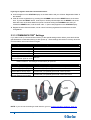
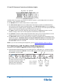
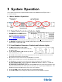
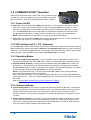
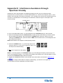
Clear-Com HME DX210 Dual-Channel Wireless Intercom Operating Instructions HME# 400G661 Rev B 6/2/11 Copyright © 2011 Clear-Com, LLC, an HM Electronics, Inc. company. All rights reserved. Clear-Com, the Clear-Com logo and Clear-Com Concert are trademarks or registered trademarks of HM Electronics, Inc. The product described in this document is distributed under licenses restricting its use, copying, distribution, and decompilation/reverse engineering. No part of this document may be reproduced in any form by any means without prior written authorization of Clear-Com, an HME Company. Clear-Com Offices are located in California, USA; Cambridge, UK; Montreal, Canada; and Beijing, China. Addresses and contact information can be found on Clear-Com’s corporate website at www.clearcom.com. Clear-Com Contacts Americas and Asia-Pacific Headquarters California, United States Tel: +1.510.337.6600 Email: [email protected] Europe, Middle East, and Africa Headquarters Cambridge, United Kingdom Tel: +44 1223 815000 Email: [email protected] Canada Office Quebec , Canada Tel: +1 (450) 653-9669 China Office Beijing Representative Office Beijing, P.R.China Tel: (008610)-8528-8748 Clear-Com HME DX210 System Guide FCC NOTICE This device complies with Part 15 of the FCC rules. Operation is subject to the following two conditions :(1) This device may not cause harmful interference, and (2) This device must accept any interference received, including interference that may cause undesired operation. NOTE: This equipment has been tested and found to comply with the limits for a Class A digital device, pursuant to Part 15 of the FCC rules. These limits are designed to provide reasonable protection against harmful interference when the equipment is operated in a commercial environment. This equipment generates, uses and can radiate radio frequency energy and, if not installed and used in accordance with the instruction manual, may cause harmful interference to radio communication. Operation of this equipment in a residential area is likely to cause harmful interference, in which case the user will be required to correct the interference at his own expense. Changes or modifications not expressly approved by Clear-Com, LLC, an HM Electronics, Inc. company could void the user’s authority to operate this equipment. MANDATORY SAFETY INSTRUCTIONS FOR INSTALLERS AND USERS Use only manufacturer or dealer supplied antennas. The Federal Communications Commission has adopted a safety standard for human exposure to RF (Radio frequency) energy, which is below the OSHA (Occupational Safety and Health Act) limits. The term “IC:” before the certification/registration number only signifies that the Industry Canada technical specifications were met. Base Station Antenna minimum safe distance: 7.9 inches (20 cm) at 100% duty cycle. Base Station Antenna gain: This device has been designed to operate with an antenna having a maximum gain of up to 7dBi. Antenna mounting: The antenna(s) used for the base transmitter must be installed to provide a separation distance of at least 7.9 inches (20 cm) from all persons and must not be co-located or operating in conjunction with any other antenna or transmitter. Antenna substitution: Do not substitute any antenna for the one supplied by the manufacturer. You may be exposing person or persons to excess radio frequency radiation. You may contact your dealer or the manufacturer for further instructions. WARNING: Maintain a separation distance from the base station transmit antenna to a person(s) of at least 7.9 inches (20 cm) at 100% duty cycle. WARNING: Excessive sound pressure level from earphones or headphones can cause hearing loss. You, as the qualified end-user of this radio device must control the exposure conditions of bystanders to ensure the minimum separation distance (above) is maintained between the antenna and nearby persons for satisfying exposure compliance. The operation of this transmitter must satisfy the requirements of Occupational /Controlled Exposure Environment, for work-related use. Transmit only when person(s) are at least the minimum distance from the properly installed, externally mounted antenna. Korea: 해당 무선설비는 전파혼신 가능성이 있으므로 인명안전과 관련된 서비스는 할 수 없음 Clear-Com HME DX210 System Guide Hereby, Clear-Com, LLC, an HM Electronics, Inc, company, declares that the DX210 is in compliance with the essential requirements and other relevant provisions of R&TTE Directive 1999/5/EC. This product operates in the 2400 to 2483.5 MHz frequency range. The use of this frequency range is not yet harmonized between all countries. Some countries may restrict the use of a portion of this band or impose other restriction relating to power level or use. You should contact your Spectrum authority to determine possible restrictions. WASTE ELECTRICAL AND ELECTRONIC EQUIPMENT (WEEE) The European Union (EU) WEEE Directive (2002/96/EC) places an obligation on producers (manufacturers, distributors and/or retailers) to take-back electronic products at the end of their useful life. The WEEE Directive covers most Clear-Com products being sold into the EU as of August 13, 2005. Manufacturers, distributors and retailers are obliged to finance the costs of recovery from municipal collection points, reuse, and recycling of specified percentages per the WEEE requirements. Instructions for Disposal of WEEE by Users in the European Union The symbol shown below is on the product or on its packaging which indicates that this product was put on the market after August 13, 2005 and must not be disposed of with other waste. Instead, it is the user’s responsibility to dispose of the user’s waste equipment by handing it over to a designated collection point for the recycling of WEEE. The separate collection and recycling of waste equipment at the time of disposal will help to conserve natural resources and ensure that it is recycled in a manner that protects human health and the environment. For more information about where you can drop off your waste equipment for recycling, please contact your local authority, your household waste disposal service or the seller from whom you purchased the product. Clear-Com, LLC, an HM Electronics, Inc. company, is not responsible for equipment malfunctions due to erroneous translation of its publications from their original English version. Illustrations in this publication are approximate representations of the actual equipment, and may not be exactly as the equipment appears. Clear-Com HME DX210 System Guide Contents 1 System Overview .......................................................................................................................... 1 1.1 1.2 1.3 1.4 1.5 2 System Setup ................................................................................................................................ 4 2.1 2.1.1 2.1.2 2.2 2.3 2.3.1 2.3.2 2.3.3 2.4 2.5 2.6 3 System Components............................................................................................................................ 1 Base Station Front Panel ..................................................................................................................... 2 Base Station Rear Panel...................................................................................................................... 2 Belt Pack – BP210 ............................................................................................................................... 3 All-In-One Headset – WH210............................................................................................................... 3 Battery Charging .................................................................................................................................. 4 Connect AC Power Supply.............................................................................................................. 4 Charge Batteries ............................................................................................................................. 5 Basic Base Station Setup..................................................................................................................... 6 COMMUNICATOR® Setup and Registration........................................................................................ 7 Set Up COMMUNICATOR®s........................................................................................................... 7 Register COMMUNICATOR®s ........................................................................................................ 8 COMMUNICATOR® Settings........................................................................................................... 9 Interfacing with 2-Wire or 4-Wire Intercoms ....................................................................................... 10 Interfacing with Auxiliary Audio Equipment ........................................................................................ 11 ISO Relay........................................................................................................................................... 12 System Operation .......................................................................................................................13 3.1 3.1.1 3.1.2 3.2 3.2.1 3.2.2 3.2.3 3.2.4 3.2.5 3.2.6 3.2.7 3.2.8 Base Station Operation ...................................................................................................................... 13 Digital Radio Controls and Indicator Lights ................................................................................... 13 Local Headset Connector, Controls and Indicator Lights .............................................................. 13 COMMUNICATOR® Operation........................................................................................................... 14 Power On/Off ................................................................................................................................ 14 ISO (Isolate) and IC1, IC2 (Intercom)........................................................................................... 14 Operating Modes........................................................................................................................... 14 Volume Up/Down .......................................................................................................................... 14 Adjusting Microphone Gain ........................................................................................................... 15 Adjusting BP210 Belt Pack Side Tone .......................................................................................... 15 Using WH210 All-In-One Headset Lights-Off Mode ...................................................................... 15 Changing COMMUNICATOR® Batteries ....................................................................................... 15 4 Troubleshooting..........................................................................................................................16 5 Technical Data.............................................................................................................................17 5.1 5.2 5.3 BS210 Base Station Specifications .................................................................................................... 17 BP210 Belt Pack Specifications ......................................................................................................... 18 WH210 All-In-One Headset Specifications......................................................................................... 19 Appendix A: COMMUNICATOR® Indicator Light Functions........................................................20 Appendix B: Multiple Base Station Daisy-Chaining ....................................................................21 Appendix C: Jumper Settings ........................................................................................................22 Appendix D: Multiple Base Station Registration..........................................................................23 Appendix E: Interference Avoidance through Spectrum Friendly.............................................25 Appendix F: Audio Routing Diagram............................................................................................27 Clear-Com HME DX210 System Guide 1 System Overview The Clear-Com® HME DX210 is a 2-channel Digital Wireless Intercom System that supports up to 15 COMMUNICATOR®s per base station, either Belt Packs or All-In-One Headsets, or a combination of the two. Using the DX210 in the 2-channel mode, any 3 of the 15 Communicators can transmit at the same time. In the single-channel mode, any 4 Communicators can transmit at the same time. This number can be increased by adding up to 3 additional base stations. The DX210 supports both Clear-Com and RTS cabled 2-wire intercom systems, and also has 4-wire and auxiliary audio connections. The DX210 operates in the 2.4GHz band, and has provisions for “Spectrum Friendly” co-existence with other devices in the same band. 1.1 System Components BS210 Base Station: Antennas: 110/240 Switching Power Supply: BP210 Belt Pack: WH210 All-In-One Headset: Headset: and/or Belt Pack Pouch: Batteries: 1 Battery Charger with 110/240 Switching Power Supply: Clear-Com HME DX210 System Guide 1.2 Base Station Front Panel 1 2 3 4 5 6 7 8 9 10 11 12 13 14 15 24 25 26 27 28 29 30 16 17 18 19 20 21 22 23 19. 20. 21. 22. 23. DIGITAL RADIO CONTROLS 1. 2. 3. 4. 5. 6. 7. POWER switch RESET button (recessed) CLR/BND button STATUS display REG (registration) button UNLATCH button RECEIVE indicator lights IC2 2-W/4-W SELECT button IC2 AUTO NULL button (recessed) IC2 4-W output level adjust IC2 4-W input level adjust IC2 4-W indicator light AUXILIARY CONTROLS 24. 25. 26. 27. 28. 29. 30. IC1 CONTROLS 8. 9. 10. 11. 12. 13. 14. 15. 31 32 33 34 35 36 37 IC1 2-W output level adjust IC1 2-W input level adjust IC1 2-W indicator light IC1 AUTO NULL button (recessed) IC1 2-W/4-W SELECT button IC1 4-W indicator light IC1 4-W input level adjust IC1 4-W output level adjust AUX IC1/IC2 INPUT ASSIGN indicators AUX INPUT ASSIGN button AUX INPUT level adjust AUX IN indicator light AUX INPUT/OUTPUT SELECT button AUX OUT indicator light AUX OUTPUT level adjust HEADSET CONTROLS 31. 32. 33. 34. 35. 36. 37. IC2 CONTROLS 16. IC2 2-W indicator light 17. IC2 2-W input level adjust 18. IC2 2-W output level adjust HEADSET IC1, IC2 & ISO indicator lights HEADSET IC1, IC2 & ISO SELECT button HEADSET VOLUME knob HEADSET TALK indicator light HEADSET TALK On/Off button HEADSET MIC LEVEL adjust HEADSET cable connector 1.3 Base Station Rear Panel 38 38. 39. 40. 41. 42. 43. 44. 45. 2 39 40 41 42 43 44 ANT (R-TNC) PRIMARY/SECONDARY Select Switch IC1 4-W RJ-45 Connector IC1 2-W XLR-3M Connector IC1 2-W XLR-3F Connector CLEAR-COM/RTS Select Switch IC2 2-W XLR-3F Connector IC2 2-W XLR-3M Connector Clear-Com HME DX210 System Guide 45 46 46. 47. 48. 49. 50. 51. 52. 53. 47 48 49 50 51 52 53 IC2 4-W RJ-45 Connector SINGLE/DUAL Channel Select Switch AUX IN Connector AUX OUT Connector Relay Connector DC Power Connector ANT (R-TNC) Chassis Grounding Screw 1.4 Belt Pack – BP210 3 4 5 2 6 1 7 9 8 1. 2. 3. 4. 5. Headset cable connector Power/mode lights IC2 (Intercom 2) button ISO (Isolate) button IC1 (Intercom 1) button 10 6. 7. 8. 9. 10. PWR (Power) button Volume-up button Volume-down button Battery Battery-release latch 1.5 All-In-One Headset – WH210 3 4 5 2 6 1 9 1. 2. 3. 3 Battery Battery-release latch Power button Clear-Com HME DX210 System Guide 4. 5. 6. 7. 8. 9. Power/mode lights IC1 (Intercom 1) button IC2 (Intercom 2) button Volume-up button Volume-down button ISO (Isolate) button 7 8 2 System Setup This chapter describes how to set up and configure the DX210. Typical equipment connections to the rear panel of the base station 2.1 Battery Charging Before installing the system, connect the AC power supply to the battery charger and plug it into an electrical outlet. Charge all the batteries while the other equipment is being installed. Charging time is about 2.5 hours. 2.1.1 Connect AC Power Supply To connect the AC power supply to the battery charger: ● Connect the AC power supply cable connector to the power connection on the battery charger and turn clockwise to lock in place. ● Connect the AC power cord connector to the AC power supply unit. ● Connect the AC power cord to an electrical outlet. Power supply cable connector Battery Charger AC power supply Power cord connector To electrical outlet Power cord The red lights on the charger will come on briefly, and then the yellow lights will come on and stay on. 4 Clear-Com HME DX210 System Guide 2.1.2 Charge Batteries Up to four batteries can be charged in the battery charger at the same time. The battery status lights next to each charging port are explained below. Up to six fully charged batteries can be stored in the battery storage ports. ● Insert a battery in each of four charging ports until it clicks in place. ● A yellow light next to each charging port stays on while the port is empty. When a battery is in a charging port, a flashing yellow light next to it indicates CHARGE PENDING, which means the battery is too hot. Adjust the room temperature or move the charger to a cooler area. When a battery is in a charging port, a yellow light on steady next to it means CHARGE FAILED. If this happens, follow the instructions on the side of battery charger. ● A red CHARGING light next to a battery port stays on while a battery in the port is charging. ● A green READY light next to a battery port goes on when a battery in the port is fully charged. ● Store fully charged batteries in storage ports. NOTE: Batteries should not be left in charge ports after being fully charged. If a battery is left in a charge port for more than three weeks, the yellow indicator may light up. In this case, it does not indicate a faulty battery. 5 Clear-Com HME DX210 System Guide 2.2 Basic Base Station Setup This section describes setup and equipment connections for an individual base station. ● Connect the two enclosed antennas to the antenna connectors (#38 and #52) on the rear panel of the base station, and turn the sleeves clockwise on the antenna connectors to tighten them securely in place. Position the antennas at 90° angles from each other. 90o 38 47 51 52 Base station rear panel AC power supply AC power cord ● Plug the connector at the end of the AC power supply cord into the +12-14VDC power connector (#51) on the rear panel of the base station. Turn the locking nut on the cable connector clockwise to secure it to the base station. Plug the female connector at one end of the AC power cord into the power supply. Plug the other end of the AC power cord into an electrical outlet. ● Set switch #47 for the base station to operate in single or dual channel mode. In single channel mode, all wireless users will be able to hear each other. Up to four users can talk simultaneously. In dual channel mode, there are two separate audio channels enabling two groups of users to independently communicate with each other. Up to three users can talk simultaneously. NOTE: Any time the mode is changed, the unit must be reset using the reset button or by power cycling for the change to take effect. 1 Base station front panel 37 ● If a local headset will be used, plug it into the HEADSET connector (#37) on the front panel of the base station. NOTE: The connector is keyed, so the headset cable plug can not be inserted in the wrong direction. ● Press the POWER switch (#1) on the front panel to turn on the base station. A red light on the switch should go on. If you have more than one base station, refer to Appendix D, page 23 for multiple base station registration. 6 Clear-Com HME DX210 System Guide 2.3 COMMUNICATOR® Setup and Registration The first time you operate the DX210 system, you must register each Communicator (Belt Pack and/or All-In-One Headset) for use with a specific base station. The base station will then recognize all registered Communicators when their power is on, and will know the difference between them and other electronic equipment operating on the same frequencies. If a Communicator is added or replaced later, the new one must be registered and the old one remains in memory. A maximum of 15 Communicators can be registered to a single base station at one time. 2.3.1 Set Up COMMUNICATOR®s NOTE: If multiple base stations will be used, or if interference is present, such as Wi-Fi interference, refer to Base Station Registration and Interference Avoidance, in Appendix D and E, pages 23 and 25. Before registering them, set up all Communicators as follows: Belt Packs Power button ● 1 - Insert a fully charged battery in each Belt Pack, with the metal contacts on the end of the battery inserted first. Press it in until it snaps. 1 3 2 ● 2 - Place each Belt Pack in a pouch. ● 3 - Plug its headset cable connector into each Belt Pack. All-In-One Headsets Insert a fully charged battery in each Headset, with the metal contacts on the end of the battery inserted first. Press it in until it snaps. 7 Clear-Com HME DX210 System Guide Power button 2.3.2 Register COMMUNICATOR®s The Communicator must be within 6 feet (1.83 meters) of the base station to enable registration. 1. Be sure each Communicator you are going to register is turned off and the base station power is on before you begin. Communicators that are already registered can be on or off. 2. Put the headset on your head. 3. Press the REG button on the front panel of the base station. The STATUS display will show a small “o” for open. STATUS display “o” REG button NOTE: If you wait too long before going on to the next step, the base station will go out of the registration mode and you will have to press the REG button again. Press and hold the ISO button on the Communicator while you press and release the PWR (power) button to turn the unit on, then release the ISO button. This will cause the Communicator to enter the registration mode. 4. On Belt Packs, the two power lights at the corners near the IC1 and IC2 buttons will begin blinking red, then will blink green two or three times and go off. Wait! There may be a short delay. On All-In-One Headsets, the power/mode lights at the end of the microphone boom and on the side of the unit near the IC1 button will blink. Wait! There may be a short delay. If registration is successfully completed: ● A voice message in the headset will say “Power on, Belt Pack #, Version #, Begin registration, Registration complete, …” ● After a delay of about 15 seconds, the STATUS display will show the ID number assigned to this Communicator for about 10 seconds. NOTE: ID numbers are assigned sequentially as 0 thru 9, A, b, C, d and E. ● The power light on the Communicator will remain on steady green. Repeat Steps 2 to 4 above for each Communicator to be registered. If registration failed: ● A voice message in the headset will say “Power on, Belt Pack #, Version #, Begin registration, …” Both lights on the Belt Pack will be blinking red, and there may be a delay of up to 90 seconds before you hear “Registration failed.” ● Press the RESET button at the lower-left corner of the base station with a pen or similar pointed object. When the STATUS display becomes blank, press the REG button and register the Communicator again. If registration fails again, call your dealer for assistance. 8 Clear-Com HME DX210 System Guide If you try to register more than 15 Communicators: ● An F will appear on the STATUS display on the base station and you will hear “Registration failed” in the headset. ● Clear all current registrations by pressing the CLR/BND button and the RESET button at the same time. To press the RESET button, insert a pen or similar pointed object into the RESET hole at the lower-left corner of the base station front panel. Continue holding the CLR/BND button after you release the RESET button, until the clear code “c” (lower case) appears on the STATUS display. ● Register all active Communicators, one at a time. Previously registered Communicators must be re-registered. 2.3.3 COMMUNICATOR® Settings If you want to set up a Communicator with any of the special settings shown below, press and hold the specified button combinations during or after power up. These settings will remain in memory when the Communicators are turned off and on again. For Setting Press & Hold while you Press & Release the Power button IC1 button ISO restrict on IC1 and ISO buttons ISO restrict off IC1 and/or IC2 and/or ISO and ▲ volume up buttons Handsfree on selected button(s) IC1 and/or IC2 and/or ISO and ▼ volume down buttons Handsfree off selected button(s) Listen-Only mode on ▼ volume down button Listen-Only mode off ▲ volume up button WH210 only * IC2 button All-In-One Headset “lights-off” mode * NOTE: All-In-One Headsets can be set up with its indicator lights off, to avoid distraction if users are in an area visible to audience. This setting is not saved when you power off. For Setting With the power already on - - - Press IC2 while you repeatedly press the ▲ volume up button Increase mic gain (15 steps) Press IC2 while you repeatedly press the ▼ volume down button Decrease mic gain (15 steps) BP210 only * Press IC1 while you repeatedly press the ▲ volume up button Increase sidetone level (5 steps) BP210 only * Press IC1 while you repeatedly press the ▼ volume down button Decrease sidetone level (5 steps) * NOTE: There is no sidetone adjustment function for All-In-One Headsets. Power button NOTE: If you are not connecting a wired intercom, go on to System Operation, section 3, page 13. 9 Clear-Com HME DX210 System Guide 2.4 Interfacing with 2-Wire or 4-Wire Intercoms 40 41 42 43 Base station rear panel 2-Wire Intercom Interface: The following 2-wire setup is for Channel 1 (IC1). If applicable, repeat for Channel 2 (IC2). ● If using a 2-wire intercom with the DX210, plug it into the base station 2-W connector at #41 or #42, depending on whether a male or female connection is required. ● Depending on whether you are using a Clear-Com® or RTS® compatible 2-wire intercom system, position the CLEAR-COM / RTS button (#43) as follows: In position = RTS Mode Out position = Clear-Com Mode ● Press the IC1 SELECT button (#12) on the front panel of the base station. The 2-W light (#10) next to the button should turn green. NOTE: If no power is detected at the 2-W connector, the 2-W light will come on red and no audio will be passed through. Plugging in a connection to a Clear-Com or RTS power supply, at this point, will turn the light green and operation will begin. ● Be sure there are no open microphones on the wired intercom. If users are wearing headsets, please notify them of the impending audio sweep prior to auto nulling. Press and hold the AUTO NULL button for two seconds. To press the AUTO NULL button, insert a pen or similar pointed object into the AUTO NULL hole on the front panel of the base station. An audio sweep will be heard for 25 seconds on the wired Belt Packs. (The 2-W light (#10) next to the button should turn amber, then green.) ● Adjust the 2-W intercom receive and send levels with the IC1 2-W INPUT control (#9) and OUTPUT control (#8). NOTE: If you are not connecting other equipment, go on to System Operation, section 3, page 13. 4-Wire Intercom Interface: The following 4-wire setup is for Channel 1 (IC1). Repeat for Channel 2 (IC2) if applicable. ● If using a 4-wire intercom with the DX210, plug it into the base station IC1 4-W connector (#40). ● Press the respective SELECT button until the IC1 4-W light (#13) next to the button goes on. ● Adjust the 4-wire intercom receive and send levels with the IC1 4-W INPUT and OUTPUT (#14 & 15) controls. RJ45 Connector Pins Pins 1, 2, 7 and 8 Pin 3 Pin 4 Pin 5 Pin 6 Designation N/C (reserved) Intercom Out + Intercom In + Intercom In – Intercom Out – NOTE: Simultaneous 2-wire and 4-wire communication is possible. Both groups of intercom users can communicate with the base station operator, but not with each other. 10 Clear-Com HME DX210 System Guide IC1 and IC2 Intercom Controls and Indicator Lights: 8 9 10 11 12 13 14 15 Base station front panel The IC1 portion of this area of the panel is for Intercom Channel 1, and the IC2 portion is for Intercom Channel 2. Their operation is identical. ● The SELECT button is used to select 2-Wire or 4-Wire or both. ● The 2-W indicator light will come on red (muted) if wired intercom power is not detected at the 2-W connector on the rear panel of the base station. The 2-W indicator light will come on green if 2-W equipment which supplies power is plugged into the 2-W connector on the rear panel of the base station, or if the respective bypass jumper inside the unit has been set. ● The INPUT controls are used to adjust the audio levels going to COMMUNICATOR®s or a local headset, coming in from 2-W and 4-W equipment connected to the base station. ● The OUTPUT controls are used to adjust the audio levels coming in from Communicators or a local headset, as it goes out to 2-W and 4-W equipment connected to the base station. ● The AUTO NULL button is used to eliminate echo caused by mismatched line characteristics of an external 2-W system. CAUTION: Before pressing the AUTO NULL button, be sure there are no open microphones on the wired system. Use a pen or similar pointed object to press and hold the AUTO NULL button for 2 seconds. NOTE: If you are not connecting other equipment, go on to System Operation, section 3, page 13. 2.5 Interfacing with Auxiliary Audio Equipment ISO Audio can be routed to the AUX OUT connector for page or stage announce. ● If using auxiliary audio equipment such as another intercom, a CD player, etc., connect its output cable connector (male) to the AUX IN connector (#48), and/or its input cable connector (female) to the AUX OUT connector (#49). 48 49 Base station rear panel The cable connectors must be 3-pin XLR type for balanced +20dBu maximum audio input/output, with the following pin connections: 11 Clear-Com HME DX210 System Guide Pin 1 = Ground Pin 2 = Audio + Pin 3 = Audio – The AUXILIARY SELECT button (#25) is used to select IC1 or IC2 or both as the destination for AUX IN audio. The IC1 and/or IC2 INPUT ASSIGN lights (#24) come on green to indicate the selection as the destination for AUX IN audio. If neither is selected, AUX IN audio will not be routed to the COMMUNICATOR®s. The AUX IN light must be lit for the INPUT ASSIGN SELECT function to work. ● If only AUX IN is used, press the AUX IN/OUT SELECT 25 button (#28) until the IN light (#27) goes on. Listen to the audio input in your headset as you adjust the INPUT control (#26) below the light to the desired level. 26 27 28 29 30 24 ● If only AUX OUT is used, press the AUX IN/OUT SELECT button (#28) until the OUT light (#29) comes on. Check the audio level on the auxiliary equipment, and adjust the OUTPUT control (#30) to the desired level. Base station front panel ● If the auxiliary equipment requires two-way communication, have someone listening at the auxiliary unit. Press the AUX IN/OUT SELECT button (#28) until both the IN and OUT lights (#s 27 and 29) go on. While speaking into your headset microphone, adjust the OUT control (#30) above the light to the desired listening level at the auxiliary unit. Listen to the audio input in your headset as you adjust the INPUT control (#26) below the light to the desired level. Auxiliary Controls and Indicator Lights: ● The SELECT button on the right (#28) is used to select AUX IN (audio from auxiliary equipment connected to the base station), AUX OUT (audio to the auxiliary equipment from the ISO channel of the COMMUNICATOR®s and local headset) or both. ● The IN and OUT lights come on green to indicate the selection. ● The INPUT and OUTPUT controls adjust auxiliary inbound and outbound audio levels. ● The SELECT button on the left (#25) is used to select IC1 or IC2 or both as the destination for AUX IN audio. The IC1 and/or IC2 INPUT ASSIGN lights come on green to indicate the selection as the destination for AUX IN audio. NOTE: If you are not connecting other equipment, go on to System Operation, section 3, page 13. 2.6 ISO Relay During ISO communication, a relay closure is provided. This can be used for tasks such as keying a long range radio or triggering an alert light. It can be activated from a Communicator or a local headset. 50 Base station rear panel 12 Clear-Com HME DX210 System Guide 3 System Operation This chapter describes how to operate the Base Station and COMMUNICATOR® (Belt Pack or All-In-One Headset). 3.1 Base Station Operation COMMUNICATOR® Registration Power Switch AUX IN Assign and AUX In/Out Controls Audio Channel and Auto-Null Controls Local Headset Connnector & Controls 3.1.1 Digital Radio Controls and Indicator Lights ● The CLR/BND button, RESET button, STATUS indicator and REG button are used when registering Communicators. Refer to Communicator registration procedure, page 8. ● The UNLATCH button is used by the base station operator to unlatch all Communicator transmitters. ● The RECEIVE IC1, IC2 (Intercoms) and ISO (Isolate) lights indicate whether reception from a Communicator is on IC1, IC2 or ISO. 3.1.2 Local Headset Connector, Controls and Indicator Lights ● The SEL (select) button is used to select communication from the local headset to IC1, IC2, IC1 & IC2, or ISO. ● The IC1, IC2, IC1 & IC2, or ISO indicator light will be lit for the selection you made. ● IC1 and IC2 communication will be heard by wireless users on the respective channel, as well as users wired into 2-W and 4-W connections. ● ISO is heard in both wireless channels, and AUX OUT if activated. NOTE: When the ISO button is pressed, ISO RELAY (#50) is activated. ● The TALK button is used for communication from the local headset to the selected channel. For open communication, press and release the TALK button quickly to “latch on.” To “latch off,” press and release the button again quickly. For momentary communication, press and hold the TALK button for more than one second. In this mode, the selected channel will remain open only as long as you are pressing the TALK button. The TALK light indicates the TALK mode is active via the local headset. ● Use the VOLUME control to adjust the output to the local headset earpiece. ● Use the MIC LEVEL control to adjust the audio level from the local headset microphone. 13 Clear-Com HME DX210 System Guide 3.2 COMMUNICATOR® Operation Belt Pack control buttons have a snap action. They will activate when pressed firmly. Use your fingertips, not your fingernails, to press the Belt Pack buttons. All-In-One Headset buttons are touch sensitive. 3.2.1 Power On/Off ● Power On – Press and release the PWR (power) button. A voice message in the earpiece will say “power on,” and the red power lights near the corners of the IC1 and IC2 buttons will go on. After a short time, one light will go off and the other will change to green, indicating the Belt Pack is ready for use. The STATUS indicator on the base station will momentarily indicate the ID of the Belt Pack. The green power light will be on steady whenever the Belt Pack is ready, but not transmitting. NOTE: While the Belt Pack is transmitting, the green power light will be flashing. ● Power Off – Press and hold the PWR button for approximately two seconds. A voice message in the earpiece will say “power off,” and the green power light will go off. 3.2.2 ISO (Isolate) and IC1, IC2 (Intercom) Use the ISO button to talk to other wireless Communicator users and the base station operator. Pressing ISO on the Belt Pack will also send audio to AUX OUT if the AUXILIARY OUT light on the front of the base station is on. Use the IC1 and IC2 buttons to communicate via the wired intercom channels and the base station operator. When the ISO button is pressed, ISO RELAY (#50) is activated. 3.2.3 Operating Modes ● Push-To-Talk ONLY Mode Operation – In PTT operation, audio is transmitted only while you are pressing and holding the IC1, IC2 or ISO button. When you release the button, transmission stops. ● Hands-free Mode Operation – Quickly press and release the IC1, IC2 or ISO button to “latch” the transmitter on. Talk and listen, as in a normal telephone conversation. Quickly press and release the same button again to “unlatch,” and end the conversation. The base station operator can unlatch all Communicators by pressing the UNLATCH button on the base station. NOTE: In the hands-free mode, if you are latched in IC1, IC2 or ISO, quickly pressing/releasing either of the other buttons will latch on that button. Also in the hands-free mode, if you are latched in IC1 or IC2 and then press and hold the ISO button, it will function as PTT. When you release the ISO button, the Communicator will revert to the latched IC1 or IC2. Refer to Communicator indicator light functions, Appendix A, page 20. 3.2.4 Volume Up/Down ● Volume Up Adjustment – Each time you press and release the volume-up ▲ button, a beep will be heard in the earpiece as the volume increases one step. If you press and hold the volume-up button, repeating beeps will be heard as the volume steps up to maximum. When maximum volume is reached, “maximum “will be heard in the earpiece, and will be repeated until you release the volumeup button. ● Volume Down Adjustment – Each time you press and release the volume-down ▼ button, a beep will be heard in the earpiece as the volume decreases one step. If you press and hold the volumedown button, repeating beeps will be heard as the volume steps down to minimum. When minimum volume is reached, rapidly repeating beeps will be heard. 14 Clear-Com HME DX210 System Guide 3.2.5 Adjusting Microphone Gain Some users talk louder/softer than others. To allow for this, microphone gain adjustment is provided. ● To increase microphone gain – While holding down the IC2 button, press the volume-up ▲ button as many times as necessary to reach the desired level. The microphone gain increase can be monitored through side tone, or preferably by someone else using a Communicator or at the base station. ● To decrease microphone gain – While holding down the IC2 button, press the volume-down ▼ button as many times as necessary to reach the desired level. The microphone gain decrease can be monitored through side tone, or preferably by someone else using a Communicator or at the base station. NOTE: The mic gain setting will be indicated, in number format, by a voice prompt (typically, HS14 = 5, HS15 = 3, HS16 = 3). You will hear “Maximum” if you attempt to go higher than maximum mic gain. You will hear repeating beeps if you attempt to go lower than minimum mic gain. Microphone gain will be saved in memory and does not require readjustment each time the power is turned on. (Default setting is 3.) 3.2.6 Adjusting BP210 Belt Pack Side Tone ● To increase side tone – Press the volume-up ▲ button while holding down the IC1 button in the normal operating mode. ● To decrease side tone – Press the volume-down ▼ button while holding down the IC1 button in the normal operating mode. NOTE: The side tone setting will be indicated in numbers, by a voice prompt. (Default setting is “Max.”) 3.2.7 Using WH210 All-In-One Headset Lights-Off Mode The Lights-Off mode can be used to avoid audience distraction from the lights on the All-In-One Headsets. ● To operate in the Lights-Off mode, with the WH210 power off, press and hold the IC2 button while you press the POWER button, and then release both buttons. ● To get out of the Lights-Off mode, power the WH210 off and back on again without pressing the IC2 button. NOTE: There is no sidetone adjustment number for the All-In-One Headset. 3.2.8 Changing COMMUNICATOR® Batteries When a Communicator battery becomes weak, a voice in the earpiece will say “Change battery.” If using a Belt Pack, you must remove it from its pouch to access its battery. Battery Battery-release latch Belt Pack battery removal Battery-release latch Battery All-In-One Headset battery removal Slide the arrow-shaped battery release latch in the direction of the arrow. Pull up on the battery near the battery-release latch and lift the battery out of the unit, or turn the unit over and catch the battery in your hand. When replacing a battery, place the end of the battery with the metal contacts into the battery holder, in the same position as the battery you removed. Press the top of the battery carefully into the battery holder until it snaps in place under the battery-release latch. 15 Clear-Com HME DX210 System Guide 4 Troubleshooting ● Red light on base station power switch does not come on. Be sure the power cords are properly connected to base station, power supply and electrical outlet. ● Belt Pack power lights do not turn green and “out of range” is heard in the headset. Be sure your base station power is on. Turn the Belt Pack and base station power on and off. You may be too far from the base station. The range varies with each location’s layout. ● When trying to register, it keeps saying registration failed. Refer to “If registration failed” in section 2.3.2, page 8, and repeat the registration procedure. If “F ” shows up on the STATUS display, it indicates that an attempt has been made to register more than 15 Belt Packs. Follow the related instructions in section 2.3.2, page 9. ● Others cannot hear me when I talk. Be sure the headset is securely connected to the Belt Pack or base station, and that you are pressing the IC1, IC2 or ISO button on the Belt Pack, or the TALK button on the base station. Be sure the appropriate IC1, IC2 or ISO setting is selected in the HEADSET section of the base station front panel. ● People on the 4-wire intercom cannot hear me or I cannot hear them. Be sure the cables are securely connected and the 4-wire intercom is on. If using a local headset, be sure the desired IC setting is selected in the HEADSET section of the base station front panel. If using a Belt Pack or All-In-One Headset, press the desired IC button. ● People on the RTS®/Clear-Com® systems cannot hear me, or I cannot hear them. Be sure the cables are securely connected and the 2-wire intercom is on. If using the local headset, be sure the desired IC setting is selected in the HEADSET section of the base station front panel. If using a Belt Pack or All-In-One Headset, press the desired IC button. ● The 2-wire intercom is on and there is a loud squeal whenever I try to talk. This can occur if two or more base stations are daisy-chained without terminating the appropriate channel. The termination is set by putting JP5 (IC1) and/or JP6 (IC2) in the ON position. This should be done in only one base station. Refer to Appendix C, page 22 for jumper (JP) locations. ● Settings are not retained when the base station power is turned off and on again. The internal battery may be low. Contact your dealer. ● 2-W LEDs remain red. No 2-wire power detected. Plug into 2-W power supply. If the lack of powered 2-W system is intentional (such as when using a Clear-Com MT1, or when daisy-chaining multiple base stations), open the base station cover and set JP1 (IC1) and/or JP2 (IC2) to the ON position. If daisy-chaining, do not forget to also terminate one of the base stations by setting JP5 (IC1) and/or JP6 (IC2) to ON. Refer to Appendix C, page 22 for jumper (JP) locations. ● Echo on 2-W line. Be sure no wired Belt Packs have open mics and that the line is terminated, and rerun Auto Null. 16 Clear-Com HME DX210 System Guide 5 Technical Data 5.1 BS210 Base Station Specifications GENERAL Channels: Frequency Range: Frequency Response: Power Requirements: Temperature Range: Size: Weight: # of COMMUNICATOR®s per Base: 2 audio channels 2400 – 2483.5 MHz 200 Hz to 3.5 kHz 100-240VAC, 50-60Hz or 12-14VDC 32-122°F (0-50°C) 19” x 1.72” x 17.13” (1-RU) (48.26 x 4.37 x 43.51 cm) 9.0 lbs. (4.1 kg) maximum 15 can be registered. In single-channel operation, 4 can have simultaneous full-duplex communication. In dual-channel operation, 3 can have simultaneous full-duplex communication. RJ45, 600Ω balanced, level adjustable, simultaneous operation with 2-wire 4-Wire I/O: XLR-3M, XLR-3F, externally-switchable RTS® or Clear-Com® mode, 2-Wire I/O: 200Ω, level adjustable, null adjustable to 50dB attentuation, typical XLR-3F/¼” (6.35 mm) combo jack, 600Ω balanced, level adjustable Auxiliary Input: XLR-3M, 600Ω balanced, level adjustable Auxiliary Output: 4-pin mini-DIN, Electret microphone Headset Connector: 200mW into 32Ω Headset Output: External ½ -wave dipole (R-TNC connector), RX/TX horizontal/vertical diversity Antenna Type: <2% System Distortion: Communication Security: 64-bit encryption, dual-slot diversity BASE STATION TRANSMITTER Type: Transmit Power: Modulation Type: Frequency Stability: Harmonics/Spurious: Frequency Hopping, Spread Spectrum (FHSS) 100mW burst Gaussian filtered FSK, TDMA 13 ppm Exceeds FCC and ETSI specifications over temperature BASE STATION RECEIVER Type: RF Sensitivity: Frequency Stability: Distortion: 17 Frequency Hopping, Spread Spectrum <-90dBm w 10-3 BER 13 ppm <2% Clear-Com HME DX210 System Guide 5.2 BP210 Belt Pack Specifications GENERAL Channels: Frequency Range: Antenna: Frequency Response: Battery Requirements: Battery Life: Temperature Range: Weight: Headset Connector: Microphone: Headset Output: Controls: Indicators: Communication Security: System Distortion: 2 audio channels 2400 MHz – 2483.5 MHz Internal, horizontal/vertical diversity 200 Hz to 3.5 kHz 3.6V lithium ion Up to 20 hours 32-122°F (0-50°C) 7.4 oz (.21 kg) with battery and pouch 4-pin, mini-DIN Electret 160mW into 32Ω Power, Volume-up, Volume-down, IC1, IC2, ISO Dual-color LED (red/green) 64-bit encryption <2% BELT PACK TRANSMITTER Type: Transmit Power: Transmission Modes: Modulation Type: Frequency Stability: Harmonics/Spurious: Frequency Hopping, Spread Spectrum 100mW burst Momentary or latch Gaussian filtered FSK, TDMA 13 ppm Exceeds FCC and ETSI specifications BELT PACK RECEIVER Type: RF Sensitivity: Frequency Stability: Distortion: 18 Frequency Hopping, Spread Spectrum <-90dBm w 10-3 BER 13 ppm <2% Clear-Com HME DX210 System Guide 5.3 WH210 All-In-One Headset Specifications GENERAL Channels: Frequency Range: Antenna: Frequency Response: Battery Requirements: Battery Life: Temperature Range: Weight: Microphone: Headset Output: Controls: Indicators: Communication Security: System Distortion: 2 audio channels 2400 MHz – 2483.5 MHz Internal 200 Hz to 3.5 kHz 3.6V lithium ion Up to 20 hours 32-122°F (0-50°C) 5.7 oz (.16 kg) with battery Electret 160mW into 32Ω Power, Volume-up, Volume-down, IC1, IC2, ISO Dual-color LED (red/green) 64-bit encryption <2% HEADSET TRANSMITTER Type: Transmit Power: Transmission Modes: Modulation Type: Frequency Stability: Harmonics/Spurious: Frequency Hopping, Spread Spectrum 100mW burst Momentary or latch Gaussian filtered FSK, TDMA 13 ppm Exceeds FCC and ETSI specifications HEADSET RECEIVER Type: RF Sensitivity: Frequency Stability: Distortion: 19 Frequency Hopping, Spread Spectrum <-90dBm w 10-3 BER 13 ppm <2% Clear-Com HME DX210 System Guide Appendix A: COMMUNICATOR® Indicator Light Functions BP210 Belt Pack Indicator Lights: BP210 Condition IC1 Indicator Light IC2 Indicator Light IC1 Idle Steady Green OFF IC1 TX Blinks Green OFF IC2 Idle OFF Steady Green IC2 TX OFF Blinks Green ISO TX Blinks Green Blinks Green Low battery Appropriate channel light Blinks Red when in idle mode WH210 All-In-One Headset Indicator Lights: WH210 Condition Main Indicator Light Boom Indicator Light IC1 Idle Steady Green Off IC1 TX Blinks Green Steady Green IC2 Idle Steady Red Off IC2 TX Blinks Red Steady Green ISO TX Blinks Red or Green (depending on previous Mode) Steady Red Low battery No indication 20 Clear-Com HME DX210 System Guide Appendix B: Multiple Base Station Daisy-Chaining Two or more DX210 base stations can be “daisy-chained” together with cables connected to the 2-W connectors on the rear panels of each base station, following Clear-Com® / RTS® standards, or two base stations (not more) can be “daisy-chained” together with cables connected to the 4-W or AUX connectors. NOTE 1: DX210 does not provide 2-wire line power, therefore, 2-wire power bypass must be used. RTS® Mode Clear-Com® Mode Pin 1 = Common Pin 2 = Channel 1 Pin 3 = Channel 2 Pin 1 = Common Pin 2 = N/C Pin 3 = Audio NOTE 2: For AUX type daisy-chaining, the cable connectors must be 3-pin XLR. ● If using 4-wire connection, use cable with In/Out crossed, as shown to the right. (An Ethernet crossover cable will not work.) IC In + ─── IC Out + IC In – ─── IC Out – IC Out + ─── IC In + IC Out – ─── IC In – ● If using 2-Wire connections, open each base station and set jumpers JP1 (IC1) and/or JP2 (IC2) in all base stations to ON for power detect bypass. Set jumpers JP5 (IC1) and/or JP6 (IC2) in only one base station per channel for termination. Refer to Appendix C, page 22. ● Perform base station registration for each base station. Refer to Appendix D, page 23. 21 Clear-Com HME DX210 System Guide Appendix C: Jumper Settings The base station has internal jumpers that are used to set ISO broadcast restrict, power detect by-pass, and 2-wire channel termination. Jumper # JP1 JP2 JP3 JP4 JP5 JP6 JP7 Function Channel 1, 2-wire power detect bypass Channel 2, 2-wire power detect bypass Reserved Disable ISO from going out to Belt Packs Channel 1, 2-wire termination Channel 2, 2-wire termination Reserved ISO Broadcast Restrict This feature prevents ISO communication from being broadcast from one COMMUNICATOR® to other Communicators. Local headset ISO will still be broadcast, and the local headset will still receive ISO communication. To enable this feature, set JP4 to ON. Power Detect Bypass In the event the DX210 base station is connected to a 2-W line which does not contain power (such as when multiple base stations are daisy chained), JP1 (IC1) and/or JP2 (IC2) need to be set to ON to enable 2-W interface for the respective channel(s) to come on. WARNING! If no termination is present on the line, enabling this feature will cause feedback in the headsets. 2-Wire Channel Termination If termination of the base station is necessary (such as when multiple base stations are daisy chained), set the JP5 (IC1) and/or JP6 (IC2) jumpers to the ON position on one base station, when connecting multiple base station together via 2-wire connection. Only one base station should be terminated per channel. 22 Clear-Com HME DX210 System Guide Appendix D: Multiple Base Station Registration For multiple base stations to operate in close proximity without interference, they must all be properly registered before performing any other setups. After registering each base station, register each COMMUNICATOR® that will be used with that base according instructions in section 2.3.2, page 8. NOTE: If using split-band operation, select the appropriate band prior to base station registration. If a different frequency band needs to be selected to avoid interference, the primary base station must be set to this frequency band before base station registration is started. Register each base station and all Belt Packs and/or All-In-One Headsets as follows: ● On one of the base stations, ensure that the primary/secondary switch is set to primary. On the others, ensure that it is set to secondary. NOTE: In split band operation, there can be one primary and up to three secondary base stations in either band. ● Turn the primary base station power on. Register any Communicators to be used with the primary base station, as instructed in section 2.3.2, page 8. Turn each Communicator off after registering it. ● Power on one secondary base station. The STATUS display will show a double bar, indicating the secondary base station is ready to be registered. Double bar Base station ready to be initialized Small “o” Small "o" indicates primary base station is open for registration ● Press the REG (register) button on the primary base station. The STATUS display will show a small “o.” ● To assign a number to a secondary base station and register it, press the REG button on the secondary base station. Pressing the button repeatedly causes it to cycle through the numbers 1, 2, and 3. When the desired number appears, stop pressing and wait. While the secondary base station is registered using the displayed number, the STATUS display will continue showing the secondary number selected. When registration of the secondary base station is finished, the display will show one bar, to indicate the secondary has been registered to the primary. Secondary base number Secondary 2 searching for primary One bar Secondary is initialized to primary ● Press the REG button on the primary. The STATUS display will go blank. ● Register Communicators to the secondary base stations as instructed in section 2.3.2, page 8. After registration, turn off the secondary base station and all Communicators. 23 Clear-Com HME DX210 System Guide ● Repeat these steps for each remaining secondary base station. Use a different number for each. Only the primary base station and the secondary base station you are currently working with should have power on during registration. All other equipment should be off. ● After all secondary base stations are registered and COMMUNICATOR®s are registered, power up all base stations. Press reset on the primary base station and let it recover. Turn on the primary Communicators and let them link. Press the reset on each secondary base station one at a time and let it link to the primary, as indicated by a single bar. Turn on the Communicators associated with the secondary base stations. Do one group at a time until they have all linked. Then do the next group. At this point all base stations and Communicators should be powered up and linked, ready for use. ● Now proceed with normal system configuration, setting functions and levels as required. ● If it becomes necessary to replace a secondary base station, use the procedure above to register the new secondary with the same number as the old secondary. After registration, you will have to register any Communicators associated with the old secondary to the new secondary base station. ● If it becomes necessary to replace a primary base station, follow the above procedure completely. Before registration of the secondary base stations, clear the previous secondary registration as follows. For each secondary, press the CLR/BND button and the RESET button at the same time. Continue holding the CLR/BND button after you release the RESET button, until the clear code “c” (lower case) appears on the STATUS display. Any Communicators associated with the old primary will have to be registered to the new primary after secondary base station registration. All Communicators associated with secondary base stations also have to be registered again. ● If the primary base station is shut down or if the primary base is powered off for more than 30 seconds, all secondary base stations will drop their Communicator connections and begin searching for the primary. If the primary is not found in 30 seconds, the secondary will automatically revert to primarymode operation and reconnect the Communicators. At this point the secondary STATUS displays will show three bars. If the primary is turned back on it will be necessary to press RESET on all secondary base stations to allow them to find and initialize to the primary again. It is therefore important to have all base stations connected to the same AC circuit to prevent this situation when the system is shut down after hours and powered up again the next day. Three bars Secondary base station operating in primary mode when no primary base station is found NOTE: You cannot register Communicators to a base that is set to primary mode, and then switch the base mode to secondary for registration. Once in secondary mode, the base station cannot recognize the Communicators registered during primary operation. For secondary base stations, the Communicators must always be registered after secondary base station registration, with the primary base station remaining active and the secondary base station displaying one bar. 24 Clear-Com HME DX210 System Guide Appendix E: Interference Avoidance through Spectrum Friendly Interference, which may be heard in a headset as popping sounds, may occur whenever other equipment such as Wi-Fi systems or wireless DMX systems, etc. use the same frequency band. Some systems can be limited to one portion of the band. If so, the DX210 can be set to the opposite half of the 2.4 GHz to 2.48 GHz band. To avoid this type of interference, select the upper or lower part of the frequency range. CLR/BND button STATUS display REG button ● Turn on the base station power. An “8” will appear on the STATUS display for a few seconds. ● After the “8” disappears and the STATUS display is blank (primary base station) or shows a double bar (secondary base station), press and hold the CLR/BND button and then, while you are still holding the CLR/BND button, press and hold the REG button and wait until a L, H or A appears, and then release both buttons. NOTE: Base stations are shipped in the A (default) position. ● Press the CLR/BND button to cycle through parts of the frequency band, (L = Low end, H = High end, and A = All) and stop on the desired setting. ● Wait until “c” appears on the display. NOTE: “c” will only appear on the STATUS display if you are setting the frequency band the first time, or you are changing the setting. If you stop at L, H or A that was already set, an “8” will appear for a few seconds and the STATUS display will become blank. ● Register all COMMUNICATOR®s to be used with each base station as instructed in section 2.3.2, page 8. NOTE: If you change a base station’s frequency band setting, you will have to re-register all Communicators that were registered to that base station. 25 Clear-Com HME DX210 System Guide Spectrum Friendly All DX Series wireless intercom systems now feature Spectrum Friendly™ technology for interference-free operation in the increasingly crowded 2.4GHz frequency band. This new technology enables broadcast and theatrical production crews to avoid emerging frequency conflicts by designating the 2.4GHz operating frequency range: low-, high-, or full-band. While generally not a problem when separated, multiple applications and multiple users of the same applications in close proximity can result in additional risk for trouble-free operation. The new technology further ensures that products do not add interference to the spectrum for other essential wireless services in the vicinity, such as DMX-controlled lighting. Avoiding Wi-Fi Interference To avoid interference with Wi-Fi systems, it is recommended to set the Wi-Fi system to something other than channel 6 or 7. Your DX210 should be set to the high or low band opposite any Wi-Fi frequency range in use. DX210 Low Band = 2.4000-2.4400 GHz DX210 High Band = 2.4433-2.4830 GHz Channel 1 2 3 4 5 6 7 8 9 10 11 12 13 14 Wi-Fi Frequencies 2.412 2.417 2.422 2.427 2.432 2.437 2.442 2.447 2.452 2.457 2.462 2.467 2.472 2.484 GHz 26 Clear-Com HME DX210 System Guide Appendix F: Audio Routing Diagram 27 Clear-Com HME DX210 System Guide 有毒有害物质或元素表 Table of Toxic and Hazardous Substances 部件名称 有毒有害物质或元素 Names of Parts 铅 Pb Toxic and Hazardous Substances or Elements 镉 汞 六价铬 多溴联苯 多溴二苯醚 Cd Hg Cr6+ PBB PBDE BS210 基站 Top assembly BS210 (G28707-1A1) X O O O O O X O O O O O X O O O O O X O O O O O X O O O O O X O O O O O 基站电路板 Audio PCB (G28718-1) 收发器电路板 Front Panel PCB (G28729-1) 收发器电路板 XCVR PCB (G27739-4A1) AC40 电池充电器 AC40 (G27368) 电源器 (453G008) CCC P/S O: 表示该有毒有害物质在该部件所有均质材料中的含量均在SJ/T11363-2006标准规定的限量要求以下。 O: Indicates that this toxic or hazardous substance contained in all of the homogeneous materials for this part is below the limit requirements in SJ/T11363-2006 X: 该有毒有害物质至少在该部件的某一均质材料中的含量超出SJ/T11363-2006标准规定的限量要求。 X: Indicates that this toxic or hazardous substance contained in at least one of the homogeneous materials used for this part is above the limit requirements in SJ/T11363-2006 有毒有害物质或元素表 Table of Toxic and Hazardous Substances 部件名称 有毒有害物质或元素 Names of Parts 铅 Pb Toxic and Hazardous Substances or Elements 镉 汞 六价铬 多溴联苯 多溴二苯醚 Cd Hg Cr6+ PBB PBDE BP210 对讲机 Top Assembly BP210 (G27830-1A1) X O O O O O X O O O O O X O O O O O X O O O O O O O O O O O 对讲机电路板 XCVR PCB (G27560-1H1) HS15 耳机 HS15/D Headset (306G100-1 /306G1011) 对讲机套 Pouch (107G065) 电池 Battery (104034) O: 表示该有毒有害物质在该部件所有均质材料中的含量均在SJ/T11363-2006标准规定的限量要求以下。 O: Indicates that this toxic or hazardous substance contained in all of the homogeneous materials for this part is below the limit requirements in SJ/T11363-2006 X: 该有毒有害物质至少在该部件的某一均质材料中的含量超出SJ/T11363-2006标准规定的限量要求。 X: Indicates that this toxic or hazardous substance contained in at least one of the homogeneous materials used for this part is above the limit requirements in SJ/T11363-2006 表的有毒有害物质 Table of Toxic and Hazardous Substances 部件名称 有毒有害物质或元素 Names of Parts 铅 Pb Toxic and Hazardous Substances or Elements 镉 汞 六价铬 多溴联苯 多溴二苯醚 Cd Hg Cr6+ PBB PBDE WH210 头佩戴式耳麦 Top Assembly WH210 (G28741-1Z1) X O O O O O X O O O O O O O O O O O 耳机电路板 PCB (G28055-1F1) 电池 Battery (104034) O: 表示该有毒有害物质在该部件所有均质材料中的含量均在SJ/T11363-2006标准规定的限量要求以下。 O: Indicates that this toxic or hazardous substance contained in all of the homogeneous materials for this part is below the limit requirements in SJ/T11363-2006 X: 该有毒有害物质至少在该部件的某一均质材料中的含量超出SJ/T11363-2006标准规定的限量要求。 X: Indicates that this toxic or hazardous substance contained in at least one of the homogeneous materials used for this part is above the limit requirements in SJ/T11363-2006