1
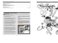
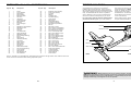
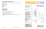
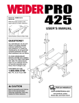
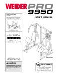
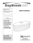
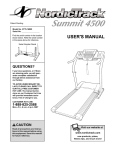
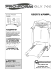
HOW TO ORDER REPLACEMENT PARTS
If you encounter any difficulties with this product, or if you need to order replacement parts, call the ICON Health
& Fitness, Ltd. office, or write:
ICON Health & Fitness, Ltd.
Customer Service Department
Unit 4
Revie Road Industrial Estate
Beeston
Leeds, LS11 8JG
UK
Model No. WLEVEX14910
Serial No.
USER'S MANUAL
Tel:
08457 089 009
Outside the UK: 0 (044) 113 387 7133
Fax: 0 (044) 113 387 7125
Serial
Number
Decal
When ordering parts, please be prepared to give the following information:
• The MODEL NUMBER of the product (WLEVEX14910)
• The NAME of the product (WESLO® PURSUIT 525 CS exercise cycle)
• The SERIAL NUMBER of the product (see the front cover of this manual)
• The KEY NUMBER and DESCRIPTION of the part(s) (see the PART LIST on page 10 of this manual).
QUESTIONS?
As a manufacturer, we are committed to providing complete
customer satisfaction. If you
have questions, or if there
are missing or damaged
parts, please call:
08457 089 009
Or write:
ICON Health & Fitness, Ltd.
Customer Service Department
Unit 4
Revie Road Industrial Estate
Beeston
Leeds, LS11 8JG
UK
Class HC Fitness Product
email: [email protected]
CAUTION
WESLO is a registered trademark of ICON Health & Fitness, Inc.
Part No. 179968 R1001A
Printed in China © 2001 ICON Health & Fitness, Inc.
Read all precautions and instructions in this manual before using
this equipment. Keep this manual
for future reference.
Visit our website at
www.weslo.com
R1001A
9
32
57
36
20
52
49
62
58
4
23
61
58
11
54
56
62
64
28
20
36
56
55
58
53
32
52
7
57
5
10
IMPORTANT PRECAUTIONS . . . . . . . . . . . . . . . . . . . . . . . . . . . . . . . . . . . . . . . . . . . . . . . . . . . . . . . . . . . . .2
BEFORE YOU BEGIN . . . . . . . . . . . . . . . . . . . . . . . . . . . . . . . . . . . . . . . . . . . . . . . . . . . . . . . . . . . . . . . . . . .3
ASSEMBLY . . . . . . . . . . . . . . . . . . . . . . . . . . . . . . . . . . . . . . . . . . . . . . . . . . . . . . . . . . . . . . . . . . . . . . . . . . .4
HOW TO OPERATE THE EXERCISE CYCLE . . . . . . . . . . . . . . . . . . . . . . . . . . . . . . . . . . . . . . . . . . . . . . . . .7
MAINTENANCE AND TROUBLESHOOTING . . . . . . . . . . . . . . . . . . . . . . . . . . . . . . . . . . . . . . . . . . . . . . . . . .8
CONDITIONING GUIDELINES . . . . . . . . . . . . . . . . . . . . . . . . . . . . . . . . . . . . . . . . . . . . . . . . . . . . . . . . . . . . .9
PART LIST . . . . . . . . . . . . . . . . . . . . . . . . . . . . . . . . . . . . . . . . . . . . . . . . . . . . . . . . . . . . . . . . . . . . . . . . . . .10
EXPLODED DRAWING . . . . . . . . . . . . . . . . . . . . . . . . . . . . . . . . . . . . . . . . . . . . . . . . . . . . . . . . . . . . . . . . .11
HOW TO ORDER REPLACEMENT PARTS . . . . . . . . . . . . . . . . . . . . . . . . . . . . . . . . . . . . . . . . . . .Back Cover
57
EXPLODED DRAWING—Model No. WLEVEX14910
35
TABLE OF CONTENTS
11
3
53
57
IMPORTANT PRECAUTIONS
7
WARNING:
26
45
59
45
59
1
60
40
30
43
33
34
24
65
17
47
46
44
2
18
42
8
39
40
25
7. Wear appropriate clothing when exercising;
do not wear loose clothing that could become
caught on the exercise cycle. Always wear
athletic shoes for foot protection.
50
59
19
13
21
6. Keep children under the age of 12 and pets
away from the exercise cycle at all times.
31
5. Inspect and properly tighten all parts regularly. Replace any worn parts immediately.
37
41
16
4. Use the exercise cycle indoors on a level surface. Keep the exercise cycle away from
moisture and dust. Place a mat under the
exercise cycle to protect the floor.
29
38
63
33
22
30
15
12. The decal shown below has been placed on
the exercise cycle. If the decal is missing, or
if it is not legible, please call our Customer
Service Department at 08457 089 009 to order
a free replacement decal. Apply the decal in
the location shown.
46 44
42 47
3. The exercise cycle is intended for home use
only. Do not use the exercise cycle in
a commercial, rental, or institutional setting.
6
11. The exercise cycle does not have a freewheel;
the pedals will continue to move until the flywheel stops.
8
2. It is the responsibility of the owner to ensure
that all users of the exercise cycle are adequately informed of all precautions.
51
13
66
10. If you feel pain or dizziness at any time whilst
exercising, stop immediately and begin cooling down.
14 23
27
1. Read all instructions in this manual before
using the exercise cycle.
12
To reduce the risk of serious injury, read the following important precautions before using the exercise cycle.
2
11
59
59
48
9. Always keep your back straight when using
the exercise cycle; do not arch your back.
31
8. The exercise cycle should not be used by
persons weighing more than 115 kg (250 lbs.).
PART LIST—Model No. WLEVEX14910
Key No. Qty.
1
2
3
4
5
6
7
8
9
10
11
12
13
14
15
16
17
18
19
20
21
22
23
24
25
26
27
28
29
30
31
32
33
34
1
1
1
1
1
1
2
2
1
1
2
1
1
1
1
1
1
1
1
2
1
1
2
1
1
1
1
1
1
2
2
2
2
1
Description
Key No. Qty.
Frame
Front Stabiliser
Seat Frame
Seat Carriage
Backrest Frame
Crank Pin
Handlebar
Flywheel Spacer
Rear Stabiliser
Backrest
Foam Handgrip
Seat
Resistance Control/Cable
Resistance Knob
Drive Belt
Console
Left Side Shield
Right Side Shield
Resistance Strap
Seat Carriage Bushing
Spring
Strap Clamp
Handlebar Endcap
Left Pedal
Return Spring
Right Pedal
Crank/Pulley
Seat Knob
Reed Switch Clamp
Crank Flange Bushing
Front Endcap
Rear Endcap
Split Bushing Set
Crank Washer
35
36
37
38
39
40
41
42
43
44
45
46
47
48
49
50
51
52
53
54
55
56
57
58
59
60
61
62
63
64
65
66
#
#
1
2
1
1
1
2
1
2
1
2
2
2
2
2
2
2
2
4
4
1
2
3
8
4
9
2
2
2
1
1
1
1
1
1
R1001A
Description
Backrest Frame Endcap
Seat Frame Endcap
Flywheel
Magnet
Flywheel Axle
Flywheel Bearing
Cable Clamp
M6 Eyebolt
Reed Switch/Wire
Adjustment Bracket
M10 Black Split Washer
M6 Nut
M8 Nylon Locknut
M10 x 85mm Carriage Bolt
M10 x 56mm Carriage Bolt
M10 Black Nylon Locknut
M10 x 75mm Button Bolt
M6 x 34mm Button Screw
M6 Nylon Locknut
M8 x 45mm Button Screw
M8 x 37mm Button Screw
M8 Split Washer
M6 x 16mm Button Screw
M5 x 7mm Screw
M4 x 16mm Screw
M4 x 25mm Screw
M10 Zinc Nylon Locknut
M10 Zinc Washer
M4 x 16mm Flat Head Screw
Seat Frame Endcap
Left Pedal Strap
Right Pedal Strap
User’s Manual
Allen Wrench
BEFORE YOU BEGIN
Congratulations for selecting the new WESLO®
PURSUIT 525 CS exercise cycle. Cycling is one of
the most effective exercises for increasing cardiovascular fitness, building endurance, and toning the entire
body. The PURSUIT 525 CS offers an impressive
array of features to let you enjoy this healthful exercise in the convenience and privacy of your home.
after reading the manual, please call our Customer
Service Department at 08457 089 009. To help us
assist you, please note the product model number and
serial number before calling. The model number is
WLEVEX14910. The serial number can be found on a
decal attached to the exercise cycle (see the front
cover of this manual).
For your benefit, read this manual carefully before
you use the exercise cycle. If you have questions
Before reading further, please familiarise yourself with
the parts that are labelled in the drawing below.
Console
Pedal
Resistance Knob
Seat
Backrest
Handlebar
Seat Carriage
Seat Knob
RIGHT SIDE
REAR
Note: “#” indicates a non-illustrated part. Specifications are subject to change without notice. See the back cover
of this manual for information about ordering replacement parts.
WARNING:
Before beginning this or any exercise program, consult your physician. This
is especially important for persons over the age of 35 or persons with pre-existing health problems.
Read all instructions before using. ICON assumes no responsibility for personal injury or property
damage sustained by or through the use of this product.
10
3
ASSEMBLY
CONDITIONING GUIDELINES
Assembly requires two persons. Place all parts of the exercise cycle in a cleared area and remove the packing
materials. Do not dispose of the packing materials until assembly is completed.
Assembly requires the included tools and your own adjustable spanner
driver
.
and Phillips screw-
Use the part drawings below to identify the small parts used in assembly. The number in parenthesis below
each drawing refers to the key number of the part, from the PART LIST on page 10. The second number refers
to the quantity needed for assembly. Note: Some small parts may have been pre-attached. If a part is not in
the parts bag, check to see if it has been pre-attached.
Aerobic Exercise
WARNING:
Before beginning
this or any exercise program, consult your
physician. This is especially important for
persons over the age of 35 or persons with
pre-existing health problems.
If your goal is to strengthen your cardiovascular system, your exercise must be “aerobic.” Aerobic exercise is activity that requires large amounts of oxygen
for prolonged periods of time. This increases the
demand on the heart to pump blood to the muscles,
and on the lungs to oxygenate the blood. For aerobic
exercise, adjust the intensity of your exercise until
your heart rate is near the highest number in your
training zone.
The following guidelines will help you to plan your
exercise program. Remember that proper nutrition
and adequate rest are essential for successful results.
HOW TO MEASURE YOUR HEART RATE
EXERCISE INTENSITY
M10 Black Nylon Locknut (50)–2
M6 Nylon
Locknut (53)–4 M10 Zinc Nylon Locknut (61)–2
M6 x 16mm Button
Screw (57)–8
M8 Split
Washer (56)–3
M10 Black Split
Washer (45)–2
M6 x 34mm Button
Screw (52)–4
M10 Zinc
Washer (62)–2
To measure your
heart rate, first
exercise for at
least four minutes.
Then, stop exercising and place two
fingers on your
wrist as shown.
Take a six-second
heartbeat count, and multiply the result by 10 to find
your heart rate. For example, if your six-second heartbeat count is 14, your heart rate is 140 beats per
minute. (A six-second count is used because your
heart rate will drop rapidly when you stop exercising.)
Whether your goal is to burn fat or to strengthen your
cardiovascular system, the key to achieving the
desired results is to exercise with the proper intensity.
The proper intensity level can be found by using your
heart rate as a guide. The chart below shows recommended heart rates for fat burning, maximum fat
burning, and cardiovascular (aerobic) exercise.
M8 x 37mm Button
Screw (55)–2
M10 x 75mm Button Bolt (51)–2
WORKOUT GUIDELINES
M8 x 45mm Button Screw (54)–1
Each workout should include the following three parts:
M10 x 56mm Carriage Bolt (49)–2
M10 x 85mm Carriage Bolt (48)–2
1. Identify the Front Stabiliser (2). Turn the Front
Stabiliser so that the warning decal is in the position
shown. Whilst another person lifts the front of the
Frame (1) slightly, attach the Front Stabiliser to the
Frame with two M10 x 85mm Carriage Bolts (48) and
two M10 Black Nylon Locknuts (50).
1
48
Decal
A warm-up, consisting of 5 to 10 minutes of stretching
and light exercise. A proper warm-up increases your
body temperature, heart rate, and circulation in preparation for exercise.
Training zone exercise, consisting of 20 to 30 minutes of exercising with your heart rate in your training
zone. (During the first few weeks of your exercise program, do not keep your heart rate in your training
zone for longer than 20 minutes.)
Burning Fat
2
1
50
4
To find the proper heart rate for you, first find your age
at the bottom line of the chart (ages are rounded off to
the nearest ten years). Next, find the three numbers
above your age. The three numbers are your “training
zone.” The lowest number is the recommended heart
rate for fat burning, the middle number is the recommended heart rate for maximum fat burning, and the
highest number is the recommended heart rate for
aerobic exercise.
A cool-down, with 5 to 10 minutes of stretching. This
will increase the flexibility of your muscles and will
help to prevent post-exercise problems.
To burn fat effectively, you must exercise at a relatively low intensity level for a sustained period of time.
During the first few minutes of exercise, your body
uses easily accessible carbohydrate calories for energy. Only after the first few minutes of exercise does
your body begin to use stored fat calories for energy.
If your goal is to burn fat, adjust the intensity of your
exercise until your heart rate is near one of the lower
two numbers in your training zone as you exercise.
EXERCISE FREQUENCY
To maintain or improve your condition, plan three workouts each week, with at least one day of rest between
workouts. After a few months of regular exercise, you
may complete up to five workouts each week, if
desired. Remember, the key to success is make exercise a regular and enjoyable part of your everyday life.
9
HOW TO OPERATE THE CONSOLE
Time, speed,
distance, or
calories
mode—To
select one of
these modes
for continuous
display, press
the mode button repeatedly. The mode indicators will show
which mode is selected. Make sure that the scan
mode is not selected.
Note: If there is a thin sheet of clear plastic on the
face of the console, remove it.
1. To turn on the power, press the mode button or
begin pedalling. The entire display will appear for
two seconds; the console will then be ready for
use.
2. Select one of the five modes:
Scan mode—
When the
power is turned
on, the scan
mode will automatically be
selected. One
mode indicator
Mode Indicators
will show that
the scan mode
is selected, and a second mode indicator will show
which mode is currently displayed. Note: If a different mode is selected, you can select the scan
mode by repeatedly pressing the mode button.
3. To reset the display, press the mode button for two
seconds. After the display is reset, the scan mode
will be selected.
4. To turn off the power, simply wait for about four
minutes. The console has an “auto-off” feature.
If the pedals are not moved and the mode button is not pressed for four minutes, the power
will turn off automatically to conserve the batteries.
2. Attach the indicated end of the Seat Frame (3) to the
Rear Stabiliser (9) with two M10 x 56mm Carriage
Bolts (49), two M10 Zinc Washers (62), and two M10
Zinc Nylon Locknuts (61).
Inspect and tighten all parts of the exercise cycle regularly. Replace any worn parts immediately.
49
3
9
62
61
62
3. Slide the Seat Carriage (4) onto the other end of the
Seat Frame (3). Make sure that the Seat Carriage is
oriented as shown. Insert the end of the Seat Frame
into the Frame (1), and attach it with two M10 x 75mm
Button Bolts (51) and two M10 Black Split Washers (45).
3
4
1
28
Insert the Seat Knob (28) into the welded nut (not
shown) on the right side of the Seat Carriage (4) and
into one of the adjustment holes in the right side of the
Seat Frame (3). Tighten the Seat Knob into the welded
nut.
4. Slide a Handlebar (7) onto one side of the Seat
Carriage (4). Attach the Handlebar with two M6 x
34mm Button Screws (52) and two M6 Nylon Locknuts
(53).
MAINTENANCE AND TROUBLESHOOTING
2
45
3
45
51
4
7
4
Attach the other Handlebar (7) to the Seat Carriage (4)
in the same way.
53
BATTERY REPLACEMENT
If the console does not function properly, the batteries
should be replaced. Refer to step 7 on page 6 for
replacement instructions. In addition, make sure that
the reed switch wire is plugged fully into the console.
Note: The console requires two 1,5 V “AA” batteries;
alkaline batteries are recommended.
To clean the exercise cycle, use a damp cloth and a
small amount of mild soap. Important: To avoid
damage to the console, keep liquids away from
the console and keep the console out of direct
sunlight.
7
5. Attach the Backrest Frame (5) to the Seat Carriage (4)
with an M8 x 45mm Button Screw (54) and an M8 Split
Washer (56) from the top, and two M8 x 37mm Button
Screws (55) and two M8 Split Washers (56) from the
bottom.
52
5
10
5
Next, attach the Backrest (10) to the Backrest Frame
(5) with four M6 x 16mm Button Screws (57).
54
56
57
4
56
55
8
5
6. Attach the Seat (12) to the Seat Carriage (4) with four
M6 x 16mmButton Screws (57).
6
HOW TO OPERATE THE EXERCISE CYCLE
12
HOW TO ADJUST THE SEAT
The seat can be
adjusted to the
position that is the
most comfortable
for you. To adjust
the seat, first
remove the seat
knob. Slide the
seat to the desired
position, and then
Seat
insert the seat
Knob
Seat
knob into the weldFrame
ed nut on the right
side of the seat
carriage and into
one of the adjustment holes in the right side of the
seat frame. Tighten the seat knob into the welded nut.
57
57
4
57
7. The Console (16) requires two 1,5 V “AA” batteries
(included). Refer to the inset drawing. Remove the battery cover from the back of the Console, and insert the
two batteries into the Console. Make sure that the
negative ends of the batteries (marked “–”) are
touching the springs in the Console. Reattach the
battery cover.
7
16
43
1
14
Next, plug the Reed Switch Wire (43) into the back of
the Console (16). Carefully slide the Console onto the
indicated tab on the Frame (1). Note: The Console is
held by friction; it does not snap into place.
13
Press the Resistance Knob (14) onto the Resistance
Control (13).
16
Batteries
Adjust the Left Pedal Strap (65) to the desired position
and press the end of the Strap onto the tab on the Left
Pedal (24). Adjust the Right Pedal Strap (not shown) in
the same way.
Speed
Bar
8
To adjust the pedal
straps, first pull the
ends of the straps
off the tabs on the
pedals. Adjust the
straps to the
desired positions,
and then press the
ends of the straps
back onto the tabs.
• Scan—This mode displays the time, speed, distance,
and calories modes, for five seconds each, in a
repeating cycle.
Strap
• Time—This mode displays the elapsed time. Note: If
you stop pedalling for five seconds, the time mode
will pause and a stop symbol will appear.
• Speed—This mode displays your pedalling speed.
Use the chart below to convert between kilometres
per hour and miles per hour.
Tab
HOW TO ADJUST THE RESISTANCE
65
27
24
9. Make sure that all parts are properly tightened before you use the exercise cycle. Note: After assembly is
completed, some extra hardware may be left over. Place a mat beneath the exercise cycle to protect the floor.
To increase the
resistance of the
Resistance
pedals, turn the
Knob
resistance knob
clockwise; to
decrease the resistance, turn the
knob counterclockwise. Important:
Stop turning the
knob when turning becomes difficult, or damage
may result.
• Distance—This mode displays the total distance that
you have pedalled. Use the chart below to convert
between kilometres and miles.
• Calories—This mode displays the approximate number of calories you have burned.
The console also features a speed bar. As you
increase your pedalling speed, additional indicators
will appear in the bar.
BATTERY INSTALLATION
Before the console can be operated, two 1,5 V “AA”
batteries must be installed. Refer to step 7 on page 6
for installation instructions.
6
Display
The console features five modes that provide instant
exercise feedback during your workouts:
HOW TO ADJUST THE PEDAL STRAPS
Battery
Cover
8. Identify the Left Pedal (24), which is marked with an
“L.” Using an adjustable wrench, firmly tighten the
Left Pedal counterclockwise into the left arm of the
Crank (27). Tighten the Right Pedal (not shown) clockwise into the right arm of the Crank. Important:
Tighten both Pedals as firmly as possible. After
using the exercise cycle for one week, retighten the
Pedals. For best performance, the Pedals must be
kept tightened.
DESCRIPTION OF THE CONSOLE
7