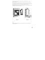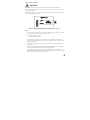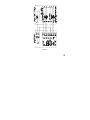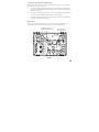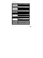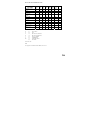
1
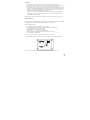
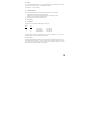
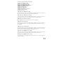
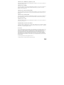
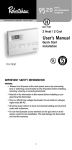
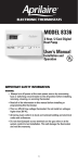
RC-100BZ Heat Pump 2 Stage Heat / 1 Stage Cool Thermostat Installation Instructions DESCRIPTION The RC-100BZ is a precision digital thermostat designed for 24 VAC heat pump systems. It has the capability of being controlled both locally and by remote control over a Z-Wave network. It offers programmability, stand-alone operation, and communications with automation systems, utility control systems, or personal computers over a Z-Wave network. The RC-100ZB is equipped with a “cool blue” backlight display. Electrical rating: Maximum current: Thermostat operating current: 24 V; 3 A; 50/60 Hz 2 A on any circuit, 3 A total less than 15 mA The following requirements must be observed for installation in Europe: CE 1. This equipment must be installed in accordance with National wiring rules for the country in which it is installed. 2. Fuses must be replaced only with IEC rated components. 3. All product labels, instructions and markings relating to safety must be translated to a language, which is acceptable in the country in which this equipment is to be installed. INSTALLATION Before installing this thermostat: 1. 2. 3. 4. 5. 6. Read all of the installation instructions carefully. Read the Owner's Manual carefully. Ensure that this product is suitable for your application. Ensure that wiring complies with all codes and ordinances. Disconnect power to the control transformer to prevent electrical shock and damage to equipment. Select an appropriate location to ensure an accurate temperature reading. Location When replacing an existing thermostat, install the RC-100BZ in the same location. If the existing location doesn't meet the following criteria, choose a new location. When choosing a location for the thermostat: 1. 2. 3. 4. Ensure that the thermostat is mounted 5 feet above the floor and is at least 2 feet from an outdoor wall. Ensure that the thermostat is located in an area where there is adequate air circulation. Do not mount in the path of direct sunlight or of radiant heat generated by appliances. Do not mount behind an outdoor wall, near a fireplace, or in the path of any air ducts. Document Number 13I00-61 / Rev A / May, 2007 Copyright © 1999-2007 Home Automation, Inc. All Rights Reserved 1 Removing an existing thermostat 1. Disconnect the power to the control transformer. 2. Remove the cover to the existing thermostat. 3. Disconnect the wires going to each terminal on the thermostat. Label each wire with the letter or number at the terminal. 4. Remove the existing plate or base from the wall. MOUNTING When mounting the RC-100BZ, grasp the thermostat by the sides, avoiding the keys, and unsnap the base from the face. Holding the base to the wall so that the word "TOP" is upright and facing you: 1. 2. 3. 4. 5. Mark the two mounting holes on the wall using a pencil. Drill a hole using a 3/16" bit at each mounting hole marking. Install the two wall anchors supplied. Slide the system wires through the opening in the base. Mount the base to the wall using the two #6 x 1/2" self-tapping screws supplied - See Figure 1. Figure 1 2 Connect each wire to the terminal strip on the thermostat base per the wiring diagram for your system application - See Figures 4 - 5. Form the thermostat wiring so that the cable lies flat between the terminal strip and the center of the base. Upon completion of wiring the thermostat, push all excess wiring into the hole in the wall. Plug the hole with the supplied insulating foam to ensure an accurate temperature reading by the thermostat. Align the tabs of the thermostat face with the slots of the thermostat base. Gently push the thermostat face into the thermostat base locking it into place - See Figure 2. Figure 2 Figure 3 Note: Be sure that the thermostat temperature sensor is standing up, and that it has not been damaged during installation - See Figure 3. 3 TYPICAL WIRING DIAGRAMS CAUTION: Be sure to disconnect the power to the control transformer before removing or installing thermostat. Do not short compressor relay, fan relay, auxiliary heat relay, or reversing valve...even momentarily. This will blow a non-replaceable fuse. Do not attempt to hook up to live circuits. An accidental connection to a component on the thermostat circuit board could cause damage to the thermostat. Figure 4 - Thermostat power-up for test or demonstration purposes NOTES 1) As a convenience to the installer, the compressor start up protection delay can be canceled. To cancel the delay, press the Prog key 3 times, then press the Fan key 2 times. 2) "O" Terminal is energized for cooling "B" Terminal is energized for heating In most applications, the reversing valve is energized for cooling and should be connected to the "O" terminal. If the heat pump requires the reversing valve to be energized for heating, connect the reversing valve to the "B" terminal. 3) "X1" and "X2" are connected to a 24VAC Red LED, most often used to indicate a fault with the heat pump compressor. 4) The Emergency Heat Relay (E Terminal) and outdoor thermostats (usually accessories to a heat pump), are not used. The RC-100BZ automatically controls auxiliary heat efficiently. The RC-100BZ requires at least 1 stage of auxiliary heat enabled at all times. If the heat pump is equipped with an outdoor thermostat, it should be removed from the auxiliary heat circuit, or reconfigured so that it can only disable 2nd and 3rd stage of auxiliary heat. 4 Figure 5 5 CONFIGURING THE BACKLIGHT ON THE RC-100BZ The backlight on the RC-100BZ can be configured to one of three different modes: 1) on for 30 seconds when a key is pressed, 2) always on, or 3) always off. 1) To configure the display backlight to turn on when a key is pressed, then back off 30 seconds later, set the “JP2” (Select Backlight Mode) jumper to the “TIMED” position (between the top and middle pin on the connector) - See Figure 6. 2) To configure the display backlight to always be on, set the “JP2” (Select Backlight Mode) jumper to the “ON” position (between the middle and bottom pin on the connector) - See Figure 6. 3) To configure the display backlight to never come on (always off), remove the “JP2” (Select Backlight Mode) jumper from the connector - See Figure 6. DISABLE KEYS The keys on the thermostat can be disabled to prevent anyone from controlling the thermostat locally. To disable the keys, solder a wire jumper across “JP1” (two holes on the circuit board) - See Figure 6. TO DISABLE KEYS LOCALLY SOLDER WIRE JUMPER HERE SELECT BACKLIGHT MODE (SET JUMPER) Figure 6 6 POWER UP 1. 2. 3. 4. Double check wiring, be sure that there are no stray wires or wire strands at the connections. Connect power to the transformer and system. The display will show all segments for about 5 seconds. Press the Fan key. The fan should come on. Press the Fan key again. The fan should go off. Set the Mode to "HEAT". Use the up arrow key to raise the desired temperature setting above the current temperature. Ensure that the heat pump comes on, in heating mode. After a few minutes, set the mode to "EM HEAT". The heat pump should stop and the auxiliary heating should come on. Set the mode to OFF. Ensure that both the heat pump and auxiliary heat go off. 5. Set the Mode to "COOL". Use the down arrow key to lower the desired temperature setting below the current temperature. Ensure that the heat pump comes on, in cooling mode. Set the mode to "OFF". Ensure that the cooling unit goes off. If the thermostat or system does not perform as stated above, recheck all wiring - See Troubleshooting Tips. INSTALLER SETUP This section describes the items that the installer must setup as part of the thermostat installation. The Installer Setup mode is used to configure the general operating parameters of the thermostat. When in Installer Setup mode: 1. 2. 3. 4. 5. 6. 7. The small digits on the top of the display are the item number. The large blinking digits in the center of the display are the value of the item number. Press the Prog (>) key to advance to the next item. Press the Hold (<) key to return to the previous item. Use the arrow keys (∧−∨) to change the value of each item. Do not set the values to anything other than the specified range for each item. To exit Setup mode, press the Fan key. The thermostat will automatically exit Setup mode after 20 seconds of no key activity. To enter the Installer Setup mode, press the Prog key three times (day will flash), then press the Fan key. The word "default" indicates the initial setting when the thermostat is delivered from the factory. 7 00 Address If you are using Communications Mode 0 or 1, and you are installing more than one thermostat, each must be set to a consecutive address, starting at 1. The default address setting is 1. An address from 1- 127 may be selected. 01 Communications mode The thermostat can communicate with remote systems in 4 different modes. These modes are: 0 1 8 24 300 baud, RS-232 mode (for use with personal computers) 100 baud, Z-Wave mode (OmniLT, Omni, Omni II, OmniPro, and OmniPro II systems) PESM mode, (use with Model 1503 automation systems) Day/Night mode (for use with remote setback switch) The default setting is 1. 02 System options The thermostat can be configured with the following system options: WITH EEC 0 1 4 5 NO EEC* 8 9 12 13 Auto changeover Auto changeover Manual changeover Manual changeover no fan with heat fan on with heat no fan with heat fan on with heat * Energy Efficient Control (EEC) of Auxiliary Heat: Select 0, 1, 4, and 5 to enable EEC, or 8, 9, 12, and 13 to disable EEC display. See Owner's Manual for description of EEC. The default setting is 1. In most heat pump installations, the auxiliary heat is electric resistance heat and the Energy Efficient Control (EEC) should be turned on (settings 0, 1, 4, and 5). If the heat pump is equipped with a more efficient auxiliary heat, such as hot water supplied by a gas water heater, you may want to turn EEC off (settings 8, 9, 12, and 13). The thermostat will act like a conventional 2 stage thermostat. 8 03 Display options The thermostat can be configured to display the following attributes: 0 1 2 3 4 5 6 7 Celsius Fahrenheit Celsius Fahrenheit Celsius Fahrenheit Celsius Fahrenheit am/pm time format am/pm time format 24-hour time format 24-hour time format am/pm time format am/pm time format 24-hour time format 24-hour time format programmable programmable programmable programmable non-programmable non-programmable non-programmable non-programmable When communicating with an HAI controller, the thermostat should be configured as "non-programmable". To disable the clock and filter reminder displays, add “16” to each value. The default setting is 1. 04 Calibration offset This item is used to raise or lower the current temperature reading by 1 degree Fahrenheit or 1/2 degree Celsius. If this item is set to 30, no change will be made. Each digit below 30 will lower to temperature, and each digit above 30 will raise the temperature. (1 = “- 29” to 59 = “+ 29” temperature units; 30 = No change) The default setting is 30. 05 Cool setpoint limit This item is used to limit the temperature setting in cool mode. The desired cool setting can never be set below this setting. The default setting is 51. 06 Heat setpoint limit This item is used to limit the temperature setting in heat mode. The desired heat setting can never be set above this setting. The default setting is 91. 07 Not used 08 Not used 09 Not used 10 Not used 9 11 Cooling minimum on/off time (minutes) This item is used to limit the on and off times of the cooling system. When the cooling system starts, it must remain on for the minimum time set by this item. When the cooling system turns off, it must remain off for a minimum time set by this item. Setting 5 6 7 8 10 Cycles per hour (maximum) 6 5 4 3.7 3 The recommended setting is 8 minutes. A higher setting may be appropriate for buildings with low heat loss/gain. The default setting is 8. 12 Heating minimum on/off time (minutes) This item is the same as the “Cooling minimum on/off time”, but for the heating system. The default setting is 8. 13 Stage 2 Differential This item specifies the temperature difference between stage 1 heating (the heat pump) and stage 2 heating (auxiliary heat). The default setting of 2 (degrees F) is recommended for all applications. In special cases a setting of 3 or 4 may be used when precise control of temperature is not as important as highest energy efficiency, however, the thermostat will not be able to maintain temperature within 1 degree of its setting under cold weather conditions. A setting of 1 or 0 is not recommended. In this thermostat, the automatic anticipator will compensate for the temperature "droop" caused by the stage 2 differential under cold weather conditions. 14 Clock adjust If the clock on the thermostat is running faster or slower than the actual time, you can have the thermostat automatically compensate up to 29 seconds per day. The thermostat will add or subtract the selected amount of time daily. (1 = “- 29” to 59 = “+ 29” seconds per day; 30 = No change) The default setting is 30. Note: If an HAI automation system is being used, the controller system time is sent to the thermostat every minute. This adjustment will have no effect. 10 15 Filter reminder The thermostat logs the amount of time the system fan has been running. When this setting reaches 0, the thermostat will display a reminder to replace the filter. The setting is the amount of days (24 hours of system operation) before this reminder is displayed. Days - Counting down from 10 - 0 The filter reminder can be disabled by setting this item to 60. 16 System runtime (This week) This item logs the amount of time (hours) that the heating and cooling system was in operation this week. 17 System runtime (Last week) This item logs the amount of time (hours) that the heating and cooling system was in operation last week. ANTICIPATION RC-100BZ anticipation is performed electronically and is independent of the type and load of the components in the heating and cooling equipment. The RC-100BZ has electronic control based on proportional, integral, and derivative components and maintains temperature to within 1 degree F. of the setting. Anticipation is not adjustable on the RC-100BZ. OWNER'S MANUAL Following Installer Setup, check the option boxes () in the Owner's Manual according to the configuration of the thermostat. 11 QUICK-REFERENCE SETUP GUIDE This table displays each Installer Setup item with its default setting. The column labeled "CURRENT" can be used to write down the current settings if any changes are made to the default settings. Item Number 00 01 02 03 04 05 06 07 08 09 10 11 12 13 14 15 16 17 Description Address Communication mode System options Display options Calibration offset Cool setpoint limit Heat setpoint limit Not used Not used Not used Not used Cooling minimum on/off time Heating minimum on/off time Stage 2 Differential Clock adjust Filter reminder System runtime (This week) System runtime (Last week) Default 1 1 1 1 30 51 91 8 8 2 30 10 - Current WIRELESS COMMUNICATIONS WITH HAI CONTROLLER This thermostat has been preprogrammed with energy saving settings recommended under the EPA Energy Star program. When used with remote systems, HAI recommends that the thermostat be configured as "nonprogrammable" (See Setup Item 03 - "Display Options"). HAI AUTOMATION SYSTEMS The thermostat can communicate with an HAI automation system over a Z-Wave network. The controller can send commands to the thermostat to change mode, cool setting, heat setting, status of fan and hold, and other items. ADDING A THERMOSTAT TO THE Z-WAVE NETWORK When prompted by Z-Wave primary or inclusion controller to include the thermostat to the network, press and release the ‘Hold’ button on the thermostat. This will include the thermostat on the Z-Wave network. REMOVING A THERMOSTAT FROM THE Z-WAVE NETWORK When prompted by Z-Wave primary or inclusion controller to exclude the thermostat from the network, press and release the ‘Hold’ button on the thermostat. This will exclude the thermostat from the Z-Wave network. 12 The thermostat supports the following command classes: COMMAND_CLASS_THERMOSTAT_MODE COMMAND_CLASS_THERMOSTAT_SETPOINT COMMAND_CLASS_THERMOSTAT_FAN_MODE COMMAND_CLASS_THERMOSTAT_FAN_STATE COMMAND_CLASS_THERMOSTAT_OPERATING_STATE COMMAND_CLASS_SENSOR_MULTILEVEL COMMAND_CLASS_ASSOCIATION COMMAND_CLASS_CONFIGURATION COMMAND_CLASS_VERSION COMMAND_CLASS_MANUFACTURER_SPECIFIC COMMAND_CLASS_SWITCH_BINARY COMMAND_CLASS_CLOCK COMMAND_CLASS_THERMOSTAT_MODE Upon power up, allow 10 seconds for the RC-100BZ thermostat to initialize. After 10 seconds, a controller can set the mode, get the current mode, and get the modes supported by the thermostat. COMMAND_CLASS_THERMOSTAT_SETPOINT Upon power up, allow 10 seconds for the RC-100BZ thermostat to initialize. After 10 seconds, a controller can change setpoints, get current setpoints, and request the setpoints that are supported by thermostat. COMMAND_CLASS_SENSOR_MULTILEVEL The RC-100BZ thermostat uses this command class to report the actual temperature. COMMAND_CLASS_ASSOCIATION Upon power up, allow 10 seconds for the RC-100BZ thermostat to initialize. After 10 seconds, a controller can issue an Association Set, Remove, or Get command. The thermostat must be associated with a controller to provide feedback. COMMAND_CLASS_CONFIGURATION Upon power up, allow 10 seconds for the RC-100BZ thermostat to initialize. After 10 seconds, a controller can change individual register settings for the outdoor temperature. The Parameter Number is 67. The size of the data is a 1 byte value. The Value is the temperature to which the register is set. COMMAND_CLASS_THERMOSTAT_FAN_MODE Upon power up, allow 10 seconds for the RC-100BZ thermostat to initialize. After 10 seconds, a controller can set the fan mode, get the current fan mode, and get the fan modes supported by the thermostat. COMMAND_CLASS_THERMOSTAT_FAN_STATE Upon power up, allow 10 seconds for the RC-100BZ thermostat to initialize. After 10 seconds, a controller can request the state of the fan. 13 COMMAND_CLASS_THERMOSTAT_OPERATING_STATE Upon power up, allow 10 seconds for the RC-100BZ thermostat to initialize. After 10 seconds, a controller can request the Operating State report. COMMAND_CLASS_VERSION Upon power up, allow 10 seconds for the RC-100BZ thermostat to initialize. After 10 seconds, a controller can request a Version Report. This report includes information about the library type, protocol, version, and application version from the device. COMMAND_CLASS_MANUFACTURER_SPECIFIC Upon power up, allow 10 seconds for the RC-100BZ thermostat to initialize. After 10 seconds, a controller can request a Manufacturer Specific Info Report. This report will return the Manufacturer ID, Product Type, and Product ID. COMMAND_CLASS_SWITCH_BINARY Upon power up, allow 10 seconds for the RC-100BZ thermostat to initialize. After 10 seconds, a controller can turn on the Hold feature by sending a Binary Switch On command and turn off the Hold feature by sending a Binary Switch Off command. COMMAND_CLASS_CLOCK Upon power up, allow 10 seconds for the RC-100BZ thermostat to initialize. After 10 seconds, a controller can set the time of the internal clock INTEROPERABILITY WITH Z-WAVE™ DEVICES A Z-Wave™ network can integrate devices of various classes, and these devices can be made by different manufacturers. The RC-100BZ thermostat can be incorporated into existing Z-Wave™ networks. All listening Z-Wave nodes act as repeaters regardless of vendor. FCC NOTICE Note: This equipment has been tested and found to comply with the limits for a Class B digital device, pursuant to part 15 of the FCC Rules. These limits are designed to provide reasonable protection against harmful interference in a residential installation. This equipment generates, uses, and can radiate radio frequency energy and, if not installed and used in accordance with the instructions may cause harmful interference to radio communications. However, there is no guarantee that interference will not occur in a particular installation. If this equipment does cause harmful interference to radio or television reception, which can be determined by turning the equipment off and on, the user is encouraged to try to correct the interference by one or more of the following measures: - Increase the separation between the equipment and receiver. - Consult the dealer or an experienced radio/TV technician for help. 14 TROUBLESHOOTING TIPS SYMPTOM Thermostat Dead ACTION TO TAKE 1. Check power to the thermostat 2. Check wiring diagrams 3. Check thermostat temperature sensor Thermostat will not operate with a damaged temperature sensor SYMPTOM Fan, Heat, Or Cool Inoperative ACTION TO TAKE 1. Check for break in G, W, or Y wire 2. Allow minimum off time to pass 3. Check system options for correct settings 4. Remote system is overriding thermostat "REMOTE" is displayed when system is overriding thermostat. SYMPTOM Can't Adjust Temperature ACTION TO TAKE 1. Mode is Off (Select Heat, Cool, or Auto) 2. Check if thermostat keys are disabled To enable thermostat keys for test, remove jumper SYMPTOM Control By Remote System Not Working ACTION TO TAKE 1. Check Node ID 2. Check communications mode setting 3. Check setup of the remote system Ensure that all setup items for the thermostat and the remote system are set to the proper configurations for communication SYMPTOM Temperature Reading Incorrect 1. 2. ACTION TO TAKE Allow 30 minutes for thermostat to adjust to room temperature Adjust calibration offset Change setup option to display oF or oC 3. After installation, allow the thermostat up to 30 minutes for an accurate temperature reading SYMPTOM Display Problem ACTION TO TAKE Disconnect power to the thermostat. Reconnect, then observe display self-test For a 5 second period after power is reconnected, all segments of the display should light indicating all thermostat functions 1. 15 HEAT PUMP CROSS REFERENCE GUIDE RC-100BZ CARRIER, PAYNE DAY&NIGHT TRANE COLEMAN 3000 SERIES COMFORTMAKER CYC SERIES GOETTL HP HEIL QUAKER 867, PH50 LENNOX * HP19, HP20 LENNOX CB19 RHEEM / RUDD PGB, PFA, PCB WEATHERTRON YORK - E1CS, E1FB, E1FH R (1) G (2) O (3) B (4) C (5) Y (6) W2 (7) B X2 R G O C Y1 W2 L R R G G O O BLUE X Y Y W W2 C L O R G R R G G C Y W1 O X C Y Y F R X M W2 W1 W2 Y V VR R R L G G O O C X Y Y W1 W2 L L R R G G O O B B Y Y W-U W X B RC-100BZ TERMINAL DESCRIPTIONS R G O B C Y W2 (1): (2): (3): (4): (5): (6): (7): (8): 24VAC "HOT" FAN REV VALVE (COOLING) REV VALVE (HEATING) 24VAC COMMON COMPRESSOR AUXILIARY HEAT NOT USED X2 FAULT LED Note: X1 is jumped to C terminal in the RC-100BZ, if X2 is in use. 16