1
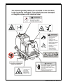
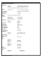
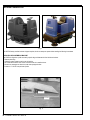
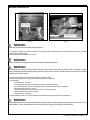
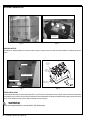
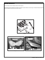
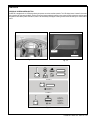
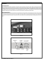
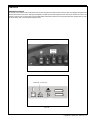
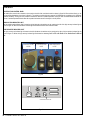
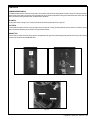
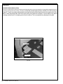
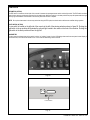
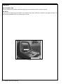
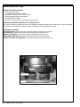
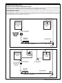
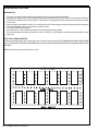
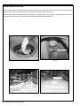
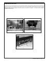
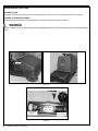
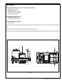
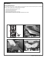
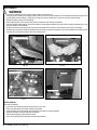
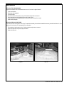
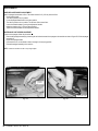
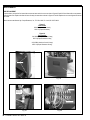
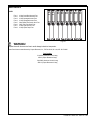
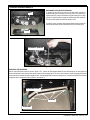
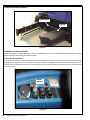
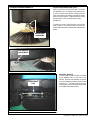
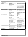
SR5730
INSTRUCTIONS FOR USE
Models 505-945, 505-946, 505-959
5/08 FORM NO. 56041764
TABLE OF CONTENTS
Introduction ..................................................................................................... 4
Cautions and Warnings .................................................................................. 5
Symbols .......................................................................................................... 6
Specifications .............................................................................................. 8-9
Machine Preparation .............................................................................. 10-13
Controls ................................................................................................... 14-22
Lcd Display ....................................................................................... 15
Scrub Brush Switch .......................................................................... 16
Scrub Pressure Switch ..................................................................... 16
Squeegee/Vacuum Switch ................................................................ 17
Solution Flow Control Knob .............................................................. 18
Low Solution Indicator Light ............................................................. 18
High Recovery Indicator Light .......................................................... 18
Forward/Reverse Switch .................................................................. 19
Key Switch ....................................................................................... 19
Foot Pedal ....................................................................................... 19
Horn Button ...................................................................................... 19
Secondary Brake (Option) ............................................................... 20
Esp (Option) ..................................................................................... 21
Lights (Option) ................................................................................. 21
Hour Meter ........................................................................................ 21
Seat Adjustment Lever ..................................................................... 22
Seat Switch ....................................................................................... 22
Operating Instructions ............................................................................ 23-30
Pre-Start Checklist ............................................................................ 23
Filling The Solution Tank ................................................................... 23
Starting The Machine ........................................................................ 23
Transporting The Machine ................................................................ 23
Beginning The Cleaning Operation ................................................... 24
Machine Safety Features .................................................................. 24
Standard Scrubbing System ............................................................. 25
Esp (Recyling) Scrubbing System .................................................... 25
Helpful Hints For The Cleaning Operation ........................................ 26
Stopping The Cleaning Operation..................................................... 26
Post-Operation Checklist .................................................................. 27
Draining The Recovery Tank............................................................. 27
Cleaning And Inspecting The Machine ........................................ 28-29
Pre-Sweep Attachment (Option) ....................................................... 30
Maintenance ............................................................................................ 31-43
Maintenance Schedule ..................................................................... 31
Battery Charging ............................................................................... 33
Battery Removal ............................................................................... 34
Replacing Scrub Brushes ................................................................. 35
Replacing Pads................................................................................. 35
Squeegee Caster Adjustment ........................................................... 36
Squeegee Maintenance .................................................................... 36
Squeegee Blade Replacement ......................................................... 37
Drain Solution Tank ........................................................................... 37
Side Broom Belt ................................................................................ 37
Fuse Replacement....................................................................... 38-39
Cylindrical Scrub Brush Maintenance & Replacement ..................... 40
Cylindrical Scrub Deck Belt Maintenance & Replacement ............... 41
Side Squeegee Maintenance & Replacement .................................. 41
Hopper Maintenance ........................................................................ 42
Side Broom Replacement ................................................................. 43
Dual Side Brooms (Option) Operation & Maintenance ..................... 43
Troubleshooting ............................................................................................ 44
FORM NO. 56041764 - SR5730 - 3
INTRODUCTION
This manual will help you get the most from your American-Lincoln automatic scrubber/dryer. Read it thoroughly before operating the machine.
This product is intended for commercial use only.
PARTS AND SERVICE
Repairs, when required, should be performed by your Authorized American-Lincoln Service Center, who employs factory trained service personnel,
and maintains an inventory of American-Lincoln original replacement parts and accessories.
Call American-Lincoln for repair parts or service. Please specify the Model and Serial Number when discussing your machine.
(Dealer, affix service sticker here.)
NAMEPLATE
The Model and Serial Number of your machine are shown on the Nameplate in the battery compartment. This information is needed when ordering
repair parts for the machine. Use the space below to note the Model and Serial Number of your machine for future reference.
Model _________________________________________
Serial Number ___________________________________
UNPACKING THE MACHINE
When the machine is delivered, carefully inspect the shipping packaging and the machine for damage. If damage is evident, save the shipping
carton (if applicable) so that it can be inspected. Contact the American-Lincoln Customer Service Department immediately to file a freight damage
claim. Refer to the unpacking instruction sheet included with the machine to remove the machine from the pallet.
4 - FORM NO. 56041764 - SR5730
CAUTIONS AND WARNINGS
SYMBOLS
American-Lincoln uses the symbols below to signal potentially dangerous conditions. Always read this information carefully and take
the necessary steps to protect personnel and property.
DANGER!
Is used to warn of immediate hazards that will cause severe personal injury or death.
WARNING!
Is used to call attention to a situation that could cause severe personal injury.
CAUTION!
Is used to call attention to a situation that could cause minor personal injury or damage to the machine or other property.
Read all instructions before using.
GENERAL SAFETY INSTRUCTIONS
Specific Cautions and Warnings are included to warn you of potential danger of machine damage or bodily harm.
*
*
*
*
*
*
*
*
*
*
*
*
*
*
*
*
*
*
*
*
*
*
WARNING!
This machine shall be used only by properly trained and authorized persons.
While on ramps or inclines, avoid sudden stops when loaded. Avoid abrupt sharp turns. Use low speed down hills. Clean only
while ascending (driving up) the ramp.
Keep sparks, flame and smoking materials away from batteries. Explosive gases are vented during normal operation.
Charging the batteries produces highly explosive hydrogen gas. Charge batteries only in well-ventilated areas, away from open
flame. Do not smoke while charging the batteries.
Remove all jewelry when working near electrical components.
Turn the key switch off (O) and disconnect the batteries before servicing electrical components.
Never work under a machine without safety blocks or stands to support the machine.
Do not dispense flammable cleaning agents, operate the machine on or near these agents, or operate in areas where flammable
liquids exist.
Do not clean this machine with a pressure washer.
Only use the brushes provided with the appliance or those specified in the instruction manual. The use of other brushes may
impair safety.
CAUTION!
This machine is not approved for use on public paths or roads.
This machine is not suitable for picking up hazardous dust.
Do not use scarifier discs and grinding stones. American-Lincoln will not be held responsible for any damage to floor surfaces
caused by scarifiers or grinding stones (can also cause damage to the brush drive system).
When operating this machine, ensure that third parties, particularly children, are not endangered.
Before performing any service function, carefully read all instructions pertaining to that function.
Do not leave the machine unattended without first turning the key switch off (O), removing the key and applying the parking
brake.
Turn the key switch off (O) and remove the key, before changing the brushes, and before opening any access panels.
Take precautions to prevent hair, jewelry, or loose clothing from becoming caught in moving parts.
Use caution when moving this machine in below freezing temperature conditions. Any water in the solution, recovery or detergent
tanks or in the hose lines could freeze, causing damage to valves and fittings. Flush with windshield washer fluid.
The batteries must be removed from the machine before the machine is scrapped. The disposal of the batteries should be safely
done in accordance with your local environmental regulations.
Do not use on surfaces having a gradient exceeding that marked on the machine.
All doors and covers are to be positioned as indicated in the instruction manual before using the machine.
SAVE THESE INSTRUCTIONS
FORM NO. 56041764 - SR5730 - 5
6 - FORM NO. 56041764 - SR5730
FORM NO. 56041764 - SR5730 - 7
TECHNICAL SPECIFICATIONS
POWER SUPPLY
SR5730 (34”)
SR5730 (38”)
36 volt (6-6 volt batteries) 340 AH or 370 AH
36 volt (6-6 volt batteries) 340 AH or 370 AH
For machine to operate properly, voltage reading should fall within 32-40 vdc.
CHARGER
SR5730 (34” & 38”)
36 vdc output, 115V/60Hz or 230V/50Hz Input
MOTORS, VACUUM
1 HP (.74 kw), 3 stage, tangential discharge
MOTORS, BRUSH
1.7 hp (1.3kw)
MOTOR, DRIVE
1.5 hp (1.1kw)
WHEELS
(1) Front 12.0” (31.8 cm) (2) rear 12.0” (31.8 cm)
BRUSH SIZE
SR5730 DISC (34”)
SR5730 DISC (38”)
SR5730 CYLINDRICAL (34”)
2-17” (43.2 cm) DIA.
2-19” (48.3 cm) DIA.
2-6” DIA. x 34” LONG
SR5730 (34“)
SR5730 (38”)
34” (86.4 cm)
38” (96.5 cm)
CLEANING PATH
BRUSH SPEED
300 RPM
SOLUTION TANK
45 gallon (171 liter)
RECOVERY TANK
45 gallon (171 liter)
SPEED, TRANSPORT
5 MPH
SPEED, SCRUBBING
2.5 MPH
TURN RADIUS
56” (142.2 cm)
U-TURN AISLE WIDTH
80” (203.2 cm)
CLEANING RATE
SR5730 (34”)
SR5730 (38”)
37,000 sq. ft/hr (3426 sq. m/hr)
42,000 sq. ft/hr (3901 sq. m/hr)
GRADE CLEANING
3°
GRADE TRANSPORT
8°
LENGTH
71.5” (181.6 cm)
WIDTH
SR5730 (34”)
Machine
Brush Housings
Squeegee
33.5” (85 cm)
38.0” (96.5 cm)
42.0” (106.7cm)
SR5730 (38”)
Machine
Brush Housings
Squeegee
33.5” (85 cm)
41.0” (104.1 cm)
42.0” (106.7 cm)
HEIGHT
51” (129.5 cm)
HEIGHT W/OHG
80” (203.2 cm)
WEIGHT
SR5730 (34”)
SR5730 (38”)
8 - FORM NO. 56041764 - SR5730
1800 lb. (817.2 kg)
1820 lb. (826.3 kg)
FORM NO. 56041764 - SR5730 - 9
MACHINE PREPARATION
Fig. 1
Your SR5730 battery machine has been shipped complete, but do not attempt to operate without reading the following instructions:
UNPACKING AND ASSEMBLING MACHINE
The SR5730 is shipped on a pallet covered by a plastic bag and fastened with four hold down brackets.
1. Remove plastic bag.
2. Unbolt lag screws located on each corner of machine.
3) Lift out bracket located on each corner of machine from slot in machine frame.
4) Remove rear squeegee and hose from under rear squeegee location.
6) Position a 11° and 36” ramp on base of pallet.
11 DEGREE
36 INCHES
Fig. 2
10 - FORM NO. 56041764 - SR5730
MACHINE PREPARATION
DISCONNECT TRACTION
HARNESS CABLE BEFORE
TOWING THE MACHINE
METAL BAR
BRAKE RELEASE LEVER
Fig. 3
ELECTRICALLY ACTUATED
MECHANICAL PARKING BRAKE
Fig. 4
WARNING!
Disconnect the traction harness before towing the machine.
7) The machine is shipped with a metal bar between the electrically actuated parking brake and the brake release lever to keep the electrically
actuated parking brake disengaged.
8) Push machine down the ramp onto a flat surface.
WARNING!
Remove the metal bar to engage the electrically actuated mechanical parking brake.
WARNING!
BEFORE towing or pushing this machine, disconnect the traction harness and reinsert the metal bar used for shipping (or similar
device) to deactivate the electromagnetic braking system. Failure to do so will result in premature wear of the friction disc or possible
destruction of the braking system.
9) Connect rear squeegee hose and install squeegee blade as shown in manual.
10) Remove battery charger from under the seat in battery compartment (if applicable).
11) Install batteries.
-Turn the key to the “O” position
-Lift the hinged seat and cover, then disconnect seat switch and remove seat plate.
-Use a battery lifting device with a 150 LB. (68KG) capacity to place the batteries battery compartment.
-Install Battery wires as shown in manual.
-Plug the polarized connector from the battery on into the 36 Volt plug provided.
-Install scrub brushes as shown in the manual.
-Lower seat and cover assembly.
12) Charge batteries as shown in the manual. Read battery manufacturer literature for battery care and maintenance.
WARNING!
Do not charge batteries on a concrete grounded surface. Hydrogen gas is formed during the charging operation and is explosive. Only
charge batteries in a well ventilated area with the lid open. Avoid any smoking, open flame, or electrical sparks.
FORM NO. 56041764 - SR5730 - 11
MACHINE PREPARATION
REMOVE BATTERY
FROM BOX
Fig. 6
Fig. 5
UNPACKING BATTERY
The batteries are shipped separately in six boxes as shown in figure 5. Open the boxes on a clean work surface and lift out the battery as shown in
figure 6.
6 VOLT
LEAD ACID
BATTERY
SAFETY LATCH
BATTERY
CONNECTOR
WIRE
BATTERY COMPARTMENT
BATTERY SPACER
(NARROW SIDE UP)
BATTERY CONNECTOR
BATTERY SPACER
(NARROW SIDE UP)
SIDE PANEL
Fig. 7
Fig. 8
BATTERY INSTALLATION
To install batteries lift the seat cover and secure safety latch in notch. Pull up on the side panel and remove to gain access to the battery compartment.
Lower batteries using a 1000 lb. (454 KG) lifting mechanism to lift and install batteries into battery compartment placing battery spacers to stop from
moving. Connect battery connector wires in series to batteries as shown in figure 8.
WARNING!
Do not leave charged batteries on concrete surface, they will discharge.
12 - FORM NO. 56041764 - SR5730
MACHINE PREPARATION
Connect the battery connector assembly to battery as shown in figure 9.
Plug the battery connector assembly from the battery to the machine connector assembly as shown in figure 10. Reinstall the side panel and then
release the safety latch and lower the seat as shown in figure 11.
CONNECTOR
ASSEMBLY
(TO BATTERY)
Fig. 9
CONNECT BATTERIES
Fig. 10
LOWER SEAT TO
COVER BATTERIES
Fig. 11
FORM NO. 56041764 - SR5730 - 13
CONTROLS
1.
2.
3.
4.
5.
6.
7.
8.
9.
10.
11.
12.
13.
Solution Flow Knob
Brush Switch (for cylindrical with dual side broom option, see Chapter 4)
Low Solution Light (Left) High Recovery Light (Right)
Scrub Pressure Switch
Squeegee Vacuum Switch
ESP
Light Switch, Optional
LCD Display
Forward/Reverse Switch
Key Switch
Secondary Optional Brake Pedal (Bottom), Pedal Lock (Top)
Horn Button, Optional
Foot Throttle
8
1
9
3
2
5
4
7
6
12
11
Fig. 12
14 - FORM NO. 56041764 - SR5730
13
10
CONTROLS
LCD DISPLAY SCREEN CONTROL BUTTON
The SR5730 is equipped with an LCD display allowing the operator to monitor machine operation. The LCD display button is located in the center
of the console to the right under the display. Pushing on the menu button enables the operator to view screen functions and monitor machine status
and operation. When the key switch is turned on, screen 1 will automatically be displayed. Pressing the menu button will allow you to review screens
2 and 3.
CONSOLE
LCD DISPLAY
MENU BUTTON
Fig. 13
Fig. 14
SCREEN 1
SCREEN 2
SCREEN 3
Fig. 15
FORM NO. 56041764 - SR5730 - 15
CONTROLS
SCRUB BRUSH SWITCH
The scrub brush switch is located on the left side of the console to right of the solution control knob as shown in figure 16. Pushing the scrub brush
switch to up position will raise the scrub deck to the top position, the scrub brushes will stop rotating, the water solenoid will de-energize and solution
flow will stop. Pushing the scrub brush switch down will lower the scrub deck to the set down pressure. The squeegee will lower and the vacuum will
activate. When the scrub brush and squeegee are on, they will be displayed as shown in figure 17. The brushes will not rotate until the foot throttle
is depressed. Releasing the foot throttle will raise the scrub deck to the top position and the brushes will stop rotating.
SCRUB PRESSURE SWITCH
The scrub pressure switch is located on the left side of the console between scrub brush switch and the squeegee/vacuum switch as shown in figure
16. Pushing the scrub pressure switch up selects the next highest scrub setting available, increasing pressure. Selected pressure is displayed as a
bar on the LCD control panel. Pressing the scrub pressure switch down selects the next lowest setting available, decreasing pressure as shown in
figure 17.
BRUSH SWITCH
SCRUB
PRESSURE
SWITCH
Fig. 16
BATTERY STATUS
METER
SCRUBBING
DOWN
PRESSURE
SCRUB
BRUSHES ON
SOLUTION
FLOW ON
Fig. 17
16 - FORM NO. 56041764 - SR5730
DECK SCRUBBING
PRESSURE METER
SOLUTION
FLOW
METER
CONTROLS
SQUEEGEE/VACCUM SWITCH
The squeegee vacuum switch is located on the left side of the console to the right of the scrub brush switch as shown in figure 18. Pushing the squeegee/vacuum
switch up raises and turns off the vacuum. Pushing the squeegee/vacuum switch down lowers the squeegee and turns on the vacuum. When the vacuum is on, it is
displayed as shown in figure 19. Pressing down on the foot throttle with the forward/reverse switch in the reverse position will raise the squeegee when it is down.
The vacuum will turn off in 15 seconds after the squeegee is raised.
SQUEEGEE
VACUUM
SWITCH
Fig. 18
SQUEEGEE VACUUM ON
Fig. 19
FORM NO. 56041764 - SR5730 - 17
CONTROLS
SOLUTION FLOW CONTROL KNOB
The solution flow control knob is located on the console to the left of the scrub brush switch as shown in figure 20. When solution flow is on, the
flow rate will be displayed as a bar shown in figure 21. The solution control knob gives an output of 0-3 GPM with disc scrubbing and 0-1 GPM with
cylindrical scrubbing. Turning the knob clockwise increased the amount of solution deposited. Turning the knob counterclockwise decreases the
amount of solution deposited. Solution flow will stop when the brushes are off or the key is in the off position.
LOW SOLUTION INDICATOR LIGHT
The low solution amber indicator light is located on the left side above the switches on the console to the left of the high recovery indicator light as
shown in figure 20. When the low solution indicator light illuminates the solution tanks need to be filled.
HIGH RECOVERY INDICATOR LIGHT
The high recovery red indicator light is located on the left side above the switches on the console to the right of the low solution indicator light as
shown in figure 21. When the high recovery indicator light illuminates the recovery tank is full and needs to be drained and cleaned
out.
SOLUTION FLOW
KNOB
LOW SOLUTION
LIGHT
HIGH RECOVERY
LIGHT
Fig. 20
SOLUTION FLOW ON
Fig. 21
18 - FORM NO. 56041764 - SR5730
CONTROLS
FORWARD/REVERSE SWITCH
The forward/reverse switch is located on the right side of the console to right side of the steering wheel as shown in figure 22. Pushing the forward/
reverse switch up will result in the machine moving forward when the foot throttle is depressed. Pushing the forward/reverse lever switch down will
result in the machine moving backward when the foot throttle is depressed.
KEY SWITCH
The key switch turned to the right, the ”I” position, will activate all machine systems as shown in figure 23.
FOOT PEDAL
The foot pedal is located on the floor on the right side as shown in figure 24. Pressing the foot pedal down sets the machine in forward or reverse
motion, the direction depending on the position of the forward/reverse switch.
HORN BUTTON
The horn button is located on the floor of the operator’s compartment to the right of the optional parking brake pedal as shown in figure 24. Pressing
the button with the left foot will activate the horn.
FORWARD
REVERSE
SWITCH
KEY SWITCH
Fig. 22
Fig. 23
HORN BUTTON
FOOT PEDAL
Fig. 24
FORM NO. 56041764 - SR5730 - 19
CONTROLS
SECONDARY PARKING BRAKE (OPTION)
The machine is equipped with an electrically actuated mechanical parking brake on the front drive wheel that is automatically engaged when the key
is turned off or the drive wheel stops rotating. A secondary, mechanically actuated parking brake is available as an option as shown
in figure 25. To set the secondary parking brake, press down the brake and then press the lock on the upper portion of the
pedal. To unlock the parking brake, push on the upper portion of the pedal lock to release it. The foot brake is not a method
for slowing machine travel or for stopping under normal conditions. This is accomplished by releasing the foot pedal.
PEDAL LOCK
BRAKE PEDAL
Fig. 25
20 - FORM NO. 56041764 - SR5730
CONTROLS
ESP SWITCH (OPTION)
The ESP switch is located on the left side of the console in between the squeegee/vacuum switch and the light switch. The ESP switch transfers
water from the recovery tank through a filter and into the solution tank. When the switch is in the down position the pump will operate when the high
recovery light is illuminated. Clean the filter in the recovery tank when the tank is emptied.
NOTE: Do not place clean water in the recovery tank when using the ESP option, the solution tank could become overfilled during operation.
LIGHT SWITCH (OPTION)
The light switch is located on the left side of the console to the left of the steering wheel as shown in
figure 26. Pushing the
light switch to the up position will illuminate the optional light located in the center on the front of the machine. Pushing the
light switch to the down position will turn the light off.
HOUR METER
The hour meter is activated when the key switch is in the “on” position. Screen 2 on the LCD display shows total hours and panel screen display 3
shows total hours, brush hours and traction hours. This is useful for determining service intervals.
LIGHT SWITCH
ESP
Fig. 26
HOUR METER
Fig. 27
FORM NO. 56041764 - SR5730 - 21
CONTROLS
SEAT ADJUSTMENT LEVER
This lever is located on front to the seat to the left allowing the seat to be moved forward and back as shown in figure 28.
SEAT SWITCH
The seat switch is a interlock safety switch located on the underside the seat and is activated by the operator’s body weight while seated. The
machine will stop immediately if there is no operator present in the seat.
SEAT SWITCH
SEAT ADJUSTMENT LEVER
Fig. 28
22 - FORM NO. 56041764 - SR5730
OPERATING INSTRUCTIONS
NOTE: Before starting, perform the pre-start checks.
PRE-START CHECKLIST
1. Check controls for proper operation.
2. Make sure all controls are in the off position
3. Be sure foot throttle is in the neutral position
4. Check all flaps for damage or wear
5. Check scrub brushes for wear
6. Fill solution tank with water and detergent
TO FILL SOLUTION TANK
Remove the solution lid located on the back right side of the machine as shown in figure 30. Fill tank with 40 gallons of water and the correct mixture
of American Lincoln Commercial cleaner for the job on hand, first making sure that the solution control knob is “OFF.” Place the lid back
on the solution tank.
TO START MACHINE
1. Release secondary parking brake (if equiped).
2. Turn key to “I” position.
TO TRANSPORT MACHINE
1. Make sure the brushes and squeegees are in the up or raised position with all other controls in the off position.
2. Push the forward/reverse switch to desired position (up for forward and down for reverse)
3. Push down on the foot throttle to obtain desired travel speed, release foot throttle to stop.
WARNING!
Do not turn the steering wheel sharply when the machine is in motion. The sweeper is very responsive to movement of the steering
wheel. Do not make sudden turns.
SOLUTION TANK
RECOVERY TANK
Fig. 30
FORM NO. 56041764 - SR5730 - 23
OPERATING INSTRUCTIONS
TO BEGIN THE CLEANING OPERATION
1. Lower brushes into position.
DISC SCRUB DECK = NORMAL OR HEAVY
CYLNDRICAL SCRUB DECK = ONE SETTING ONLY
2. Place the squeegee switch in the lower position.
SQUEEGEE BLADE = LOWER
3. Move solution control knob to the desired setting and begin operation.
SCRUBBING THE AVERAGE FLOOR WITH LIGHT TO MEDIUM SOILAGE
In this operation, cleaning is accomplished in one pass, with simultaneous solution feed, scrubbing and dirty water pick up. The rate of solution feed
and the speed of travel required will vary with floor condition. This knowledge will come with operator experience.
MACHINE SAFETY FEATURES:
SEAT SAFETY SWITCH - Machine will not move and parking brake will set if this switch is not activated.
SPEED INTERLOCK - Maximum machine speed will be reduced while scrub brushes are in use.
BRUSHES OFF IN NEUTRAL - Scrub brushes automatically disengage when machine is idle.
PARKING BRAKE INTERLOCK - Parking brake will automatically set when foot pedal is released.
AUTOMATIC RECOVERY VACUUM SHUT-OFF - Vacuum fans will shut down when recovery tank is full.
DRAIN HOSE
BRUSHES
SQUEEGEE HOSE
SQUEEGEE
Fig. 31
24 - FORM NO. 56041764 - SR5730
OPERATING INSTRUCTIONS
THE NON-RECYCLING OR STANDARD SCRUBBING MODE – FIGURE 32
During the scrubbing process, detergent solution water from the solution tank is fed to the solution line. There it is fed to the floor where two disc scrubbing brushes
work to dislodge soil. After scrubbing, the dirty solution is vacuumed from the floor and discharged into the recovery tank.
Sensors in each tank will indicate, by lights on the control panel, when the water in the solution tank is too low or when the water in the recovery tank is too high.
ESP OPERATING MODE – FIGURE 33
During the scrubbing process, filtered water from the solution tank is fed to the solution line and then to the floor where two disc scrubbing brushes work to dislodge
soil. After scrubbing, the dirty solution is vacuumed from the floor and discharged into the recovery tank. At intervals, a float switch activates the recycling pump,
which sends filtered solution from the recovery tank to the solution tank.
Fig. 32
SOLUTION
TANK
RECOVERY
TANK
STRAINER
SOLUTION
CONTROL
VALVE
SCRUB
BRUSH
SQUEEGEE
FLOOR CONTACT
Fig. 33
SOLUTION
TANK
SOLUTION
CONTROL
VALVE
SOLUTION
PUMP
STRAINER
RECOVERY
TANK
STRAINER
SCRUB
BRUSH
SQUEEGEE
FLOOR CONTACT
FORM NO. 56041764 - SR5730 - 25
OPERATING INSTRUCTIONS
SCRUBBING PATH
*
*
*
*
*
*
Try to scrub in as straight a path as possible. Avoid bumping into posts or scraping the sides of the machine.
When placing the machine in motion, avoid slamming the directional control pedal all the way forward suddenly. This is equivalent to starting out
in “HIGH” and puts needless strain on the drive system. Periodically, turn the sweeping broom end for end to prevent the bristles from “settling”
in one direction.
Plan your sweeping and scrubbing in advance. Try to arrange long runs with minimum stopping and starting. Sweep debris from narrow aisles
out into main aisle ahead of time. Do an entire floor, or section at on time.
Pick up oversize debris before sweeping.
Allow a few inches of overlap of sweep and scrub paths. This will eliminate leaving dirty patches.
Don’t turn steering wheel to sharply when machine is in motion. The machine is very responsive to movement of the steering wheel; so avoid
sudden turns.
TO STOP THE CLEANING OPERATION
Discontinue the cleaning operation when the low solution light or the high recovery light illuminates, this indicates the solution tank is empty
or recovery tank is full. Discontinue the scrubbing cycle, put all controls in the forward position for transport and drive to the
drain area.
NOTE: After stopping, perform these post operation checks.
Fig. 34
26 - FORM NO. 56041764 - SR5730
OPERATING INSTRUCTIONS
POST-OPERATION CHECKLIST
Check Battery Condition and recharge, if necessary.
1. Check all flaps for wear, damage and adjustment.
2. Drain and clean recovery tank.
3. Clean recovery tank screen and float.
4. Check scrub brushes for wear or damage.
5. Check rear and side squeegee for wear, damage and adjustment.
DRAIN HOSE PLUG
DRAIN HOSE PLUG
DRAIN HOSE
DRAIN HOSE
Fig. 35
Fig. 36
DRAINING RECOVERY TANK
Fig. 37
TO DRAIN RECOVERY TANK
The drain hose for the recovery tank is located on the back of the machine. To drain the tank, remove and lower the hose and place in a suitable floor
drain as shown in figure 37. Open the drain hose plug as shown in figure 35 and 36.
IMPORTANT!
Improper discharge of wastewater will damage the environment and is illegal. The U.S. Environmental Protection Agency has established
certain regulations regarding discharge of wastewater. The local city and state regulations regarding wastewater discharge may be in
effect in your area. Understand and follow the regulations in your area. Be aware of the environmental hazards associated with the
substances you dispose of.
FORM NO. 56041764 - SR5730 - 27
OPERATING INSTRUCTIONS
When the draining operation is completed, flush the recovery drain hose as shown in figure 38. Clean the recovery tank and recovery tank screen
as shown in figure 39. Close the drain hose plug, close recovery tank lid and clip the drain hose into place.
Inspect the disc brushes and replace when bristles are reduced to 3/4 inch length as shown in figure 40 and 41. To order replacement brushes, see
scrub brush options in this manual. (IF YOUR 5730 HAS CYLINDRICAL SCRUBBING, SEE CHAPTER 4.)
RECOVERY TANK SCREEN
RECOVERY TANK HOSE
Fig. 39
Fig. 38
DISK SCRUB BUSHES
SQUEEGEE PIN
BRUSH BRISTLES
SHOULD NOT
BE LESS THAN
3/4” HIGH
SIDE SQUEEGEE
DISK SCRUB BRUSH
Fig. 40
28 - FORM NO. 56041764 - SR5730
Fig. 41
OPERATING INSTRUCTIONS
Inspect the rear and side squeegee blades for wear. If the wiping edge has become rounded, remove and reinstall so the unworn edge is now the
wiping edge. This process can be repeated until all four edges are worn. If the squeegee blade has become rippled, it will need to be replaced.
Inspect the inner flap on the rear squeegee for wear and to ensure it has not been torn or damaged. (IF YOUR 5730 HAS CYLINDRICAL
SCRUBBING, SEE CHAPTER 4.)
REAR SQUEEGEE
SQUEEGEE BLADE
Fig. 43
Fig. 42
SIDE SQUEEGEE
Fig. 44
FORM NO. 56041764 - SR5730 - 29
OPERATING INSTRUCTIONS
PRE-SWEEP (OPTION)
The sweeper is designed to turn the broom on as it is lowered as shown in figure 45. To lower the broom release hand lever on right side.
PRE-SWEEP FILTER BAG REPLACEMENT
The filter bag should be checked every time the pre sweep is used and replaced when full as shown in figure 46.
WARNING!
There is a potential risk of the bag tearing and causing premature failure of the dust control motor and the main and side broom
motor.
HAND LEVER
Fig. 45
SIDE BROOM
REPLACE BAG
WHEN FULL
DUST CONTROL
MOTOR
MAIN AND SIDE
BROOM MOTOR
Fig. 46
30 - FORM NO. 56041764 - SR5730
MAINTENANCE
EVERY 8 HOURS or DAILY operation check and clean/adjust if necessary:
1. All flaps for wear or damage
2. Clean recovery tank
3. Scrub brushes for wear or damage
4. Rear squeegee for wear or damage
5. Charge and check batteries
50 HOUR MAINTENANCE CHECKLIST:
6. Check battery electrolyte level
7. Lubricate steering bearing and pivot
100 HOUR MAINTENANCE CHECKLIST:
8. Clean solution tank
For service assistance, consult your local American-Lincoln Distributor, For best performance, replace worn parts with genuine American-Lincoln
parts.
Refer all Maintenance and Service Requirements to Qualified Maintenance Personnel.
Do not attempt to service this machine until you have read and understood all Safety Warnings associated with the equipment you are working on.
5, 6
8
PINCH POINT
KEEP CLEAR
WARNING
PINCH POINT
KEEP CLEAR
WARNING
4
WARNING
WARNING
BATTERY BOX CAN SLIDE OFF
FORK LIFT.
MAY CAUSE SERIOUS PERSONAL
INJURY OR PROPERTY DAMAGE.
TIE SECURELY TO FORKS DURING
TRANSPORT. DRIVE AND STOP
WITH CAUTION.
BATTERY COVER COULD CLOSE UNEXPECTEDLY
AND CAUSE PERSONAL INJURY.
Engage Safety Latch Before Working in this area.
7
1, 3
2
Fig. 47
FORM NO. 56041764 - SR5730 - 31
MAINTENANCE
For safety, read and follow the service precautions below. Know the hazards associated with the equipment you are working on to prevent personal
injury or damage to equipment.
For service assistance, consult your nearest American-Lincoln dealer. For best performance replace worn parts with genuine American-Lincoln
parts.
Refer all maintenance and service requirements to qualified maintenance personnel.
DO NOT attempt to service this machine until you have read and understand all safety warnings associated with the equipment you are working
on.
*
*
*
*
*
*
*
*
*
*
*
WARNING!
Maintenance and repairs must be done by authorized personnel only.
Electrical repairs must be done by authorized personnel only. Consult your American-Lincoln Authorized Service Person to do service
procedures. Use only genuine American-Lincoln parts.
Always park on a level surface, turn key off, and engage parking brake before working on the machine to keep it from creeping or rolling.
If towing or pushing is required, disconnect motor lead located on the terminal block on the bottom of the machine.
Maintenance and repairs must be done by authorized personnel only. Always empty the solution tank and the recovery tank before doing any
maintenance. Keep all fasteners tight. Keep adjustments according to the specifications as shown in the Service Manual for this machine.
Always wear eye protection and protective clothing when working near batteries. Do not put tools or other metal objects across the topes of the
batteries. NO SMOKING.
To prevent damage to the machine, and discharge across the tops of the batteries, do not fill the batteries above the bottom of the tube in each
cell. Wipe any acid from the machine or the tops of the batteries. Do not add acid to a battery after installation.
Always wear eye protection and protective clothing when working near batteries. NO SMOKING.
Always empty the hopper and disconnect the batteries before doing any maintenance.
The hopper could fall and cause serious injury. Always engage the hopper safety arm before working under the hopper.
To maintain the stability of this machine in normal operation, the overhead guard, or similar equipment installed by the manufacturer as original
equipment should not be removed. If it becomes necessary to remove such equipment for repair or maintenance, this equipment must be
reinstalled before machine is placed back in operation.
32 - FORM NO. 56041764 - SR5730
MAINTENANCE
BATTERY CHARGING INSTRUCTION
When the batteries are disconnected (i.e. charging, replacement), the microprocessor needs to be reset by turning the key switch on and raising the
brush deck. When the red light comes on steady the batteries can be charged.
1.
2.
3.
4.
5.
Lift seat cover, make sure safety latch is secure in notch.
Insert charging plug into battery receptacle.
Plug power cord into proper AC source.
Follow the charging instructions provided on the charger.
Maintain electrolyte level in batteries, check after charging. Add distilled water as needed.
LIFT SEAT TO ACCESS BATTERIES
-
+
+
+
+
+
-
-
+
-
+
- +
-
BATTERY
CHARGER
Fig. 48
Fig. 49
SAFETY LATCH
CONNECT BATTERIES
Fig. 50
Fig. 51
FORM NO. 56041764 - SR5730 - 33
MAINTENANCE
*
*
*
*
*
*
*
WARNING!
Do not remove the battery from the machine if there is waste in the solution tank.
Hydrogen gas is formed during the charging operation and is explosive! Only charge batteries in a well-ventilated area with the lid open. Avoid
any open flame or electrical sparks. Pulling out the charger plug, with the charger still on, will cause an arc and must be avoided.
Batteries are heavy. Get help to lift the batteries.
Always remove jewelry, wear protective clothing, and face protection when working near batteries.
Lead acid batteries generate gases, which cause explosions. Keep sparks and flames away from batteries charge the batteries only in area
with good ventilation. NO SMOKING!
To prevent an explosion, disconnect the AC plug from the receptacle before connection or disconnection the DC plug on the charger.
The battery box can slide off a forklift and cause severe personal injury or damage to equipment. Ensure that the battery box is properly secured
to the forks of the forklift during transport, drive and stop with caution.
LIFT SEAT TO ACCESS BATTERIES
DISCONNECT BATTERIES
Fig. 52
Fig. 53
DISCONNECT
BATTERY CONNECTOR WIRE
SAFETY LATCH
BATTERY COMPARTMENT
BATTERY CONNECTOR
SIDE PANEL
Fig. 54
BATTERY REMOVAL
When removing batteries
1. Lift the seat cover making sure the safety latch is secure in the notch.
2. Remove the side panel to gain access to battery compartment.
3. Unplug the battery connector assembly from the battery to the machine connector assembly.
4. Disconnect the battery connector wires from the batteries.
5. Remove battery spacers holding batteries in place.
6. Use a 100 lb. (454 KG) lifting mechanism to lift and remove batteries.
34 - FORM NO. 56041764 - SR5730
Fig. 55
MAINTENANCE
REPLACING THE SCRUB BRUSHES
Replace Scrub Brushes when the bristles become worn to 3/4” as shown in figure 56 and 57.
1.
2.
3.
4.
5.
6.
7.
Lower scrub brushes.
Swing open side squeegees
Lift scrub brushes
The scrub brush is held in place by a ring. Pull the brush straight down to remove it.
Push a new brush onto the scrub brush driver until it clicks in place.
Lower Scrub Deck to the NORMAL position and check the brush for proper floor contact.
Replace side squeegees.
REPLACING PADS ON A PAD DRIVER
Install a new pad when the old pad is worn or dirty. The pad driver assembly is removed and installed the same way a standard scrub brush is. (See
replacing the scrub brushes) To change pad follow this procedure.
1.
2.
3.
The pad driver is held in place by a ring. Pull the pad driver straight down to remove it.
Remove the pad holder using the spring wire retainer.
Replace the worn pad.
DISK SCRUB BUSHES
SQUEEGEE PIN
BRUSH BRISTLES
SHOULD NOT
BE LESS THAN
3/4” HIGH
SIDE SQUEEGEE
DISK SCRUB BRUSH
Fig. 56
Fig. 57
FORM NO. 56041764 - SR5730 - 35
MAINTENANCE
SQUEEGEE CASTER WHEEL ADJUSTMENT
Adjust if squeegee leaves water on floor. The wheels must be 3/16” (.476 cm) above the floor.
1. Set the parking brake.
2. Turn the key switch to the on position.
3. Put the Squeegee Blade Switch in the lower position.
4. Turn the key switch to the on position. This will turn off the vacuum fans.
5. Loosen the wheel brackets by turning the adjustment handles.
6. Adjust the wheels to 3/16” (.476 cm) above the floor.
7. Tighten the wheel brackets with the adjustment handles.
MAINTENANCE FOR THE REAR SQUEEGEE
To remove the squeegee, follow this procedure:
1. Remove the squeegee assembly by loosening the two knobs that attach the squeegee to the machine as shown in figure 59. Pull the squeegee
assembly off.
2. Inspect the squeegee blade.
3. If the blade is worn, turn the blade so that a new edge is in the wiping position.
4. Reinstall squeegee assembly on the machine.
NOTE: Toothed lock washers must be on top of support plate
ADJUSTMENT
CASTORS
SQUEEGEE KNOB
Fig. 58
36 - FORM NO. 56041764 - SR5730
Fig. 59
MAINTENANCE
SQUEEGEE BLADE REPLACEMENT
Replace if front or rear blades are worn or damaged.
1. Set the parking brake.
2. Turn the key to the on position.
3. Put the Squeegee Blade Switch in the lower position.
4. Turn the key switch to the off position.
5. Remove the rear squeegee assembly.
6. Loosen the strap clamp.
7. Remove the old blades.
Push the new blades in until they are against the top of the squeegee. Retighten
clamp
TO DRAIN SOLUTION TANK
Remove the cover from the solution tank, rotate the handle on the drain plug
counterclockwise and then pull up as shown in figure 61. After the tank has drained,
flush out with clean water and reinstall the plug.
PRE SWEEP (OPTION)
Main Broom Belt
1. Check belt tension adjustment as shown in figure 62.
2. Loosen idler pulley as shown in figure 63.
3. Move in slot in main frame.
4. Retighten.
SIDE BROOM BELT
1. Check belt tension adjustment as shown in figure 64.
2. Loosen pulley and broom nut.
3. Force pulley and broom forward.
4. Retighten.
SQUEEGEE CLAMP
Fig. 60
PLUG
Fig. 61
MAIL BROOM BELT
Fig. 62
TO TIGHTEN BELT
PUSH DOWN
LOOSEN NUT
TO ADJUST BELT
PULL FORWARD TO TIGHTEN BELT
SIDE BROOM BELT
IDLER PULLEY
LOOSEN NUT
TO ADJUST BELT
Fig. 63
Fig. 64
FORM NO. 56041764 - SR5730 - 37
MAINTENANCE
FUSE REPLACEMENT
To replace fuses, unscrew the four internal hex screws and remove the front cover as shown in figures 65 and 66. Check fuses with an amp meter to
locate the blown fuse. Replace the fuse with one of exactly the same size as shown in figures 67 and 68. Replace the cover and tighten the internal
hex screws.
These fuses are manufactured by: Cooper-Bussmann, Inc., P.O. Box 14460, St. Louis, MO 63178-4460
Figure 67
Fuse Part No.
8-28-05019 (American-Lincoln)
ACK-70 (Cooper Bussmann)
Figure 68
Fuse Part Nos.
2-00-05861 (American-Lincoln/2 amp)
ABC-2 (Cooper Bussmann/2 amp)
2-00-05860 (American-Lincoln/10 amp)
ABC-10 (Cooper-Bussmann/10 amp)
INTERNAL HEX SCREW
FRONT COVER
Fig. 65
Fig. 66
2 AMP FUSES
70 AMP FUSE
FOR BATTERY
SHORT CIRCUIT
PROTECTION
10 AMP FUSES
Fig. 67
38 - FORM NO. 56041764 - SR5730
Fig. 68
MAINTENANCE
FUSES
Fuse 1
Fuse 2
Fuse 3
Fuse 4
Fuse 5
Fuse 6
Fuse 7
Fuse 8
10 Amp Scrub Deck Actuator Fuse
10 Amp Scrub Deck Actuator Fuse
10 Amp Squeegee Actuator Fuse
10 Amp Squeegee Actuator Fuse
2 Amp Water Flow Control Valve Fuse
2 Amp Tank Float Switch Fuse
10 Amp Light and Horn Fuse
10 Amp Option Pump Fuse
FU1 FU2 FU3 FU4 FU5 FU6 FU7 FU8
Fig. 69
WARNING!
Replace fuses with the same size fuse to avoid damage to electrical components.
Power Panel fuses are manufactured by: Cooper-Bussmann, Inc., P.O. Box 14460, St. Louis, MO 63178-4460
Fuse Part Nos.
2-00-05861 (American-Lincoln/2 amp)
ABC-2 (Cooper Bussmann/2 amp)
2-00-05860 (American-Lincoln/10 amp)
ABC-10 (Cooper-Bussmann/10 amp)
FORM NO. 56041764 - SR5730 - 39
CYLINDRICAL MAINTENANCE
MAINTAINING THE SCRUB DECK BRUSHES
SIDE GUARD LATCH
SCRUB DECK
OPEN SIDE GUARD
Figure 1
Figure 2
Locate the Side Guard Latch on the (operator’s) right side of the machine. Facing the side guard, push the latch to the right to release and open
the guard.
COVER PLATE KNOBS
COVER PLATE
Figure 3
Figure 4
Locate the Cover Plate on the scrub deck; loosen the knobs holding the plate in place by turning counterclockwise, then remove the cover.
Firmly grasping one of the brushes, remove it for inspection*. Check
the brushes for wear and
damage. Remove any entangled debris. Turn the brush end-toend, line up knotches, and reinsert. Repeat with the second brush.
NOTE: Rotating brushes will extend the life of the brush.
Brushes should be replaced when bristles are worn to 3/4-inch
length. (See scrub brush options in this chapter).
Reattach cover and close side guard.
*The manufacturer recommends using handprotection.
Figure 5
40 - FORM NO. 56041764 - SR5730
CYLINDRICAL MAINTENANCE
BELT
MAINTAINING THE SCRUB DECK BRUSHES
To access the scrub deck belt, open the left side guard, unscrew the
hardware holding the cover panel, then remove panel. To set belt tension,
slightly loosen the 2 bolts from behind the triagular metal piece in which
they are set. Move this piece to tighten or loosen the belt, then reset bolts.
Test tension and readjust until pressure reading is 2 lbs.
To replace, loosen until belt is easily removed. Replace with new belt and
follow same procedure as above. Reinstall cover and close side guard.
COVER
Figure 6
TO ADJUST TENSION
Figure 7
MAINTAINING THE SQUEEGEES
Open the right and left side guards as shown in figures 1 & 2. Inspect the side squeegee blades for wear and damage. If the wiping edge has
become rounded, detach from guard by removing the screws from the squeegee strap. Turn so the unworn edge is now the wiping edge and reinstall.
This process can be repeated until all four edges are worn. If the squeegee blade has become gouged or torn, it should be replaced.(The same rear
squeegee is used on cylindrical and disc scrubbers - see Chapter 1.)
SQUEEGEE STRAP
SCREWS
SQUEEGEE
Figure 8
FORM NO. 56041764 - SR5730 - 41
CYLINDRICAL MAINTENANCE
SCRUB DECK
HOPPER
Figure 9
MAINTAINING THE SCRUB DECK HOPPER
Open the left side guard. The hopper, which slides in and out, is located behind the scrub deck. Remove the hopper and empty debris. Hose out
remaining residue and reinsert behind deck. Close side guard.
THE DUAL SIDE BROOM OPTION
If you have chosen to equip your 5730 Cylindrical Scrubber with the dual side broom option, the brush control switch on the instrument panel will
look slightly different. The switch will be a 3-way. When the top portion of the switch is depressed, the scrub brushes and side brooms are off; in the
center position, the scrub brushes only are activated; and when the bottom of the switch is pressed, both the side brooms and the scrub brushes
are put into operation.
BRUSH
SWITCH
Figure 10
42 - FORM NO. 56041764 - SR5730
CYLINDRICAL MAINTENANCE
THE DUAL SIDE BROOM OPTION (CON’T)
Check the side brooms for wear and damage. The brooms
are deliberately set at a downward angle (back-to-front)
in order to enhance debris collection, rotating toward the
center of the machine and throwing soil toward the hopper
at the rear of the scrub deck. To adjust the brooms, turn the
knob clockwise to raise or counterclockwise to lower.
(See figure 12)
To replace the brooms, remove the three nuts and bolts
shown in figure 11, insert bolts through new broom and
reinstall. Adjust with knob if necessary after replacing both
brooms.
SIDE BROOM
HARDWARE
Figure 11
SIDE BROOMS
ADJUSTMENT
Figure 12
ADJUSTMENT
ROD
ADJUSTING THE DECK
The front-to-back tilt of the scrub deck is controlled
by the adjustable rods on both sides of the
machine. The rods can be adjusted in (to tilt back)
or out (to tilt forward) by loosening the jam nut and
turning the rod. The width of the front and rear
brush pattern on the floor should be roughly equal
at the middle down-pressure setting.
Figure 13
FORM NO. 56041764 - SR5730 - 43
TROUBLESHOOTING
Problem
Probable Cause
Poor Scrubbing
1. Worn scrub brushes.
2. Incorrect method of operation.
3. Wrong cleaning agent or mixture.
4. Poor solution distribution.
5. Brushes won’t turn.
Water splashes from sides of scrub deck.
1. Scrub deck bumpers, poor contact with floor.
2. Squeegee blades worn or damaged.
3. Too much solution.
1. Broom jammed.
2. Hopper full.
3. Broom does not turn
4. Hopper not installed correctly.
5. Poor broom pattern.
6. Flaps worn.
Poor sweeping (Option).
Machine moves slow or erratically.
1. Battery charge low.
2. Brakes dragging.
3. Loose connection at foot pedal.
4. Overload of drive circuit.
Machine does not move.
Poor water pick up at squeegee
Water spills from squeegee
Squeegee leaves wet spots
Squeegee makes excessive noise
44 - FORM NO. 56041764 - SR5730
1. Blown fuse.
2. Battery unplugged.
1. Recovery tank full
2. Squeegee is worn or damaged
3. Clogged suction hose or pick up tool
4. Loose connections between suction hose and
squeegee
5. Vacuum motors not running
6. Plugged filter
7.Vacuum float cage clogged
8. Vacuum float shut off
9. Air leaks in suction hose and connection
10. Air leaks at recovery tank cover and/or
manifold hose
11. Drain hose or drain plug leaking or not closed
properly
1. Side squeegee blades have poor contact with
floor
2. Squeegee blades worn or damaged
3. Too much solution being applied before making
turns
4. Brushes rotating opposite direction
1. Lift actuator out of adjustment
2. Squeegee wheels out of adjustment
1. Blades worn or damaged
Remedy
1. Replace brushes when scrub reaches worn zone.
Brushes should be replaced when bristles worn to
¾”.
2. Check scrubbing procedure, brush pressure, type
of cleaning agent and solution flow-all are important
to the scrubbing process.
3. Use American-Lincoln recommended cleaning
materials.
4. Check solution strainer and clean feed hoses
for obstructions. Check valve control for proper
operation.
5. Check wiring connections.
1. Readjust blades for proper contact.
2. Replace and adjust.
3. Shut off solution flow 5’ to 10’ before making turns.
1. Remove obstruction.
2. Empty.
3. Adjust or replace broom belts. Reset circuit
breakers adjust broom micro switches. Repair loose
wire connections.
4. Reinstall.
5. Adjust sweep pattern.
6. Repair or replace.
1. Change.
2. Adjust.
3. Repair.
4. Remove obstruction, put drive pedal in neutral.
5. Adjust.
1. Check fuse and replace if necessary.
2. Plug in battery.
1. Empty tank
2. Examine squeegee rubber blade for cuts or worn
spots/replace if necessary
3. Disconnect suction hose from squeegee; flush
squeegee and hose thoroughly
4. Check all hose connections for looseness or
damage
5. Reset circuit breaker or repair loose connection
6. Clean filter element in vacuum manifold
7. Clean perforated metal thoroughly
8. Excessive foam build up; change cleaning
chemical mixture (use A-L approved material)
9. Repair or replace hose and connections
10. Repair or replace seal and hose
11. Close, repair or replace drain plug in recovery
tank
1. Readjust blades for proper contact
2. Replace and adjust blades
3. Shut off solution flow 5-10 feet pior to making turn
4. Check position of switches
1. Adjust
2. Adjust
1. Replace
14600 21st Avenue North
Plymouth, MN 55447-3408
www.americanlincoln.com
Phone:
800-331-7692
Fax:
877-877-2586
©2008 American-Lincoln