1
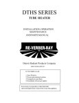
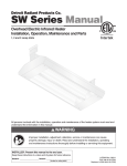
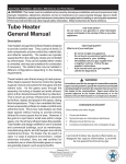
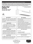
TUBE HEATER
TROUBLESHOOTING GUIDE
MODELS: SV Series Tube Heaterer
THESE HEATERS MUST BE INSTALLED AND SERVICED BY TRAINED GAS INSTALLATION
AND SERVICE PERSONNEL ONLY. READ AND UNDERSTAND ALL INSTRUCTIONS
THOROUGHLY BEFORE ATTEMPTING TO INSTALL, OPERATE OR SERVICE THE DETROIT
RADIANT PRODUCTS COMPANY HEATER. FAILURE TO COMPLY WITH THESE
WARNINGS AND INSTRUCTIONS, AND THOSE ON THE HEATER, COULD RESULT IN
PERSONAL INJURY, DEATH, FIRE, ASPHYXIATION AND/OR PROPERTY DAMAGE.
RETAIN THESE INSTRUCTIONS FOR FUTURE REFERENCE.
CAUTION! Heater may be hot. Do not store or use gasoline or other flammable
vapors and liquids in the vicinity of this or any other appliance. Note presence of
flammable gas and electrical shock hazard.
WARNING! Extinguish open flame while servicing heaters. Test for gas leaks with
soap and water solution only. Wear safety glasses while servicing unit.
FOR YOUR SAFETY!
IF YOU SMELL GAS:
1. Open windows.
2. Do not touch electrical switches.
3. Extinguish any open flame.
4. Immediately call your gas supplier.
SHUTDOWN INSTRUCTIONS!
1. Open electrical circuit.
2. Rotate heater’s manual gas
valve knob to “OFF” position.
Approval Standards and Certifications
Detroit Radiant Products units comply with or are certified by the following Organizations or
Standards:
- American National Standards (ANSI Z83.6)
- Occupational Safety and Health Act (OSHA)
- American Gas Association (AGA)
- International Approval Services (IAS)
IMPORTANT: Any alteration of the system or of the factory-authorized components specified either
in this manual or by Detroit Radiant Products Company voids all certification and warranties.
Detroit Radiant Products Company
21400 Hoover Road • Warren • Michigan • 48089 • (586) 756-0950 • Fax: (586) 756-2626
website: www.reverberray.com
email: [email protected]
SV Series - 4” Tube Heater Installation, Operation, Maintenance and Parts Manual
SV Series
CLEARANCES TO COMBUSTIBLES (IN.)
!
WARNING!
MODEL NO.
SV (20,30,40)-50 [N,P]
NOT FOR RESIDENTIAL USE!
Do not use in the home, sleeping
quarters, attached garages, etc.
!
WARNING!
This heater must be installed and serviced
by trained gas installation and service
personnel only. Read and understand these
instructions thoroughly before attempting to
install, operate or service this heater. Failure
to comply could result in personal injury,
asphyxiation, death, fire, and/or property
damage. Retain these instructions for future
reference.
!
WARNING!
This is not an explosion-proof heater. Where
there is the possibility of exposure to
flammable vapors, consult the local fire
marshal, the fire insurance carrier and other
authorities for approval of the proposed
installation.
!
WARNING!
Failure to comply with the stated clearances
to combustibles could result in personal injury,
death and/or property damage.
!
W/1 side shield
W/2 side shields
20 ft from burner
SV (20,30,40)-60 [N,P]
W/1 side shield
W/2 side shields
20 ft from burner
SV (20,30,40)-75 [N,P]
W/1 side shield
W/2 side shields
20 ft from burner
SV (20,30,40,50)-100 [N,P]
W/1 side shield
W/2 side shields
20 ft from burner
SV (30,40,50,60)-125 [N,P]
W/1 side shield
W/2 side shields
20 ft from burner
SV (40,50,60)-150 [N,P]
W/1 side shield
W/2 side shields
20 ft from burner
SV (40,50,60,70)-175 [N,P]
W/1 side shield
W/2 side shields
20 ft from burner
SV (50,60,70,80)-200 [N,P]
W/1 side shield
W/2 side shields
20 ft from burner
SV (60,70,80)-225 [N,P]
W/1 side shield
W/2 side shields
20 ft from burner
WARNING!
This heater should be installed so that the
minimum clearances to vehicles, as marked
on the heater, will be maintained. If vehicle
lifts are present, ensure that these clearances
will be maintained from the highest raised
vehicle.
2
MOUNTING
ANGLE
0º
45º
0º
0º
0º
0º
45º
0º
0º
0º
0º
45º
0º
0º
0º
0º
45º
0º
0º
0º
0º
45º
0º
0º
0º
0º
45º
0º
0º
0º
0º
45º
0º
0º
0º
0º
45º
0º
0º
0º
0º
45º
0º
0º
0º
SIDE
FRONT BEHIND
9
9
39
8
29
8
9
9
7
7
9
9
39
8
29
8
9
9
7
7
9
9
39
8
29
8
9
9
7
7
14
14
39
8
29
8
16
16
7
7
20
20
58
8
42
8
20
20
7
7
24
24
58
8
42
8
23
23
11
11
34
34
63
8
50
8
30
30
11
11
41
41
63
8
54
8
30
30
11
11
41
41
63
8
54
8
30
30
11
11
TOP
BELOW
6
10
6
6
6
6
10
6
6
6
6
10
6
6
6
6
10
6
6
6
6
10
6
6
6
6
10
6
6
6
6
10
6
6
6
6
10
6
6
6
6
10
6
6
6
47
47
47
47
30
47
47
47
47
30
60
60
60
60
30
66
66
66
66
30
76
76
76
76
30
81
81
81
81
44
92
92
92
92
44
94
94
94
94
44
94
94
94
94
44
SV Series - 4” Tube Heater Installation, Operation, Maintenance and Parts Manual
Internal Wiring Diagrams
BLOCK WIRING DIAGRAM
EXHAUSTER ASSEMBLY
BURNER CONTROL ASSEMBLY
IGNITOR
PRESSURE SWITCH
FLAME
ROD
TRITON 2465H
IGNITION MODULE
L1
FC1
FC2 S1 L1 L2 S2
BLOWER
MOTOR
120VAC
L2
BURNER
W MV1 GND
120V
24V
M
1
C
2
P
3
A
B
C
TERMINAL
BLOCK
M
D
1
C
2
P
3
NO
OFF
GAS VALVE
INDICATOR LIGHT
INDICATOR LIGHTS
24V
24V
B
R
FIELD WIRING
FACTORY WIRING
lADDER WIRING DIAGRAM
L1
120VAC
L2
EXHAUSTER ASSEMBLY
BK
W
BLOWER
120V
24V
LIGHT
Y
Y
FIELD INSTALLED WIRE
BURNER CONTROL BOX
PRESSURE
SWITCH
LIGHT
Y
Y
FLAME
ROD
TRITON 2465H
IGNITION MODULE
FC1
FC2
W MV1 GND
S1 L1 L2 S2
BK
G
BK
R
M
P
LIGHT
BK
C
W
W
IGNITOR
GAS VALVE
5
SV Series - 4” Tube Heater Installation, Operation, Maintenance and Parts Manual
SV Series
Field Wiring Diagrams with Line Voltage Thermostat
LINE VOLTAGE THERMOSTAT WIRING
L1
L2
120V
NOTE: Up to 6 line voltage heaters can be wired to most line voltage
T-stats. Heaters on common vent must have common T-stat.
T-STAT
NOTE: 24V wire that connects exhauster assembly to burner assembly,
must be mounted a minimum of 18" from reflector. Wire must be
installed outside of clearance to combustible zone.
24V
WIRING
MOUNTING
CHAINS
SAFETY
CHAIN
EXHAUSTER
ASSEMBLY
SEAM
N
N
B
24v
BURNER
CONTROL BOX
EXHAUST
DISCHARGE
R
POWER
BOX
24v
120V BLACK
POWER CORD
Brown or Black: 120V Hot
Green: Ground
Blue or White: 120V Neutral
24V
WIRING
MOUNTING
CHAINS
SAFETY
CHAIN
EXHAUSTER
ASSEMBLY
SEAM
N
N
B
24v
BURNER
CONTROL BOX
EXHAUST
DISCHARGE
R
POWER
BOX
24v
120V BLACK
POWER CORD
Brown or Black: 120V Hot
Green: Ground
Blue or White: 120V Neutral
24V
WIRING
MOUNTING
CHAINS
SAFETY
CHAIN
EXHAUSTER
ASSEMBLY
SEAM
N
N
B
24v
BURNER
CONTROL BOX
EXHAUST
DISCHARGE
R
POWER
BOX
120V BLACK
POWER CORD
Brown or Black: 120V Hot
Green: Ground
Blue or White: 120V Neutral
6
24v
SV Series - 4” Tube Heater Installation, Operation, Maintenance and Parts Manual
Field Wiring Diagrams with Low Voltage Thermostat
LOW VOLTAGE THERMOSTAT WIRING
Low Voltage T-stat
R 8285 Transformer Relay - Used in conjunction with
any low voltage T-stat (i.e. XL411, T8600) when wiring
line voltage heaters.
G
NOTE: This transformer relay will handle up to 5 heaters
per branch. Heaters on common vent must have
common T-stat.
Common required for
thermostats that
require constant
power.
W R
24V
24V
WHITE
L2
TO HEATER BRANCH #1
120V
L1
BY OTHERS
VIOLET
WHITE
Up to 5 heaters per
branch.
TO HEATER BRANCH #2
120V
R8285
BLACK
POLE
#2
NOTE: 24V wire that connects exhauster
assembly to burner assembly, must be mounted
a minimum of 18" from reflector. Wire must be
installed outside of clearance to combustible
zone.
POLE
#1
R
W
W
G
Y
L2
120V
B
COIL
L1
C
RED/YELLOW
RED
24V
WIRING
MOUNTING
CHAINS
SAFETY
CHAIN
EXHAUSTER
ASSEMBLY
SEAM
N
N
B
24v
BURNER
CONTROL BOX
EXHAUST
DISCHARGE
R
POWER
BOX
24v
120V BLACK
POWER CORD
Brown or Black: 120V Hot
Green: Ground
Blue or White: 120V Neutral
24V
WIRING
MOUNTING
CHAINS
SAFETY
CHAIN
EXHAUSTER
ASSEMBLY
SEAM
N
N
B
24v
BURNER
CONTROL BOX
EXHAUST
DISCHARGE
R
POWER
BOX
120V BLACK
POWER CORD
Brown or Black: 120V Hot
Green: Ground
Blue or White: 120V Neutral
7
24v
Does the ehauster NO
fan turn on?
Is the power at the
exhauster 120V?
NO
YES
Find the source of the
electrical problem.
Remove obstruction
& lubricate fan.
YES
Does the igniter warm up
and glow orange?
NO
Is the exhauster
obstructed?
YES
Is there 24V going
from the exhauster
assembly to the
burner control box?
YES
NO
Check voltage on the
secondary side of
transformer. It is 24V?
The fan is faulty and
must be replaced.
NO
NO
Wiring is faulty between the
exhauster assembly and the
burner control box.
YES
Replace power box.
Transformer is faulty.
YES
Is the igniter
physically damaged?
Replace igniter.
YES
NO
NO
8
Check voltage at igniter during the
YES
ignition sequence (usually 5
seconds after power to burner
control box). Is it 24V?
Is the resistance through
the igniter 1 to 6 ohms?
YES
Replace faulty
wiring.
NO
Is the inlet or the outlet of the unit
obstructed? I.e. ice, bird’s nest, dirt, etc. NO
YES
Check for loose wiring
or restrictions in hose
connections to the
pressure switch. Are
they ok?
Remove obstruction.
YES
Temporarily place jumper across the
pressure switch and chack for 120V
going from switch to circuit board.
(Be sure to reinstall the cover.) Is
there 120V entering the circuit board?
NO
Faulty wiring. Repair or
replace wiring.
NO
Repair wiring
or hose
connections.
NO
YES
Replace circuit board.
The heater is equipped with a safety
pressure switch. The switch is a
normally open swtich and located in
the gas valve compartment.
Temporarily place a jumper across the
terminal of the switch. (Be sure to
reinstall the cover.) Does the ignitor
spark?
YES
Replace the switch after verifying the
following:
* Baffle(s) is in the tube(s) farthest
from the burner.
* Heater, fan blower, squirrel cage,
intake and exhaust are clean and free
from dirt and obstructions.
* The 4” air intake pipe does not
exceed 20 feet and/or 2 elbows.
* There is not a negative pressure
experienced at the area of air intake
(ie: attic space, high-winds, very tight
building).
SV Series - 4” Tube Heater Installation, Operation, Maintenance and Parts Manual
SV Troubleshooting Flowchart
Turn up thermostat.
Test for 24V at valve
during valve opening
period (usually 5
seconds after power to
the heater). Is there
24V to valve?
NO
YES
Possibly, the circuit board
and/or wiring harness is
faulty. These should be
replaced.
NO
Check to make sure gas pressure is
within minimum and maximum inputs, NO
as indicated on AGA burner rating
label. Is gas pressure OK?
YES
Correct
problem.
NO
Check to make sure gas pressure is
within minimum and maximum inputs,
as indicated on AGA burner rating
YES
label. Is gas pressure OK?
YES
YES
Is the gas cock in
the ON position?
Replace
gas valve.
Correct
problem.
Make sure gas lines
were purged of air
YES
Does the burner
light?
NO
Is the proper gauge wire
used between exhauster
and assembly and burner
control box?
YES
YES
Check voltage at burner box
during ignitor warm up. Is
voltage at least 24V?
NO
NO
9
Use proper
wire.
Does the burner
stay on?
Use larger gauge wire.
NO
Does the burner stay on for
approx. 15 seconds and then YES
shut off?
YES
Does heater stay on
until call for heat ends?
NO
YES
The following can cause the
heater to shut down:
* Improper grounding.
* High winds.
* Taking combustion air from
the attic.
* Dirty environment.
* Baffle not located properly.
* Fluctuating gas pressure.
Troubleshooting ends.
Is the heater properly grounded?
Is the heater’s polarity correct?
NO
YES
NO
NO
Does the burner
come on and then
turn off immediately
(1 or 2 seconds).
YES
Certain models have a separate glo-bar ignitor
and flame rod sensor located next to the globar. Other models have a glo-bar ignitor only,
which acts as both an ignitor and flame sensor.
Does model in question have glo-bar ignitor
only?
Correct problem.
Consult factory for
proper parts.
NO
NO
YES
Check to make sure that the pressure is NO
within minimum and maximum inputs as
indicated on the AGA burner rating
label.
Is gas pressure OK? YES
With voltmeter, check DC
voltage at flame rod. Is it greater
than 30 Volts DC?
Correct
problem.
Exhaust pressure
switch may be
faulty or there is a
restriction in the
exhaust.
Sensing rod is faulty or
flame is weak. Check to
make sure heater is
operating at proper gas
pressure as indicated on
AGA burner rating label
and then replace sensing
rod if needed.
YES
Check to make
sure flame sensor
wire is OK and
then replace
circuit board.
SV Series - 4” Tube Heater Installation, Operation, Maintenance and Parts Manual
After ignitor is
warmed up, does gas
valve open?
10
44
122
832
31B
329
68A
33B
828
1202
70
76
212
83
208
223
304
1241
1240
31B
1251
204
NOPS
201
200
801
303
218
5
217
1
1250
17
19B
202
9
106
10
105
12
20C
222
1254
82
11
220
21B
u
mb
Co
26B
Ch
26A
on
sti
r
be
am
1289
220
65I
21B
itte
Em
26A
e(s
ub
rT
)
1243
1266
1216
SV Series - 4” Tube Heater Installation, Operation, Maintenance and Parts Manual
SV Series
Parts Breakdown
11
TP-1
TP-5
TP-9
TP-10
TP-11
TP-12
TP-17
TP-19B
TP-20C
TP-21B
TP-26A
TP-26B
TP-31B
TP-33B
TP-44
TP-57A
TP-65I
TP-68A
TP-70
TP-76
TP-82
TP-83
TP-105
TP-106
TP-122
TP-200
TP-201
TP-202
TP-204
TP-208
TP-212
TP-217
ITEM
CONTROL BOX COVER
FLANGE GASKET
CONDUIT COUPLING
CONDUIT 4" X 1/2"
IGNITOR BOX
IGNITOR BOX COVER
SIGHT GLASS KIT
4" TUBE & REFLECTOR HANGER W/ SPRING CLIP
120" REFLECTOR
TUBE CLAMP
10 FT. RADIANT TUBE STRAIGHT
10 FT. RADIANT TUBE STRAIGHT (AL-TI)
CONTROL BOX BRACKET
1/2" GAS COCK
AIR ORIFICE W/SCREEN - CONSULT FACTORY
1/4" PRESSURE TUBE - CONSULT FACTORY
33" INTERLOCKING BAFFLE
STRAIN RELIEF BUSHING
CONTROL BOX COVER GASKET (PER FOOT)
RUBBER GROMMET
REFLECTOR CENTER SUPPORT
STAINLESS STEEL FLEX CONNECTOR
REFLECTOR END CAP
REFLECTOR CLIP
GASKET FOR AIR ORIFICE & AIR COLLAR
BURNER (50 TO 100MBTU/H LP GAS)
BURNER (125 TO 225 MBTU/H NAT OR LP GAS)
16'' BURNER TUBE WITH FLANGE
GAS ORIFICE - CONSULT FACTORY
"Z" MOUNTING BRACKET
1/2" X 3" PIPE NIPPLE
PRESSURE BARB FITTING
TP#
TP-218
TP-220
TP-222
TP-222A
TP-223
TP-303
TP-304
TP-329
TP-801
TP-828
TP-832
TP-1202
TP-1216
TP-1240
TP-1241
TP-1251
TP-1243
TP-1254
TP-1250
TP-1266
TP-1289
TP-NOPS
(TP-61B)
(TP-61E)
(TP-1261A)
(TP-1061A)
ITEM
EXHAUST PRESSURE TUBE (VINYL)
STAIN. STL. TUBE CLAMP (175 & 225 MBTU/H)
FLAME ROD
FLAME ROD WIRE
GAS MANIFOLD
RIGHT END PANEL
CONTROL BOX
1/4" NEUTRAL TERMINAL BLOCK
CENTER PANEL
OPERATIONAL INDICATOR LIGHTS
THERMOSTAT TERMINAL STRIP
SV LEFT END PANEL
EXHAUSTER PUMP
24V GAS VALVE (NATURAL)
24V GAS VALVE (PROPANE)
TRITON 2465H CIRCUIT BOARD
RESTRICTOR PLATE
IGNITER GASKET
24V IGNITER
POWER BOX ASSEMBLY
Power Box Bracket
Mounting Tube
Power Box Light
Transformer
Power Cord
EXHAUSTER MOUNTING TUBE
NORM. OPEN DIFFERENTIAL PRESSURE SWITCHES
N.O. Differential Pressure Switch (50 TO 75MBTU/H)
N.O. Differential Pressure Switch (100 TO 125MBTU/H)
N.O. Differential Pressure Switch (150 TO 175MBTU/H)
N.O. Differential Pressure Switch (200 TO 225MBTU/H)
SV Series - 4” Tube Heater Installation, Operation, Maintenance and Parts Manual
TP#
Basic Parts List
SV SERIES PARTS LISTING