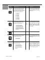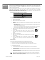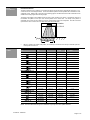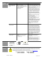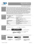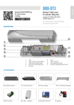
1
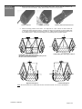
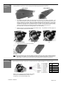
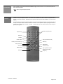
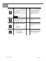
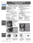
DK-12 USERS GUIDE OVERHEAD PRESENCE SENSOR PRODUCT DESCRIPTION The DK-12 (10DK-12) Presence Sensor is an overhead-mounted active infrared sensing device that provides detection for the triggering of automatic swing door safety functions. This sensor is designed for use with all of BEA’s LO-21 modules, as well as the MC-15. When used with BEA’s lockout devices, the sensor is programmed to allow two different fields of detection - one for detection when the door is in the fully closed position, and the other for detection when the door is fully open. As with all of BEA’s programmable sensing devices, full adjustability is achieved with the use of BEA’s hand-held remote control unit. This allows alteration of all of the available functions as well as for inquiry of existing settings. TECHNICAL SPECIFICATIONS DESCRIPTION Installation height Wide detection pattern Narrow detection pattern (center, left, right) Asymmetrical detection pattern (left, right) Mounting angle Power supply Frequency Consumption Output Max. voltage - relay contacts Max. current - relay contacts Max. Power supply Hold time Operating temperature Immunity Cable Weight Dimensions Material Housing color SPECIFICATION 6’ to 10’ 6’ W x 4’ D (see pattern chart) 2.5’ W x 3.5’ D (see pattern chart) 4’ W x 4’ D (see pattern chart) 20° - 26° - 32° 12 - 24 V AC or DC +/- 10 % 50 or 60 Hz 2W SPDT relay 60 V DC - 125 V AC 8 AMP - resistive 30 Watts (DC), 125 VA(AC) 1 to 10 seconds -30°F to 131°F Immune to electrical and radio frequency interference 3 feet of 6 conductor cable 1 lb., 11 oz. 11 ¼" L x 2¼" D x 3" H Aluminum & ABS plastic Black COMPONENT ID RIGHT ENDCAP MOUNTING BRACKET LEFT ENDCAP LED SAFETY PRECAUTIONS • • • • • • Shut off all power before attempting any wiring procedures. Maintain a clean & safe environment when working in public areas. Constantly be aware of pedestrian traffic around the door area. Always stop pedestrian traffic through the doorway when performing tests that may result in unexpected reactions by the door. Always check placement of all wiring before powering up to insure that moving door parts will not catch any wires and cause damage to equipment. Ensure compliance with all applicable safety standards (i.e. ANSI A156.10) upon completion of installation. 75.0082.05 20080125 Page 1 of 10 MECHANICAL INSTALLATION 1. Remove the left endcap by removing the two Phillips head screws. Use the Allen key provided in the screw kit to loosen the setscrew. Finally, slide the sensor from the mounting bracket. REMOVE ENDCAP 2. LOOSEN SETSCREW REMOVE SENSOR FROM BRACKET Select a mounting position for the sensor. For single door or a pair of doors, the sensor should be centered with relation to the door opening. If the DK-12 is used on any door with an opening greater than 6’, it is highly recommended to use more than one DK-12. Pattern selections will depend on the door and the mounting position. See the chart and diagram on the following pages for pattern selection. Double Swing Door (opening over 6’) See page 7 for selecting the pulsing frequency of two DK-12’s located next to each other Right Hand Swing Door Double Swing Door (opening less than 6’) Left Hand Swing Door NOTE: Be sure that there are no objects within the view of the sensor lenses, such as a door-operating arm. 75.0082.05 20080125 Page 2 of 10 MECHANICAL INSTALLATION (CON’T) The mounting bracket may be to a header or to the ceiling. Select the location for mounting, and secure solidly with screws provided. To mount the unit to the ceiling, the two plastic plugs will need to be removed. WALL MOUNT CEILING MOUNT 3. The installer must provide means for routing wires from the sensor to the inside of the header. The terminal block is located at the left end of the sensor. At the back edge of the left and right end covers, there is a small punch out slot to allow the concealed passage of wire into the sensor. A slot is also provided at the top of the sensor, should wires need to be routed from the opposite end of the sensor. Locate the wire passage hole on the header to keep it concealed. Once the hole is located and drilled, pull the 6-conductor wire from the header to the sensor, and leave a few inches hanging out. Do not drill holes in the aluminum-mounting bracket. (This voids warranty) 4. Slide the sensor into the mounting bracket at the desired angle. The greater the mounting angle, the further the pattern will be from the threshold. 20° (standard position) 5. 26° 32° Tighten the setscrew and replace the endcap. NOTE: BEA recommends the use of the WHU (weather protection hood) for any DK-12 that is installed outside and is exposed to direct weather. The circuit board of the DK-12 is not waterproof; therefore, it is susceptible to water damage. Any DK-12 that is returned due to water damage will be considered out of warranty. ELECTRICAL INSTALLATION At the left side of the sensor, remove the 7 pin terminal connector by pulling it straight out. Connect as shown: PIN WIRE COLOR 1 2 3 4 5 6 7 RED BLACK WHITE GREEN BROWN BLUE Refer to the wiring diagram in the respective User’s Guide for the type of Lockout Module being used (i.e. LO-21, LO-21U, MC-15, etc.) for all necessary wiring. 75.0082.05 20080125 Page 3 of 10 POWER-UP PROCEDURES Upon completion of mechanical and electrical installation, apply 12 to 24 V AC / DC +/- 10% to the DK-12, with the door in the closed position. NOTE: Refer to Programming/Set-up Section. REMOTE CONTROL All adjustments to the DK-12 will be made by BEA’s infrared (IR) remote control. The IR remote control enables the installer to set-up and adjust the detector. The remote uses a modified code, which makes it incompatible with the majority of consumer electronics. Because the end cap blocks the IR receiver after installation, no access code is required. To adjust the DK-12, stand to the left of the detector, aim the remote towards the left side of the detector (with the end cap removed) at a distance less than 6 feet from the DK-12. Each adjustment requires pushing two buttons on the remote; a ‘function’ button and then a number. Certain buttons are not used by the DK-12 and if they are pushed, will be ignored. Number Keys These 5 Keys Not Used Not Used Plus Key Check Values Unlock (not used on DK-12) Relay Hold Time Sensitivity Lock (not used on DK-12) Minus Key Relay Output Auto-Learn Time Pattern Width Not Used (Set up) Closed or Open Reset Factory Values Frequency 75.0082.05 20080125 Page 4 of 10 PROGRAMMING GUIDE KEY CHECK VALUES USER’S ACTIONS DEFAULT Press the function key that you desire to inquire about, followed by pressing the CHECK VALUES key. After pressing INQUIRY, count the number of LED flashes – this corresponds to the setting. LED STATUS After pressing a function button, the red LED flashes quickly. After pressing the CHECK VALUES key, the LED flashes the number of the current setting. No LED flash will indicate a setting of 0. EXAMPLE: 7 = Default sensitivity value SENSITIVITY SENSITIVITY alters the sensitivity of the IR field. Values range from 0 to 9, minimum to maximum respectively. Values can be programmed separately for door open and door closed position. RELAY HOLD TIME RELAY HOLD TIME refers to the hold time on the output relay of the DK-12. Values range from 0 to 9. Door closed=8 Door Open= 7 After pressing the SENSITIVITY key, the red LED flashes quickly. After pressing a number button, the red LED flashes slowly. 0 After pressing the RELAY HOLD TIME key, the red LED flashes quickly. After pressing a number button, the red LED flashes slowly. 2 After pressing the RELAY OUTPUT key, the red LED flashes quickly. After pressing a number button, the red LED flashes slowly. (Normally Open relay indicates relay closes upon detection, and is open upon a power loss). 0 = 1 second 9 = 10 seconds 1 second increments. RELAY OUTPUT The relay output has 4 possible values: 1 = Normally Closed Relay 2 = Normally Open Relay 3 = Continuous Detection 4 = Continuous Non-Detection 75.0082.05 20080125 Page 5 of 10 PROGRAMMING GUIDE – Cont. KEY AUTO-LEARN TIME USER’S ACTIONS The AUTO-LEARN TIME enables the DK12 to adapt to new permanent changes within its field of detection, after the set time (below) expires. Once expired, the DK-12 will return to a state of non-detection. DEFAULT LED STATUS 1 After pressing the AUTO-LEARN TIME key, the red LED flashes quickly. After pressing a number button, the red LED flashes slowly. Door closed=1 After pressing the PATTERN WIDTH key, the red LED flashes quickly. After pressing a number button, the red LED flashes slowly. After any pattern adjustment, simply launch another setup for the respective door position, using Magic Wand + 1 (door open) or 2 (door closed). 0= 30 seconds 1= 1 minute 2= 2 minutes 3= 3 minutes 4= 5 minutes 5= 7 minutes 6= 10 minutes 7= 15 minutes 8= 20 minutes 9= 25 minutes PATTERN WIDTH The PATTERN WIDTH refers to the width of the detection pattern. Patterns may be programmed independently for the ‘door open’ and ‘door closed’ positions. Door Open= 1 1= Wide Pattern (ABCD) 2= Wide Left Pattern (ABC) 3= Wide Right Pattern (BCD) 4= Narrow Left Pattern (AB) 5= Narrow Center Pattern (BC) 6= Narrow Right Pattern (CD) See Page 8 NOT USED FREQUENCY The FREQUENCY key allows for the change of operating frequency to reduce cross-talking between sensors. 1 After pressing the FREQUENCY key, the red LED flashes quickly. After pressing a number button, the red LED flashes slowly. 1= High Frequency 2= Low Frequency DEFAULT VALUES KEY (Magic Wand) The DEFAULT VALUES key is used to restore default values and is also used for launching a sensor set-up. 1= Door Closed Set-Up 2= Door Open Set-Up 3= Reset Factory Defaults (can be pressed while in door open or door closed position). 75.0082.05 20080125 N/A After pressing the DEFAULT VALUES key, the red LED flashes quickly. After pressing a number button, the sensor launches an immediate set-up as indicated by a flashing red LED. For values 1 & 2, the door must be positioned respectively so the sensor can learn the proper environment. Page 6 of 10 PROGRAMMING/ SETUP The DK-12 has been programmed with factory-default settings. They are defined on the chart on page 5 and 6. Please review the factory default settings before making any changes to the DK-12. If at any time the factory default settings are appropriate for your application, you DO NOT have to change them. Only change the parameters that are needed to customize your application. With the help of data wires from LO-21/SS-21, the DK-12 has the capability of having two different memory locations: DOOR OPEN and DOOR CLOSED. This feature enables the DK-12 to have different settings for the pattern selection and the sensitivity in both the DOOR OPEN and DOOR CLOSED positions. All the other settings of the DK-12 remain the same, independent of the position of the door. DOOR OPEN & DOOR CLOSED memory location capabilities: Dependent on door position Pattern selection Sensitivity Independent of door position Relay hold time Relay mode Auto learn time Frequency To program the DK-12, complete the following steps: 1. Review the default settings. 2. Determine which settings need to be changed. 3. Change any setting that is independent of the door position (relay hold time, relay mode, auto learn, frequency): • • • • Remove left end cap. Stand within 6’ of the left side of the sensor (do not be afraid to stand in the pattern area, but move out of the pattern after making a change). Point the remote control toward the opening (the receiver is located inside of DK-12 near terminal) Press the function button followed by the number that corresponds to the desired setting. 4. With the door in the CLOSED position, select the pattern size and the sensitivity setting desired. 5. Launch a DOOR CLOSED set-up with the remote: The LED will flash for approximately 10 sec. and stop once the set-up is complete (see set-up for more details). 6. Place the door into hold open. 7. With the door in the OPEN position, select the pattern size and the sensitivity setting desired. +1 8. +2 Launch a DOOR OPEN set-up with the remote: The LED will flash for approximately 10 sec. and stop once the set-up is complete (see set-up for more details). HELPFUL NOTES: Once a set-up is launched the LED will flash at 5 Hz for approximately 10 seconds. • If the set-up is successful, the LED will go off and the detector will function normally. • If the set-up is not successful, the LED will continue to flash, but at a lower frequency of 2.5 Hz. • Possible problems during setup: a. If a person walks through the detection zone during the set-up, the set-up can be disturbed. b. If a very reflective object is placed within 32 inches from the DK-12, it can blind the detector and make the set-up impossible. c. If the set-up that corresponds to the DOOR OPEN state is launched when the door is closed, the set-up will be ignored and vice versa. NOTE: 75.0082.05 20080125 When two DK-12’s are installed on the same door, place the end cap on one DK-12 and program the open DK-12. Once the first DK-12 is programmed, install its end cap and remove the second DK-12’s end cap and repeat the programming procedure. Page 7 of 10 SETUP INFORMATION PATTERN SELECTION The DK-12 detection zone is made up of 4 small zones placed next to each other, perpendicular to the door. The 4 zones are shown in the diagram below. There are 6 different patterns that are possible with combinations of the 4 detection zones. Please refer to the chart on the following page for the dimensions of the DK-12 detection zones at different mounting heights and mounting angles. The shape of the pattern can be different when the door is open and when it is closed. In the detector, there is no link between the pattern for the open door and the pattern for the closed door. The shape of the pattern is accessible as a function of door state and only the corresponding shape can be adjusted. The DK-12 receives input from the LO-21 or SS-21 as to the state of the door via the data lines. Header DK-12 Depth A B C D Width • PATTERN CHART After any change in the shape of the pattern, it is necessary to re-launch a new set-up for both the open and closed positions of the door. MOUNTING HEIGHT 7’3” ANGLE: 20° , #9 , #0 ANGLE: 26° , #9 , #0 ANGLE: 32° , #9 , #0 MOUNTING HEIGHT 8’3” ANGLE: 20° , #9 , #0 ANGLE: 26° , #9 , #0 ANGLE: 32° , #9 , #0 MOUNTING HEIGHT 9’6” Wide Pattern ABCD width x depth Narrow Pattern BC width x depth Narrow Pattern AB or CD width x depth Asymmetrical Pattern ABC or BCD width x depth 5’ x 3’3” 2’3” x 2’3” 2’6” x 3’ 3’6” x 3’3” 4’ x 2’6” 2’ x 2’ 2’ x 2’3” 2’3” x 2’ 5’ x 4’3” 2.3’ x 4’ 2’6” x 3’6” 4’ x 4’ 4’ x 3’3” 1’6” x 2’6” 2’ x 2’6” 3’ x 3’3” 6’ x 6’ 2’3” x 5’ 2’6” x 4’ 3’6” x 5’6” 3’6” x 4’3” 2’ x 4’ 2’ x 3’6” 2’3” x 4’ 5’3” x 3’6” 2’6” x 3’3” 2’6” x 3’ 3’6” x 3’6” 3’3” x 2’6” 2’ x 2’3” 2’ x 2’3” 2’3” x 2’6” 5’3” x 5’6” 2.3’ x 3’6” 2’3” x 3’3” 4’ x 3’6” 3’3” x 2’6” 1’3” x 2’3” 2’ x 2’3” 2’3” x 2’6” 5’6” x 6’9” 3’ x 6’ 3’3” x 5’6” 4’ x 6’9” 3’3” x 4’6” 1’6” x 4’ 1’6” x 4’ 3’ x 4’ 6’6” x 4’6” 2.3’ x 4’6” 2’3” x 4’3” 4’3” x 4’6” 4’ x 3’3” 1’6” x 3’3” 1’6” x 2’6” 2’3” x 3’ ANGLE: 20° , #9 , #0 ANGLE: 26° do not use ANGLE: 32° do not use NOTE: The above dimensions are given as references only! They are to aid in pattern selection. 75.0082.05 20080125 Page 8 of 10 TROUBLESHOOTING – PROBLEM PROBABLE CAUSE CORRECTIVE ACTION DK-12 will not set-up upon initial powering 1. 2. 3. 4. 1. Check terminals 1 & 2 for proper voltage 24 V AC/DC + 10%. 2. Make certain that the field of detection is all clear during the set-up and that all lenses are installed on the DK-12. If detection of movement is encountered upon initial setup, the DK-12 will continuously flash red at + 2 Hz. The DK-12 will also not set-up if permanent stationary objects are extremely close to the sensor. Ensure that, not only is the detection field all clear, but that the sensor is mounted properly (using the DK12 mounting block if necessary). If the mounting block is not used, and the backside of the sensor is less than 3” to the face of the door, it may be in saturation due to the door. Install the optional mounting block if necessary. 3. Ensure that all wiring connections have been properly made. Refer to wiring on Page 3. 4. Ensure that no problems exist with the lockout device or the lockout safety beams. DK-12 will not set-up after program changes have been made. 1. Door needs to complete one open – close cycle for DK-12 to learn both door positions. 1. Activate the door to allow a full open and close cycle. Allow the door to remain in the closed position to allow set-up. Activate the door open and allow the DK-12 to learn door open set-up. Normal operation should resume once both set-ups are complete. 2. Remove and re-apply power to the DK-12. Allow set-ups to complete for door open and door closed positions. Door will not open once setup has been completed. 1. DK-12 is in detection. 2. Improper wiring 3. Lockout safety beams are in detection 4. Improper relay output configuration 1. Check to ensure that there is no detection occurring at the DK-12. If the Red LED is on steady, there is detection. Make sure there have been no changes in the field of detection since set-up. If permanent changes have occurred, launch a new setup and re-test door. 2. Remove the output wires (common, normally open, normally closed) from the DK-12. CAUTION – there may possibly be no safety on the door when this test is performed. Activate the door control, if the door opens, the fault exists with DK-12 or related wiring. If door does not open, the faults may exist with the door control or it’s related wiring. 3. Disconnect the green & blue wires from the LO-21 to the door control safety and common terminals. If door opens when triggered, fault lies within the lockout safety beam set, or possibly with the LO-21. Refer to the LO-21 troubleshooting procedures in the respective manual. 4. Check to insure proper relay output setting. Refer to page 6. Typically, relay setting should be ‘Normally Open’. This means the relay would close upon detection. 75.0082.05 20080125 Improper input voltage DK-12 is in detection Improper wiring Problem may exist with safety beams or lockout relay. Page 9 of 10 TROUBLESHOOTING – Cont. PROBLEM PROBABLE CAUSE CORRECTIVE ACTION 1. DK-12 is in detection 2. DK-12 not recognizing door open position. Voltage or polarity of data wires may be incorrect 3. Faulty lockout relay 4. Faulty DK-12 1. If the Red LED is illuminated, launch a new set-up for the door-open position. If Red LED goes out after Set-Up, walk-test the pattern and tune if necessary. 2. If Red LED comes back on when door goes open after new set-up, the DK-12 may not be going into the door-open pattern. In the door open position, there should be approx. 12 volts DC on the data wires at the DK-12 terminal block. Without this voltage, the DK-12 will not go into a door open set-up. The polarity of these wires must also be correct. Terminal 6 is negative, terminal 7 is positive. 3. Ensure that lockout devices are powered and operating normally. 4. Check for proper polarity between lockout device and operator motor. 5. If no problems are apparent with lockout device, replace faulty DK-12. HELPFUL HINT: If the DK-12 will not enter into a door-open set-up, simply unlock the sensor with BEA’s remote control, and then force a door open set-up (see bottom of page7). If the red LED does not start flashing, voltage on the data wires is incorrect. Red LED flashes steadily at a rate of 2 Hz. 1. DK-12 is in detection during set-up. 1. If the DK-12 has tried to launch a new setup after the expiration of the Automatic Learn Time due to a permanent change in the field of detection, and there is continual movement in the field, the DK-12 will flash the Red Led indefinitely until movement has stopped. This may also occur if there is an object that is extremely close to the DK-12, thereby causing saturation. Once the object or movement has been eliminated, clear the field of detection. The DK-12 should set-up within 5 seconds and the Red LED should go out. Walk-test thereafter to ensure proper operation. DK-12 not reacting to the remote control 1. Batteries in the remote control are dead. 2. Distance between sensor and remote is too far. 1. Replace batteries in the remote control 2. Move in closer to the sensor when programming. Door will not close or DK12 will not inhibit during closing. HELPFUL HINT: Use BEA’s Spotfinder to test the output of the remote control. Simply point the remote at the IR Spot on the Spotfinder, press the Unlock key on the remote, and red LED should illuminate. ACCESSORIES Weather Hood Unit PN: 10WHU COMPANY CONTACT LO-21 Modules Microcell Safety Beams Do not leave problems unresolved. If a satisfactory solution cannot be achieved after troubleshooting a problem, please call BEA, Inc. If you must wait for the following workday to call BEA, leave the door inoperable until satisfactory repairs can be made. Never sacrifice the safe operation of the automatic door or gate for an incomplete solution. The following numbers can be called 24 hours a day, 7 days a week. For more information, visit www.beasensors.com. US and Canada: 1-866-249-7937 Canada: 1-866-836-1863 Northeast: 1-866-836-1863 75.0082.05 20080125 Southeast: 1-800-407-4545 Midwest: 1-888-308-8843 West: 1-888-419-2564 Page 10 of 10