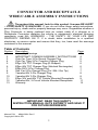
1
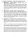
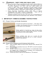
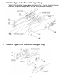
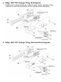
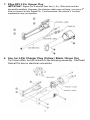
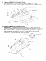
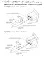
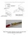
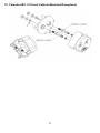
CONNECTOR AND RECEPTACLE WIRE/CABLE ASSEMBLY INSTRUCTIONS Throughout this manual, look for this symbol. It means BE ALERT – YOUR SAFETY IS INVOLVED. If you do not follow these safety instructions, personal injury, death and/or property damage may occur. Regardless whether a Plug Connector is being replaced onto an output cable of a charger or a Receptacle Connector replaces the vehicle or equipment’s electrical charging receptacle, read ALL WARNINGS – THE SAFETY OF YOUR LIFE AND PROPERTY DEPEND ON IT. If in doubt, defer installation to a qualified electrician, or service center and ensure that they, too, have read the warnings contained in this manual. Table of Contents Section 1 2 3 4 5 6 7 8 9 10 11 12 13 Description Page Assembly Warnings 2 IMPORTANT! COMMON ASSEMBLY INSTRUCTIONS 4 Club Car Type 3-Pin Round Charger Plug 5 Club Car Type 2-Pin Crowfoot Charger Plug 5 EZgo 36V TXT Charger Plug (D-Shaped) 6 EZgo 48V TXT Charger Plug (Notched Rectangular) 6 EZgo RXV 3-Pin Charger Plug 7 Star Car 3-Pin Charger Plug (Yel / Blk / Grn Tip) 7 Yamaha 48V 2-Pin Charger Plug 8 Yamaha 48V 3-Pin Charger Plug 8 EZgo 36V and 48V TXT Vehicle Mounted Receptacle 9 Yamaha 48V, 2-Circuit Vehicle Mounted Receptacle 11 Warranty 12 IMPORTANT: READ THIS SAFETY INSTRUCTION MANUAL IN ITS ENTIRETY AND SAVE IT FOR FUTURE REFERENCE Manual P/N: MNUL0021 Rev.5 Copyright © 2014 DPI 1 1. ASSEMBLY WARNINGS – READ THIS ENTIRE SECTION 1.1. 1.2. WARNING – INSPECT WIRING, CHARGER PLUGS, AND MATING VEHICLE RECEPTACLES Inspect all wiring for cracking, wear and tear and damage along Charger output leads to Plug and along Vehicle Receptacle to Battery Pack. Replace wiring (cabling) if required. Carefully inspect metal contacts of Charger Plug and Receptacle and replace if any pitting, dirt, or signs of wear and tear, including fatigued electrical contacts and tension springs are noticed or suspected. If a Charger Plug or Vehicle Receptacle is suspected of being three years or older, it is highly advisable to replace it with a new part! WARNING – PROPER CONNECTIONS MANDATORY! When connecting terminals to wires, it is imperative to BOTH crimp terminal onto wire and Solder terminal to wire. Also, solder all other mating parts of any mechanical connections, where such mating of parts, such as a ring terminal to a screw terminal, occurs. Over time these connections become loose causing heating, which can cause damage and promote liabilities beyond our control. CRIMPING AND SOLDERING ARE NOT OPTIONAL, BUT MANDATORY. Damage and liabilities caused by improper crimping and/or soldering of connections will not be warranted, nor supported by DPI. 1.3. WARNING – PROPER CIRCUIT FUSING MANDATORY! Regardless whether installation is a Plug Connector onto the output leads of a Charger or a Receptacle Connector onto a vehicle, inspect the wiring connection at the most positive battery terminal of the battery pack on the vehicle or equipment, and ensure that a fuse is installed at that terminal. The use of a circuit breaker or any circuit interrupting protection device that is more than 3 inches away from the positive battery terminal is ineffective. Refer to FIGURE-1 showing the proper placement of the fuse AT THE POSITIVE BATTERY PACK TERMINAL. Many Vehicle and Equipment Manufacturers failed to install protection at the POSITIVE battery terminal. Damage to wire insulation resulting from aging, environmental conditions such as ultraviolet light (sunlight), chemical abrasion, rodents, and other conditions can cause exposure of wire conductor to come in contact with other wire conductors and/or the chassis of the vehicle causing huge currents to flow from the battery pack that may result in personal injury, death and/or property damage. 2 In the event that fusing is absent – STOP INSTALLATION. Locate and purchase a 40Amp Fuse from many Automotive Retail sources, including DPI. Our inexpensive kit, P/N KITS0009, is readily available for purchase from our website, www.DPIpower.com, and will ensure protection from damaged battery wire cabling that could cause short circuits. Attach one end of fuse to the POSITIVE battery pack terminal and the other end of fuse to the cable ring terminal. Ensure all hardware connections are tight and use a lock washer. A nut and bolt connection, without the use of a lock washer will result in loosened connections causing personal injury and/or property damage. Figure 1- Fuse Installation at Positive Battery Pack Terminal WARNING – ENSURE PROPER CONNECTOR ASSEMBLY! 1.4. Pay attention to Polarity Markings on Connector Housings! Connector Pins and Sockets must be installed into their correct position in the Connector Housing as per the Positive and Negative markings found on the Plastic Connector Housings and matched in polarity and orientation to the Plug or the Receptacle into which they are expected to mate with. Verify proper seating of all contacts such as pins or sockets Ensure the Connector Plastic Housing parts mate together with all surfaces secured with no gaps produced. Secure fasteners, used in assembling housings, with adequate torque but do not over-tighten. Over-tightening these fasteners may produce distortions to the plastic housings. Before installing Receptacle Connectors, DISCONNECT CABLES FROM THE BATTERY PACK! 3 WARNING – VERIFY WIRE AND CABLE, USED 1.5. Every Connector Plug is manufactured with a built in Strain Relief on the back end of the Connector, where the cable enters the Connector Assembly. The Cable Type and Cable Gauge must conform to NEC Code for the application intended (battery charger for example), and is typically, minimally rated as a Hard-Usage, water and oil resistant, 12Ga wire or cable SJOOW, SJO, SJ type. Some Connector Assemblies require 10Ga Wire to secure mechanically with some crimped connections – these will be specified in the assembly on a per assembly build. Stripping Insulation from the end of the wire, prior to inserting into a terminal, requires that the strip length never exceeds ½ inch (12mm) 2. IMPORTANT! COMMON ASSEMBLY INSTRUCTIONS 2.1. Proper Crimp and Solder Examples Crimped and soldered connection – note shiny color of solder joint. Example shown for Yamaha Pin used in 2-Pin and 3-Pin Connector. Solder applied to terminal on crimp at wire entry, and also from ring to brass EZgo Terminal. All metal to metal joints have solder applied. Some contacts may rely on a screw for the mechanical fastening and not a crimp. However, solder is still required. 2.2. Proper Wire Stripping and Crimping Instructions 2.2.1. Strip insulation length off end of wire should never exceed 0.5in (12.5mm). 2.2.2. When stripping insulation from wire, DO NOT cut into the strands of copper wire. 2.2.3. Where a terminal uses a screw fastener to mechanically fasten the stripped wire, crimping is not necessary, but soldering the wire to the terminal is mandatory! 2.2.4. Soldering requires training and experience. This manual 4 3. Club Car Type 3-Pin Round Charger Plug ‘Inhibit Pin’ is also known as a ‘Lockout Pin’, and is used by many vehicles to prevent operation of the vehicle while charging. 4. Club Car Type 2-Pin Crowfoot Charger Plug 5 5. EZgo 36V TXT Charger Plug (D-Shaped) Inhibit wire is also known as ‘Lockout wire’ and is used by many vehicles to prevent operation of the vehicle while charging. 6. EZgo 48V TXT Charger Plug (Notched Rectangular) 6 7. EZgo RXV 3-Pin Charger Plug IMPORTANT: Signal Pin is shorter than the (+) & (-) Pins and must be rd physically installed. However, the charger cable may not have, nor use a 3 wire to connect to this Signal Pin. If unconnected, the vehicle’s ‘Lockout’ mechanism may not operate. 8. Star Car 3-Pin Charger Plug (Yellow / Black / Green Tip) Tip Colors differ, but all conform to the following assembly. The Dead Socket Pin has no electrical connection. 7 9. Yamaha 48V 2-Pin Charger Plug Use of a Crimping Tool is required and available from DPI purchased separately. Contact DPI for Part Number and Purchase. 10. Yamaha 48V 3-Pin Charger Plug IMPORTANT: Signal Pin is shorter than the (+) & (-) Pins and must be rd physically installed. However, the charger cable may not have, nor use a 3 wire to connect to this Signal Pin. If unconnected, the vehicle’s ‘Lockout’ mechanism may not operate. Use of a Crimping Tool is required. Contact DPI for Part Number and Purchase. 8 11. EZgo 36V and 48V TXT Vehicle Mounted Receptacle A Low-Cost Anderson Hand Tool (p/n 1309G4) Crimp Die Set Tool is available from DPI - purchased separately. Contact DPI for purchase. 36V TXT Receptacle - Refer to Illustration. 48V TXT Receptacle - Refer to Illustration: 9 EZgo Socket Contact - Example of a proper crimp and solder joint from 10ga wire to socket contact 10 12. Yamaha 48V, 2-Circuit Vehicle Mounted Receptacle 11 13. LIMITED WARRANTY Diversified Power International LLC (DPI) warrants exclusively to the original purchaser that this product will be replaced or repaired, at DPI’s option, if it fails during the first year after date of purchase due to defect in material or workmanship. Proof of purchase is required for all claims. This warranty does not cover failures arising out of improper use, maintenance or operation of the product, nor does it cover failures arising from improper soldering or crimping of wire terminals/pins. Repair or replacement as provided under this warranty is the exclusive remedy of the consumer. DPI shall not be liable for any incidental or consequential damages for breach of any expressed or implied warranty on this product. Except to the extent provided by applicable law, any implied warranty of merchantability or fitness for a particular purpose on this product is limited in duration to the duration of this warranty. Some states do not allow the exclusion of limitation of incidental or consequential damages, or allow limitations on how long an implied warranty lasts, so the above limitations or exclusions may not apply to you. This limited warranty gives you specific legal rights and you may also have other rights which vary from state to state. Contact Information: DIVERSIFIED POWER INTERNATIONAL LLC 423-538-9002 www.DPIpower.com Return information: DIVERSIFIED POWER INTERNATIONAL LLC 414 CENTURY COURT PINEY FLATS, TN 37686, U.S.A. 423 538-9002 RMA # ________________ For further information, product updates, technical information, or general inquiries, also, please visit our web site at: www.DPIpower.com 12