1
DV2000 Digital Video
VBI Encoder / Character Generator
USER'S MANUAL
For Software Revision: 2.32
ULTECH Corporation
28 Great Hill Road, Bldg. #C, Seymour, CT 06483, USA
TEL: (203) 735-5805, FAX: (203) 735-6653, WEB: www.ultechvideo.com
WARRANTY
This product is warranted against defects in material and workmanship for a period of one year from date of shipment. During the
warranty period, ULTECH Corporation will, at its option, either
repair or replace defective products. For warranty service or repair,
this product must be returned to a service facility designated by
ULTECH Corp. Buyer shall prepay shipping charges for products
returned to ULTECH for warranty service; ULTECH shall pay
shipping charges to return product to the Buyer. Buyer shall pay all
shipping charges, duties, and taxes for products returned to ULTECH from countries outside of the USA.
LIMITATION OF WARRANTY
The foregoing warranty shall not apply to defects resulting from
improper use by Buyer. No other warranty is expressed or implied.
ULTECH specifically disclaims the implied warranties of merchantability and fitness for a particular purpose. ULTECH shall not be
liable for any direct, indirect, incidental or consequential damages
resulting from the use of this product.
IMPORTANT
This instrument is an AC mains-operated electrical apparatus.
Maintenance, repairs, and adjustments must be carried out only by
qualified personnel. Do not operate the unit without the covers in
place.
© ULTECH Corporation 1999
All rights reserved. Reproduction in any form is not permitted without written authority from the copyright owner.
Manual Publication No. PB100-DV2000, Rev. January 15, 1999
Printed in USA
Contents
1. General Information ...................................................................................... 5
1.1 Introduction .................................................................................................................................................................... 5
1.2 Closed Caption Encoder ................................................................................................................................................. 6
1.3 Character Generator ........................................................................................................................................................ 7
2. Installation .................................................................................................... 9
2.1 How to connect ............................................................................................................................................................... 9
3. Operating Instructions ................................................................................ 11
3.1 Front panel controls, indicators ..................................................................................................................................... 11
3.2 Rear panel connections ................................................................................................................................................. 12
3.3 Operating the DV2000 ................................................................................................................................................. 15
4. Front Panel Menus ..................................................................................... 17
4.1 Main Menu ...................................................................................................................................................................
4.2 Job Menu ......................................................................................................................................................................
4.3 CC Monitor Setup Menu ..............................................................................................................................................
4.4 Time Code Offset Menu ...............................................................................................................................................
4.5 Com 1 Setup Menu .......................................................................................................................................................
4.6 Safe Title Area Menu ....................................................................................................................................................
4.7 CC Level Setup Menu ..................................................................................................................................................
4.8 CC Waveform Position Menu .......................................................................................................................................
4.9 EDH Error Detecting and Handling Status Menu ........................................................................................................
4.10 EDH Setup Menu ........................................................................................................................................................
17
18
19
19
20
21
22
23
24
25
5. Script, Caption, and Subtitle Files .............................................................. 27
5.1 Introduction ..................................................................................................................................................................
5.2 Script Files ....................................................................................................................................................................
5.2 Caption Files .................................................................................................................................................................
5.3 Subtitle Files .................................................................................................................................................................
5.4 Graphics Files ...............................................................................................................................................................
5.5 UYC File Format ..........................................................................................................................................................
27
27
30
31
32
34
6. Technical Reference ................................................................................... 41
6.1 Calibration ....................................................................................................................................................................
6.2 Pinouts ..........................................................................................................................................................................
6.3 Disk Contents ...............................................................................................................................................................
6.4 Specifications ...............................................................................................................................................................
41
42
44
45
4
ULTECH DV2000 User’s Manual
1. General Information
5
1. General Information
1.1 Introduction
Thank you for purchasing the DV2000—a versatile digital video platform for closed caption,
text, and graphics generation. DV2000 is the industry’s first closed caption encoder and
subtitle generator combined in a single unit. With it you can generate slates, bugs, TV rating
icons and subtitles while encoding closed caption and XDS data. Post production and tape
duplication facilities can perform these jobs in a single pass. Broadcasters can comply to
FCC rules with a single unit by encoding closed captions and “V-chip” data while simultaneously displaying on-screen TV rating icons.
DV2000 is constructed in a modular fashion. All of the major components plug into industry
standard slots. The modular architecture allows for easy repairs and upgrades in the field.
There are slots available for options or for other functions that our industry may require in
the future.
Easy Operation
A common complaint in the caption industry is that post houses and tape duplicators must
deal with caption files with different formats and encoding requirements. DV2000 addresses
this by reading all of the popular caption file formats. The encoder automatically determines
the proper settings by looking at the data contained in the file—the operator doesn’t even
have to specify the format.
DV2000 can read individual caption files, or it can read script files. A script file may contain
instructions to display slates, logos, icons, etc. and it may also start a caption encoding
session. Caption agencies may prepare script files that perform special tasks. Script files can
automatically set DV2000 to the proper configuration to perform an encoding or subtitling
job. ULTECH provides script templates which make it easy for caption agencies or supervisors to create custom scripts.
In a broadcast environment, DV2000 can act as a caption server. Caption data does not have
to reside in the VBI of programs on videotape; it can be encoded “on-the-fly” as the program
airs. Captions may be downloaded to DV2000’s hard disk via network or modem interface.
A play list may be generated that instructs DV2000 to encode a sequence of shows based on
time code. This technique saves a tape generation, plus it allows easier reformatting of
captions if a show is edited.
6
ULTECH DV2000 User’s Manual
1.2 Closed Caption Encoder
Caption encoding is where DV2000 truly excels. The heart of the encoder is the CCX
caption encoding software module. CCX is ULTECH’s PC-based closed caption encoding
program. This program has been in use during the last three years in dozens of post production and duplication facilities. CCX has evolved into a stable and highly accurate method for
metering captions based on time code. It ensures that captions will be revealed on the
viewer’s screen at exactly the moment intended by the caption’s creator. We’ve taken our
time-tested CCX software and modified it for use in the DV2000.
DV2000’s most important feature is its ability to read caption files from the industry’s
leading agencies and caption software providers. Files from unsupported software venders
may be converted to ULTECH .ULT format and read directly. Of course, DV2000 may still
encode captions the old fashion way—by sending data to a DV2000 serial port from a PC.
DV2000 can encode on any VBI line, in component or composite format, in NTSC or PAL.
It can encode field 2 XDS data such as “V-chip” data while encoding captions in field 1.
DV2000 has an upstream digital caption decoder, so it can reencode, pass, or merge data per
EIA-608 recommendations. All of DV2000’s encoding functions are performed in softwaresoftware that can be upgraded via ULTECH’s web site. This ensures that DV2000 will stay
current no matter what the industry may conjure up. Even DV2000’s waveform generator is
controlled via software. A benefit of this is that the caption waveform’s “0 IRE” level and its
“50 IRE” level may be set from the front panel or via script commands—no more problems
with VTR’s and converters that strip or add NTSC setup levels.
1. General Information
7
1.3 Character Generator
You may purchase DV2000 with an optional character generator to produce text and graphics on-screen. The CG option consists of a 2.5 GByte hard drive, 120 MByte LS-120
SuperDrive, 16 MByte video RAM module, faster CPU, and associated software. The CG
provides two video frame stores of 24 bit RGB plus 8 bits of transparency (“alpha” channel).
You can create any image in 16 million colors with 256 levels of transparency over the
background video. Your image can occupy up to 512 TV scan lines in each frame. Although
the DV2000 is not intended for special effects, it is possible to create simple animations with
smooth motion—a rotating globe or a logo that grows, for example. A global fade function
allows you to fade images on and off the screen independently from transparency settings.
How to create images with DV2000 CG
The DV2000 CG can display text and graphics based on low level “drawing” commands (the
traditional method), or it can display text and graphics as individual “subpictures” (the
modern method). In both cases, the commands and/or subpictures are received via a communications port, network interface, or local script file residing on disk. Commands and
subpictures can be displayed by DV2000 based on longitudinal time code, GPI triggers, and
internal or external timing.
In drawing mode, DV2000 provides the same commands found on ULTECH’s SG401
Subtitle/Character Generator. This mode is useful for repetitive display of text such as
subtitling. Characters are rendered within the DV2000 in the specified font with the specified effects. In drawing mode, DV2000 uses the Unicode character set together with
TrueType fonts. TrueType fonts may be downloaded through any communications port, or
may be installed via disk. Version 2.26 Note: SG401 backward compatibility
In subpicture mode, DV2000 can display graphics images that are in .BMP, .PCX, .TIF, and
.PNG formats. Subpictures are loaded into a non-displayed graphics buffer then displayed at
the desired time. Subpictures are always rendered off-line, that is, on an external PC, Mac, or
workstation. You can use any graphics drawing program to create subpictures including
those from Adobe, Macromedia, MetaCreations, and many others. Subpictures can be wiped
or faded on and off the screen.
Animation is accomplished by creating a series of individual frames—perhaps dozens—that
represent the desired motion. The frames are downloaded to DV2000’s hard drive via a
network interface or 120 MByte SuperDrive, then played in sequence. Animation packages
such as MetaCreation’s Bryce3D render individual frames from key frames automatically.
8
ULTECH DV2000 User’s Manual
2. Installation
9
2. Installation
2.1 How to connect
1. Apply source serial digital video to VIDEO IN connector. Source must be standard
SMPTE 259M video. The DV2000 terminates the source video with 75 ohms.
2. Take the program video with encoded data/text & graphics from VIDEO OUT #1 or
VIDEO OUT #2. VIDEO OUT #1 and #2 are serial digital outputs.
3. Connect VIDEO OUT #1 or #2 to Monitor Video In, a serial digital input.
4. Connect an analog composite video monitor to MONITOR VIDEO OUT or an S-video
monitor to Y/C OUT (an S-video monitor is preferred). This output is used to monitor
closed captions and to display on-screen menus when the DV2000 is in setup mode. This
output is not intended to be used as a source of analog program video. If you need analog
program video, it is recommended that you use a high quality serial digital-to-analog
video converter at one of the DV2000 program video outputs.
5. Connect longitudinal time code to the LTC In connector via an XLR-to-Mini-DIN time
code adapter cable (ULTECH part number OPT14). The LTC input can use either balanced or single-ended time code with a nominal level of +4 dBu.
6. Apply AC line power to the unit via the detachable three wire cord.
Grounding (earthing)
The DV2000 must be connected to a protective earth conductor via the three wire AC line
(mains) cord. The AC power plug shall be inserted only into a receptacle outlet that has a
protective earth contact. The ground wire must not be defeated by use of a two wire extension cord.
!
s
WARNING: Any interruption of the power line ground circuit inside or
outside the DV2000, or removal of the AC receptacle ground
wire, will create a potential shock hazard.
10
ULTECH DV2000 User’s Manual
3. Operating Instructions
11
3. Operating Instructions
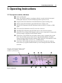
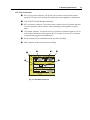
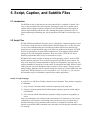
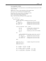
3.1 Front panel controls, indicators
➊
➋
Power on/off switch.
➌
➍
➎
Program Video LED. Illuminates when DV2000 detects proper incoming video.
➏
➐
➑
Time code LED. Illuminates when LTC time code is detected.
➒
Floppy Drive. The DV2000 can read caption, subtitle, script, or graphics files via this
drive. Also, DV2000 system software may be upgraded from this drive. DV2000’s
equipped with the optional character generator come with an LS-120 SuperDrive which
can read 120 MByte disks as well as 3 ½” 1.44 MByte disks.
➓
Cursor keys. Press ENTER to bring-up the on-screen menu. Press the left, right, up,
down cursor keys together with the ENTER key to move through the menus and make
selections.
Reset. The DV2000 contains a reset button which is recessed inside the front panel.
Pushing this button will cause the DV2000 to perform a power-on reset.
Monitor Video LED. Illuminates when DV2000 detects monitor video.
Data In LED. Illuminates when DV2000 detects data at its RS-232, modem, or USB
inputs.
Hard Disk LED. Illuminates when DV2000 reads or writes from its hard drive.
Setup LED. The red Setup LED illuminates when you are in setup mode. In setup mode,
on-screen menus are displayed on the decoder monitor.
Filter grill. The filter element should be washed
or replaced every six months—sooner if your
installation is particularly dusty.
➌
➊
➋
Fig. 3-1. Front panel
➎
➍
➐
➏
➒
➑
➓
12
ULTECH DV2000 User’s Manual
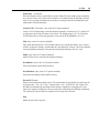
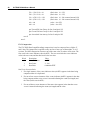
3.2 Rear panel connections
➊
Fan Grill. You must mount the DV2000 in a location that provides at least 6” of clearance behind this grill. Air is supplied through the front panel filter and discharged
through the rear panel fan grill.
➋
IEC power output connector for detachable three wire AC line cord. Rated 120 VAC at
3A Max, or 240V at 2A Max.
➌
IEC power input connector for detachable three wire AC line cord.
➍
120 VAC / 240 VAC line voltage selection switch.
➊
➋
➍
CPU / Data
Keyboard
(Not Required)
Com
Port 1
Mouse
(Not Required)
Video / Control
VGA Out
(Not Required)
Y/C
Out
GPI In/Out
Video
Out
Monitor
Video In
CPU
Interface
OSD/CC
Decoder
1
AC Out
120 VAC
GND
LTC In
240 VAC
2
(Analog)
(Digital)
Video Out Video Out
#2
#1
Video In
Serial
Digital
Interface
Network
Interface
AC In
USB
#1
USB
#2
Com
Port 2
Additional
Ports
(Spare Slot)
optional
Fig. 3-2. Rear panel
➌
optional
3. Operating Instructions
13
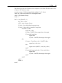
CPU / Data Connections
➊
PS-2 style keyboard connector. You do not need to connect a keyboard for normal
operation. You only need a keyboard for performing system upgrades or maintenance.
➋
Com 1 RS-232 serial interface connector.
➌
PS-2 style mouse connector. You do not need to connect a mouse for normal operation.
You may optionally connect a mouse when performing system upgrades or maintenance.
➍
VGA output connector. You do not need a VGA monitor for normal operation. All onscreen menus and status screens appear at the VGA output. You need a VGA monitor
when performing upgrades and maintenance.
➎
RJ-45 modular jack for unshielded twisted pair network cabling.
➏
BNC connector for thin coaxial network cabling.
➋
➊
Keyboard
(Not Required)
➎
➌
Com
Port 1
Mouse
(Not Required)
➍
VGA Out
(Not Required)
CPU
Interface
➏
Network
Interface
USB
#1
USB
#2
Additional
Ports
optional
Fig. 3-3. CPU / Data connections
Com
Port 2
14
ULTECH DV2000 User’s Manual
Video / Control Connections
➊
Serial digital video input. This input expects a standard SMPTE-259M component
digital or composite digital signal, in either 525 or 625 standard. The input is internally
terminated by 75 ohms.
➋
Serial digital program video output #1. This is a standard SMPTE-259M output with a
75 ohm source impedance. The output employs a controlled risetime cable driver
circuit.
➌
Serial digital program video output #2. Identical to program video output #1.
➍
LTC time code input. This is a balanced longitudinal time code input that expects a
nominal +4 dBu analog signal. A mini-DIN connector is used to save panel space.
ULTECH option OPT 14 can adapt the LTC connector for use with a male XLR plug.
➎
Monitor video input. This is a SMPTE-259M serial digital video input that provides
caption monitoring and on-screen menus. This input may be connected to DV2000
program video output #1 or #2, either through a short cable or via a serial digital router.
Using a router gives you the option of monitoring closed captions from other serial
digital video devices, such as a VTR. The input is terminated with 75 ohms.
➏
Monitor video output. This is a 1Vpp analog composite video output with a 75 ohm
source impedance. This output contains an analog version of the program video with
Captions/Text/XDS and CG overlaid. Also, the on-screen menus appear on this output
as well. You can turn off caption monitoring as well as the on-screen menus. This
output is not intended to be used as a high quality analog program output.
➐
Y/C monitor video output. This is an analog S-video output that delivers an analog
version of the program video with captions, CG and on-screen menus overlaid.
➑
GPI port. This is a dual bidirectional GPI port. You can receive GPI triggers from
external equipment, or you can program the DV2000 to generate GPI triggers and
events. You respond to GPI triggers from within a program script. Likewise, you can
generate GPI triggers from a script, perhaps based on certain time codes.
➑
➐
➏
Y/C
Out
GPI In/Out
Video
Out
➎
Monitor
Video In
OSD/CC
Decoder
1
GND
2
LTC In
(Analog)
(Digital)
Video Out Video Out
#2
#1
Video In
Serial
Digital
Interface
(Spare Slot)
➍
➌
➋
➊
Fig. 3-4. Video / Control connections
3. Operating Instructions
15
3.3 Operating the DV2000
Power on
When power is first applied, the DV2000 will boot its operating system and will then run its
DV2000 application program. This process takes about 15 seconds. After the application
program has started, a DV2000 status screen will appear at the VGA output; nothing appears
at the monitor output other than the video source which is connected to the monitor input.
Menus / cursor keys
Front panel control of the DV2000 is accomplished using the cursor keys and on-screen
menus. The menus appear at the monitor output BNC and/or the VGA output. Pressing
ENTER brings-up the main menu. Pressing the left and right arrow keys brings you to other
menus. Pressing the up and down arrow keys allows you to scroll through choices within a
menu. Pressing ENTER within a menu allows you to make changes to settings. Every menu
screen has help messages to guide you.
Settings
Many aspects of the DV2000 may be customized by way of user settings. One example of a
setting is closed caption waveform amplitude—the user has the ability to set the waveform to
compensate for video sources that may, or may not, have 7.5 IRE pedestals added. Settings
are made from the front panel, or they may be done via a script file, network, or serial port.
Settings made from script files are active only while the script file is running. When the
script finishes, settings revert back to the previous settings: the ones set from the front panel,
network, or communications port. Settings may be “locked-out” from certain sources. For
example, you may prevent the closed caption line to be changed from any source other than
the front panel. You enable or disable settings in a command acceptance table that is accessed from the front panel.
The DV2000 stores all current settings on its hard drive in a file called “settings.cfg”. To
restore factory default settings, simply delete or rename this file.
Over Temperature Alarm
DV2000 contains an over temperature alarm that produces a continuous beeping if the
internal processor overheats. This could be caused by a dirty filter element, restricted air
flow, or fan failure. Operating DV2000 in an over-temperature condition will result in erratic
operation.
16
ULTECH DV2000 User’s Manual
4. Front Panel Operation, Menus
17
4. Front Panel Menus
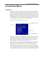
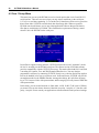
4.1 Main Menu
DV2000 users typically deal with “jobs”, so the DV2000 menuing system is designed to
handle jobs. A job may be a closed caption encoding session, or it may be a subtitle mastering session. Jobs are more natural for post production users than broadcast users. In post
production, the DV2000 is used exclusively on a job by job basis. For example, in one day, a
tape duplicator may encode closed captions for two movies, and create subtitles for a third.
Each of these activities is considered a separate job. Broadcasters, on the other hand, may
use the DV2000 for real-time closed caption encoding only. In that case, they may only have
one “job” configured, and it may be named “Live Closed Captioning”.
The main menu is also referred to as the “jobs list” menu.
DV2000 software revision
Job list
Job status
TV standard detected
DV2000 has two “built-in” jobs: Load Job From Floppy and Load Job From Server. Other
jobs that appear on the jobs menu are loaded by the user. When Load Job From Floppy is
selected, files from a floppy disk (or 120 MByte SuperDisk) are copied into a unique
subdirectory under the “jobs” directory on the DV2000 hard drive. Only script, caption,
subtitle, and graphics files are copied; all other files are ignored.
If the job consists of a single caption file when loaded, the menu changes to that specific
caption job and the job is run automatically. This means an operator has only to insert a
floppy disk into the drive and select Load Job From Floppy to run an encoding job.
The DV2000 allows you to change certain parameters associated with closed captioning,
such as waveform amplitude and time code offset. When a caption job is run as described
above, the front panel settings are in effect. A user may create a script file that changes some
of the settings, then executes the caption job. In that case, the script file settings are used.
18
ULTECH DV2000 User’s Manual
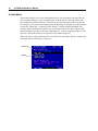
4.2 Job Menu
The job menu allows you to work with a particular job. You can run the job, cancel the job
(if it is already running), save it as another name, or delete the job. Each job resides in its
own subdirectory under dv2000\jobs. The directory has the same name as the main job file.
For example, if you load a closed caption job from the floppy or network server that contains
a single file “Blinky.cap”, a directory called “Blinky” is made: dv2000\jobs\Blinky. The
directory Blinky contains the file Blinky.cap. If you load a subtitle file called “Movie1.usf”
and associated bit map files, a directory called “Movie1” is made: dv2000\jobs\Movie1. The
directory contains the file Movie1.usf plus all of the subtitle image files.
When you delete a job from the hard drive, all of the files contained in the job’s subdirectory
are erased, and the subdirectory is removed.
Name of job
Options
4. Front Panel Operation, Menus
19
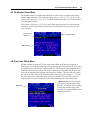
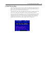
4.3 CC Monitor Setup Menu
The monitor menu lets you determine which line 21 data service to monitor at the analog
monitor output connector. You can choose field 1 services: CC1, CC2, T1, T2, or you can
choose field 2 services: CC3, CC4, T3, T4, XDS (Extended Data Services). Press ENTER to
cycle through the choices.
TIP: Choose a Text service (T1-T3) as a quick check for the presence of a closed caption
waveform—you will get a black box that nearly fills the monitor screen if a line 21 waveform is present.
Line 21 service
monitored
Navigation help
Help messages
4.4 Time Code Offset Menu
DV2000 contains an internal LTC time code reader. When an off-line closed caption or
subtitle job is run, captions/subtitles are processed when time code read from the LTC input
port matches time code from the caption/subtitle file. The timing for caption/subtitle files is
established from the time code provided to the caption agency. But when the job is run, the
time code accompanying the program video may have changed. The time code offset menu
lets you adjust time code read by the internal time code reader in increments of +/- 1 frame.
The time code offset is added to the time read by the internal LTC reader. The time code
displayed in the on-screen menu reflects the sum of incoming time code and the offset.
Menu name
Important Note: Caption creators
go to extreme lengths when timing
captions. You should discuss changes
in time code with the agency that
provided the captions/subtitles before
offsetting time code.
20
ULTECH DV2000 User’s Manual
4.5 Com 1 Setup Menu
This menu lets you set-up the DV2000 to receive closed caption data via its Com1 RS-232
serial interface. There are two cases where you may want to send data via the serial port:
1). For live or real-time captioning, 2). To encode line 21 data from off-line service providers
that will not allow ULTECH to encode their data from floppy disk. Wherever possible,
DV2000 users should choose service providers/applications software that provide data as
files that are read directly by DV2000. This eliminates the requirement of having a standalone PC drive the DV2000 via the serial port.
In an effort to support existing software, ULTECH will provide several “emulation” modes
for line 21 encoding via the DV2000 serial port. The current version of DV2000 software
provides compatibility with the ULTECH Insertacap. This mode offers both field 1 and field
2 encoding for Captions, Text, and XDS Extended Data Services. You may obtain a
programmer’s reference by contacting ULTECH. Nearly every real-time and off-line application can be handled in Insertacap emulation mode. In the near future, ULTECH will provide
an emulation mode for the EDS400 Encoder. Among other things, this will allow the merging of TV Crossover Links with upstream data, and the merging of locally inserted XDS data
with upstream data.
In this menu, you can set the baud rate to 1200, 9600, 19.2K, 38.4K, 57.6K, and 115.2K bits
per second. You can also choose between 8 data bits, no parity, 1 stop bit, or 7 data bits, odd
parity, 1 stop bit. Please consult your applications software manual for the preferred settings.
4. Front Panel Operation, Menus
4.6 Safe Title Area Menu
This feature displays a safe title area test pattern per SMPTE Recommended Practice
RP 27.3-1989. The DV2000-generated pattern deviates from the SMPTE pattern in
that it shows square corners as well as round corners.
The pattern will “paint” after each subtitle when used with .usf subtitle scripts. This
allows you to easily check each subtitle in a show for conformance to RP 27.3.
You can set the safe title area pattern to several colors and transparencies by cycling
through the color menu. ULTECH also provides a useful graticule for taking measurements of on-screen items in terms of DV2000 coordinates. The graticule is a
graphics file called TestGrid.uyc and a related script file: TestGrid.scr.
21
22
ULTECH DV2000 User’s Manual
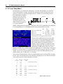
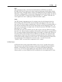
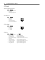
4.7 CC Level Setup Menu
DV2000 allows you to adjust the “data bit low” level and “data bit high” level of the encoded closed caption waveform. Normally, the adjustment is made such that data bit low
produces a 0 IRE level, and data bit high produces a 50 IRE level. In an analog encoder,
these adjustments are usually
made with a trim pot. In the
Data Bit High
DV2000 digital encoder, the
adjustments are made by
specifying a numeric value,
Data Bit Low
either from the front panel or
via a script command.
SMPTE 125M specifies the assignment of luminance values as 877 quantization levels with black
level corresponding to level 64 and the peak white level corresponding to level 940.
Reserved to indicate TRS
Black Level
White Level
Reserved to indicate TRS
IRE
7.5
100
-
10 bit
8 bit *
0 (000H)
0 (00H)
64 (040H)
16 (10H)
940 (3ACH) 235 (EBH)
1023 (3FFH) 255 (FFH)
* The DV2000 waveform generator uses 8 bit values
The spec fails to address the levels used by VBI
services such as Closed Captioning and NABTS
teletext which are referenced to blanking level (0
IRE). So the industry has responded with two
solutions. The first solution is to change the slope
of the DAC during the VBI so that the value of 16
corresponds to 0 IRE and the value of 235 corresponds to 100 IRE. This is usually termed “no 7.5 IRE setup” or “without setup”. The second
solution is to use the values 1-15 to generate the IRE values below the value of 16 (7.5 IRE).
An IRE value of zero is not possible because zero is reserved for TRS indication. This is
usually termed “with 7.5 IRE setup” or “with setup”.
The existence of both solutions in the field complicates the task of inserting VBI waveforms
into D1 video. The DV2000 solves this problem by allowing the user to set the min and max
values used to generate closed captioning waveforms.
8 bit
D1 value
IRE with
setup
IRE without
setup
1
2
3
1.16
1.59
2.01
-
15
16
17
7.08
7.50
7.92
0.00
0.46
ï nominal min w/o setup
116
117
118
49.74
50.16
50.58
45.66
46.12
46.58
ï nominal max with setup
125
126
127
53.54
53.96
54.38
49.77
50.22
50.68
ï nominal max w/o setup
235
100.00
100.00
ï nominal min with setup
Table 4.1 IRE vs. D1 Level
4. Front Panel Operation, Menus
23
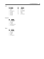
4.8 CC Waveform Position Menu
DV2000 allows you to adjust the location of the closed caption waveform with respect to the
timing reference code embedded in line 21. The factory default positions the waveform in
exactly the correct location per the recommended practice. In general, you should never set
the waveform position to anything other than
the factory default. However, there may be one
case where you need to adjust the timing of the
line 21 waveform: some digital component
video-to-analog video converters insert the
reconstructed horizontal interval in an arbitrary
location with respect to the embedded timing
reference codes. If you are using such a
converter to derive analog video from the
DV2000 program outputs, you may need to
adjust the timing of the line 21 waveform.
24
ULTECH DV2000 User’s Manual
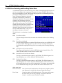
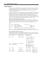
4.9 EDH Error Detecting and Handling Status Menu
A recommended practice exists that allows you to detect serial digital transmission errors as
well as errors in digital video equipment. The practice is known as SMPTE RP 165 Error
Detection and Handling System. The DV2000 fully supports this recommended practice by
providing two EDH processors: one to detect
errors in upstream equipment, and one to
recompute checksums for the benefit of
downstream equipment. The system works by
computing and transmitting checksums
separately for full field data, for active picture
data, and for ancillary data. The DV2000
computes the checksum for the incoming data
and compares it against the transmitted
checksum. If they deviate then an error flag is
set in the EDH Status Menu. A flag is set
according to the nature of the error.
The following is an explanation of possible
errors:
EDH
Error Detected Here
If the incoming checkword does not match the calculated checkword, the EDH flag
is set.
EDA
Error Detected Already
If the incoming EDH flag is set and the EDA flag has not been set, the EDH flag will
be cleared and the EDA flag will be set. However, if the incoming checkword is
invalid then the outgoing EDA flag will be set according to the incoming EDA flag
only.
IDH
Internal Device Error Detected Here
These flags would normally be set by the DV2000 to detect internal failures. The
current DV2000 software version does not set these flags.
IDA
Internal Device Error Detected Already
This flag is passed from input to output by the DV2000. The DV2000 ignores this
flag, although you can view the flag in the EDS Status Menu.
UES
Unknown Error Status
This flag is passed from input to output by the DV2000. The DV2000 ignores this
flag, although you can view the flag in the EDS Status Menu. This bit is also set if
the incoming data does not have an error data packet. This informs downstream SDI
devices that the data being sent by the DV2000 has not been checked for errors.
Other menu items:
Packet Checksum
This is the latest full field checksum. The checksum, together with the
error flags may be refreshed by selecting “Update Error Status”.
Error Count
Counts the number of fields that had errors. This counter will accumulate errors until you reset it by selecting “Clear Errors and Error
Counter”, or until a count of 2 million is reached.
4. Front Panel Operation, Menus
25
4.10 EDH Setup Menu
This menu allows you to ignore certain error conditions described for the previous menu.
When disabled, an error of this type will not increment the Error Count. When disabled, the
corresponding flag in the EDH Status Menu is displayed as a dash.
26
ULTECH DV2000 User’s Manual
27
5. Script, Caption, and Subtitle Files
5.1 Introduction
The DV2000 is able to read and encode closed caption files in a number of formats. Likewise, it can read subtitle files and associated “bit mapped” image files to produce open
subtitles. When reading a caption or subtitle file, the DV2000 processes each caption or
subtitle single-mindedly until the file ends. Although this mode of operation is fine for
simple captioning and subtitling jobs, the full potential of DV2000 is realized using script
files.
5.2 Script Files
DV2000 VBI Encoder/Subtitle Generator may be controlled by command sequences stored
in script files. Script files may be loaded from the DV2000 floppy drive, or they may enter
via any of the communications ports including the modem and local area network port.
Scripts may be created and edited using a text editor such as Microsoft Notepad. ULTECH
provides script templates for many different applications. The templates contain default
settings for all of the changeable parameters. In the near future, ULTECH will offer a
Windows program that makes it easy to create and test scripts.
DV2000 scripts contain sections for setting up closed captioning, teletext, Audio-in-VBI,
and the character generator. These sections correspond to DV2000 on-screen menus. The
body of the script may contain commands to display text and graphics. The script may also
contain commands to encode line 21 data such as closed captions and XDS. When a script is
loaded, the user can scroll through the menus in order to verify settings. The user can also
change settings, although some are awkward using just cursor keys (such as XDS fields with
long names). DV2000 scripts have a file extension of “.uxf”. In section 5.3, you will read
about another script file format that is optimized for subtitle applications.
Details of Script Language
A script file is an ASCII text file that contains lines of commands. There are three categories
of commands:
1). Script Control Commands which control the sequencing of the script files.
2). Caption Commands which affect DV2000 caption settings or generate closed caption/
text/XDS data.
3). CG Commands which affect character generator settings or generate text/graphics on
screen.
Only one command per line is allowed with a maximum of 132 characters per line. Script
commands are case insensitive and leading spaces are allowed. Any text separated by a
delimiter following a script command on the same line is considered a comment and is
ignored except with the MSG command where the entire line following the command is used
as a message.
28
ULTECH DV2000 User’s Manual
Numeric command arguments can be entered in decimal or hexadecimal. A $ must prefix a
hexadecimal number if used as a numeric command argument.
Valid delimiters - {space} {;} {,} {=} and are denoted by |
Script Control Commands
Delay|n
n=[0..65535]
The Delay command waits for n milliseconds before further script commands will execute.
Msg|string
string=[1..70 characters]
The Msf command displays a string in the osd window of the DV2000’s monitor output. It is
useful for cueing and aiding the DV2000 operator.
Example Msg This is a message
Pause
The Pause command waits for a front panel key or key press on the optional keyboard to be
pressed before further script commands will execute. The message ‘Press any key to continue...’ will be displayed on the monitor output.
Rem|string
string=[1..70 characters]
The Rem command is used for inserting comment lines into a script file. All characters
following the Rem command will be ignored. This command is useful for displaying messages on the screen and adding comments to lines that contain no other commands.
Rerun
Reruns the script file from the beginning.
Script|filename
filename must conform to MS-DOS file naming conventions.
The Script command is used to pass control over to another script file. The extent of Control
passing is unlimited.
Example Script c:\test\test1.uxf
SetTime|n
n=H:M:S:F
Establishes an arbitrary starting time when using simulated time code.
5. Files
WaitUntil|n
29
n=H:M:S:F
Wait until the time code is greater than or equal to H:M:S:F before further script commands
are executed. Time code is either read externally or is simulated with the DV2000’s internal
clock. If you are using simulated time code then you must precede the first WaitUntil command with a SetTime command.
LoadYCrCb|X Y filename (only works if CG option installed)
Loads a YCrCb bitmap image to the non-displayed memory at location (X,Y). Location X,Y
is with respect to the top-left corner of the screen. The bitmap image is in Y Cr Cb format.
ULTECH provides a conversion program to convert from PCX and BMP to Y Cr Cb.
Flip (only works if CG option installed)
Flips frame buffer memories. The DV2000 contains two video frame buffers: one is considered the “displayed” memory, and the other the “non-displayed” memory. The Flip command
causes the displayed memory to become the non-displayed memory and vice versa.
FlipE (only works if CG option installed)
Same as Flip but also erases the non-displayed memory.
EraseDmem (only works if CG option installed)
Erases the displayed frame buffer memory.
EraseNDmem (only works if CG option installed)
Erases the non-displayed frame buffer memory.
EncodeCC|filename
Starts a closed caption encoding session. The caption data file specified by filename must be
in Captions Inc. “.cin”, NCI “.cap”, Caption Center “.tds”, or ULTECH “.ult” format. The
DV2000 will automatically determine which format is supplied by reading the file. Once
started, the caption encoding job will run concurrently with subsequent DV2000 commands.
The caption job will run until it is completed or the script file is aborted.
End
Marks the end of the script file.
30
ULTECH DV2000 User’s Manual
5.2 Caption Files
Currently, DV2000 can read caption files in the following formats:
Provider
File
Extension
Captions Inc.
.CIN
National Captioning Institute
.CAP
The Caption Center
.TDS
ULTECH
.ULT
The caption files may be loaded into the DV2000 via the front panel floppy drive, network
interface, modem, or serial port.
The ULTECH caption file format (ULT file) is a compact binary file that stores captions
with embedded EIA-608 control codes and time code data. It was designed as a fast intermediate file format for CCX and the DV2000, not for general purpose caption creation. As a
result it is not readable by a text editor. CCX is ULTECH’s Windows-based encoding
software that is used to drive analog encoders and character generators manufactured by
ULTECH.
Note: The .ULT file must contain captions that have the appropriate control codes embedded
with the text. Also the time code for each caption should be equal to the desired appear time.
DV2000 does not adjust the caption appear time.
The .ULT file format supports multi-stream captions. Multi-stream captions allow multiple
data channels to be encoded at the same time. For example, bilingual captioning: English on
CC1 and Spanish on CC2.
A software development kit is available from ULTECH that includes a full specification for
the .ULT format together with sample source code and data files.
5. Files
31
5.3 Subtitle Files
There are two ways for character generators to display text on screen. The “traditional”
method involves sending commands and text to the character generator by way of a serial
communications port. The CG interprets the commands and turns the text strings into onscreen characters. The CG renders the characters in real time based on attributes you have
specified, such as color, font, and position. A future version of DV2000 software will
provide this capability—the command set will be backwards compatible with ULTECH’s
SG401 analog subtitle/character generator.
A more modern way of generating text on screen is to create the subtitles off-line in the form
of bit-mapped images. Each subtitle becomes an individual bit-mapped image file. The
advantage of this approach is that the CG does not have to deal with fonts, nor does it have
to deal with rules involving the conversion of commands and text strings into on-screen
characters. With this method, subtitles are created on a PC using any font installed on the
PC. You can see on the PC’s monitor how the subtitle will look when displayed on a TV
screen.
Subtitling using the bit-mapped method involves two sets of files: a single subtitle “script”
file and a series of bit-mapped files, one for each subtitle. In the DVD world, subtitle script
files are known as “navigation” files. The DV2000 uses a simple file format that is optimized for subtitling. Files in this format have a file extension of “.usf”, and are therefore
referred to as “USF” files, or simply “subtitle files”.
.USF File Format
ULTECH subtitle script files contain a single command, subtitle. The command takes the
parameters time code, and optionally, filename, x position and y position. The first parameter
is the time that the file is to appear on the display. If the filename is omitted, then the display
is erased at the time code. Thus a subtitle command with a time code and a filename means
“display this graphic file at time t at position x,y”; and a subtitle command with only a time
code means “erase whatever is on the display at time t”. Note: The commands should appear
in chronological order in the file.
Example:
SUBTITLE 00:01:00:09 nine.uyc 0 0
SUBTITLE 00:01:00:10 ten.uyc 0 0
SUBTITLE 00:01:00:11
This example displays the bitmap nine.uyc in position 0,0 at time code one hour and nine
seconds, at time code one hour and ten seconds ten.uyc is displayed, and finally at one hour
and eleven seconds the display is erased. This specialized command makes the creation and
reading of subtitle files easy and intuitive.
The subtitle application reads bit mapped graphics files in ULTECH’s “.uyc” format. The
following section discusses this format in detail.
32
ULTECH DV2000 User’s Manual
5.4 Graphics Files
DV2000 displays bit mapped graphics files in a format known as “YCrCb”. YCrCb is the
component video format inherent in serial digital video. ULTECH created a YCrCb file
format known as “YC” format. Section 5.5 provides details about this file format. Software
developers may choose to produce graphics files directly in YC format. Other DV2000 users
may create files in several industry formats, then convert them to YC format. A future
version of DV2000 software will convert all of the popular formats to YC format as the files
are transferred to the DV2000. The current version of software requires a separate conversion step on a PC using graphics file converters supplied by ULTECH. ULTECH provides a
Microsoft Windows program that lets you view YC files on a PC without requiring DV2000
hardware.
Graphics Files Supported
All of the files described in this section are comprised of Red, Green, and Blue color components (“RGB”). Combinations of RGB are mixed to produce all of the colors possible on a
TV screen. The 8 bit RGB formats—the formats where RGB can each be 1 of 256 possible
values—produce over 16 million colors. Not all can be conveyed with serial digital component video, though, as component video yields a color space that is a subset of RGB colors
(11,137,500 colors out of 16,777,216).
Some of the formats below employ an “alpha” channel in addition to RGB channels. An
alpha channel specifies transparency. Each pixel is made up of a Red, Green, and Blue
component. Plus, there is an alpha component that specifies the opacity of the pixel. An
alpha value of “0” means the pixel is transparent: only background video is seen. An alpha
value of “256” means the pixel is 100% opaque. Values in between allow background video
to mix with foreground text/graphics. The DV2000 provides an 8 bit alpha capability. Use of
an alpha gradient between foreground images and background video is one of the secrets for
producing perfect images on screen.
BMP Version 4
This is Microsoft’s BMP format released for Windows 95, and is a 32 bit format containing
8 bits each of red, green, and blue, plus an 8 bit alpha channel. ULTECH supports the noncompressed, 32 bits per pixel version of this format. Use the file converter “BMP.EXE” to
convert these files to ULTECH’s “YC” format.
PCX
PCX, also known as PC Paintbrush Format, is a popular graphics file format. PCX does not
provide an alpha channel. ULTECH supports the 24 bit format. Use the file converter
“PCX.EXE” to convert these files to ULTECH’s “YC” format. Because PCX does not
support alpha, the converter generates a fully opaque image in YC format.
5. Files
33
PNG
PNG, pronounced “ping”, is the format recommended by ULTECH for use with the
DV2000. PNG files are compressed, so they require less disk space than the other formats.
Plus, PNG offers a full alpha channel. Unlike 32 bit BMP, PNG files are handled by Adobe
Photoshop, a leading graphics creation and editing program for the Mac and PC. Use the file
converter “PNG.EXE” to convert PNG files to ULTECH’s “YC” format. ULTECH’s converter supports true color + alpha (type 6) PNG files (RGB + alpha).
TIFF
The TIFF format is important as one of its variants seems to be the format of choice for
DVD subtitles. The ULTECH TIFF converter handles non-compressed 256 color “color
map” type TIFF files in single or multiple strips. Like PCX, TIFF does not support alpha, so
the converter considers the first entry in the color palette to be the transparent “color”; all
other entrees in the palette are opaque colors. Use the file converter “TIFF.EXE” to convert
these files to “YC” format.
DVD TIFF files come in two formats: full size and cropped. A full size TIFF file occupies
the entire 720 x 480 pixel plane, regardless of how big the actual subtitle is. A cropped TIFF
file is just large enough to hold the subtitle image. For example, a cropped TIFF file may be
260 pixels wide by 80 pixels high. Full size TIFF files are normally very wasteful of disk
space, and may require more time to transmit, load, and render on screen. Because of this,
ULTECH has created a compressed version of the “YC” format that drastically reduces file
size and load time. This format has the extension “UYC”. Use the file converter
“Tiff2UYC.EXE” to convert files to compressed “UYC” format.
YC File Viewer
ULTECH provides a utility program that enables you to view YC graphics files on a PC.
This allows users and software developers to inspect files without the need for DV2000
hardware. The program is called “ViewYC.exe” and runs under Microsoft Windows.
ViewYC lets you view foreground RGB colors independently from the alpha channel.
Likewise, there is a viewer called ViewUYC.exe that lets you view compressed UYC files.
34
ULTECH DV2000 User’s Manual
5.5 UYC File Format
Digital Video (SMPTE 125M—4:2:2 Component) information consists of luminance (Y)
and color difference (CR & CB) values. For each line of active video there are 720 luminance values and 360 pairs of color difference values. The information for each line is
transmitted in the following order:
CB0, Y0, CR0, Y1, CB1, Y2, CR1, Y3, ..... CB359, Y718, CR359, Y719
DV2000 groups this information into “pixel pairs”. The first pixel pair of a line consists of
the Y values for both pixels (Y0 & Y1) and the CB & CR values for the pixel pair (CB0 &
CR0). The values are each 8 bits and are organized into two 16 bit words (Y0 is the least
significant byte of the Y word and CB0 is the least significant byte of the C word). Alpha
information is also used by DV2000 to control the opacity of the overlaid graphics. An 8 bit
alpha value is assigned to each pixel and organized into a third 16 bit word (alpha0 is the
least significant byte of the alpha word and aligns with the same pixel as Y0). There are 256
levels of opacity for each pixel. An alpha value of zero is transparent, so the pixel will be
100% background video. An alpha value of 255 is opaque, so the pixel will be 100% overlay. All of the values in between select levels of semi-transparency for the pixel.
The information for each pixel pair consists of 1 word of Y values, 1 word of color difference values, and 1 word of alpha values.
Image Positioning
When DV2000 inserts an image (UYC file) into the video, it must know where on the screen
to position the image. So, the DV2000 command to display an image requires three parameters: the UYC file name, an X offset, and a Y offset.
The X offset parameter specifies how much to offset the left edge of the image from the left
edge of the television screen. Since the DV2000 handles all image data in pixel pair format,
the X offset parameter value can only be between 0 and 360. If the X offset is zero then the
left edge of the image will align with the left edge of the television screen. If the X offset is
180 then the left edge of the image will be in the middle of the television screen.
The Y offset parameter specifies which video line will contain the first line of the image.
Video lines are numbered 1 to 262 for NTSC (1 to 313 for PAL) for each video field with
line 1 at the top. Note that video lines 1 to 20 are defined as the vertical blanking interval
(VBI) and are not displayed on the television screen. Also, line 21 (22 for PAL) is used for
the closed caption waveform. Because of this, the first displayed video line overlaid by the
DV2000 CG is line 23 (lines 1 to 22 are overlaid by the VBI waveform generator and lines
23 to 262 are overlaid by the character generator). Since the DV2000 performs image
processing on a field by field basis, the Y offset parameter can only be between 23 and 262
inclusive for NTSC (40 - 295 for PAL). If the Y offset is 23 (in NTSC) then the top edge of
the image will align with the top edge of the television screen. If the Y offset is 142 then the
top edge of the image will be in the middle of the television screen.
X offset = Number of pixel pairs between left edge of image and left edge of television
screen. Valid values are 0 to 360.
Yoffset = Video line number (of odd field) of the top edge of the image. Valid values
are 23 to 262 for NTSC and 40 to 295 for PAL.
The discussion talks about alignment with respect to a television “screen”. This, of course,
5. Files
35
does not take into consideration the fact that the image raster on televisions is overscanned.
So a portion of the image will be “cut-off” if it is placed at the very edges of the image
raster. DV2000 has a built-in safe title area generator to help you locate images in a location
that will be visible on consumer television sets.
Details of the UYC File Format
All data contained in a UYC file is organized into words (unsigned 16 bit) with the low
(least significant) byte first (Intel format). The first 16 entries (words) in a UYC file is
defined as the header section. The header section contains image information such as width,
height, etc. The remainder of the file is the image data section, and it contains three words of
image data for each pixel pair (see introduction). The image data is arranged into lines to
facilitate faster transfer to the DV2000. Each line of image data consists of a line of Y data,
a line of C data, and a line of alpha data.
Header Section
Word
0
1
2
3
4
5
6 - 15
Description
Signature 0
Signature 1
Version
X size (image width)
Y size (image height)
Compression type
Reserved for future use
Value
0x5955 (“YU”)
0x2043 (“ C”)
0x0100 (1.00)
0-0x02D0 (0-720)
0-0x0200 (0-512)
0-1
(always zero)
Signature 0, 1 These two words are used by the DV2000 to indicate that this file is a UYC
file. The words are arranged so that when a UYC file is viewed with a hex
editor the first four bytes appear as “UYC<space>”.
Version
This entry indicates the version of the UYC file.
X Size
This entry indicates the width of the image in pixels. NOTE that this parameter MUST be an even number to conform to the pixel pair organization
described in the introduction.
Y Size
This entry indicates the height of the image in pixels (or lines). NOTE that
the DV2000 can display up to 479 lines of image data in NTSC format and
up to 512 lines of image data in PAL format (see DV2000 Image Positioning).
Compression
This entry indicates if the image data has been compressed and which type
of compression was used. Currently the only valid values are 0 for no
compression and 1 for RLE compression (see UYC RLE Compression).
Note that X size must be even to conform to word boundaries. Graphic file converters, when
converting a file with an odd width, should add a column of pixels to the right side of the
picture and set the alpha values for these pixels to 0 (transparent).
36
ULTECH DV2000 User’s Manual
Image Data Section of a UYC File
The image data section contains all of the Y, C, and alpha data (see Converting RGB to
YCRCB that follows). The origin of the DV2000 coordinate system is the upper left (line 0 is
at the top and pixel 0 is at the left edge). The image data is arranged into lines to facilitate
faster transfer to the DV2000. Each line of image data consists of a line of Y data, a line of
C data, and a line of alpha data. The order of the lines of data is dependent on the type of
compression.
For uncompressed UYC files (compression = 0) the line of Y data is written first, then the
line of C data, then the line of alpha data. The following pseudo code illustrates how to write
an uncompressed UYC file.
write the file header
for L = 0 to (Y size - 1)
for P = 0 to ((X size/2) - 1)
write the Y data for line L and pixel pair P
next P
for P = 0 to ((X size/2) - 1)
write the C data for line L and pixel pair P
next P
for P = 0 to ((X size/2) - 1)
write the alpha data for line L and pixel pair P
next P
next L
For compressed UYC files (compression != 0) the line of alpha data is written first, then the
line of Y data, then the line of C data. Also each line of alpha, Y, and C data is compressed
to reduce file size (see Appendix B - UYC RLE Compression). For simplicity, the compression is only applied to one line of data at a time so that the decompression algorithm doesn’t
have to find the boundaries between each line of compressed data. The following pseudo
code illustrates how to write a compressed UYC file.
write the file header
for L = 0 to (Y size - 1)
compress the line of alpha data for line L
write the compressed line of alpha data
compress the line of Y data for line L
write the compressed line of Y data
compress the line of C data for line L
write the compressed line of C data
next L
5. Files
37
Converting RGB to YCRCB
The following pseudo code illustrates how to convert RGB image information into YCRCB
image information.
GREEN, BLUE, Yvalue, Cvalue, and Avalue are 8 bit unsigned values,
Yhi, Ylo, Chi, Clo, Ahi, and Alo are 8 bit unsigned values,
R0, G0, B0, A0, R1, G1, B1, and A1 are floating point values,
AVGR, AVGG, and AVGB are floating point values,
Y0, Y1, CR, and CB are floating point values,
Yarray, Carray, and Aarray are arrays of 16 bit unsigned values.
for L = 0 to (Y size - 1)
for P = 0 to (Xsize - 1) step 2
get RED, GREEN, BLUE. and alpha value for line L, pixel P
R0 = RED / 255
(floating point value between 0 and 1)
G0 = GREEN / 255
(floating point value between 0 and 1)
B0 = BLUE / 255
(floating point value between 0 and 1)
if (X size is odd) and (P = (Xsize - 1)) then
R1 = R0
(if image width is odd then make the
G1 = G0
image width even by adding a
B1 = B0
transparent pixel at the end of each line)
A1 = 0
else
get RED, GREEN, BLUE. and alpha value for line L, pixel P+1
R1 = RED / 255
(floating point value between 0 and 1)
G1 = GREEN / 255
(floating point value between 0 and 1)
B1 = BLUE / 255
(floating point value between 0 and 1)
end if
AVGR = (R0 + R1) / 2
AVGG = (G0 + G1) / 2
AVGB = (B0 + B1) / 2
Y0
Y1
CR
CB
=
=
=
=
(compute average color of pixel pair)
0.299 R0 + 0.587 G0 + 0.114 B0
0.299 R1 + 0.587 G1 + 0.114 B1
2 * (0.500 AVGR - 0.419 AVGG - 0.081 AVGB)
2 * (0.500 AVGB - 0.169 AVGR - 0.331 AVGG)
38
ULTECH DV2000 User’s Manual
Ylo = (Y0 * 219) + 16
Yhi = (Y1 * 219) + 16
Clo = (CB * 112) + 128
Chi = (CR * 112) + 128
Alo = A0
Ahi = A1
(final value 16 - 235)
(final value 16 - 235)
(final value 16 - 240 centered around 128)
(final value 16 - 240 centered around 128)
(value = 0 to 255)
(value = 0 to 255)
put Ylo and Yhi into Yarray for line L and pixel P/2
put Clo and Chi into Carray for line L and pixel P/2
put Alo and Ahi into Aarray for line L and pixel P/2
next P
next L
UYC Compression
The UYC RLE (Run Length Encoding) compression is used to compress lines of alpha, Y,
and C data. The compression is applied to only one line of one type of data (alpha, Y, or C)
at a time. The RLE compression converts runs of the same value to a three word vector. The
first word is the vector indicator value (0x0FF1). The next word after the vector indicator
value is the run count, and the third word is the run value.
Word
0
1
2
Description
Vector Indicator
Run Count
Run Value
Value
0x0FF1
2 - 360
0x0000-0xFFFF
Run Vector Insertion Rules
1. If a single instance of the vector indicator value (0x0FF1) appears in the data being
compressed then it is duplicated.
2. If a run of two or more instances of the vector indicator (0x0FF1) appears in the data
being compressed then a run vector is inserted indicating the count (run length) and
the value (in this case 0x0FF1).
3. If a run of three or more instances of the same value appears in the data then a run
vector is inserted indicating the count (run length) and the value.
5. Files
39
The following pseudo code illustrates how to compress a line of data. The data can be a line
of alpha, Y, or C data in an array.
array is an array of 16 bit unsigned values (alpha, Y, or C values)
value, last_value, and count are 16 bit unsigned values
value = first element of array
count = 1
for P = 1 to ((Xsize/2) - 1)
last_value = value
value = next element of array
if (value = last value) then increment count
if (value != last value) or (at end of array) then
if (count = 1) then
output last_value
if (value = 0x0FF1) then output last_value again
if (at end of array) then
output value
if (value = 0x0FF1) then output value again
else
if (count = 2) and (last_value != 0x0FF1) then
output last_value twice
else
output vector (0x0FF1, count, last_value)
end if
if (at end of array) and (value != last_value) then
output value
if (value = 0x0FF1) then output value again
end if
end if
end if
count = 1
next P
40
ULTECH DV2000 User’s Manual
Serial
Digital
Video In
Error Detection
and Handling
Processor,
Input
Cable
Equalizer/
Deserializer
BNC
Time
Code
In
Upstream Data
Decoder
Digital
Mixer
Waveform,
Text,
& Graphics
Generator
Error Detection
and Handling
Processor,
Output
Serial
Digital
Video Out
1
Serializer,
Cable
Driver
2
BNC
Alpha
Channel
LTC
Decoder
Mini-DIN
Digital Video Encoder/Overlay ISA Plug-in Card
Digital
Video
Monitor In
BNC
BNC
Cable
Equalizer/
Deserializer
Digital Video
-toAnalog
Converter
Closed
Caption
Decoder
Composite
Video Out
On-Screen
Display
Generator
S-Video Out
Mini-DIN
GPI In #1
GPI
Interface
GPI In #2
Front Panel
Keys/LED’s
Caption Monitor/On-screen Display ISA Plug-in Card
Com Port 1
1.44 or 120MB
Floppy Drive
Com Port 2
Optional
Hard Drive
Optional USB
VGA Monitor
CPU ISA Plug-in Card
(not required)
Optional
Ethernet
ISA Plug-in
Card
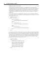
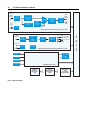
Fig. 6-1. Block diagram
To
ISA
Backplane
Optional
Multi-Modem
ISA Plug-in
Card
To
ISA
Backplane
ISA Plug-in
Card
For Future
Requirements
I
S
A
B
A
C
K
P
L
A
N
E
6. Technical Reference
41
6. Technical Reference
6.1 Calibration
Calibrating the DV2000 involves adjusting a single trimpot only. The pot sets the video output at
the analog monitor output.
Test Equipment
Component digital video pattern generator
75 ohm BNC terminator, 1%
Waveform monitor or ULTECH TV Trigger Mate & 20 MHz oscilloscope
Procedure
q 1. Remove AC line cord. Remove (6) phillips screws from sides of top cover. Remove top
cover.
q 2. Attach AC line cord. Turn unit on. Allow unit and test equipment to warm-up for 15
minutes. Caution: a shock hazard exists with the top cover removed. Do not touch AC
line switch or AC wiring. Apply a stable 1Vpp stairstep pattern to Monitor Video In.
q 3. Adjust R22 trimpot located on the DigMon PC board for 1Vpp at Monitor Video Out
when terminated into 75 ohm.
(end of procedure)
DigMon PC board
R22
Fig. 6-2. Adjustments
!
s
A shock hazard exists with the top cover removed—only qualified
personnel should perform the calibration procedure.
42
ULTECH DV2000 User’s Manual
6.2 Pinouts
GPI General Purpose Interface
Pin
Function
1 GPI Input/Output #1
2 Ground
3 GPI Input/Output #2
LTC Time Code
Pin
Function
1 Ground
2 Ground
3 Inverting Input (-)
4 Non-inverting Input (+)
S-Video Output
Pin
Function
1 Ground
2 Ground
3 Y output
4 C output
Com Ports
Pin
1
2
3
4
5
6
7
8
9
Function
Data Carrier Detect
Receive Data
Transmit Data
Data Terminal Ready
Ground
Data Set Ready
Request To Send
Clear To Send
Ring Indicator
4
3
2
1
4
3
2
1
Notes
(not used)
(input to DV2000)
(output from DV2000)
(output from DV2000, not used)
(input to DV2000, ignored)
(output from DV2000, not used)
(input to DV2000, ignored)
(input to DV2000, ignored)
6. Technical Reference
VGA
Pin
1
2
3
4
5
6
7
8
Function
Red
Green
Blue
(no connect)
Ground
Ground
Ground
Ground
Pin
1
2
3
4
5
6
Function
Keyboard Data
(no connect)
Ground
+5VDC
Keyboard Clock
(no connect)
Pin
1
2
3
4
5
6
Function
MS Data
(no connect)
Ground
+5VDC
KBT1
(no connect)
Keyboard
Mouse
Pin
9
10
11
12
13
14
15
Function
(no connect)
Ground
(no connect)
(no connect)
Hsync
Vsync
(no connect)
43
44
ULTECH DV2000 User’s Manual
6.3 Disk Contents
The current version of DV2000 runs under Microsoft DOS, so many of the files and directories on the DV2000 hard drive will appear familiar to you. Of course, you need to have the
VGA monitor and a keyboard connected to the DV2000 in order to view and navigate
around the DV2000 hard drive.
In addition to DOS, there is a subdirectory under the root called DV2000 (C:\DV2000). This
directory contains four items: the DV2000 applications program (DV2000.exe), a hardware
configuration file (hardware.cfg), a software configuration file (settings.cfg), and a
subdirectory called “jobs” (C:\DV2000\Jobs). The “jobs” subdirectory contains all of the
files associated with the jobs that are stored on your hard drive. A future version of DV2000
software will create a separate subdirectory under \jobs in which to store new jobs.
Hardware Configuration File (hardware.cfg)
Hareware.cfg stores information about the hardware that is unique to your DV2000. The
DV2000 reads the contents of the file at start up. The file is an ASCII text file, and each line
of the file must end with CR LF. If the file does not exist then the default values are assumed.
Line 1:
Line 2:
Line 3:
Line 4:
Line 5:
X.XX
XX
XX
X
Software version
(example “2.23”)
Revision of DigEnc Card
(Default = “1C”)
Revision of DigMon Card
(Default = “1C”)
SuperDrive flag “0” = floppy, “1” = SuperDrive (Default = “0”)
Path for caption/subtitle server. Example: s:\CorpServer\CaptionFiles
Your DV2000 must be equipped with the network option in order for line 5 to be processed.
Software Configuration File (settings.cfg)
Settings.cfg stores all of your current settings. The DV2000 software reads the contents of
the file at start up. The file is an ASCII text file; each line of the file must end with CR LF. If
the file does not exist then a default file will be created by the software.
Line 1:
Line 2:
X.XX
XX
Software version
CC monitor setting:
Line 3: xHH:MM:SS:FF
(Default = “+00:00:00:00”)
Time code offset:
Line 4:
Line 5:
Line 6:
Line 7:
CC Level Low
CC Level High
CC Position
EDH Error Flag Mask
XXX
XXX
XXX
XXXX
Example: “2.23”
“00” = off (Default = “01”)
“01” = CC1 “05” = T1
“02” = CC2 “06” = T2
“03” = CC3 “07” = T3
“04” = CC4 “08” = T4
“09” = XDS (Graze mode)
“10” = XDS (Full mode)
x = sign (“+” or “-”)
HH = hours (“00” - “12”)
MM = minutes (“00” - “59”)
SS = seconds (“00” - “59”)
FF = frames (“00” - “30”)
(“001” - “064”)
(Default = “016”)
(“096” - “144”)
(Default = “126”)
(“001” - “050”)
(Default = “013”)
(“0000” - “FFFF”) (Default = “0000”)
(see EDH spec)
6. Technical Reference
6.4 Specifications
Front panel controls & indicators
Power on/off switch
Reset button
Program video LED
Monitor video LED
Data in LED
Time code LED
Hard disk LED
Setup LED
Floppy drive / LS-120 SuperDrive
Cursor keys
Rear Panel controls & connectors
IEC power output connector, rated 120 VAC at 3A Max or 240 VAC at 2A Max
IEC power input connector for detachable three wire AC line cord
120 VAC / 240 VAC line voltage selection switch
PS-2-style keyboard connector, 4 pin mini-DIN
PS-2-style mouse connector, 4 pin mini-DIN
RS-232 serial interface connector, DB9M.
VGA output connector, DB15F
(1) 800 mVpp serial digital video input BNC, terminated into 75 ohm
(2) 800 mVpp serial digital video output BNCs, with 75 ohm source impedance
LTC time code input, balanced, +4dBu nominal input level, 4 pin mini-DIN
850 mVpp serial digital monitor video input BNC, terminated into 75 ohm
1Vpp monitor video output BNC, with 75 ohm source impedance
Y/C monitor video output mini-DIN, with 75 ohm source impedance
Dual GPI port, pluggable header, with internal 4.7K ohm pull-up to +5VDC
Power
150 Watt, 50/60 Hz
90 VAC to 135 VAC (120 VAC setting)
180 VAC to 265 VAC (240 VAC setting)
Enclosure
Dimensions: 19" W (483) x 3.50" H (89) x 14.5" D (368)
Front panel: 0.125" aluminum, painted
Rear, tray, top: .042” steel, gold iridite
Weight: 18 lbs. (8.2 kg.)
Specifications subject to change without notice
45