1
Table of contents
I Welcome to Compu Live
1. Installing software/interface
2. Demo shows
3. Adding your first fixture
4. Compu Live Overview
II Basic programming
1. Adding your own fixtures
2. Pages and Buttons
3. Preprogrammed buttons
4. Example: create your first scene
5. Record Cycles (cue lists/shows)
6. Keyboard triggering (hotkeys)
III Intermediate programming
1. EasyStep scenes
2. Channel properties: On/Off, Dimmer
3. Group/Individual control of fixtures
4. The X-Y window (pan/tilt)
5. Using the MASTER page
6. Controlling Speed/Size of your scenes
IV Advanced programming
1. Overview
2. The Editor
2.1. Easy Time
2.1.1. How to use Easy Time
2.1.2. How to use Easy Time for movement
2.1.3. Tools and options
2.2. Color Manager
2.3. Copy/Paste and Phasing
3. Fade between scenes
4. External trigerring
4.1. MIDI - Easy Console
4.1.1. EasyConsole, what is it ?
4.1.2. First, setup your controller on screen
4.1.3. How to use EasyConsole
4.2. MIDI - Midi Time Code (MTC)
4.3. DMX
4.4. Clock and Calendar
4.5. Contact closure
4.6. Audio Analysis
1
2
7
11
14
19
18
24
26
29
32
34
37
36
38
41
47
50
52
57
56
56
56
56
58
61
62
64
66
70
71
71
72
73
77
78
79
81
83
5. Page settings
85
V General settings
93
1. Starting parameters
2. Windows management
3. Backup /Technical support
4. Setting up multiple DMX universes
4.1. Using the USB interfaces
4.2. Using the IP interfaces
4.3. Using the Art-Net protocol
VI Appendix
1. DMX512 brief description
2. Accessories
3. IP/Ethernet configuration
4. Troubleshooting
5. Commands summary
92
93
95
96
96
97
99
101
100
103
104
106
108
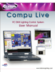
Compu Live
I Welcome to Compu Live
I Welcome to Compu Live
Prologue
Thank you for your interest in the Compu Live control software.
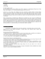
Our User Manual is divided into the following chapters:
1. Welcome to Compu Live
Quick start guide, Overview
2. Basic Programming
3. Intermediate Programming
4. Advanced Programming
5. General Settings
Appendices
In this manual, the most elemental concepts of lighting control are presented early on, followed by
increasingly more complicated software tools and functions as the manual progresses. Though our
software is designed to be simple to use and intuitive to learn, we strongly recommend beginner users
to read this manual consecutively, starting from the first chapters and so on. Intermediate and
advanced programmers will usually skip through sections without a problem.
This first chapter gives users a quick overall look at our software (essential if you are impatient like
most of us). We will walk you through the installation process for the software and the interface drivers.
Then we will play around with our preprogrammed DEMO shows. At the end of this chapter, we will
quickly show you how to add your own fixtures into the software, just in case you cannot wait to test
your own lighting fixtures.
The second chapter will show you the most elemental programming tools within the software. By the
end of this chapter, you should be able to program a decent looking show very quickly.
The third and the fourth chapter describe more advanced (not necessarily complicated) software tools.
This knowledge, along with a little practice, will allow you to create almost any lighting scene/effect your
fixtures can handle.
The fourth chapter briefly describes peripheral software tools in the Compu Live package, such as the
3D visualizer (Easy View), a profile/library editor (Scanlibrary), a music/video/lighting timeline
synchronization tool (Easy Show), and downloading scenes/shows into the internal memory of the
electronic interface (Easy Stand Alone).
The fifth chapter include several starting parameters the user should be familiar with, options for the
windows management and Backup/Technical support
Finally, you will find appendices that include a DMX512 review, MIDI review, list of available
accessories, and a troubleshooting guide.
Page 1
Compu Live
I Welcome to Compu Live
1. Installing software/interface
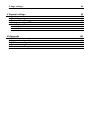
1. Installing the software
Whether you are holding an installation CD in your hands or you downloaded the software from
the internet, the first thing you want to do is install our Compu Live software.
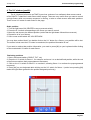
Insert the installation CD in your computer (if you downloaded the software from the internet,
you can skip this paragraph). Once the installation screen is open, select your language and click
NEXT,
then accept the license agreement, and finally click on the INSTALL icon for Compu Live.
Page 2
Compu Live
I Welcome to Compu Live
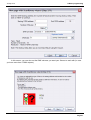
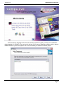
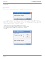
Select the Setup language and accept the license agreement (again). Choose your installation
folder (default is C:SL2006). The next screen will ask if you want to install the software with or without
DEMO PAGES. If you are a beginner user, we recommend you install WITH demo pages.
Page 3
Compu Live
I Welcome to Compu Live
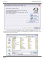
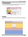
Finally, the setup wizard will ask if you want to start the software in BEGINNER MODE. Again, if
you are a beginner user, we recommend you click YES on the beginner mode option.
You are done! Now, it is time to start playing with our software.
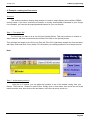
2. Installing USB drivers
If you purchased a software package and received a USB to DMX interface, you will need to install the
drivers for it. You can use the full software without the interface, but you will need this USB-DMX device
if you want to control real lighting fixtures.
Page 4
Compu Live
I Welcome to Compu Live
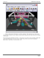
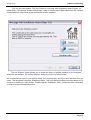
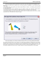
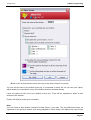
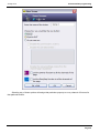
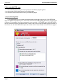
Windows will find the driver and will tell you the device is not validated, and will ask if you wish to
continue. Although Microsoft does not have a numberical registry for this driver, there is no risk of
incompatibility. Click "Continue Anyway".
Page 5
Compu Live
I Welcome to Compu Live
You are done! But remember, the software detects the USB interface when it starts. This means that
you must have the USB interface connected to your computer before you open the control software.
Otherwise, there will be no communication between the software and the interface.
3. Using IP/Ethernet interfaces
If you purchased a Compu Live package with an IP/Ethernet interface, please refer to the Appendix
section for instructions.
Page 6
Compu Live
I Welcome to Compu Live
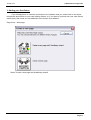
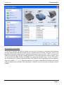
2. Demo shows
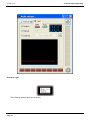
For this section, we assume you installed the software in BEGINNER MODE and that you
enabled the installation of DEMO PAGES. If you did not, you will see many options on your screen
apart from the ones described here, but the information will still be valid.
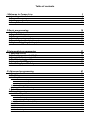
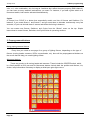
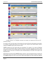
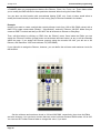
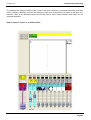
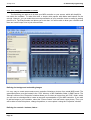
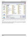
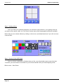
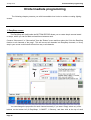
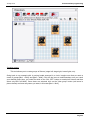
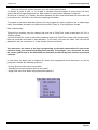
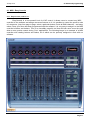
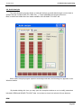
Your screen should look like this:
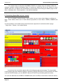
The Compu Live software will display 1 button for every function that the lighting fixture can
perform. There will be 1 button on the screen for every color, gobo, macro, prism effect, etc.
Page 7
Compu Live
I Welcome to Compu Live
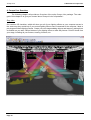
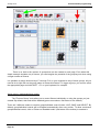
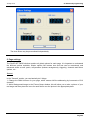
Depending on the type of intelligent lighting that you’re using, there will also be preprogrammed
buttons with generic effects (in this case, the DEMO MOVING HEAD page contains buttons with
movements that are generic to all moving heads and scanners, like circles, random curves, etc).
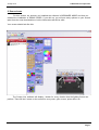
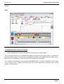
As you can see on the 3D visualizer window, every time you press a button on your screen the
moving heads respond to that command.
Page 8
Compu Live
I Welcome to Compu Live
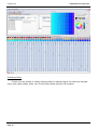
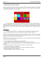
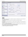
Keep in mind that the 3D window is a real-time visualizer. This means that if you had those 4
moving heads connected to your computer, they would be doing that exact same thing you are seeing
on the screen.
Keep pressing any combination of buttons… play around. If you want to reset everything, double click
on the yellow INIT button. If you find a “look” or “effect” that you like, you can save it by going to:
Button menu – New Scene – As you see now – OK
Page 9
Compu Live
I Welcome to Compu Live
We recommend you create a few scenes like this, so that you get somewhat familiar with the
controls. Once you feel comfortable with the preprogrammed controls in the Demo Moving Head page,
you will be ready to add your own fixtures and learn more advanced programming techniques. We still
recommend, however, that you read this manual consecutively, and advise beginner users against
jumping in between chapters at this point.
Page 10
Compu Live
I Welcome to Compu Live
3. Adding your first fixture
If you already have an interface connected to the software and you cannot wait to test these
movements and effects on your own lighting fixtures (or if you want to preview how your own fixtures
would work), this is how you can add them to the Compu Live software:
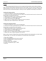
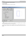
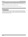
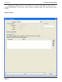
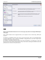
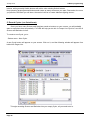
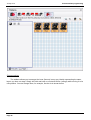
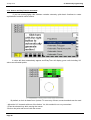
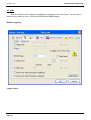
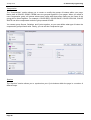
Page menu – New page
Select "Create a new page with Scanlibrary wizard".
Page 11
Compu Live
I Welcome to Compu Live
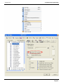
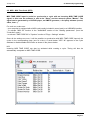
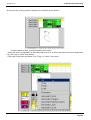
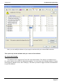
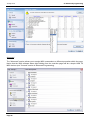
You will be able to browse through the profile library in your computer. Search for your
manufacturer's folder and then your particular fixture (notice there is a VARIED folder where fixtures
from small manufacturers are included).
Page 12
Compu Live
I Welcome to Compu Live
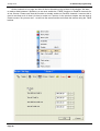
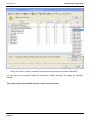
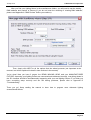
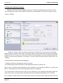
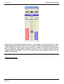
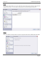
After you find your lighting fixture in the manufacturer folders, you will need to set the starting
DMX address and number of fixtures (if you do not know the meaning of “starting DMX address”,
please read Appendix A “DMX Review” before you continue).
Then, simply click NEXT to all the options that the wizard presents (not important at the
moment, but will be explained in detail in later sections in the manual).
You’re done! Now you have 2 pages: the DEMO MOVING HEAD and your MANUFACTURER
FIXTURE. Assuming your lighting fixtures are connected and addressed correctly, everything shown in
the 3D visualizer should be simultaneously happening with your real lighting fixtures. If you think you
have everything setup correctly and are still having problems, please refer to Appendix D
“Troubleshooting”.
There you go! Keep reading the manual to learn how to program more elaborate lighting
scenes/shows/effects.
Page 13
Compu Live
I Welcome to Compu Live
4. Compu Live Overview
The following chapter will provide an Overview of the entire Compu Live package. The main
goal of this chapter is to give you a better idea of Compu Live’s full potential…
Easy View
Our real-time 3D visualizer, which will show you all of your lighting effects on your computer screen in
the same way they would look if your actual lighting fixtures were connected to the computer. Ideal to
pre-program without lighting fixtures. Create your own stages adding objects and textures, making them
as realistic as you want. Record videos of your lighting shows or take still pictures. Print 2D views from
your stage, including all your fixtures, trussing, furniture, etc.
Page 14
Compu Live
I Welcome to Compu Live
Easy Show
Ideal to synchronize lighting effects with audio and video. Similar to audio editing software, Easy
Show includes timelines where you can drag, drop, expand, scroll your lighting effects, along with Audio
and Video timelines.
Easy Stand Alone
Create your lighting scenes, then download them to the memory of the interface. Depending on
the number of lighting fixtures that you’re using, you can have hundreds, even thousands of scenes
recorded in our small electronic interface. Trigger lighting shows at scheduled times using the
interface’s internal clock and calendar. Activate lighting scenes using simple IO contact closures.
Page 15
Compu Live
I Welcome to Compu Live
Scanlibrary Editor
Create your own profiles or modify existing profiles for lighting fixtures. All effects are included
(color, gobo, gobo rotation, prism, etc). Preview your profiles using our 3D visualizer.
Page 16
Compu Live
I Welcome to Compu Live
Page 17
Compu Live
II Basic programming
II Basic programming
Overview
After reading our "Welcome" chapter, you might have a good idea of what you would like to
accomplish with our Compu Live controller. Now it is time to learn how to create all those lighting
scenes you have in your mind already.
This chapter explores the options available when adding your own fixtures through our “New Page
Wizard”. Then we focus on available preprogrammed buttons for all intelligent lighting. We look deeper
into the “New Scene – As you see now” option. Finally, this chapter explores the triggering of lighting
scenes from your computer's keyboard.
1. Adding your own fixtures
Whether you purchased the electronic interface already or simply downloaded the free software
from the internet, you probably have an idea of what type of lighting fixtures you want to control. The
Compu Live includes a library of about 2,000 profiles from lighting manufacturers from around the
world; most likely your lighting fixtures are included.
Fixtures are grouped inside the Compu Live software into "Pages". Thus, to add your own fixtures, go
to:
Page menu – New page
Page 18
Compu Live
II Basic programming
You can see two buttons. The first "Create a new page with Scanlibrary wizard" opens our
profile library. The second "Create a blank page", adds an empty page of DMX channels in the software
(configuration for these blank pages is described in later chapters).
The first "Explore" button allows you to search the library of profiles installed in your computer
along with the software. The second "Explore" button is a link to our online library.
We recommend you look for your profiles within your computer first, and if you can't find them, then go
online. The third button opens the Scanlibrary Editor. This is an aditional software tool that allows you to
construct or modify your own profiles. Please read the "Scanlibrary Editor" manual for more information
on how to create personalized profiles.
Page 19
Compu Live
II Basic programming
Note: If you cannot find your fixture's profile in the library, please refer to the Scanlibrary Editor
manual.
Once you find your fixture inside your manufacturer's folder, you will need to set a starting DMX
address and the number of fixtures that fit this profile. If you are unfamiliar with the term "starting DMX
address", please read our DMX Review appendix.
Page 20
Compu Live
II Basic programming
In this screen, you can also set the DMX universe you want your fixtures to work with (in case
you have more than 1 DMX outputs).
Page 21
Compu Live
II Basic programming
Look at your lighting fixtures (whether the real ones or the ones inside the 3D visualizer). You
should see all of them turn on, white color, to 50% pan and tilt (if available). If your fixtures fail this
check, then:
1. You selected the wrong profile (some fixtures have different "modes"). You should go back and find
the appropriate profile.
2. You addressed your fixtures differently than the software (Compu Live addresses similar fixtures
consecutively). Figure out if it is better to re-address fixtures in the software or the real world.
3. The fixture's lamp is not ON, in which case, continue with the setup process, there will be a DMX
command to turn it ON within the Compu Live page.
This screen allows you to limit the maximum Pan and Tilt in your moving heads and scanners
(the wizard will skip this step if your fixtures do not have these properties). Setting limits to pan and tilt
channels can be useful, but we recommend you get familiarized with other controller tools first, and
then decide if setting limits for the fixtures is what you need to create your lighting effects. If it is, you
can always change these limits from the "Page Properties" window (described later in the manual).
Page 22
Compu Live
II Basic programming
The next screen asks which preprogrammed movements you want to include (for moving heads
and scanners only). Again, we recommend you include all movements (default selection).
Page 23
Compu Live
II Basic programming
Do not worry about all other options on the screen, once you learn the concepts of the software,
these will be obvious.
There is no limit to the number of pages that you can add. We recommend you to add all your
lighting fixtures from the same type within the same page, and that you do not repeat DMX addresses
across different pages.
2. Pages and Buttons
Pages
Within the Compu Live software, a PAGE corresponds to a group of lighting fixtures of the same
type (manufacturer and model). You can have any number of fixtures within each page, and also you
can have any number of pages. The power behind these PAGES is to control fixtures together
(simultaneously) which allows for very easy programming. Fixtures can also be controlled
independently if you want, as explained in Chapter 4 “Intermediate Programming”.
Page 24
Compu Live
II Basic programming
Do not worry about the options available within this window for the moment, as they will be
explained later in the manual and are not necessary to understand the basics of the software.
Buttons
There are 3 different types of buttons, each with their own properties:
- Scenes (yellow buttons)
- Switches (red buttons)
- Cycles (blue buttons)
Scenes
A Compu Live SCENE is a button that typically recalls a combination of functions and effects
(sometimes known as a "cue" or "look", it can be movement with colors, gobos, prisms, etc). There can
be 1 and only 1 Scene selected at a time inside each Page. This means that every new Scene that you
activate will release the previous scene.
Switches
A Compu Live SWITCH is a button that typically recalls a single function or effect (i.e. 1 movement, or 1
Page 25
Compu Live
II Basic programming
color, or 1 color combination, etc). As long as 2 switches don’t affect the same property (DMX channel),
you can have as many switches activated as you want. For instance, if you add a gobo switch to a
movement switch, both can be activated simultaneously.
Cycles
A Compu Live CYCLE is a button that sequentially recalls cue lists of Scenes and Switches. For
instance, if you create Scene 1 and Scene 2, and you want them to alternate continuously every few
seconds, a Cycle can include these 2 scenes and define the timing in between.
You can create new Scenes, Switches, and Cycles from the “Button” menu on the top. Simple
instructions to create Scenes, Switches, and Cycles follow in upcoming sections.
3. Preprogrammed buttons
Using preprogrammed buttons
Every time you create a new page for a group of lighting fixtures, depending on the type of
fixtures (moving heads, scanners, LEDs, conventionals, etc), there will be preprogrammed buttons on
the screen that will help you create lighting effects.
Movement buttons
These are generic to all moving heads and scanners. These include the CENTER switch, which
is a fixed position at 50% pan and tilt. Movement buttons include both the position and dimmer, iris,
shutter, lamp information necessary to display a white/open gobo light source.
Page 26
Compu Live
II Basic programming
Color, gobos, effects, etc…
Depending on the features of individual lighting fixtures, there will be a button that will
correspond to every function that a lighting fixture can perform. You can visualize most of these in the
3D window. The ones that you cannot visualize (like macros, for example) still have a button on the
screen that would trigger the lighting effect if the real lighting fixture was connected to the computer.
X-Y
With the X-Y buttons, you can define a fixed position for the light beam of any scanner or
moving head. There will be one X-Y button for each fixture in the page, so that each can be controlled
individually. The X-Y buttons control only the pan and tilt channels, and not the dimmer, iris, etc. that
are necessary to have a visible light beam. For this reason, we recommend you use any
preprogrammed Movement button (in particular CENTER) to have a visible beam first, and then move
your fixtures to their position.
Page 27
Compu Live
II Basic programming
RGB
If your lighting fixture has RGB or CMY capability, there will be a Color Wheel button that will
allow you to select the color displayed by the fixtures and the intensity of the light beam.
As we explained earlier, you can press different buttons simultaneously. For example, you can select
the Circle movement, then add a Blue color, then add a Star gobo, then add a Prism effect, then add
Gobo Rotation, then fix a couple fixtures in a defined position, and so on…
Page 28
Compu Live
II Basic programming
4. Example: create your first scene
Overview
This section provides a step-by-step example to create a simple lighting scene with the DEMO
moving heads. If you have some kind of scanner or moving head already connected to your Compu
Live controller, you can use the preprogrammed buttons for your own fixtures.
Step 1 - Turn lamps ON
The first thing you want to do is turn ON your lighting fixtures. This can be done in a number of
ways. However, the most convenient at this moment is to click on the [Center] button.
This will make the lamps to turn ON, move Pan and Tilt to 50% (light beam straight out from the base),
with Open Gobo and Open Color (white). This should be your starting position for most simple scenes.
Note:
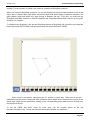
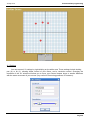
Step 2 - Adjust beam positions
Using the X-Y buttons, you can adjust the position of any of the beams coming from your
fixtures. There will be 1 button for each fixture. Simply click on one button, then move the red arrow
inside the white area, then click on the next button, move the red arrow, and so on...
Page 29
Compu Live
II Basic programming
Step 3 - Adding effects
Once you have your positions adjusted, you should as many effects to your lighting scene as
you want: colors, gobos, prism, etc. Feel free to use as many of the preprogrammed buttons available.
Notice that you can activate effects by clicking on them once, and deactivate them if you click on them
a second time.
Step 4 - Save AS YOU SEE NOW
Once you find a combination of buttons that you like, you will probably want to save that look.
To do this, you must create a new button on your screen that will return your saved lighting scene:
Button menu – New Scene
Page 30
Compu Live
II Basic programming
(Button menu is the pull down menu at the top of the main Compu Live screen)
You can set the name of the button at the top. It is important to select the "As you see now" option,
which allows you to include all or any of the buttons that you activated already.
Leave the options at the end of the window as they are. These will be explained in detail in later
sections of the manual.
Finally, click [OK] to create your new button.
Note:
You can create a “New Switch” instead of a New Scene, if you want. The only difference will be, as
explained on the previous section, that during playback a Scene button will replace any other Scene
Page 31
Compu Live
II Basic programming
buttons, while generally Switch buttons will add to other existing Switch buttons.
Keep pressing preprogrammed buttons and create as many scenes as you want. Remember, the more
you practice, the faster you will learn, the easier it will be to create elaborate lighting shows...
5. Record Cycles (cue lists/shows)
Once you have many Scenes and Switches saved as buttons on your screen, you will probably
want to reproduce them sequentially. CYCLES will help you do this. A Compu Live Cycle is a cue list of
Scenes and Switches in time.
To create a new Cycle, go to:
- Button menu - New Cycle
A new Cycle button will appear on your screen. Click on it, and the following window will appear from
behind the Pages List:
To begin recording Scenes and Switches into your empty Cycle, all you need to do is:
Page 32
Compu Live
II Basic programming
1. Click on the Cycle button
2. Start clicking on the Scene and Switch buttons in the order you want them to be played
3. When you are done, click the [PLAY] button inside the Cycle editor window, and click on [YES] when
asked if you wish to save the Cycle
Clicking Play will start running the cycle, scrolling through your buttons. If you wish to change the timing
between each Scene or Switch, first click on [STOP], and then click on the TIME button (with [2.18]
written on it, right underneath the Cycle clock). The "GO" option inside the TIME window allows you to
scroll through the cycle using your keyboard's [PgDn] and [PgUp] keys.
If you want to delete a step within your Cycle, click Stop and then use the CUT tool (scissors). If you
want to add a Scene or Switch, click on the RECORD button (red circle underneath PLAY), and then
click on PLAY to end the recording process and preview your Cycle.
The LOOP option (circular arrow on the right end of the window) allows you to select whether you want
your cue list of scenes and switches to repeat itself, or simply run once and remain in its final state.
Note:
To add FADE times to your Scenes, you must double-click on the Scene button first, then go into
- Button menu - Settings
Select "Scene", the last item on the left. In this window you can set the fading times for your
scenes (only Scenes are allowed to have Fade In/Out times, not Switches).
Page 33
Compu Live
II Basic programming
6. Keyboard triggering (hotkeys)
Buttons on the screen can be triggered using your computer’s keyboard, along with your mouse.
You can assign any button on the screen to any key on your keyboard. To do this, you need to go into:
- Button - Settings
Select the "Trigger" option on the left, then tick the "Trigger key" box on the top, and assign
whatever letter you want. "Flash mode" creates keys which are only active while the keys are physically
being pressed; the moment you release your finger from the keyboard, they will automatically become
inactive (only works with Switches, not Scenes). Try this FLASH key option with the Strobe effect, for
example.
A useful shortcut to assign keyboard triggering:
1. Activate the button by clicking on it with your mouse
2. Simultaneously press the [CTRL] key and the [letter] key that you want to use
Note: A “key” is defined as any character on your keyboard; i.e. [q] and [Q] are different, so are [3] and
[#], etc. This allows you to have around 90 hotkeys from your keyboard.
You will see that a small blue letter (the one you pressed on your keyboard) will appear inside the
button. Every time you press this key, that button will be activated (and inactivated, if it is a Switch).
If you assign the same letter on the same button twice, the shortcut letter inside the button will turn
Page 34
Compu Live
II Basic programming
green, which represents FLASH keys (explained above).
You can only use a key once within each page, but you can use the same key on multiple pages. This
allows you to trigger effects simultaneously across all your lighting fixtures (i.e. try the red color, or the
closed shutter, etc, across multiple pages). The Master page makes this simultaneous control much
easier, and will be explained in the following chapter.
Note: Touchscreens, MIDI devices, DMX wings, and IO keypads can also trigger any button within the
Compu Live software, as you can see inside the Button Settings window. These will be explained
further in Chapter 4 “Advanced Programming”.
Page 35
Compu Live
III Intermediate programming
III Intermediate programming
The following chapter presents you with intermediate level tools to continue creating lighting
scenes.
1. EasyStep scenes
The EasyStep rack (tab) inside the BUTTON EDITOR allows you to create simple scenes based
on steps, where you can set fade and wait times between each.
Create a "New scene" or "New switch" from the "Button" menu and then select the "Link the EasyStep
function to all channels of the page". This will convert all channels into EasyStep channels, so every
step in your scene could include effects from any or all channels.
You can change the properties for each channel manually, if you want. Simply select any of the
buttons on the bottom left (2 EasySteps, 1 ON/OFF, 1 Dimmer), and then click at the top of each
Page 36
Compu Live
III Intermediate programming
channel. For the moment, it is best if you leave all channels as EasyStep channels.
When you create an EasyStep sequence, you can go through your steps for each channel in one of two
ways: with or without fade. Light beam movement might look better fading in between positions, but
gobo rotation might look better as a step change in between the two. To do this, you must use the
"EasyStep with fade" function on Pan/Tilt channels and "EasyStep without fade" function on the gobo
channels, for example.
To change these properties, use the two EasyStep buttons at the bottom left, where the top ramp-like
button represents WITH FADE, and the second step-like button WITHOUT FADE).
Each corner in the picture represents the X-Y position in each step. These can be moved
individually with the mouse. Steps with fade in between show dotted lines in between the corners in the
shape area. Steps can be selected by clicking on the corresponding point (white area) or directly from
the step list at the top.
To set the FADE and WAIT times for each step, use the number boxes at the top
(minutes.seconds.1/100). The top box controls fade and the bottom one wait times.
Page 37
Compu Live
III Intermediate programming
Other available functions on the EasyStep rack are copy, cut, paste and insert step. The PLAY
button allows you to preview your scene. You can choose to make your scene loop or not. Finally you
can convert your EasyStep scene into an EasyTime sequence (advantages of EasyTime will be
explained in the Advanced Programming section).
2. Channel properties: On/Off, Dimmer
When you create new Scenes or Switches, you are given the option to "Link the Dimmer (or
EasyStep) function to all channels of the page".
Page 38
Compu Live
III Intermediate programming
Selecting any of these options will assign that particular property to every channel of fixtures for
that particular button.
Page 39
Compu Live
III Intermediate programming
If neither "Dimmer" nor "EasyStep" functions are selected, the channels will have the OFF
property by default.
If a channel is OFF, the final output for this channel will not be affected by this particular scene/switch.
For example, a COLOR switch has all of its channels in OFF, except for the COLOR channel, which is
assigned a DIMMER property and a particular value.
DIMMER channels are fixed values within the scene/switch. For example, if you have an EasyStep
scene, where the light beam fades in between positions and all gobos and colors are kept the same
throughout the scene, you can assign these color and gobo channels the DIMMER property and set the
constant value for this scene. This dimmer value will automatically be the same for all steps in the
EasyStep scene.
ON channels are just like 100% DIMMER channels. However, we must emphasize that a 0% dimmer IS
NOT the same as an OFF channel. An OFF channel does not affect the channel in question, whereas a
0% DIMMER assigns this value to the channel, which would replace any values coming from different
Page 40
Compu Live
III Intermediate programming
buttons.
Note:
3. Group/Individual control of fixtures
Fixture grouping is one of the most powerful tools within our control software.
As you may have noticed, our preprogrammed buttons (movement, color, gobo, effect, etc) operate on
all fixtures within a page. If you want to have independent control of your lighting fixtures (assign each a
different color, for example), you will find our Fixture Group tools very helpful.
(This function is not available in the software's BEGINNER mode. To change to EXPERT mode, simply
go to: Controller menu - Expert mode. Once you are in Expert Mode, go to: Windows menu - Reset
positions - Reset to tabs.)
Page 41
Compu Live
III Intermediate programming
Fixture positions
The sofware allows you to arrange the icons (fixtures) in any way, ideally representing the same
layout you have on stage. Simply left-click and hold on a selected fixture (orange) while moving it to its
new position. You can arrange them, for example, like the circle shown below.
Page 42
Compu Live
III Intermediate programming
Creating groups
This tool allows you to create groups of fixtures (stage left, stage right, house lights, etc).
Going back to our example with 4 moving heads arranged in a circle, imagine now that we want to
create 2 groups [Mo1 + Mo3] and [Mo2 + Mo4]. Click on the icons to select/unselect until you reach
your desired group (also, you could first click on the "ALL OFF" button to unselect all fixtures and then
select only Mo1 and Mo3). Once these are selected, click on the "New group" button (red arrow in
picture below) and enter any name you want, in this case [Mo1 + Mo3].
Page 43
Compu Live
III Intermediate programming
There is no limit to the number of groups that can be created in each page. Even when this
simple example includes only 4 fixtures, you can imagine the potential of the grouping tool when using
a larger number of fixtures.
It is possible to assign shortcut keys F1 through F12 on your keyboard to any of these groups. All you
need to do is right click on the group name to access this feature. To trigger a group, you need to select
the appropriate page and click SHIFT + F1 on your keyboard, for example.
Using groups / Individual fixture control
The "Fixtures Group" tools allow you to control fixtures individually or using the groups you just
created. By default, this tools will be disabled (green arrow above, first button on the toolbar).
There are 3 different modes to use this group/individual control fuction: LIVE, SAVE, and SELECT. By
default, group/individual control will be disabled automatically after every action. To allow continuous
group/individual control, click on "Return to Disabled mode" (last button of the toolbar) to unselect it.
Page 44
Compu Live
III Intermediate programming
LIVE mode
To use this mode, select the second button of the toolbar (remember that, by default, LIVE will
be disabled after every action unless you click and unselect the last button "Return to disabled").
Back to our 4 Moving Head example, imagine you want to have you 1st group [Mo1 + Mo3] in cyan and
[Mo2 + Mo4] in red.
0 - Turn the light beam ON (click on CENTER or any movement button)
1 - Select the LIVE option (2nd button) and release the "Return to disabled" option (last button)
2 - Select the [Mo1 + Mo3] group
3 - Activate the Color Cyan button on your normal fixture page (if you have the 3D visualizer open, you
will notice how ONLY fixtures 1 and 3 change color)
4 - Click on the "Invert selection" button (to the left of ALL OFF). This action will unselect the first gruop
and automatically select the second
5 - Activate the Color Red button on the page
6 - Disable group/individual control (1st button on the toolbar) to return everything to normal.
7 - Save a new scene/switch AS YOU SEE NOW
LIVE mode is the most versatile function in this toolbar. Most of the time you will be working with
preprogrammed buttons and LIVE, then creating scenes/switches AS YOU SEE NOW. During LIVE
performances, when "on the fly" control is required, the LIVE button will become very useful.
SAVE mode
As you probably realized, LIVE mode modifies button properties momentarily. The
group/individual fixture information is not saved within the button, so that once LIVE mode is disabled,
for example, all preprogrammed buttons will work on all fixtures.
If you want to save group information in a button, you will need to use the SAVE and SELECT modes.
Imagine now you want to have your assign the cyan color button exclusively to the 1st group [Mo1 +
Mo3] and the red color button exclusively to the second [Mo2 + Mo4].
0 - Turn light beams ON (CENTER or any movement switch)
1 - Select the SAVE option (3rd button) and unselect "Return to disable" (last button)
2 - Select the [Mo1 + Mo3] group
3 - Activate the Color Cyan button on the page
4 - Click on "Invert selection" (to the left of ALL OFF, or select/unselect manually)
Page 45
Compu Live
III Intermediate programming
5 - Activate the Color Red button on the page
6 - Disable SAVE (1st button of the toolbar)
If you look closely at your 2 color buttons (red and cyan), you will see a small 'S' flag inside. This means
that a group (or individual fixture) was assigned and saved into the button, which will not be disabled
even when the SAVE mode is no longer active.
If you wish to reset your preprogrammed buttons back to normal, you need to redo the SAVE
procedure (except this time you need to select ALL fixtures before you assign them to the button).
Using the SELECT mode (explained below) allows you to reset groups in your preprogrammed buttons,
also. Remember that, unless you change them, preprogrammed buttons work on all fixtures within the
page.
SELECT mode
The SELECT mode works in a very similar way as the SAVE mode, except backwards. In
SAVE, we first selected the group, then we selected in what button we wanted it assigned.
In SELECT mode, we first choose the button and then we assign a group to it. This tool is very useful
when you have a large number of fixtures and complicated groups, because you can see the groups
assigned to each button without the risk of losing them.
SELECT is also very useful during live performances if you want to change the group information inside
a button without activating that button.
0 - Turn the light beam ON (CENTER or any movement switch)
1 - Select the SELECT option (4th button) and unselect "Return to disable" (last button)
2 - Select the Color Cyan button pressing "SHIFT + click" (this method will select the button, but will not
activate it)
3 - We can see that the [Mo1 + Mo3] group is selected from the previous example
4 - Add the selection of the [Mo2 + Mo4] group
5 - Select the Color Red button using "SHIFT + click" (button selected but not activated)
6 - Add the selection of the [Mo1 + Mo3] group
7 - Disable the SELECT function (1st button of the toolbar)
Page 46
Compu Live
III Intermediate programming
4. The X-Y window (pan/tilt)
The X-Y buttons (referred to as TAKE in previous versions of our software) allow mouse control
of the PAN/TILT channels in each fixture within a page. These are very useful when you want to control
a single fixture while a movement sequence is running, or also to create scenes with static positions.
There is one X-Y button for each fixture in the page.
Static position
1. Turn the light beam ON (CENTER or any movement switch)
2. Press the X-Y switch corresponding to the fixture you want to control
3. Move the red arrow to the desired position (notice that the light beam follows this movement)
4. Repeat for all of your fixtures
5. Save a new scene/switch AS YOU SEE NOW
You may have noticed that if you double click on the X-Y button for a fixture, your position will be lost.
The reason is that once the X-Y button is unselected, the position information is lost.
If you want to retrieve that position information, you need to press [Alt] on your keyboard while clicking
on the unselected X-Y button for each fixture.
Retrieving positions
1. Start a movement switch (CIRCLE, TILT, etc)
2. Press the X-Y switch for fixture 1, for example, and move it to a desired fixed position, while the rest
of the fixtures continue their preprogrammed movement
3. Click on the X-Y switch for fixture 1 to unselect it, allowing fixture 1 to continue the preprogrammed
movement
4. Press [Alt] on your keyboard while clicking on the X-Y switch for fixture 1 (notice how pressing [Alt]
makes the light beam go back to the position assigned previously)
Page 47
Compu Live
III Intermediate programming
Example
The following example will show you how to create two fixed position scenes within the Master
page, using the Demo Moving Head page and 3D Demo stage. Your first scene will have all light
beams pointed to the drum set, while the second to the music keyboard on the stage. Furthermore,
these scenes will be compressed together, allowing for easier organization and editing of the positions.
Creating the drums position
1 - Click on the "@Center" scene to open the light beams
2 - Select the X-Y button (previously known as TAKE) for the first fixture and move the red arrow until
the light beam is pointed at the drum set
3 - Repeat the procedure for the 3 remaining moving heads
4 - Click anywhere on the Master page to select it
5 - Create a new scene AS YOU SEE NOW
6 - Make sure all 4 X-Y buttons and the "@Center" scene are selected
7 - Rename the scene "Position Drums", then click OK
Creating the keyboard position
1 - Click on the "@Center" scene to open the light beams
2 - Select the X-Y button (previously known as TAKE) for the first fixture and move the red arrow until
the light beam is pointed at the music keyboard
3 - Repeat the procedure for the 3 remaining moving heads
4 - Click anywhere on the Master page to select it
5 - Create a new scene AS YOU SEE NOW
6 - Make sure all 4 X-Y buttons and the "@Center" scene are selected
7 - Rename the scene "Position Keyboard", then click OK
Now you have 2 scenes, Position Drums and Position Keyboard, each represented as a button inside
the Master page. The next step in this example is to compress both scenes together.
1. Page menu - Settings
2. Select COMPRESSION from the menu on the left
3. Click on the NEW button to create a new group
4. Name it POSITION
5. Change "Button type" to SCENE
6. Change "Compressionn type" to TAKE
7. Click OK
Page 48
Compu Live
III Intermediate programming
X-Y Settings
You can access X-Y settings by right-clicking on the white area. These settings include locking
pan (X) or tilt (Y), allowing better control of your fixture, and a resolution control. Changing the
resolution of the X-Y window will allow you to move your fixtures' beams larger or smaller distances
with the same movement of your mouse (very useful for fine tuning positions, for instance).
Page 49
Compu Live
III Intermediate programming
5. Using the MASTER page
The MASTER page allows you to bring fixtures from different pages together:
- You can record scenes using fixtures from multiple pages
- You can add scenes and switches coming from different pages
1. As you see now (global)
In the same way you can create new scenes within each page using the AS YOU SEE NOW
option, the Master Page allows you to create new scenes that include lighting effects from all pages and
all fixtures. For example, if you have two pages in your controller, 1 SCANNER and 1 MOVING HEAD,
and you select the CIRCLE movement scene in each, then you click on the Master page and create a
new scene, the AS YOU SEE NOW option will include both of these effects from both of these pages.
Page 50
Compu Live
III Intermediate programming
2. Drag and drop into Master buttons
It is easy to edit a Master scene/switch after it has been created. All you need to do is left click
on a button within the conventional fixture pages, and drag it into the Master button. Select "Add to the
button" to replace its properties with those included in the dragged button.
3. Playback page
If you are installing and programming the software for somebody else to use, and you wish to
avoid possible problems (erasing scenes, etc), you can leave your customers with a simple PLAYBACK
PAGE.
Page 51
Compu Live
III Intermediate programming
The easiest way to leave this PLAYBACK PAGE is to simply close all windows within the
software controller (except the Master Page, of course) by clicking the [X] on the titlebar for each
window. After this, you want to lock all windows to prevent users from closing your Master page as well.
Go to - Windows menu - Reset positions - Lock docked windows -
6. Controlling Speed/Size of your scenes
As you probably realized already, some buttons on your screen have faders (or sliders) on
them. These faders control one of three different properties in each button: SPEED, DIMMER and
SIZE.
It is also possible to show faders that control these same properties for all buttons within a page:
- Page menu - Display - Live toolbar Button
You can see the new toolbar appear above the buttons on the selected page. The three faders
on this toolbar will control whatever button is selected (a SELECTED button is not necessarily the same
as an ACTIVATED button, you can SELECT without ACTIVATE by left-clicking with the mouse).
You can also add either the SPEED or DIMMER fader (but not SIZE) to each button. Select the button,
Page 52
Compu Live
III Intermediate programming
then go to
Button menu - Button Settings
Select the "Dimmer/Speed" tab and select which fader you want to show in that particular button.
The Speed function
If you want to increase (or decrease) the speed of a sequence (Easy Time or Easy Step) in real time
you must use the SPEED function. This feature allows you to modify the speed property without editing
the button. Even when the fader position is saved for each button, none of these changes are saved
inside the original program.
You should see a SPEED fader in preprogrammed buttons that control movement, color wheel rotation,
gobo rotation, strobe, etc.
The Dimmer function
This function allows you to modify easily the DMX level of certain channels in real-time. You should see
Page 53
Compu Live
III Intermediate programming
a DIMMER fader on preprogrammed buttons like Dimmer, Zoom, Iris, Focus, etc. These faders allow
you to modify the DMX values for those particular channels without using the button Editor.
You can also use this function with conventional lighting (PAR, etc). Such a button would allow to
modify the beam intensity in real-time for one or any group of fixtures included in the button.
Example
Imagine you want to create a switch that controls dimmer levels from 100 to 200 (DMX values) with a
fader. First, create a new switch ("Button" - "New Switch"), and call it "Dimmer 100-200". Make sure you
create an EMPTY switch and that you DO NOT link all channels to Dimmer or EasyStep.
Then, edit this button by clicking on "Edit" from the "Button" menu. Once inside the Editor you can
assign the "Dimmer" function (purple button on the bottom left-hand corner) to any or all the channels
within the page. If you assign the Dimmer property using the mouse's left click, you will see a full
Dimmer, with maximum 100% and minimum 0% (255-0DMX).
If you right-click to assign the Dimmer, however, you can define the minimum and maximum levels for
that channel.
Set the minimum and maximum levels to 100 and 200 DMX, respectively, then close the Editor
and save changes. You now have a button that can control a dimmer between DMX values 100 to 200.
You can use the Toolbar Dimmer fader to change this value, if you want.
Page 54
Compu Live
III Intermediate programming
You can also add a small fader to the button. To do this, select your new button nnd go to - Button
menu - Button Settings - Dimmer/Speed tab -. Then select:
- Show the Dimmer fader
- Draw the fader on the button
- Use the minimum and maximum levels of each channel
There you go! now you have a button with a fader that controls the DMX output between 100 and 200
for a particular channel only. You can verify the DMX signal from the OUTPUTS window (black area at
the bottom of the controller)
Setting minimum and maximum dimmer levels is necessary, for example, when using a channel
controlling a shutter (e.g. Blackout from 0 to 99, Dimmer from 100 to 200 and Strobe from 201 to
255%). This way, you can have several faders within the same channel, each controlling a particular
fragment of the whole DMX range.
The Size function
This function allows you to increase or decrease the size of a movement. Imagine a scene with a
simple tilt movement. If you want to reduce the amplitude of the movement without editing your scene,
you must use the SIZE function from the Toolbar. All you need to do is move the fader on the toolbar
while the scene is running. You will be able to see the changes in real-time on your fixtures.
Page Dimmer and Speed
You can also use the DIMMER and SPEED functions as global parameters for the entire page:
- Page menu - Display - Live toolbar page Make sure that you keep track of the changes you make using this toolbar. The Live toolbar for the
page has priority over all the buttons inside the page.
Page 55
Compu Live
IV Advanced programming
IV Advanced programming
1. Overview
This chapter introduces all advanced features of the sofware (the editor screen, the fade
function, the external triggering...). These parts of the sofware require to understand the difference
betweeen a scene and a switch, to create and edit a new button, to record a cycle, to arrange the
user-screen...
2. The Editor
2.1. Easy Time
2.1.1. How to use Easy Time
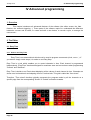
Easy Time is an advanced tool which must be used to program movements (circle, curve...). If
you want to simply create steps, it is easier to use Easy Step.
Easy Time is a tool which enables you to control channels in time. Each channel is programmed
independently. "EasyTime" has been designed for maximum ease and convenience when programming
"Scenes" and "Switches".
Easy Time is similar to an Excel-sheet displaying all the values of each channel in time. Channels are
shown on a horizontal axis and elapsing time on a vertical axis. This grid is called the "time sheet".
Therefore, "Time sheet" therefore globally represents the progress made by all the channels on a
specific page from the corresponding "Scene" or "Switch" activation onwards.
Page 56
Compu Live
IV Advanced programming
Each line refers to a specific moment, since the button was activated.
To activate a period of time, i.e. to be able to visualize what will happen at some point, just move
(yellow) edit line to appropriate time-cell. Each column in a time-sheet represents a channel.
As soon as a "Scene" or a "Switch" has been activated, the time-sheet associated with this button will
be read from line 000'00'00 to the final line containing information.
To program a time-sheet with fade effects, you may program all cells in sequence but to make things
easier, this software includes very efficient tools such as "Fade" or "Cut/Copy/Insert" modes.
Now a little training...
Things will go smoothly once the channel has been set in "EasyTime" mode as was done for "On" or
"Dimmer" modes.
Just click "EasyTime" mode to pilot all the channels required in "EasyTime" mode (click and drag leds).
Now just scroll the time-sheet to time-indication. To set value, just move the fader. The value will be
displayed in the cell concerned, i.e. at the channel column concerned.
You must move the cursor to the line corresponding on the total expected time for your scene
before to setup your channels with EasyTime function. For example : for a 10s scene, we move
the cursor (yellow line) to the 00m10s00 line and then we affect EasyTime function on selected
channels.
In case there are blank cells in between the latest time programmed and current time, you will be
prompted to answer the following questions :
- Prolong previous value up to current time?
- Gradually move from previous value to new value?
- Assign new value from latest cell programmed onwards ?
Page 57
Compu Live
IV Advanced programming
2.1.2. How to use Easy Time for movement
If you use moving lights, this software contains extremely quick basic functions to create
sophisticated vectorial motion-effects.
A circle will then automatically appear and EasyTime will display green cells including X/Y
values as referential points.
By default, a circle is drawn from 4 points. To move any of these, several methods can be used
:
- Adjust the X/Y channels with one of the faders. Yet, this method is not very convenient.
- Press the shortcut key while moving the mouse.
-Click on the point and move it with the mouse.
Page 58
Compu Live
IV Advanced programming
As you can see, moving a point is carried out in real time on the fixture !
To add or delete a point, several methods can be used:
- Select the cells corresponding to the referential point (2,or 4 cells if the fixture has micro-steps) then
use "Cut,Copy or Insert" from toolbar.
- Click right on the point and select "Cut","Copy" or "Insert " from menu.
Page 59
Compu Live
IV Advanced programming
There are 3 different types of vectorial movements :
- Curve (e.g. a Circle)
- Line (e.g. a triangle)
- Positions (going straight away from one point to another)
NB:
- A channel operated by a vectorial movement in EasyTime can be identified by green cells whereas
red cells indicate that the channel is in "non vectorial" mode
- In one button, each fixture can only be assigned one type of vectorial movement (curve, line or
positions). However, channels can be converted into "non vectorial" mode, then any cells can be
modified.
Page 60
Compu Live
IV Advanced programming
2.1.3. Tools and options
EasyTime : "Fade" function
The "Fade" function makes it possible to create a fade-effect in between 2 cells by computing
intermediate values. It can only be used with cells in "Not vectorial" mode (red cells).
To use the "Fade" function, first select a block of vertical cells, then click on "Fade" function. You will
then have an alternative :
"linear" fade in between the 1st and last cell : intermediate cells are totally re-computed.
"fragmented" fade in between each cell : intermediate cells are taken into account ; this process
re-computes as many intermediate fades as necessary to adjust to the number of lines.
NB : A fade can apply to several channels in one go ! Just select cells from several columns.
EasyTime : "Play" function
The "Play" button can be used at any time to visualize or stop programming in process.
When you edit a button after clicking it, the "Play" mode is necessarily active since the button itself is
active...
When editing a pre-selected button without any prior shift-click, the "Play" mode is necessarily inactive
since the button itself is inactive...
NB : It is essential to stop the "Play" mode to modify the "EasyTime" time-sheet.
EasyTime : "Loop" function
If "Loop" mode is activated, a "time-sheet" will be played over and over again.
If "Loop" mode is off, it will just be played once and each channel will remain unchanged and set on the
latest value specified in the "time-sheet".
NB :
- If "EasyTime" programming time is the same for all the channels, (they all end up in the same line)
then the loops will be identically recurrent; if at some point in the time-sheet, two channels have a
similar value, then two hours (and a few minutes or seconds) later, they will have this value again
simultaneously ; channels are always synchronized.
- If "EasyTime" programming time is different for all the channels (not all of them end up in the same
line) then they will not recur simultaneously ; each channel will work independently ; each channel
behaves as if it had its own loop and stands totally de-synchronized.
- This function is extremely powerful, if de-synchronized channels are used you will get
seemingly-random combinations which are ideal if you wish to brightly illuminate light garlands, a ceiling
or a solo on the drums.
Page 61
Compu Live
IV Advanced programming
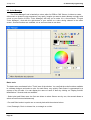
2.2. Color Manager
The "Color Manager" tool is basically a colour editor for RGB or CMY fixtures. It allows to create
either static or dynamic colour sequences very easily. Imagine you want to load a bitmap or simply write
a text on your matrix of LEDs, "Color Manager" will help you to make it in a few seconds. To open
"Color Manager", click with the right button of your mouse on a color mixing channel in the editor
screen. Several functions are available, let us see know how to use them:
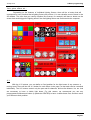
Basic tools
The basic tools are situated in the "Tools" area of the window. You can find the main functions available
in a bitmap designer and select a color for each fixture very quickly. Each fixture is represented by a
square on the left side. You can display the name of each of them by clicking on "Display fixtures'
identification". Several tools are available:
- Select pixel and Select area: the first one allows to select fixtures one by one, the second allows to
select several fixtures simultaneously
- Pen and Paint bucket: to paint one or several pixels with the selected colour
- Line, Rectangle, Circle: to draw a line, a rectangle or a circle
Page 62
Compu Live
IV Advanced programming
- Pipette: to pick a color from the fixtures area
- Copy, Paste: to copy or paste pixels
- Load an image: to draw an image (BMP, JPG...) with your fixtures
You must use the colour picker to change the colour of the selected pixel(s). You can also enter the
RGB values manually.
Text wizard
The text wizard allows to write easily a text on your matrix. You can make either static or scrolling text,
choose the font, the background color...You must click on the "T" button ("Wizard" area) to open the
following window.
Here we must enter our text and then choose a font and a colour. You can specify a colour for
the text and for the background. It is also possible to move your text vertically and/or horizontally with
the "Horizontal offset" and "Vertical offset" cursors. Then, if you want your text not to be static, you must
select the type of movement from the list situated in the "Movements" area. The cursor in the "TAPE"
Page 63
Compu Live
IV Advanced programming
area makes it possible to change the speed of the scrolling.
2.3. Copy/Paste and Phasing
This feature is available with "EasyTime" and "EasyStep" racks, let us see now how to use it.
With this new tool, you can quickly copy and paste a sequence to one or several fixtures. When your
sequence is ready to be pasted to the other fixtures you must click on the "Copy" button (below the
"EasyTime" or "EasyStep" button) and then select the channels you want to copy (like we did before).
The following window appear:
By default, "Simple" is selected. That means that the sequence will be pasted to the selected
fixture. If you want to paste the same sequence to more than one fixture you have to select "Advanced"
and then select the fixtures. Three options are available:
- All : means that the sequence is pasted to all (same) fixtures
- Selected group : means that the sequence is pasted only to the fixture of the selected group
- Specified fixtures below : you can select the fixtures one by one
Page 64
Compu Live
IV Advanced programming
The phasing tool allows to easily create a "wave" with your scanners or a rainbow effect with your CMY
colour changers. Basically, this new tool allows to copy some channels from a fixture to the other one.
However, there is an advanced option which helps you to add a delay between each fixture for the
selected sequence.
How to create a "wave" or a rainbow effect
Page 65
Compu Live
IV Advanced programming
Once we have made this, we can copy the "PAN&TILT" channels and paste to one fixture. The
"Copy/Paste" window appears and we must select "Advanced" to access the phasing function. After
having selected "Phasing (only with EasyTime or EasyStep channels)", you must specify the type of
phasing:
- Manual means you have to specify the delay manually with the cursor
- Other options are pre-programmed delays taking the number of fixtures into account
3. Fade between scenes
It is possible to fade from one scene to another one. For instance, this is really useful to go from
one position to another one very slowly, to open/close the dimmer of your lights...A few things need to
be checked before to start programming our 2 scenes. First of all the "FADE" function must be allowed
on the channels we want to use. To do so, we open the "Page Settings..." window from the menu and
we go to the "Channels" tab (see below).
Page 66
Compu Live
IV Advanced programming
Page 67
Compu Live
IV Advanced programming
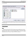
All the channels of our page are listed in the list situated on the left side of the window. We want
to make a fade between 2 positions, so we must enable the "FADE" function on Pan&Tilt channels for
all our fixtures. Please note that the function is already enable on Pan&Tilt channels...however this is
good to see how to do it. Now it is time to create our 2 scenes. In the previous chapter we saw how to
create a scene "As you see now"...we will use the same function and create the scenes using the TAKE
buttons.
Page 68
Compu Live
IV Advanced programming
Once the "Fade" function has been selected, we can setup the fade times. Please keep in mind
that the channels can have their levels increasing (Fade In) or decreasing (Fade Out):
- Time before fade In : Time between the call of the scene and the beginning of the Fade In
- Time of Fade In : Fade In time
- Time before fade Out : Time between the call of the scene and the beginning of the Fade Out
- Time of Fade Out : Fade Out time
Here, we can leave the default settings which are 5 seconds for the Fade In/Out times and no time
before Fade In/Out. We can click on OK when it is finished and our first scene is now ready to be used.
Let us create the 2nd one and call it "Scene 2". To do so, we release all the buttons in our page (double
click on INIT) and we call the "Scene 1". Then we use the TAKE buttons to setup a different position for
each fixture and we save the scene with the "As you see now function". Now we just have to setup the
Fade times (as we did with the 1st one) and we are ready to fade from our "Scene 1" to our "Scene 2".
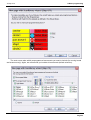
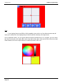
When a fade is running, the following window appears and shows you the FADE IN (left, red)
and the FADE OUT (right, blue). This window allows to make a break, to increase the speed of the
fade, to jump to the end of the fade or to go back to the beginning. Please note that you can make this
window visible or not by clicking on "Fade" from the "Windows" menu.
Page 69
Compu Live
IV Advanced programming
Please keep in mind that the FADE function is not available on channels which have been
programmed with the ON/OFF mode. This is very useful to make some channels fading or not in
a scene. Imagine you want to fade from one position to another one with your fixtures but you
want to change the gobo without fading in the same scene. The gobo channel must be
programmed with the ON/OFF mode, or the FADE function (Page Settings window) must be
disable on this channel.
4. External trigerring
Page 70
Compu Live
IV Advanced programming
4.1. MIDI - Easy Console
4.1.1. EasyConsole, what is it ?
EasyConsole is a new powerful tool for LIVE control. It allows users to connect any MIDI
controller to the software and assign numerous features to it. It is possible to control the speed or size
of a sequence, jump from page to page, select a particular button, freeze all DMX channels... and many
others. Once your show has been programmed with the software, it is very easy to assign it to the MIDI
controller's faders and buttons. This is an incredibly powerful tool that will both save users time and
allow a more precise control during "Live" applications. The following image is an example of a MIDI
controller with rotating buttons and faders, all of which can be perfectly assigned to work with our
software.
Page 71
Compu Live
IV Advanced programming
4.1.2. First, setup your controller on screen
The first thing you want to do is draw your MIDI controller on your screen, which will simplify its
use within the software. To make this work, a simple white square with faders and buttons can be
enough. However, you can make the screen representation of your controller closer to reality by pasting
pictures of it. The EasyConsole tool allows you to do that. You will be able to draw your controller and
then use it with Compu Live in just a few minutes.
Defining the background and adding images
It is very easy to create an accurate screen controller following a picture of an actual MIDI board. The
associated picture must be located in the "CSL" directory of the installation folder, in BMP format. The
"Bitmap" section of the "Properties" window allows you to select an image from this "CSL" folder, which
you can use as a background to create an accurate representation of your MIDI controller. If you wish
to add an image to your controller, select the "Picture control" tool and insert a new picture. Then, you
will be able to resize this picture, change its position, or even replace it using the 'Properties" window.
Defining the controls : buttons, faders...
Page 72
Compu Live
IV Advanced programming
There are 4 types of controls available : horizontal and vertical sliders, rotating and regular buttons.
These controls are available from the "Toolbox" window. Select the desired control from the toolbox and
then click on your project to insert a new control. Using the "Properties" window you can, for example,
move, resize or change the background image. You can also write labels on any control to clearly see
its function within the Compu Live software.
Defining the presets
4.1.3. How to use EasyConsole
First of all, make sure that the MIDI function is enabled in the starting parameters window. Open
the window from the "Controller" menu and go the the "Audio/Midi" tab to activate the function.
Page 73
Compu Live
IV Advanced programming
Assigning the MIDI controller to the software is very simple. Each button or fader must be
assigned independently. There are two ways to assign to assign a button: the regular and the quick
method.
Regular method
Page 74
Compu Live
IV Advanced programming
Once this window is opened and if the "Auto setup MIDI" option is activated, turn on the
corresponding fader or button on your controller and it will be automatically assigned. Repeat the
operation for all controls. Do not forget to save the configuration by clicking with the right button of the
mouse on the title bar and selecting "Save" from the menu.
These are not new functions and are explained in numerous chapters throughout this manual.
You can control functions like SPEED, DIMMER or SIZE of your effects. You can also select pages or
buttons, freeze the outputs, assign the DMX outputs to one or several faders of your controller in order
to have a general master fader, for example. Do not forget to save your modifications. This is not done
Page 75
Compu Live
IV Advanced programming
automatically.
Quick method
This is method is really faster and enables to setup 80% of the available features.
Imagine now you want to assign a scene or a switch to a button of the MIDI controller, a
blackout button for instance. Use the shift-click function (hold the shift key and click with the right button
of the mouse) on the switch and select "Button activation" from the "Link to Midi Controller" option. This
will open the following window, 4 options are available:
- On/Off: the switch is called when the MIDI command is sent
- V>Level: specify the minimum MIDI command level to call the switch
Level: specify the minimum MIDI command level to call the switch
- V- level1
Page 76
Compu Live
IV Advanced programming
4.2. MIDI - Midi Time Code (MTC)
MIDI TIME CODE input is useful to synchronize a cycle with an incoming MIDI TIME CODE
signal. In this case the software is said to be "Slave" and the external system "Master". The
signal can be generated by a CD/DVD player, an SMPTE generator, a 3rd party software (sound,
video, laser...).
For such use, make sure :
- your computer is equipped with a MIDI card (usually included in sound card) or a USB-MIDI interface
- to activate "MIDI IN" function in the "Audio/Midi" section of the "Starting parameters" (from the
"Controller" menu)
- to activate "TIME CODE IN" in "Synchro" section of "Page - Settings" window
Once all the settings are over, it will be possible to synchronize with MIDI TIME CODE input all the
cycles in the corresponding page (one at a time). A small button "MTC IN" appears in the Cycle
windows to disable/enable the function as shown in the picture below.
N.B.
Incoming MIDI TIME CODE can also be activated while creating a cycle. Timing will then be
automatically computed on MIDI TIME CODE.
Page 77
Compu Live
IV Advanced programming
4.3. DMX
Several functions can be triggered by DMX input channels on the user screen. You can start a
button (scene, switch or cycle), control the SPEED and DIMMER faders...
Buttons triggering
Faders control
Page 78
Compu Live
IV Advanced programming
Now, you can modify the dimmer of your page in real time with your external DMX controller.
This option may not be available with your version of the sofware.
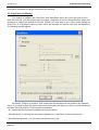
4.4. Clock and Calendar
The sofware can be triggered by Time (PC clock and calendar). This feature is available only in
Pro version and is very useful for architectural lighting. You must open the following window to setup
time triggering ("Button" menu, then "Settings"). The button you want to trigger must be selected before
to open this window!
Page 79
Compu Live
IV Advanced programming
First of all, we must click on "Enable" to modifiy the settings. Several options are available to
trigger a button (scene, switch or cycle):
Appointed time
Select what time you want to start your button.
Repeating time slot
Imagine you want to start the same sequence every 30 minutes from 10 am to 3 pm. You must setup
10H00 in the "From" box, then 15H00 in the "to" box and finally 0H30 in the "Repetition" box.
Unsettled time (Sunset)
Imagine you want to start a cycle every day following the sunset. You must use this option to do so.
First, select the "Date1" (first day) and the "Date2" (last day). Imagine you want to start your sequence
at 15H00 the first day and at 21H00 the last day, you must setup 15H00 in the "Time1" box and 21H00
in the "Time2" box. The software will calculate the time for every day...
Do not forget to specify UP or DOWN. UP means that the triggering time will increase every day (until
the "Time2"), DOWN means it will decrease...
Page 80
Compu Live
IV Advanced programming
4.5. Contact closure
A 10-pin connector is available on the USB-DMX interface and makes possible to send 8
different contacts to the software. The reference of the connector is HE 10 (male). You don't need to
send any power to the connector. You only have to create a contact between the pin 2 (ground) and the
other 8 pins (please note that the pin 10 is not used). Several things can be triggered by ports.
Buttons triggering
Cycles triggering
It is possible to trigger the playback function of the cycles in a page. To do that we must open the "Page
Settings..." window and go to the "Trigger" tab. Several options are available : play and stop the current
cycle, jump to previous and next steps...
Page 81
Compu Live
IV Advanced programming
Note: If the "ONLY" option is selected, all settings will work on the cycle called "SYNCHRO".
You can find more informations about the connection of DMX interfaces by reading the hardware
manual.
This option may not be available with your version of the sofware.
Page 82
Compu Live
IV Advanced programming
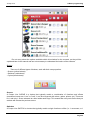
4.6. Audio Analysis
The Audio Analysis program allows to read and analyze a sound data through a sound card or
straight through computer files (CD, WAV files...). Tempo and BPM can thus be picked out.
Bass, medium and treble filters are made available in the SOUND TO LIGHT tab.
When Audio Analysis program operates as background task, the following icon appears on the
Windows toolbar.
By double-clicking this icon you may open the complete window so as to modify parameters
included in BPM and SOUND TO LIGHT tabs. Let us have a closer look at both of these features :
BPM
Page 83
Compu Live
Sound to Light
The following window appears on screen:
Page 84
IV Advanced programming
Compu Live
IV Advanced programming
The three filters may be personalized independently.
5. Page settings
The PAGE SETTINGS window contains all global options for each page. It is important to understand
the different options available. Simple options like buttons size and font can be customized, and
advanced otions as well: patch, compression (buttons arrangement), triggering, channels and fixture
options, etc...
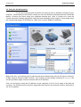
General
In the "General" section, you can basically do 2 things:
1. Change the DMX Universe for your page, which means shift the addressing by increments of 512
channels
2. Add a Background Image to the Fixture-Group window; this will allow you to take a picture of your
real stage and then place the icons for each fixture over the picture in the appropriate place
Page 85
Compu Live
IV Advanced programming
Channels
The "Channels" section allows you to change the properties of individual fixtures using the buttons on
the top. Starting from the left:
1. Insert fixture; you can insert a new fixture into a page that has already been created
2. Delete fixture
3. Set shortcuts; these shortcuts allow you to quickly access the channels for each fixture inside the
Button Editor
4. Advanced shortcuts; here you can set the same shortcut for different fixtures, as well as invert the
mouse's X and Y inside the Button Editor
5. X/Y; you can invert the pan/tilt channels for each fixture (symmetric movement), and you can also
limit the maximum pan/tilt (prevent light from hitting walls, people, etc)
6. Change address; change the patch for a fixture's starting address
7. Update the library/profile of the selected fixture
Page 86
Compu Live
IV Advanced programming
Buttons
The "Button" section allows you to define the font and size of the buttons on your page. This is very
useful if you need larger buttons because you have a very small screen, because you are using a
touchscreen monitor, etc...
Page 87
Compu Live
IV Advanced programming
Compression
The "Compression" section allows you to create or modify the groups of buttons within your page.
Notice how all COLOR, GOBO, PRISM icons are grouped together in your pages. When you create a
new Compression group, all buttons whose name starts with those same letters as the name of the
group will be linked together. For example, COLOR RED, COLOR BLUE, COLOR YELLOW, COLOR
WHITE can all be compressed under the group named COLOR.
You cannot group Scenes, Switches, and Cycles together, so you must define what type of button the
compression group will work with. Finally, you can set the Compression type.
Synchro
The "Synchro" section allows you to synchronize your Cycle buttons within the page in a number of
different ways.
Page 88
Compu Live
IV Advanced programming
Trigger
Keep in mind that these features act on he current page only and can be assigned differently in
other pages.
Some specific features can be triggered either by the computer mouse, shortcut keys, DMX input
channels...
For instance, it is possible to start a cycle, stop it, go to the next scene...this is a very important feature
for theatre applications. There is always the possibility to play/pause/stop a cycle with a simple action
and makes it very powerful and easy to use.
For example, if we wanted to play the selected cycle with the SPACE bar, we would have to select "[6]
Play the current cycle" feature and activate the "Key" control before selecting the SPACE bar from the
pull-down menu, as shown in the picture above.
Page 89
Compu Live
IV Advanced programming
Advanced
The "Advanced" section allows you to assign MIDI commands to a different properties within the page.
Notice that the 2006 software allows right-clicking from the controller page and do a simple LINK TO
MIDI devices (see "Console" section in Advanced Programming).
Page 90
Compu Live
IV Advanced programming
Groups
The "Groups" section allows you to see a table with all your fixture groups within the page and their
assigned shortcut keys. You can modify or add groups from this window by right-clicking on it.
Options
Finally, the "Options" section provides a couple more properties that can be modified within each page.
Page 91
Compu Live
V General settings
V General settings
1. Starting parameters
The software has several global parameters (ethernet, audio, midi, outputs...) that are loaded at
startup. These settings can be modified by the user with the "Starting parameters" window. To open it,
go to the "Controller" menu and select "Starting parameters".
3 sections are available: Hardware, Options and Other. Here is a description of the different settings
available:
Outputs
The sofware can control up to 50 universes simultaneously depending on the version. This section
enables to patch these universes to the outputs (USB-DMX interface, IP_DMX or ethernet). Every
universe has to be linked to a single output. If you wnat to control your lights (2048 channels) with the
Art-Net protocol, you should have to specify universe #1 on PC-Ethernet 1 output, universe #2 on
PC-Ethernet 2 and so on...
DMX inputs
It is possible to connect any DMX controller to the software (depening on the version) to control some
features like SPEED, DIMMER, to start buttons or to record a sequence. 10 universes can be linked to
the sofware and must be patched in this section.
Ethernet network
The SLNETWORK feature enables to control DMX interfaces that are connecte to another computer in
the same network. This function must be enabled in this section by selecting the "Activate Network
facility" option. There is also the possibility to setup the IP address of the "slave" computer.
Protections
It is possible to enable some feature of the software or not and to protect them with a password. For
instance, this can be used in a club to have le light jockey only use the program without deleting or
programming anything. Several levels are available but you can also select the custom level and
specify which are the available functions.
Beginner mode
The sofware can be run in 2 modes: advanced and beginner. In this section, sofware restrictions can be
setup for the beginner mode. Many options (windows management, menus...) or functions (buttons
editing, cycle recording...) can be disable for the beginner mode.
Audio/Midi
Page 92
Compu Live
V General settings
To use the audio (audio analysis) and midi triggering (Easy Console, MTC...), several options must be
selected in this section. The 1st option enables to read the audio signal from the sound card, the 2nd
one enables to read MIDI informations and the last one to send MIDI informations to another device.
Pages priority
Here we can setup the priority level between the MASTER page and the sub pages. There are 3 levels:
- LTP (the last action takes the priority)
- MASTER (the MASTER page has always the priority)
- Sub pages (the sub pages always have the priority)
Color settings
Here we can define the colors for the buttons (scenes, switches, cycles).
Follow spot
The follow spot function enables to create a follow spot with moving heads or scanners. A master must
be selected and the slaves will follow the same point while it is moving. The sofware must learn the
stahe dimension and the fixtures positions for this function. This is possible by recording points on the
stage. The more points you record the more efficient is the follow spot. Here we can define how many
points have to be recorded, the default value is 25 (5*5).
Reset 3D - Reset SLMM
2. Windows management
The sofware offers the possibility to split the screen in several windows: pages, outputs, cycles,
groups...Every user can customize the positions and make it easier to use or understand. It is possible
to display or not some windows, to change their positions (tabs, splitted...) or to resize them.
One important thing is the "Reset positions" function (Windows menu), that enables to get back to
default positions if you can not find a window any more. Two options are available: reset to default or to
tab positions. There is also the possibility to lock the screen. We recommend to use this function to
avoid unattended "bad actions"...
Let us see how to arrange the windows and customize the screen.
Tabs positionning enables to save place on the screen. It allows to have a quick access to several
windows and have them displayed in a larger size than if the screen was splitted. The picture below
shows how to modify the position of a window.
Moving a window requires to click on the title bar of the window and hold the button pressed while
moving the window. The sofware shows a blue area that represents the actual position and size of the
window.
Page 93
Compu Live
V General settings
To software helps to find the correct position with the following tool. Moving the mouse on it
enales to create to create a new tab or split the screen vertically or horizontally. The icon in the centre
creates the tab and the other 4 icons split the window.
Page 94
Compu Live
V General settings
3. Backup /Technical support
If you ever experience any difficulties with the sofware, there is the possibility to send a complte
backup to our technical support. Select full backup from the "?" menu and it opens the following
window.
There is also the possibility to send an email to the technical support by clicking on "Email" from
the "?" menu or to post a message on our Internet forum at www.elationlighting.com/forum
Page 95
Compu Live
V General settings
4. Setting up multiple DMX universes
The software can control up to 50 DMX universes simultaneously. The different universes can be sent
with our electronic interfaces (USB or IP) or with the ethernet connector of the computer (Art-Net
protocol). It is important to understand how to setup the multiple universes in order to send the DMX
information to the correct output. We will see in the following chapter how to setup and use multiple
DMX universes with your software.
4.1. Using the USB interfaces
Compu Live can operate up to 10 USB-DMX interfaces simultaneously. Then, it is possible to run 10
DMX universes with single output interfaces and 20 universes with new IN/OUT interfaces. We will see
later how to convert the DMX IN connector of your interface in a second DMX output.
You must open the "Starting parameters" window and the "Output" tab to setup the universes. You will
have to select "USB-DMX" for all universes you want to control with your interfaces.
Do not forget that if a universe is not correctly assigned to a output hardware, you might not be
able to control your lights with it.
Use of the DMX IN connector as a second output
It is possible to convert the Input connector of your interface in a second output. To do that, you must
open the "Starting parameters" window and the "Output" tab. Then, imagine you want to use the
software universes #1 and #2 with your USB interface, you will have to select "USB-DMX" for the 1st
universe and then check the box located on the right side of the list. You can now select "USB-DMX (Out2)" for the universe #2.
Do not forget to purchase or make a female to female XLR converter to connect your lights.
Page 96
Compu Live
V General settings
4.2. Using the IP interfaces
To use the IP interface you must first make sure that your IP interface is connected and configured
correctly, and recognized by the network and the computer which will control your lights. Refer to the
Appendix "IP/Ethernet configuration" for detailed instructions on how to do this. Then, in Compu Live,
under the "controller" tab, open the "Starting parameters"; then under "hardware" select "output." Here
you can select each DMX universe and assign it to a particular interface output. For the IP interface,
you must select your universe, then click next to "PC-Ethernet" and a drop-down menu will appear.
Scroll to IP_DMX(***.***.*.**) to select this particular IP interface. [Note-Each IP interface will have a
unique IP addres that will apear in the parentheses). Click OK, now your universe is assigned to the IP
interface
Page 97
Compu Live
Page 98
V General settings
Compu Live
V General settings
4.3. Using the Art-Net protocol
To use the Art-Net protocol first make sure that you have an interface connected to your
computer. Art-Net protocol will not work unless you have an interface connected which will unlock this
feature. Connect your fixture using your computers ethernet port. Now, in Compu Live, under the
"control" tab select "starting parameters" and then under hardware select "outputs." Now simply select
the universe and assign it to PC-Ethernet. Make sure to check "Enable PC-Ethernet."
Most of the time, your fixtures won't be able to read the Art-Net protocol and you will have to convert it
to DMX using an Art-Net to DMX converter. They ususally convert multiple universes (2, 4, 6, 8...). We
can also provide a single universe converter with our IP interface.
Then, do not forget to setup the IP address of your computer on the 2.X.X.X range to talk with the
converter. The Art-Net protocol uses this range and both converter and controller must be setup with a
2.X.X.X IP address.
Page 99
Compu Live
VI Appendix
VI Appendix
1. DMX512 brief description
By the time you are done reading this section, you will understand how DMX works and why the
lighting world uses this standard communication protocol. For a more technical and detailed description,
please visit www.dmx512-online.com
1. The need for a standard
About 20 years ago, most lighting and console manufacturers had their own proprietary communication
protocols. During installations, it was necessary to use all lighting fixtures from the same manufacturer,
of course with their own controller board. If you wanted to use lighting fixtures from different
manufacturers (even simple dimmers), each group required their own lighting desk. It is clear that a
standard form of communication between controllers and the fixtures was necessary.
2. Understanding DMX
To understand the DMX512 communication protocol (commonly referred to as “DMX”), we will
use the “Cable TV” analogy.
Imagine a simplistic cable TV system, with only 4 relevant parts:
a. TV station
b. cable
c. decoder
d. TV set
The TV station broadcasts a signal that travels through a cable network until it reaches a decoder. The
decoder receives information on hundreds of channels, but only displays on the TV set the information
(in this case video and audio) from that single channel that we select. The TV set ignores the
information from any channel that is not selected. It only displays the information from the channel
selected in the decoder.
DMX can be related to this cable TV system, where:
a. the TV station is the controller (Compu Live)
b. the cable is a DMX cable
c. the cable decoder is the DMX decoder (which usually is inside each lighting fixture)
d. the TV set is the lighting fixture
In DMX, the number of channels that are broadcasted is always 512. Maybe some of them will be
empty or unused, but they are still broadcasted because it is a necessary component of the standard.
So, the controller sends out a signal (512 channels of information), which travels through a DMX cable
until it reaches the decoder inside the lighting fixture. In the same way you set the channel you want to
Page 100
Compu Live
VI Appendix
watch on your TV, in a lighting fixture you set the channel that you want your fixture to display the
information for. This is known as the DMX address.
In other words, if I set my lighting fixture to channel 21, then my fixture’s DMX address is 21. Both
expressions are common in the lighting world.
Example
Imagine we have a DMX dimmer that controls a simple light bulb. This dimmer is set to DMX address
21, so the lighting fixture will only receive the information from channel 21 and ignore the rest.
We have a controller that sends a signal through a DMX cable and this cable goes into a decoder (the
DMX dimmer) that receives the signal. So if the controller sends the “turn on” information on channel
21, the dimmer will turn on the light bulb.
Conventional lighting fixtures (simple dimmers) require 1 channel of information only. However,
intelligent lighting fixtures require more than 1 channel to work. For example, if I have a lighting fixture
that requires 5 channels of information, and its DMX address is 21 (again, address is the first channel
used by the fixture), then this fixture will use channels 21, 22, 23, 24, 25. The decoder knows that the
fixture needs 5 channels of information, so it will decode 5 channels only and ignore the rest. The
controller knows the fixture uses 5 channels also, so it will send 5 channels of information.
Example
Imagine you have a very simple robotic moving head that uses 5 channels:
1. pan
2. tilt
3. color wheel
4. gobo wheel
5. dimmer
You set your moving head to address 21 and you tell the controller that you have this particular moving
head on address 21. The controller then knows that channel 23 corresponds to color wheel, for
example. If you want to change the color of the light beam, you tell the controller what color you want,
the controller automatically sends this information through channel 23, and the lighting fixture reacts
accordingly.
Typically, intelligent lighting fixtures use 1 channel (sometimes more) for every function they can
perform (color, gobo, prism, dimmer, etc). Some robotic moving heads use over 20 channels, some
simple scanners only 4 channels, etc.
3. The protocol
So far, we’ve been referring to “information” traveling through DMX cables from the controller
into the fixture’s decoder. This “information” is nothing but a number between 0 and 255. This number is
called the DMX value for a particular channel. Then, the DMX signal is nothing but a series of DMX
values along 512 DMX channels.
Example
Back to our 5 channel simple robotic moving head; channel 3 controls the color wheel, which has 25
different color combinations. The color displayed will depend on the DMX value on channel 3 (as it is
being sent by the controller) as follows:
Page 101
Compu Live
VI Appendix
0-10 White
11-20 Red
21-30 Purple
…
241-255 “whatever color”
So, if the lighting fixture receives a DMX value of 25 for Channel 3, it will display the Purple color. If that
DMX value changes to 15, it will automatically change to Red, and so on.
Luckily for us, the Compu Live software (and most controllers) includes profiles for these lighting
fixtures. These profiles contain all the DMX values and channel information required to have full control
of the lighting fixture. Typically, all you will need to do is set the DMX addresses right, and the controller
will make everything else easy (some controllers are easier to use and learn than others, but that is the
overall idea).
When a lighting fixture is manufactured, a DMX chart is provided in the user’s manual. This DMX chart
contains all the information that controller manufacturers need to create these profiles. Most controllers
include only the most popular fixtures in their particular market. We can proudly say that Compu Live
(and our OEM partners) are the only controllers with over 2,000 different profiles from manufacturers
from all around the world, so no matter where you purchased your lighting equipment, chances are we
will have profiles for it, which will allow you to control them without a problem.
4. Compu Live Importance
Summarizing, most lighting fixtures and their controllers communicate using a protocol called
DMX-512 (for a very detailed description of DMX history and technical specs, please visit
www.dmx512-online.com).
Important about DMX and lighting fixtures:
1. Lighting fixtures use 1 separate channel to control every function they can perform (one channel to
control colors, another for gobos, another for dimmer, another for shutter, etc)
2. You can use a maximum of 512 channels for every DMX line
3. There is a value from 0 to 255 assigned to every DMX channel
Important about Compu Live and lighting fixtures:
1. When you tell your Compu Live controller what kind of lighting fixtures you are using, Compu Live will
know exactly how your fixtures work and what DMX distribution they have.
2. This allows Compu Live to show preprogrammed buttons on the screen corresponding to every
function that the lighting fixture can perform (1 button for white color, a different button for red, 1 button
for every gobo, for every macro, etc).
3. To begin programming lighting effects using Compu Live, all you need to do is click on
preprogrammed buttons!
4. Because of its visual interface and simplicity to program, thousands of users worldwide have chosen
Compu Live as their preferred lighting controller
Page 102
Compu Live
VI Appendix
2. Accessories
The following is a list of accessories that can be used along with our software and interfaces. It is not a
comprehensive list, but it should give you a good idea of where to start looking.
IO Ports and Power Supplies
Jameco (USA)
112547CH Multicolor Ribbon Cable
32491CH Socket Connector
252793CH Power Adapter
Keypads
Search online for “8 key common” or “12 key common”. You can use any custom built switch, given that
you only need to make simple contact closures… even a paper clip could do the trick, if you wanted.
www.designnotes.com
www.allelectronics.com
Relay boards
The IO ports can be closed manually using keypads and switches, or remotely using relays. The
advantage of using relays is that you can have any human interface with the Compu Live software
working in the background. Some of these relays can be activated via InfraRed remote controls, for
instance.
www.rentron.com
www.dataprobe.com
www.quasarelectronics.com
MIDI controllers
The Compu Live software can work with ANY MIDI device. Here is a list of the most popular:
- Evolution UC-33
- Behringer BCF2000
Page 103
Compu Live
VI Appendix
You can search online for these names and compare pricing and features.
DMX Boards
The Compu Live software can take input commands from DMX boards. Any button on the Compu Live
screen can be triggered through DMX, and also any fader can be linked to a DMX fader on a board.
The following sites will give you an idea of where to start looking:
www.proformance.net
DMX Dimmer Packs
Conventional lighting can be controlled through DMX if these fixtures are connected to what are known
as Dimmer Packs. There are many manufacturers out there.
www.proformance.net
3. IP/Ethernet configuration
Our Ethernet interfaces come with a factory IP address 192.168.1.20. An IP address is a number that is
unique to any particular device within a network. In order to communicate with your interface, you need
to manually set your computer’s IP address to 192.168.1.xx, where “xx” is any number other than 20.
You cannot have both devices (interface and computer) with the exact same IP address, but both need
to be within the same subnet (192.168.1.xx).
To configure your computer to work with our Ethernet interface:
1. Connect your IP/Ethernet interface to your computer and to its power supply (9-12V DC).
2. Change your computer’s IP address to match the interface's subnet mask. Start from Window’s
Control Panel, then Network Connections. Double-click on the Local Area Network connection, then
click on TCP/IP, then Properties. Change from “Automatic” to “Use the following” IP address, and type:
IP 192.168.1.xx (xx is any number larger than 10, different from 20)
Subnet mask 255.255.255.0
Leave all other fields blank, then click OK. Wait a few moments while the connection is reset between
the interface and computer. Close the Local Area Network properties window.
3. Start the Compu Live software.
Page 104
Compu Live
VI Appendix
Once the software is open, go to the “?” menu, then About. A circular popup with the logo will be shown
with a white box underneath. In this box, you should read something like this:
Compu Live
June 13 2006(Release date)
1 SLESA-IP (interface description in red letters)
If you can read this interface description, this means that there is good communication between the
software and the interface... you are done!
If you cannot read the interface description, this means you probably purchased a simple IP-DMX
converter and forgot to also connect the USB interface for the software.
If you go into the CONTROLLER menu, then STARTING PARAMETERS, you will be able to set the
universe for each USB-DMX or IP-DMX interface.
Changing the IP address of the interface
If you wish to change the IP address for the Ethernet interface (default 192.168.1.20), you need to do
this from the
Stand Alone
software (included in the installation CD). Connect the interface directly to your computer using the
cross-over Ethernet cable provided, and set your computer's IP interface within the same subnet as the
interface (192.168.1.xx).
Start the Stand Alone software. Go to the TOOLS menu, then IP/ETHERNET OPTIONS. The password
is
JULS
In that window you will find LAN settings. Make all desired changes and close the Stand Alone
software. Disconnect the interface from your computer and using a regular Ethernet cable (not
provided) connect the interface to your network router. When you start the Compu Live software, you
should see the same red description for the interface as you did when they were connected directly.
Page 105
Compu Live
VI Appendix
4. Troubleshooting
Software and/or interface do not work
1. Check the USB interface
Connect the interface to the computer. You should see 3 LEDs turn on, green, yellow, and red. Green
should be blinking slowly. Yellow should be completely on. Red should be blinking fast.
If non of the LEDs are on, check the back of the interface, there is a small switch that turns power
ON/OFF. If only the yellow LED is on, then your interface is broken, please contact your retailer to have
it replaced.
2. Check software/interface communication
Connect the interface to the computer BEFORE you start Compu Live. After you open the software, the
green LED should start blinking fast. If you go to the “?” menu, then “About”, a circular popup will
appear with our logo in it. Underneath you will see a white box with the software name and release
date. If there is good communication between the software and the interface, you should see a
description of your interface in red letters inside this box as well.
If the green LED is not blinking fast, or you do not see the red letter description, there is no
communication between the software and the interface. You probably did not install the drivers
correctly.
3. Check the interface drivers
If you are using Windows XP, reconnect your interface to any USB port (a different one, if possible).
Windows will tell you whether the hardware found is new or already installed in your computer.
If it is new, the NEW HARDWARE WIZARD window will appear. Insert the installation CD in your
computer, and select Automatic Search (if you do not have the installation CD, go to the
Support/Downloads section in our website). Click “Continue Anyway” when Windows asks you about
verification.
After this, Windows should tell you that your device is ready to be used. Restart the Compu Live
software and check communication (previous step).
4. Double-check interface drivers
If during the installation of the drivers, when asked about Windows verification and compatibility, you
selected "Stop installation" instead of "Continue anyway", the drivers will not be installed correctly.
To check if the drivers were installed correctly, you should go into
- Windows Control Panel - System - Hardware - Device Manager
You will see a list that includes all USB devices. If the interface is connected and the drivers are
installed correctly, the name of the device will be "Intelligent Usb Dmx Interface". If, on the contrary, you
read "Unknown device" with a yellow exclamation point next to it, the drivers are not installed correctly.
To fix this:
- Uninstall unknown device
- Disconnect USB interface, wait a couple seconds, and reconnect
- The "Add New Hardware Wizard" will appear, just follow the instructions (previous step)
- Make sure you select "Continue anyway" when asked about Windows verification and compatibility
5. Test on a different computer
If nothing seems to work, please try testing on a different PC before contacting your retailer to get an
exchange. Typically, you should only ask for an exchange if:
- No LEDs turn on, even when you have moved the power switch in the back of the interface
- Only the yellow LED turns on
Page 106
Compu Live
VI Appendix
- The drivers seem to be installed correctly, but the interface/software does not work, and the Device
Manager name for the USB device is "SUIDI-OUT" instead of "Intelligent Usb Dmx Interface"
Scenes/Switches do not work
If you find problems using your scene and switch buttons, check for the following common solutions:
1. Deactivate all buttons
Double-click on the [INIT] scene in each page, all buttons should be deactivated. Then start using your
buttons from zero and find which button brings the problem at hand.
2. Disable LIVE mode
If you are using the LIVE mode in the FIXTURES-GROUP tool to control fixtures individually within
each page, you will not be able to deactivate switches. This could seem like the actual Switches are not
working. All you need to do is make sure the LIVE mode feature is disabled, then everything will be
back to normal.
3. [AUTO] DMX output window
At the bottom of your screen, you can see the DMX output for the controller. You can force a channel to
have a particular output from this window, apart from the signal coming from your scenes and switches.
If your buttons don't seem to work, make sure all channels have the AUTO property assigned
(right-click at the base of the channel to change this property).
I cannot find my pages
If some of your page windows "disappeared" from your screen, simply go to
- Windows menu - Reset Positions - Reset to tabs
You can also read "Windows Positioning" under the General Settings chapter for more information.
Fixtures going crazy
1. DMX addresses
Make sure the addresses for your lighting fixtures are the same as those defined within the software
controller. You can check the addresses in the controller from the PAGE menu, then SETTINGS, then
CHANNELS.
2. Fixture profiles/libraries
Sometimes fixtures have different "modes" that increase the number of channels or swap them around.
Make sure you are using the right profile for your fixtures.
3. DMX cable
If you are still having problems, try using a different cable (make sure it is a good one).
Page 107
Compu Live
VI Appendix
5. Commands summary
User's screen
FEATURES
Creating a new page
Open archive
Save archive
Freeze channel
Short channel level setting
Enable a manual fading
Activate or de-activate fixtures 3D
representation (3D software)
SPEED (-) (master)
SPEED (+) (master)
DIMMER (-) (master)
DIMMER (+) (master)
Master SPEED reset
Master DIMMER reset
Select button
Delete button
Button settings
Edit
Delete shortcut
Implement new shortcut
Assign a MIDI shortcut (display MIDI
activation)
Assign a PORT shortcut (display
PORT activation)
Assign a DMX shortcut (display
DMX activation)
Move a button (if enabled on
"button" toolbar)
SPEED (-) (of selected button)
SPEED (+) (of selected button)
DIMMER (-) (of selected button)
DIMMER (+) (of selected button)
Display a scroll menu
Editor screen
Page 108
EQUIVALENT MENUS
"Page" "New page"
"Page" "Open archive..."
"Page" "Save archive..."
"Page" "'Live' Page toolbar"
"Freeze"
"Page" "'Live' Page toolbar""Set
levels"
"Page" "'Live' Page toolbar""Manual
fading"
"Page" "'Live' Page toolbar""Show
fixtures in the 3D software"
'Live' button toolbar
'Live' button toolbar
'Live' button toolbar
'Live' button toolbar
"Button" "Delete"
"Button" "Settings..."
"Button" "Edit"
SHORTCUTS
Alt+N
Alt+O
Alt+S
F12
F11
F10
F9
F3
F4
F1
F2
F1+F2
F3+F4
Shift+click
Alt+D
Alt+P
Alt+E ou Ctrl+click
Ctrl+Del
Ctrl+key
Ctrl+Note MIDI
Ctrl+Port
Ctrl+DMX
Shift+ right click
'Live' button toolbar
'Live' button toolbar
'Live' button toolbar
'Live' button toolbar
"Button"
F7
F8
F5
F6
Shift+ right click
Compu Live
FEATURES
Close and save
Close without saving
Channel-level display in DMX value
Channel-level display in %
No channel-level display
Visualize right hand part of the
channel-list
Visualize left hand part of the
channels list
Display preset-list
VI Appendix
EQUIVALENT MENUS
Adjust several similar type of
channels to the same value (e.g
Pan, Shutter,...)
SHORTCUTS
Alt+S
Alt+Q
Ctrl+D
Ctrl+P
Ctrl+N
RIGHT (pointer)
LEFT (pointer)
Right click on channel
name
Shift+click
Cycles
FEATURES
EQUIVALENT MENUS
GO forward
GO backward
Saving relative time in LIVE mode(if
cycle in PLAY mode)
Select next recording (if cycle in
STOP mode)
Select previous recording (if cycle in
STOP mode)
SHORTCUTS
Page Down
Page Up
END
DOWN (pointer)
UP (pointer)
Page 109
Table of contents
I Welcome to Compu Live
1. Installing software/interface
2. Demo shows
3. Adding your first fixture
4. Compu Live Overview
II Basic programming
1. Adding your own fixtures
2. Pages and Buttons
3. Preprogrammed buttons
4. Example: create your first scene
5. Record Cycles (cue lists/shows)
6. Keyboard triggering (hotkeys)
III Intermediate programming
1. EasyStep scenes
2. Channel properties: On/Off, Dimmer
3. Group/Individual control of fixtures
4. The X-Y window (pan/tilt)
5. Using the MASTER page
6. Controlling Speed/Size of your scenes
IV Advanced programming
1. Overview
2. The Editor
2.1. Easy Time
2.1.1. How to use Easy Time
2.1.2. How to use Easy Time for movement
2.1.3. Tools and options
2.2. Color Manager
2.3. Copy/Paste and Phasing
3. Fade between scenes
4. External trigerring
4.1. MIDI - Easy Console
4.1.1. EasyConsole, what is it ?
4.1.2. First, setup your controller on screen
4.1.3. How to use EasyConsole
4.2. MIDI - Midi Time Code (MTC)
4.3. DMX
4.4. Clock and Calendar
4.5. Contact closure
4.6. Audio Analysis
1
2
7
11
14
19
18
24
26
29
32
34
37
36
38
41
47
50
52
57
56
56
56
56
58
61
62
64
66
70
71
71
72
73
77
78
79
81
83
5. Page settings
85
V General settings
93
1. Starting parameters
2. Windows management
3. Backup /Technical support
4. Setting up multiple DMX universes
4.1. Using the USB interfaces
4.2. Using the IP interfaces
4.3. Using the Art-Net protocol
VI Appendix
1. DMX512 brief description
2. Accessories
3. IP/Ethernet configuration
4. Troubleshooting
5. Commands summary
92
93
95
96
96
97
99
101
100
103
104
106
108
Compu Live
I Welcome to Compu Live
I Welcome to Compu Live
Prologue
Thank you for your interest in the Compu Live control software.
Our User Manual is divided into the following chapters:
1. Welcome to Compu Live
Quick start guide, Overview
2. Basic Programming
3. Intermediate Programming
4. Advanced Programming
5. General Settings
Appendices
In this manual, the most elemental concepts of lighting control are presented early on, followed by
increasingly more complicated software tools and functions as the manual progresses. Though our
software is designed to be simple to use and intuitive to learn, we strongly recommend beginner users
to read this manual consecutively, starting from the first chapters and so on. Intermediate and
advanced programmers will usually skip through sections without a problem.
This first chapter gives users a quick overall look at our software (essential if you are impatient like
most of us). We will walk you through the installation process for the software and the interface drivers.
Then we will play around with our preprogrammed DEMO shows. At the end of this chapter, we will
quickly show you how to add your own fixtures into the software, just in case you cannot wait to test
your own lighting fixtures.
The second chapter will show you the most elemental programming tools within the software. By the
end of this chapter, you should be able to program a decent looking show very quickly.
The third and the fourth chapter describe more advanced (not necessarily complicated) software tools.
This knowledge, along with a little practice, will allow you to create almost any lighting scene/effect your
fixtures can handle.
The fourth chapter briefly describes peripheral software tools in the Compu Live package, such as the
3D visualizer (Easy View), a profile/library editor (Scanlibrary), a music/video/lighting timeline
synchronization tool (Easy Show), and downloading scenes/shows into the internal memory of the
electronic interface (Easy Stand Alone).
The fifth chapter include several starting parameters the user should be familiar with, options for the
windows management and Backup/Technical support
Finally, you will find appendices that include a DMX512 review, MIDI review, list of available
accessories, and a troubleshooting guide.
Page 1
Compu Live
I Welcome to Compu Live
1. Installing software/interface
1. Installing the software
Whether you are holding an installation CD in your hands or you downloaded the software from
the internet, the first thing you want to do is install our Compu Live software.
Insert the installation CD in your computer (if you downloaded the software from the internet,
you can skip this paragraph). Once the installation screen is open, select your language and click
NEXT,
then accept the license agreement, and finally click on the INSTALL icon for Compu Live.
Page 2
Compu Live
I Welcome to Compu Live
Select the Setup language and accept the license agreement (again). Choose your installation
folder (default is C:SL2006). The next screen will ask if you want to install the software with or without
DEMO PAGES. If you are a beginner user, we recommend you install WITH demo pages.
Page 3
Compu Live
I Welcome to Compu Live
Finally, the setup wizard will ask if you want to start the software in BEGINNER MODE. Again, if
you are a beginner user, we recommend you click YES on the beginner mode option.
You are done! Now, it is time to start playing with our software.
2. Installing USB drivers
If you purchased a software package and received a USB to DMX interface, you will need to install the
drivers for it. You can use the full software without the interface, but you will need this USB-DMX device
if you want to control real lighting fixtures.
Page 4
Compu Live
I Welcome to Compu Live
Windows will find the driver and will tell you the device is not validated, and will ask if you wish to
continue. Although Microsoft does not have a numberical registry for this driver, there is no risk of
incompatibility. Click "Continue Anyway".
Page 5
Compu Live
I Welcome to Compu Live
You are done! But remember, the software detects the USB interface when it starts. This means that
you must have the USB interface connected to your computer before you open the control software.
Otherwise, there will be no communication between the software and the interface.
3. Using IP/Ethernet interfaces
If you purchased a Compu Live package with an IP/Ethernet interface, please refer to the Appendix
section for instructions.
Page 6
Compu Live
I Welcome to Compu Live
2. Demo shows
For this section, we assume you installed the software in BEGINNER MODE and that you
enabled the installation of DEMO PAGES. If you did not, you will see many options on your screen
apart from the ones described here, but the information will still be valid.
Your screen should look like this:
The Compu Live software will display 1 button for every function that the lighting fixture can
perform. There will be 1 button on the screen for every color, gobo, macro, prism effect, etc.
Page 7
Compu Live
I Welcome to Compu Live
Depending on the type of intelligent lighting that you’re using, there will also be preprogrammed
buttons with generic effects (in this case, the DEMO MOVING HEAD page contains buttons with
movements that are generic to all moving heads and scanners, like circles, random curves, etc).
As you can see on the 3D visualizer window, every time you press a button on your screen the
moving heads respond to that command.
Page 8
Compu Live
I Welcome to Compu Live
Keep in mind that the 3D window is a real-time visualizer. This means that if you had those 4
moving heads connected to your computer, they would be doing that exact same thing you are seeing
on the screen.
Keep pressing any combination of buttons… play around. If you want to reset everything, double click
on the yellow INIT button. If you find a “look” or “effect” that you like, you can save it by going to:
Button menu – New Scene – As you see now – OK
Page 9
Compu Live
I Welcome to Compu Live
We recommend you create a few scenes like this, so that you get somewhat familiar with the
controls. Once you feel comfortable with the preprogrammed controls in the Demo Moving Head page,
you will be ready to add your own fixtures and learn more advanced programming techniques. We still
recommend, however, that you read this manual consecutively, and advise beginner users against
jumping in between chapters at this point.
Page 10
Compu Live
I Welcome to Compu Live
3. Adding your first fixture
If you already have an interface connected to the software and you cannot wait to test these
movements and effects on your own lighting fixtures (or if you want to preview how your own fixtures
would work), this is how you can add them to the Compu Live software:
Page menu – New page
Select "Create a new page with Scanlibrary wizard".
Page 11
Compu Live
I Welcome to Compu Live
You will be able to browse through the profile library in your computer. Search for your
manufacturer's folder and then your particular fixture (notice there is a VARIED folder where fixtures
from small manufacturers are included).
Page 12
Compu Live
I Welcome to Compu Live
After you find your lighting fixture in the manufacturer folders, you will need to set the starting
DMX address and number of fixtures (if you do not know the meaning of “starting DMX address”,
please read Appendix A “DMX Review” before you continue).
Then, simply click NEXT to all the options that the wizard presents (not important at the
moment, but will be explained in detail in later sections in the manual).
You’re done! Now you have 2 pages: the DEMO MOVING HEAD and your MANUFACTURER
FIXTURE. Assuming your lighting fixtures are connected and addressed correctly, everything shown in
the 3D visualizer should be simultaneously happening with your real lighting fixtures. If you think you
have everything setup correctly and are still having problems, please refer to Appendix D
“Troubleshooting”.
There you go! Keep reading the manual to learn how to program more elaborate lighting
scenes/shows/effects.
Page 13
Compu Live
I Welcome to Compu Live
4. Compu Live Overview
The following chapter will provide an Overview of the entire Compu Live package. The main
goal of this chapter is to give you a better idea of Compu Live’s full potential…
Easy View
Our real-time 3D visualizer, which will show you all of your lighting effects on your computer screen in
the same way they would look if your actual lighting fixtures were connected to the computer. Ideal to
pre-program without lighting fixtures. Create your own stages adding objects and textures, making them
as realistic as you want. Record videos of your lighting shows or take still pictures. Print 2D views from
your stage, including all your fixtures, trussing, furniture, etc.
Page 14
Compu Live
I Welcome to Compu Live
Easy Show
Ideal to synchronize lighting effects with audio and video. Similar to audio editing software, Easy
Show includes timelines where you can drag, drop, expand, scroll your lighting effects, along with Audio
and Video timelines.
Easy Stand Alone
Create your lighting scenes, then download them to the memory of the interface. Depending on
the number of lighting fixtures that you’re using, you can have hundreds, even thousands of scenes
recorded in our small electronic interface. Trigger lighting shows at scheduled times using the
interface’s internal clock and calendar. Activate lighting scenes using simple IO contact closures.
Page 15
Compu Live
I Welcome to Compu Live
Scanlibrary Editor
Create your own profiles or modify existing profiles for lighting fixtures. All effects are included
(color, gobo, gobo rotation, prism, etc). Preview your profiles using our 3D visualizer.
Page 16
Compu Live
I Welcome to Compu Live
Page 17
Compu Live
II Basic programming
II Basic programming
Overview
After reading our "Welcome" chapter, you might have a good idea of what you would like to
accomplish with our Compu Live controller. Now it is time to learn how to create all those lighting
scenes you have in your mind already.
This chapter explores the options available when adding your own fixtures through our “New Page
Wizard”. Then we focus on available preprogrammed buttons for all intelligent lighting. We look deeper
into the “New Scene – As you see now” option. Finally, this chapter explores the triggering of lighting
scenes from your computer's keyboard.
1. Adding your own fixtures
Whether you purchased the electronic interface already or simply downloaded the free software
from the internet, you probably have an idea of what type of lighting fixtures you want to control. The
Compu Live includes a library of about 2,000 profiles from lighting manufacturers from around the
world; most likely your lighting fixtures are included.
Fixtures are grouped inside the Compu Live software into "Pages". Thus, to add your own fixtures, go
to:
Page menu – New page
Page 18
Compu Live
II Basic programming
You can see two buttons. The first "Create a new page with Scanlibrary wizard" opens our
profile library. The second "Create a blank page", adds an empty page of DMX channels in the software
(configuration for these blank pages is described in later chapters).
The first "Explore" button allows you to search the library of profiles installed in your computer
along with the software. The second "Explore" button is a link to our online library.
We recommend you look for your profiles within your computer first, and if you can't find them, then go
online. The third button opens the Scanlibrary Editor. This is an aditional software tool that allows you to
construct or modify your own profiles. Please read the "Scanlibrary Editor" manual for more information
on how to create personalized profiles.
Page 19
Compu Live
II Basic programming
Note: If you cannot find your fixture's profile in the library, please refer to the Scanlibrary Editor
manual.
Once you find your fixture inside your manufacturer's folder, you will need to set a starting DMX
address and the number of fixtures that fit this profile. If you are unfamiliar with the term "starting DMX
address", please read our DMX Review appendix.
Page 20
Compu Live
II Basic programming
In this screen, you can also set the DMX universe you want your fixtures to work with (in case
you have more than 1 DMX outputs).
Page 21
Compu Live
II Basic programming
Look at your lighting fixtures (whether the real ones or the ones inside the 3D visualizer). You
should see all of them turn on, white color, to 50% pan and tilt (if available). If your fixtures fail this
check, then:
1. You selected the wrong profile (some fixtures have different "modes"). You should go back and find
the appropriate profile.
2. You addressed your fixtures differently than the software (Compu Live addresses similar fixtures
consecutively). Figure out if it is better to re-address fixtures in the software or the real world.
3. The fixture's lamp is not ON, in which case, continue with the setup process, there will be a DMX
command to turn it ON within the Compu Live page.
This screen allows you to limit the maximum Pan and Tilt in your moving heads and scanners
(the wizard will skip this step if your fixtures do not have these properties). Setting limits to pan and tilt
channels can be useful, but we recommend you get familiarized with other controller tools first, and
then decide if setting limits for the fixtures is what you need to create your lighting effects. If it is, you
can always change these limits from the "Page Properties" window (described later in the manual).
Page 22
Compu Live
II Basic programming
The next screen asks which preprogrammed movements you want to include (for moving heads
and scanners only). Again, we recommend you include all movements (default selection).
Page 23
Compu Live
II Basic programming
Do not worry about all other options on the screen, once you learn the concepts of the software,
these will be obvious.
There is no limit to the number of pages that you can add. We recommend you to add all your
lighting fixtures from the same type within the same page, and that you do not repeat DMX addresses
across different pages.
2. Pages and Buttons
Pages
Within the Compu Live software, a PAGE corresponds to a group of lighting fixtures of the same
type (manufacturer and model). You can have any number of fixtures within each page, and also you
can have any number of pages. The power behind these PAGES is to control fixtures together
(simultaneously) which allows for very easy programming. Fixtures can also be controlled
independently if you want, as explained in Chapter 4 “Intermediate Programming”.
Page 24
Compu Live
II Basic programming
Do not worry about the options available within this window for the moment, as they will be
explained later in the manual and are not necessary to understand the basics of the software.
Buttons
There are 3 different types of buttons, each with their own properties:
- Scenes (yellow buttons)
- Switches (red buttons)
- Cycles (blue buttons)
Scenes
A Compu Live SCENE is a button that typically recalls a combination of functions and effects
(sometimes known as a "cue" or "look", it can be movement with colors, gobos, prisms, etc). There can
be 1 and only 1 Scene selected at a time inside each Page. This means that every new Scene that you
activate will release the previous scene.
Switches
A Compu Live SWITCH is a button that typically recalls a single function or effect (i.e. 1 movement, or 1
Page 25
Compu Live
II Basic programming
color, or 1 color combination, etc). As long as 2 switches don’t affect the same property (DMX channel),
you can have as many switches activated as you want. For instance, if you add a gobo switch to a
movement switch, both can be activated simultaneously.
Cycles
A Compu Live CYCLE is a button that sequentially recalls cue lists of Scenes and Switches. For
instance, if you create Scene 1 and Scene 2, and you want them to alternate continuously every few
seconds, a Cycle can include these 2 scenes and define the timing in between.
You can create new Scenes, Switches, and Cycles from the “Button” menu on the top. Simple
instructions to create Scenes, Switches, and Cycles follow in upcoming sections.
3. Preprogrammed buttons
Using preprogrammed buttons
Every time you create a new page for a group of lighting fixtures, depending on the type of
fixtures (moving heads, scanners, LEDs, conventionals, etc), there will be preprogrammed buttons on
the screen that will help you create lighting effects.
Movement buttons
These are generic to all moving heads and scanners. These include the CENTER switch, which
is a fixed position at 50% pan and tilt. Movement buttons include both the position and dimmer, iris,
shutter, lamp information necessary to display a white/open gobo light source.
Page 26
Compu Live
II Basic programming
Color, gobos, effects, etc…
Depending on the features of individual lighting fixtures, there will be a button that will
correspond to every function that a lighting fixture can perform. You can visualize most of these in the
3D window. The ones that you cannot visualize (like macros, for example) still have a button on the
screen that would trigger the lighting effect if the real lighting fixture was connected to the computer.
X-Y
With the X-Y buttons, you can define a fixed position for the light beam of any scanner or
moving head. There will be one X-Y button for each fixture in the page, so that each can be controlled
individually. The X-Y buttons control only the pan and tilt channels, and not the dimmer, iris, etc. that
are necessary to have a visible light beam. For this reason, we recommend you use any
preprogrammed Movement button (in particular CENTER) to have a visible beam first, and then move
your fixtures to their position.
Page 27
Compu Live
II Basic programming
RGB
If your lighting fixture has RGB or CMY capability, there will be a Color Wheel button that will
allow you to select the color displayed by the fixtures and the intensity of the light beam.
As we explained earlier, you can press different buttons simultaneously. For example, you can select
the Circle movement, then add a Blue color, then add a Star gobo, then add a Prism effect, then add
Gobo Rotation, then fix a couple fixtures in a defined position, and so on…
Page 28
Compu Live
II Basic programming
4. Example: create your first scene
Overview
This section provides a step-by-step example to create a simple lighting scene with the DEMO
moving heads. If you have some kind of scanner or moving head already connected to your Compu
Live controller, you can use the preprogrammed buttons for your own fixtures.
Step 1 - Turn lamps ON
The first thing you want to do is turn ON your lighting fixtures. This can be done in a number of
ways. However, the most convenient at this moment is to click on the [Center] button.
This will make the lamps to turn ON, move Pan and Tilt to 50% (light beam straight out from the base),
with Open Gobo and Open Color (white). This should be your starting position for most simple scenes.
Note:
Step 2 - Adjust beam positions
Using the X-Y buttons, you can adjust the position of any of the beams coming from your
fixtures. There will be 1 button for each fixture. Simply click on one button, then move the red arrow
inside the white area, then click on the next button, move the red arrow, and so on...
Page 29
Compu Live
II Basic programming
Step 3 - Adding effects
Once you have your positions adjusted, you should as many effects to your lighting scene as
you want: colors, gobos, prism, etc. Feel free to use as many of the preprogrammed buttons available.
Notice that you can activate effects by clicking on them once, and deactivate them if you click on them
a second time.
Step 4 - Save AS YOU SEE NOW
Once you find a combination of buttons that you like, you will probably want to save that look.
To do this, you must create a new button on your screen that will return your saved lighting scene:
Button menu – New Scene
Page 30
Compu Live
II Basic programming
(Button menu is the pull down menu at the top of the main Compu Live screen)
You can set the name of the button at the top. It is important to select the "As you see now" option,
which allows you to include all or any of the buttons that you activated already.
Leave the options at the end of the window as they are. These will be explained in detail in later
sections of the manual.
Finally, click [OK] to create your new button.
Note:
You can create a “New Switch” instead of a New Scene, if you want. The only difference will be, as
explained on the previous section, that during playback a Scene button will replace any other Scene
Page 31
Compu Live
II Basic programming
buttons, while generally Switch buttons will add to other existing Switch buttons.
Keep pressing preprogrammed buttons and create as many scenes as you want. Remember, the more
you practice, the faster you will learn, the easier it will be to create elaborate lighting shows...
5. Record Cycles (cue lists/shows)
Once you have many Scenes and Switches saved as buttons on your screen, you will probably
want to reproduce them sequentially. CYCLES will help you do this. A Compu Live Cycle is a cue list of
Scenes and Switches in time.
To create a new Cycle, go to:
- Button menu - New Cycle
A new Cycle button will appear on your screen. Click on it, and the following window will appear from
behind the Pages List:
To begin recording Scenes and Switches into your empty Cycle, all you need to do is:
Page 32
Compu Live
II Basic programming
1. Click on the Cycle button
2. Start clicking on the Scene and Switch buttons in the order you want them to be played
3. When you are done, click the [PLAY] button inside the Cycle editor window, and click on [YES] when
asked if you wish to save the Cycle
Clicking Play will start running the cycle, scrolling through your buttons. If you wish to change the timing
between each Scene or Switch, first click on [STOP], and then click on the TIME button (with [2.18]
written on it, right underneath the Cycle clock). The "GO" option inside the TIME window allows you to
scroll through the cycle using your keyboard's [PgDn] and [PgUp] keys.
If you want to delete a step within your Cycle, click Stop and then use the CUT tool (scissors). If you
want to add a Scene or Switch, click on the RECORD button (red circle underneath PLAY), and then
click on PLAY to end the recording process and preview your Cycle.
The LOOP option (circular arrow on the right end of the window) allows you to select whether you want
your cue list of scenes and switches to repeat itself, or simply run once and remain in its final state.
Note:
To add FADE times to your Scenes, you must double-click on the Scene button first, then go into
- Button menu - Settings
Select "Scene", the last item on the left. In this window you can set the fading times for your
scenes (only Scenes are allowed to have Fade In/Out times, not Switches).
Page 33
Compu Live
II Basic programming
6. Keyboard triggering (hotkeys)
Buttons on the screen can be triggered using your computer’s keyboard, along with your mouse.
You can assign any button on the screen to any key on your keyboard. To do this, you need to go into:
- Button - Settings
Select the "Trigger" option on the left, then tick the "Trigger key" box on the top, and assign
whatever letter you want. "Flash mode" creates keys which are only active while the keys are physically
being pressed; the moment you release your finger from the keyboard, they will automatically become
inactive (only works with Switches, not Scenes). Try this FLASH key option with the Strobe effect, for
example.
A useful shortcut to assign keyboard triggering:
1. Activate the button by clicking on it with your mouse
2. Simultaneously press the [CTRL] key and the [letter] key that you want to use
Note: A “key” is defined as any character on your keyboard; i.e. [q] and [Q] are different, so are [3] and
[#], etc. This allows you to have around 90 hotkeys from your keyboard.
You will see that a small blue letter (the one you pressed on your keyboard) will appear inside the
button. Every time you press this key, that button will be activated (and inactivated, if it is a Switch).
If you assign the same letter on the same button twice, the shortcut letter inside the button will turn
Page 34
Compu Live
II Basic programming
green, which represents FLASH keys (explained above).
You can only use a key once within each page, but you can use the same key on multiple pages. This
allows you to trigger effects simultaneously across all your lighting fixtures (i.e. try the red color, or the
closed shutter, etc, across multiple pages). The Master page makes this simultaneous control much
easier, and will be explained in the following chapter.
Note: Touchscreens, MIDI devices, DMX wings, and IO keypads can also trigger any button within the
Compu Live software, as you can see inside the Button Settings window. These will be explained
further in Chapter 4 “Advanced Programming”.
Page 35
Compu Live
III Intermediate programming
III Intermediate programming
The following chapter presents you with intermediate level tools to continue creating lighting
scenes.
1. EasyStep scenes
The EasyStep rack (tab) inside the BUTTON EDITOR allows you to create simple scenes based
on steps, where you can set fade and wait times between each.
Create a "New scene" or "New switch" from the "Button" menu and then select the "Link the EasyStep
function to all channels of the page". This will convert all channels into EasyStep channels, so every
step in your scene could include effects from any or all channels.
You can change the properties for each channel manually, if you want. Simply select any of the
buttons on the bottom left (2 EasySteps, 1 ON/OFF, 1 Dimmer), and then click at the top of each
Page 36
Compu Live
III Intermediate programming
channel. For the moment, it is best if you leave all channels as EasyStep channels.
When you create an EasyStep sequence, you can go through your steps for each channel in one of two
ways: with or without fade. Light beam movement might look better fading in between positions, but
gobo rotation might look better as a step change in between the two. To do this, you must use the
"EasyStep with fade" function on Pan/Tilt channels and "EasyStep without fade" function on the gobo
channels, for example.
To change these properties, use the two EasyStep buttons at the bottom left, where the top ramp-like
button represents WITH FADE, and the second step-like button WITHOUT FADE).
Each corner in the picture represents the X-Y position in each step. These can be moved
individually with the mouse. Steps with fade in between show dotted lines in between the corners in the
shape area. Steps can be selected by clicking on the corresponding point (white area) or directly from
the step list at the top.
To set the FADE and WAIT times for each step, use the number boxes at the top
(minutes.seconds.1/100). The top box controls fade and the bottom one wait times.
Page 37
Compu Live
III Intermediate programming
Other available functions on the EasyStep rack are copy, cut, paste and insert step. The PLAY
button allows you to preview your scene. You can choose to make your scene loop or not. Finally you
can convert your EasyStep scene into an EasyTime sequence (advantages of EasyTime will be
explained in the Advanced Programming section).
2. Channel properties: On/Off, Dimmer
When you create new Scenes or Switches, you are given the option to "Link the Dimmer (or
EasyStep) function to all channels of the page".
Page 38
Compu Live
III Intermediate programming
Selecting any of these options will assign that particular property to every channel of fixtures for
that particular button.
Page 39
Compu Live
III Intermediate programming
If neither "Dimmer" nor "EasyStep" functions are selected, the channels will have the OFF
property by default.
If a channel is OFF, the final output for this channel will not be affected by this particular scene/switch.
For example, a COLOR switch has all of its channels in OFF, except for the COLOR channel, which is
assigned a DIMMER property and a particular value.
DIMMER channels are fixed values within the scene/switch. For example, if you have an EasyStep
scene, where the light beam fades in between positions and all gobos and colors are kept the same
throughout the scene, you can assign these color and gobo channels the DIMMER property and set the
constant value for this scene. This dimmer value will automatically be the same for all steps in the
EasyStep scene.
ON channels are just like 100% DIMMER channels. However, we must emphasize that a 0% dimmer IS
NOT the same as an OFF channel. An OFF channel does not affect the channel in question, whereas a
0% DIMMER assigns this value to the channel, which would replace any values coming from different
Page 40
Compu Live
III Intermediate programming
buttons.
Note:
3. Group/Individual control of fixtures
Fixture grouping is one of the most powerful tools within our control software.
As you may have noticed, our preprogrammed buttons (movement, color, gobo, effect, etc) operate on
all fixtures within a page. If you want to have independent control of your lighting fixtures (assign each a
different color, for example), you will find our Fixture Group tools very helpful.
(This function is not available in the software's BEGINNER mode. To change to EXPERT mode, simply
go to: Controller menu - Expert mode. Once you are in Expert Mode, go to: Windows menu - Reset
positions - Reset to tabs.)
Page 41
Compu Live
III Intermediate programming
Fixture positions
The sofware allows you to arrange the icons (fixtures) in any way, ideally representing the same
layout you have on stage. Simply left-click and hold on a selected fixture (orange) while moving it to its
new position. You can arrange them, for example, like the circle shown below.
Page 42
Compu Live
III Intermediate programming
Creating groups
This tool allows you to create groups of fixtures (stage left, stage right, house lights, etc).
Going back to our example with 4 moving heads arranged in a circle, imagine now that we want to
create 2 groups [Mo1 + Mo3] and [Mo2 + Mo4]. Click on the icons to select/unselect until you reach
your desired group (also, you could first click on the "ALL OFF" button to unselect all fixtures and then
select only Mo1 and Mo3). Once these are selected, click on the "New group" button (red arrow in
picture below) and enter any name you want, in this case [Mo1 + Mo3].
Page 43
Compu Live
III Intermediate programming
There is no limit to the number of groups that can be created in each page. Even when this
simple example includes only 4 fixtures, you can imagine the potential of the grouping tool when using
a larger number of fixtures.
It is possible to assign shortcut keys F1 through F12 on your keyboard to any of these groups. All you
need to do is right click on the group name to access this feature. To trigger a group, you need to select
the appropriate page and click SHIFT + F1 on your keyboard, for example.
Using groups / Individual fixture control
The "Fixtures Group" tools allow you to control fixtures individually or using the groups you just
created. By default, this tools will be disabled (green arrow above, first button on the toolbar).
There are 3 different modes to use this group/individual control fuction: LIVE, SAVE, and SELECT. By
default, group/individual control will be disabled automatically after every action. To allow continuous
group/individual control, click on "Return to Disabled mode" (last button of the toolbar) to unselect it.
Page 44
Compu Live
III Intermediate programming
LIVE mode
To use this mode, select the second button of the toolbar (remember that, by default, LIVE will
be disabled after every action unless you click and unselect the last button "Return to disabled").
Back to our 4 Moving Head example, imagine you want to have you 1st group [Mo1 + Mo3] in cyan and
[Mo2 + Mo4] in red.
0 - Turn the light beam ON (click on CENTER or any movement button)
1 - Select the LIVE option (2nd button) and release the "Return to disabled" option (last button)
2 - Select the [Mo1 + Mo3] group
3 - Activate the Color Cyan button on your normal fixture page (if you have the 3D visualizer open, you
will notice how ONLY fixtures 1 and 3 change color)
4 - Click on the "Invert selection" button (to the left of ALL OFF). This action will unselect the first gruop
and automatically select the second
5 - Activate the Color Red button on the page
6 - Disable group/individual control (1st button on the toolbar) to return everything to normal.
7 - Save a new scene/switch AS YOU SEE NOW
LIVE mode is the most versatile function in this toolbar. Most of the time you will be working with
preprogrammed buttons and LIVE, then creating scenes/switches AS YOU SEE NOW. During LIVE
performances, when "on the fly" control is required, the LIVE button will become very useful.
SAVE mode
As you probably realized, LIVE mode modifies button properties momentarily. The
group/individual fixture information is not saved within the button, so that once LIVE mode is disabled,
for example, all preprogrammed buttons will work on all fixtures.
If you want to save group information in a button, you will need to use the SAVE and SELECT modes.
Imagine now you want to have your assign the cyan color button exclusively to the 1st group [Mo1 +
Mo3] and the red color button exclusively to the second [Mo2 + Mo4].
0 - Turn light beams ON (CENTER or any movement switch)
1 - Select the SAVE option (3rd button) and unselect "Return to disable" (last button)
2 - Select the [Mo1 + Mo3] group
3 - Activate the Color Cyan button on the page
4 - Click on "Invert selection" (to the left of ALL OFF, or select/unselect manually)
Page 45
Compu Live
III Intermediate programming
5 - Activate the Color Red button on the page
6 - Disable SAVE (1st button of the toolbar)
If you look closely at your 2 color buttons (red and cyan), you will see a small 'S' flag inside. This means
that a group (or individual fixture) was assigned and saved into the button, which will not be disabled
even when the SAVE mode is no longer active.
If you wish to reset your preprogrammed buttons back to normal, you need to redo the SAVE
procedure (except this time you need to select ALL fixtures before you assign them to the button).
Using the SELECT mode (explained below) allows you to reset groups in your preprogrammed buttons,
also. Remember that, unless you change them, preprogrammed buttons work on all fixtures within the
page.
SELECT mode
The SELECT mode works in a very similar way as the SAVE mode, except backwards. In
SAVE, we first selected the group, then we selected in what button we wanted it assigned.
In SELECT mode, we first choose the button and then we assign a group to it. This tool is very useful
when you have a large number of fixtures and complicated groups, because you can see the groups
assigned to each button without the risk of losing them.
SELECT is also very useful during live performances if you want to change the group information inside
a button without activating that button.
0 - Turn the light beam ON (CENTER or any movement switch)
1 - Select the SELECT option (4th button) and unselect "Return to disable" (last button)
2 - Select the Color Cyan button pressing "SHIFT + click" (this method will select the button, but will not
activate it)
3 - We can see that the [Mo1 + Mo3] group is selected from the previous example
4 - Add the selection of the [Mo2 + Mo4] group
5 - Select the Color Red button using "SHIFT + click" (button selected but not activated)
6 - Add the selection of the [Mo1 + Mo3] group
7 - Disable the SELECT function (1st button of the toolbar)
Page 46
Compu Live
III Intermediate programming
4. The X-Y window (pan/tilt)
The X-Y buttons (referred to as TAKE in previous versions of our software) allow mouse control
of the PAN/TILT channels in each fixture within a page. These are very useful when you want to control
a single fixture while a movement sequence is running, or also to create scenes with static positions.
There is one X-Y button for each fixture in the page.
Static position
1. Turn the light beam ON (CENTER or any movement switch)
2. Press the X-Y switch corresponding to the fixture you want to control
3. Move the red arrow to the desired position (notice that the light beam follows this movement)
4. Repeat for all of your fixtures
5. Save a new scene/switch AS YOU SEE NOW
You may have noticed that if you double click on the X-Y button for a fixture, your position will be lost.
The reason is that once the X-Y button is unselected, the position information is lost.
If you want to retrieve that position information, you need to press [Alt] on your keyboard while clicking
on the unselected X-Y button for each fixture.
Retrieving positions
1. Start a movement switch (CIRCLE, TILT, etc)
2. Press the X-Y switch for fixture 1, for example, and move it to a desired fixed position, while the rest
of the fixtures continue their preprogrammed movement
3. Click on the X-Y switch for fixture 1 to unselect it, allowing fixture 1 to continue the preprogrammed
movement
4. Press [Alt] on your keyboard while clicking on the X-Y switch for fixture 1 (notice how pressing [Alt]
makes the light beam go back to the position assigned previously)
Page 47
Compu Live
III Intermediate programming
Example
The following example will show you how to create two fixed position scenes within the Master
page, using the Demo Moving Head page and 3D Demo stage. Your first scene will have all light
beams pointed to the drum set, while the second to the music keyboard on the stage. Furthermore,
these scenes will be compressed together, allowing for easier organization and editing of the positions.
Creating the drums position
1 - Click on the "@Center" scene to open the light beams
2 - Select the X-Y button (previously known as TAKE) for the first fixture and move the red arrow until
the light beam is pointed at the drum set
3 - Repeat the procedure for the 3 remaining moving heads
4 - Click anywhere on the Master page to select it
5 - Create a new scene AS YOU SEE NOW
6 - Make sure all 4 X-Y buttons and the "@Center" scene are selected
7 - Rename the scene "Position Drums", then click OK
Creating the keyboard position
1 - Click on the "@Center" scene to open the light beams
2 - Select the X-Y button (previously known as TAKE) for the first fixture and move the red arrow until
the light beam is pointed at the music keyboard
3 - Repeat the procedure for the 3 remaining moving heads
4 - Click anywhere on the Master page to select it
5 - Create a new scene AS YOU SEE NOW
6 - Make sure all 4 X-Y buttons and the "@Center" scene are selected
7 - Rename the scene "Position Keyboard", then click OK
Now you have 2 scenes, Position Drums and Position Keyboard, each represented as a button inside
the Master page. The next step in this example is to compress both scenes together.
1. Page menu - Settings
2. Select COMPRESSION from the menu on the left
3. Click on the NEW button to create a new group
4. Name it POSITION
5. Change "Button type" to SCENE
6. Change "Compressionn type" to TAKE
7. Click OK
Page 48
Compu Live
III Intermediate programming
X-Y Settings
You can access X-Y settings by right-clicking on the white area. These settings include locking
pan (X) or tilt (Y), allowing better control of your fixture, and a resolution control. Changing the
resolution of the X-Y window will allow you to move your fixtures' beams larger or smaller distances
with the same movement of your mouse (very useful for fine tuning positions, for instance).
Page 49
Compu Live
III Intermediate programming
5. Using the MASTER page
The MASTER page allows you to bring fixtures from different pages together:
- You can record scenes using fixtures from multiple pages
- You can add scenes and switches coming from different pages
1. As you see now (global)
In the same way you can create new scenes within each page using the AS YOU SEE NOW
option, the Master Page allows you to create new scenes that include lighting effects from all pages and
all fixtures. For example, if you have two pages in your controller, 1 SCANNER and 1 MOVING HEAD,
and you select the CIRCLE movement scene in each, then you click on the Master page and create a
new scene, the AS YOU SEE NOW option will include both of these effects from both of these pages.
Page 50
Compu Live
III Intermediate programming
2. Drag and drop into Master buttons
It is easy to edit a Master scene/switch after it has been created. All you need to do is left click
on a button within the conventional fixture pages, and drag it into the Master button. Select "Add to the
button" to replace its properties with those included in the dragged button.
3. Playback page
If you are installing and programming the software for somebody else to use, and you wish to
avoid possible problems (erasing scenes, etc), you can leave your customers with a simple PLAYBACK
PAGE.
Page 51
Compu Live
III Intermediate programming
The easiest way to leave this PLAYBACK PAGE is to simply close all windows within the
software controller (except the Master Page, of course) by clicking the [X] on the titlebar for each
window. After this, you want to lock all windows to prevent users from closing your Master page as well.
Go to - Windows menu - Reset positions - Lock docked windows -
6. Controlling Speed/Size of your scenes
As you probably realized already, some buttons on your screen have faders (or sliders) on
them. These faders control one of three different properties in each button: SPEED, DIMMER and
SIZE.
It is also possible to show faders that control these same properties for all buttons within a page:
- Page menu - Display - Live toolbar Button
You can see the new toolbar appear above the buttons on the selected page. The three faders
on this toolbar will control whatever button is selected (a SELECTED button is not necessarily the same
as an ACTIVATED button, you can SELECT without ACTIVATE by left-clicking with the mouse).
You can also add either the SPEED or DIMMER fader (but not SIZE) to each button. Select the button,
Page 52
Compu Live
III Intermediate programming
then go to
Button menu - Button Settings
Select the "Dimmer/Speed" tab and select which fader you want to show in that particular button.
The Speed function
If you want to increase (or decrease) the speed of a sequence (Easy Time or Easy Step) in real time
you must use the SPEED function. This feature allows you to modify the speed property without editing
the button. Even when the fader position is saved for each button, none of these changes are saved
inside the original program.
You should see a SPEED fader in preprogrammed buttons that control movement, color wheel rotation,
gobo rotation, strobe, etc.
The Dimmer function
This function allows you to modify easily the DMX level of certain channels in real-time. You should see
Page 53
Compu Live
III Intermediate programming
a DIMMER fader on preprogrammed buttons like Dimmer, Zoom, Iris, Focus, etc. These faders allow
you to modify the DMX values for those particular channels without using the button Editor.
You can also use this function with conventional lighting (PAR, etc). Such a button would allow to
modify the beam intensity in real-time for one or any group of fixtures included in the button.
Example
Imagine you want to create a switch that controls dimmer levels from 100 to 200 (DMX values) with a
fader. First, create a new switch ("Button" - "New Switch"), and call it "Dimmer 100-200". Make sure you
create an EMPTY switch and that you DO NOT link all channels to Dimmer or EasyStep.
Then, edit this button by clicking on "Edit" from the "Button" menu. Once inside the Editor you can
assign the "Dimmer" function (purple button on the bottom left-hand corner) to any or all the channels
within the page. If you assign the Dimmer property using the mouse's left click, you will see a full
Dimmer, with maximum 100% and minimum 0% (255-0DMX).
If you right-click to assign the Dimmer, however, you can define the minimum and maximum levels for
that channel.
Set the minimum and maximum levels to 100 and 200 DMX, respectively, then close the Editor
and save changes. You now have a button that can control a dimmer between DMX values 100 to 200.
You can use the Toolbar Dimmer fader to change this value, if you want.
Page 54
Compu Live
III Intermediate programming
You can also add a small fader to the button. To do this, select your new button nnd go to - Button
menu - Button Settings - Dimmer/Speed tab -. Then select:
- Show the Dimmer fader
- Draw the fader on the button
- Use the minimum and maximum levels of each channel
There you go! now you have a button with a fader that controls the DMX output between 100 and 200
for a particular channel only. You can verify the DMX signal from the OUTPUTS window (black area at
the bottom of the controller)
Setting minimum and maximum dimmer levels is necessary, for example, when using a channel
controlling a shutter (e.g. Blackout from 0 to 99, Dimmer from 100 to 200 and Strobe from 201 to
255%). This way, you can have several faders within the same channel, each controlling a particular
fragment of the whole DMX range.
The Size function
This function allows you to increase or decrease the size of a movement. Imagine a scene with a
simple tilt movement. If you want to reduce the amplitude of the movement without editing your scene,
you must use the SIZE function from the Toolbar. All you need to do is move the fader on the toolbar
while the scene is running. You will be able to see the changes in real-time on your fixtures.
Page Dimmer and Speed
You can also use the DIMMER and SPEED functions as global parameters for the entire page:
- Page menu - Display - Live toolbar page Make sure that you keep track of the changes you make using this toolbar. The Live toolbar for the
page has priority over all the buttons inside the page.
Page 55
Compu Live
IV Advanced programming
IV Advanced programming
1. Overview
This chapter introduces all advanced features of the sofware (the editor screen, the fade
function, the external triggering...). These parts of the sofware require to understand the difference
betweeen a scene and a switch, to create and edit a new button, to record a cycle, to arrange the
user-screen...
2. The Editor
2.1. Easy Time
2.1.1. How to use Easy Time
Easy Time is an advanced tool which must be used to program movements (circle, curve...). If
you want to simply create steps, it is easier to use Easy Step.
Easy Time is a tool which enables you to control channels in time. Each channel is programmed
independently. "EasyTime" has been designed for maximum ease and convenience when programming
"Scenes" and "Switches".
Easy Time is similar to an Excel-sheet displaying all the values of each channel in time. Channels are
shown on a horizontal axis and elapsing time on a vertical axis. This grid is called the "time sheet".
Therefore, "Time sheet" therefore globally represents the progress made by all the channels on a
specific page from the corresponding "Scene" or "Switch" activation onwards.
Page 56
Compu Live
IV Advanced programming
Each line refers to a specific moment, since the button was activated.
To activate a period of time, i.e. to be able to visualize what will happen at some point, just move
(yellow) edit line to appropriate time-cell. Each column in a time-sheet represents a channel.
As soon as a "Scene" or a "Switch" has been activated, the time-sheet associated with this button will
be read from line 000'00'00 to the final line containing information.
To program a time-sheet with fade effects, you may program all cells in sequence but to make things
easier, this software includes very efficient tools such as "Fade" or "Cut/Copy/Insert" modes.
Now a little training...
Things will go smoothly once the channel has been set in "EasyTime" mode as was done for "On" or
"Dimmer" modes.
Just click "EasyTime" mode to pilot all the channels required in "EasyTime" mode (click and drag leds).
Now just scroll the time-sheet to time-indication. To set value, just move the fader. The value will be
displayed in the cell concerned, i.e. at the channel column concerned.
You must move the cursor to the line corresponding on the total expected time for your scene
before to setup your channels with EasyTime function. For example : for a 10s scene, we move
the cursor (yellow line) to the 00m10s00 line and then we affect EasyTime function on selected
channels.
In case there are blank cells in between the latest time programmed and current time, you will be
prompted to answer the following questions :
- Prolong previous value up to current time?
- Gradually move from previous value to new value?
- Assign new value from latest cell programmed onwards ?
Page 57
Compu Live
IV Advanced programming
2.1.2. How to use Easy Time for movement
If you use moving lights, this software contains extremely quick basic functions to create
sophisticated vectorial motion-effects.
A circle will then automatically appear and EasyTime will display green cells including X/Y
values as referential points.
By default, a circle is drawn from 4 points. To move any of these, several methods can be used
:
- Adjust the X/Y channels with one of the faders. Yet, this method is not very convenient.
- Press the shortcut key while moving the mouse.
-Click on the point and move it with the mouse.
Page 58
Compu Live
IV Advanced programming
As you can see, moving a point is carried out in real time on the fixture !
To add or delete a point, several methods can be used:
- Select the cells corresponding to the referential point (2,or 4 cells if the fixture has micro-steps) then
use "Cut,Copy or Insert" from toolbar.
- Click right on the point and select "Cut","Copy" or "Insert " from menu.
Page 59
Compu Live
IV Advanced programming
There are 3 different types of vectorial movements :
- Curve (e.g. a Circle)
- Line (e.g. a triangle)
- Positions (going straight away from one point to another)
NB:
- A channel operated by a vectorial movement in EasyTime can be identified by green cells whereas
red cells indicate that the channel is in "non vectorial" mode
- In one button, each fixture can only be assigned one type of vectorial movement (curve, line or
positions). However, channels can be converted into "non vectorial" mode, then any cells can be
modified.
Page 60
Compu Live
IV Advanced programming
2.1.3. Tools and options
EasyTime : "Fade" function
The "Fade" function makes it possible to create a fade-effect in between 2 cells by computing
intermediate values. It can only be used with cells in "Not vectorial" mode (red cells).
To use the "Fade" function, first select a block of vertical cells, then click on "Fade" function. You will
then have an alternative :
"linear" fade in between the 1st and last cell : intermediate cells are totally re-computed.
"fragmented" fade in between each cell : intermediate cells are taken into account ; this process
re-computes as many intermediate fades as necessary to adjust to the number of lines.
NB : A fade can apply to several channels in one go ! Just select cells from several columns.
EasyTime : "Play" function
The "Play" button can be used at any time to visualize or stop programming in process.
When you edit a button after clicking it, the "Play" mode is necessarily active since the button itself is
active...
When editing a pre-selected button without any prior shift-click, the "Play" mode is necessarily inactive
since the button itself is inactive...
NB : It is essential to stop the "Play" mode to modify the "EasyTime" time-sheet.
EasyTime : "Loop" function
If "Loop" mode is activated, a "time-sheet" will be played over and over again.
If "Loop" mode is off, it will just be played once and each channel will remain unchanged and set on the
latest value specified in the "time-sheet".
NB :
- If "EasyTime" programming time is the same for all the channels, (they all end up in the same line)
then the loops will be identically recurrent; if at some point in the time-sheet, two channels have a
similar value, then two hours (and a few minutes or seconds) later, they will have this value again
simultaneously ; channels are always synchronized.
- If "EasyTime" programming time is different for all the channels (not all of them end up in the same
line) then they will not recur simultaneously ; each channel will work independently ; each channel
behaves as if it had its own loop and stands totally de-synchronized.
- This function is extremely powerful, if de-synchronized channels are used you will get
seemingly-random combinations which are ideal if you wish to brightly illuminate light garlands, a ceiling
or a solo on the drums.
Page 61
Compu Live
IV Advanced programming
2.2. Color Manager
The "Color Manager" tool is basically a colour editor for RGB or CMY fixtures. It allows to create
either static or dynamic colour sequences very easily. Imagine you want to load a bitmap or simply write
a text on your matrix of LEDs, "Color Manager" will help you to make it in a few seconds. To open
"Color Manager", click with the right button of your mouse on a color mixing channel in the editor
screen. Several functions are available, let us see know how to use them:
Basic tools
The basic tools are situated in the "Tools" area of the window. You can find the main functions available
in a bitmap designer and select a color for each fixture very quickly. Each fixture is represented by a
square on the left side. You can display the name of each of them by clicking on "Display fixtures'
identification". Several tools are available:
- Select pixel and Select area: the first one allows to select fixtures one by one, the second allows to
select several fixtures simultaneously
- Pen and Paint bucket: to paint one or several pixels with the selected colour
- Line, Rectangle, Circle: to draw a line, a rectangle or a circle
Page 62
Compu Live
IV Advanced programming
- Pipette: to pick a color from the fixtures area
- Copy, Paste: to copy or paste pixels
- Load an image: to draw an image (BMP, JPG...) with your fixtures
You must use the colour picker to change the colour of the selected pixel(s). You can also enter the
RGB values manually.
Text wizard
The text wizard allows to write easily a text on your matrix. You can make either static or scrolling text,
choose the font, the background color...You must click on the "T" button ("Wizard" area) to open the
following window.
Here we must enter our text and then choose a font and a colour. You can specify a colour for
the text and for the background. It is also possible to move your text vertically and/or horizontally with
the "Horizontal offset" and "Vertical offset" cursors. Then, if you want your text not to be static, you must
select the type of movement from the list situated in the "Movements" area. The cursor in the "TAPE"
Page 63
Compu Live
IV Advanced programming
area makes it possible to change the speed of the scrolling.
2.3. Copy/Paste and Phasing
This feature is available with "EasyTime" and "EasyStep" racks, let us see now how to use it.
With this new tool, you can quickly copy and paste a sequence to one or several fixtures. When your
sequence is ready to be pasted to the other fixtures you must click on the "Copy" button (below the
"EasyTime" or "EasyStep" button) and then select the channels you want to copy (like we did before).
The following window appear:
By default, "Simple" is selected. That means that the sequence will be pasted to the selected
fixture. If you want to paste the same sequence to more than one fixture you have to select "Advanced"
and then select the fixtures. Three options are available:
- All : means that the sequence is pasted to all (same) fixtures
- Selected group : means that the sequence is pasted only to the fixture of the selected group
- Specified fixtures below : you can select the fixtures one by one
Page 64
Compu Live
IV Advanced programming
The phasing tool allows to easily create a "wave" with your scanners or a rainbow effect with your CMY
colour changers. Basically, this new tool allows to copy some channels from a fixture to the other one.
However, there is an advanced option which helps you to add a delay between each fixture for the
selected sequence.
How to create a "wave" or a rainbow effect
Page 65
Compu Live
IV Advanced programming
Once we have made this, we can copy the "PAN&TILT" channels and paste to one fixture. The
"Copy/Paste" window appears and we must select "Advanced" to access the phasing function. After
having selected "Phasing (only with EasyTime or EasyStep channels)", you must specify the type of
phasing:
- Manual means you have to specify the delay manually with the cursor
- Other options are pre-programmed delays taking the number of fixtures into account
3. Fade between scenes
It is possible to fade from one scene to another one. For instance, this is really useful to go from
one position to another one very slowly, to open/close the dimmer of your lights...A few things need to
be checked before to start programming our 2 scenes. First of all the "FADE" function must be allowed
on the channels we want to use. To do so, we open the "Page Settings..." window from the menu and
we go to the "Channels" tab (see below).
Page 66
Compu Live
IV Advanced programming
Page 67
Compu Live
IV Advanced programming
All the channels of our page are listed in the list situated on the left side of the window. We want
to make a fade between 2 positions, so we must enable the "FADE" function on Pan&Tilt channels for
all our fixtures. Please note that the function is already enable on Pan&Tilt channels...however this is
good to see how to do it. Now it is time to create our 2 scenes. In the previous chapter we saw how to
create a scene "As you see now"...we will use the same function and create the scenes using the TAKE
buttons.
Page 68
Compu Live
IV Advanced programming
Once the "Fade" function has been selected, we can setup the fade times. Please keep in mind
that the channels can have their levels increasing (Fade In) or decreasing (Fade Out):
- Time before fade In : Time between the call of the scene and the beginning of the Fade In
- Time of Fade In : Fade In time
- Time before fade Out : Time between the call of the scene and the beginning of the Fade Out
- Time of Fade Out : Fade Out time
Here, we can leave the default settings which are 5 seconds for the Fade In/Out times and no time
before Fade In/Out. We can click on OK when it is finished and our first scene is now ready to be used.
Let us create the 2nd one and call it "Scene 2". To do so, we release all the buttons in our page (double
click on INIT) and we call the "Scene 1". Then we use the TAKE buttons to setup a different position for
each fixture and we save the scene with the "As you see now function". Now we just have to setup the
Fade times (as we did with the 1st one) and we are ready to fade from our "Scene 1" to our "Scene 2".
When a fade is running, the following window appears and shows you the FADE IN (left, red)
and the FADE OUT (right, blue). This window allows to make a break, to increase the speed of the
fade, to jump to the end of the fade or to go back to the beginning. Please note that you can make this
window visible or not by clicking on "Fade" from the "Windows" menu.
Page 69
Compu Live
IV Advanced programming
Please keep in mind that the FADE function is not available on channels which have been
programmed with the ON/OFF mode. This is very useful to make some channels fading or not in
a scene. Imagine you want to fade from one position to another one with your fixtures but you
want to change the gobo without fading in the same scene. The gobo channel must be
programmed with the ON/OFF mode, or the FADE function (Page Settings window) must be
disable on this channel.
4. External trigerring
Page 70
Compu Live
IV Advanced programming
4.1. MIDI - Easy Console
4.1.1. EasyConsole, what is it ?
EasyConsole is a new powerful tool for LIVE control. It allows users to connect any MIDI
controller to the software and assign numerous features to it. It is possible to control the speed or size
of a sequence, jump from page to page, select a particular button, freeze all DMX channels... and many
others. Once your show has been programmed with the software, it is very easy to assign it to the MIDI
controller's faders and buttons. This is an incredibly powerful tool that will both save users time and
allow a more precise control during "Live" applications. The following image is an example of a MIDI
controller with rotating buttons and faders, all of which can be perfectly assigned to work with our
software.
Page 71
Compu Live
IV Advanced programming
4.1.2. First, setup your controller on screen
The first thing you want to do is draw your MIDI controller on your screen, which will simplify its
use within the software. To make this work, a simple white square with faders and buttons can be
enough. However, you can make the screen representation of your controller closer to reality by pasting
pictures of it. The EasyConsole tool allows you to do that. You will be able to draw your controller and
then use it with Compu Live in just a few minutes.
Defining the background and adding images
It is very easy to create an accurate screen controller following a picture of an actual MIDI board. The
associated picture must be located in the "CSL" directory of the installation folder, in BMP format. The
"Bitmap" section of the "Properties" window allows you to select an image from this "CSL" folder, which
you can use as a background to create an accurate representation of your MIDI controller. If you wish
to add an image to your controller, select the "Picture control" tool and insert a new picture. Then, you
will be able to resize this picture, change its position, or even replace it using the 'Properties" window.
Defining the controls : buttons, faders...
Page 72
Compu Live
IV Advanced programming
There are 4 types of controls available : horizontal and vertical sliders, rotating and regular buttons.
These controls are available from the "Toolbox" window. Select the desired control from the toolbox and
then click on your project to insert a new control. Using the "Properties" window you can, for example,
move, resize or change the background image. You can also write labels on any control to clearly see
its function within the Compu Live software.
Defining the presets
4.1.3. How to use EasyConsole
First of all, make sure that the MIDI function is enabled in the starting parameters window. Open
the window from the "Controller" menu and go the the "Audio/Midi" tab to activate the function.
Page 73
Compu Live
IV Advanced programming
Assigning the MIDI controller to the software is very simple. Each button or fader must be
assigned independently. There are two ways to assign to assign a button: the regular and the quick
method.
Regular method
Page 74
Compu Live
IV Advanced programming
Once this window is opened and if the "Auto setup MIDI" option is activated, turn on the
corresponding fader or button on your controller and it will be automatically assigned. Repeat the
operation for all controls. Do not forget to save the configuration by clicking with the right button of the
mouse on the title bar and selecting "Save" from the menu.
These are not new functions and are explained in numerous chapters throughout this manual.
You can control functions like SPEED, DIMMER or SIZE of your effects. You can also select pages or
buttons, freeze the outputs, assign the DMX outputs to one or several faders of your controller in order
to have a general master fader, for example. Do not forget to save your modifications. This is not done
Page 75
Compu Live
IV Advanced programming
automatically.
Quick method
This is method is really faster and enables to setup 80% of the available features.
Imagine now you want to assign a scene or a switch to a button of the MIDI controller, a
blackout button for instance. Use the shift-click function (hold the shift key and click with the right button
of the mouse) on the switch and select "Button activation" from the "Link to Midi Controller" option. This
will open the following window, 4 options are available:
- On/Off: the switch is called when the MIDI command is sent
- V>Level: specify the minimum MIDI command level to call the switch
Level: specify the minimum MIDI command level to call the switch
- V- level1
Page 76
Compu Live
IV Advanced programming
4.2. MIDI - Midi Time Code (MTC)
MIDI TIME CODE input is useful to synchronize a cycle with an incoming MIDI TIME CODE
signal. In this case the software is said to be "Slave" and the external system "Master". The
signal can be generated by a CD/DVD player, an SMPTE generator, a 3rd party software (sound,
video, laser...).
For such use, make sure :
- your computer is equipped with a MIDI card (usually included in sound card) or a USB-MIDI interface
- to activate "MIDI IN" function in the "Audio/Midi" section of the "Starting parameters" (from the
"Controller" menu)
- to activate "TIME CODE IN" in "Synchro" section of "Page - Settings" window
Once all the settings are over, it will be possible to synchronize with MIDI TIME CODE input all the
cycles in the corresponding page (one at a time). A small button "MTC IN" appears in the Cycle
windows to disable/enable the function as shown in the picture below.
N.B.
Incoming MIDI TIME CODE can also be activated while creating a cycle. Timing will then be
automatically computed on MIDI TIME CODE.
Page 77
Compu Live
IV Advanced programming
4.3. DMX
Several functions can be triggered by DMX input channels on the user screen. You can start a
button (scene, switch or cycle), control the SPEED and DIMMER faders...
Buttons triggering
Faders control
Page 78
Compu Live
IV Advanced programming
Now, you can modify the dimmer of your page in real time with your external DMX controller.
This option may not be available with your version of the sofware.
4.4. Clock and Calendar
The sofware can be triggered by Time (PC clock and calendar). This feature is available only in
Pro version and is very useful for architectural lighting. You must open the following window to setup
time triggering ("Button" menu, then "Settings"). The button you want to trigger must be selected before
to open this window!
Page 79
Compu Live
IV Advanced programming
First of all, we must click on "Enable" to modifiy the settings. Several options are available to
trigger a button (scene, switch or cycle):
Appointed time
Select what time you want to start your button.
Repeating time slot
Imagine you want to start the same sequence every 30 minutes from 10 am to 3 pm. You must setup
10H00 in the "From" box, then 15H00 in the "to" box and finally 0H30 in the "Repetition" box.
Unsettled time (Sunset)
Imagine you want to start a cycle every day following the sunset. You must use this option to do so.
First, select the "Date1" (first day) and the "Date2" (last day). Imagine you want to start your sequence
at 15H00 the first day and at 21H00 the last day, you must setup 15H00 in the "Time1" box and 21H00
in the "Time2" box. The software will calculate the time for every day...
Do not forget to specify UP or DOWN. UP means that the triggering time will increase every day (until
the "Time2"), DOWN means it will decrease...
Page 80
Compu Live
IV Advanced programming
4.5. Contact closure
A 10-pin connector is available on the USB-DMX interface and makes possible to send 8
different contacts to the software. The reference of the connector is HE 10 (male). You don't need to
send any power to the connector. You only have to create a contact between the pin 2 (ground) and the
other 8 pins (please note that the pin 10 is not used). Several things can be triggered by ports.
Buttons triggering
Cycles triggering
It is possible to trigger the playback function of the cycles in a page. To do that we must open the "Page
Settings..." window and go to the "Trigger" tab. Several options are available : play and stop the current
cycle, jump to previous and next steps...
Page 81
Compu Live
IV Advanced programming
Note: If the "ONLY" option is selected, all settings will work on the cycle called "SYNCHRO".
You can find more informations about the connection of DMX interfaces by reading the hardware
manual.
This option may not be available with your version of the sofware.
Page 82
Compu Live
IV Advanced programming
4.6. Audio Analysis
The Audio Analysis program allows to read and analyze a sound data through a sound card or
straight through computer files (CD, WAV files...). Tempo and BPM can thus be picked out.
Bass, medium and treble filters are made available in the SOUND TO LIGHT tab.
When Audio Analysis program operates as background task, the following icon appears on the
Windows toolbar.
By double-clicking this icon you may open the complete window so as to modify parameters
included in BPM and SOUND TO LIGHT tabs. Let us have a closer look at both of these features :
BPM
Page 83
Compu Live
Sound to Light
The following window appears on screen:
Page 84
IV Advanced programming
Compu Live
IV Advanced programming
The three filters may be personalized independently.
5. Page settings
The PAGE SETTINGS window contains all global options for each page. It is important to understand
the different options available. Simple options like buttons size and font can be customized, and
advanced otions as well: patch, compression (buttons arrangement), triggering, channels and fixture
options, etc...
General
In the "General" section, you can basically do 2 things:
1. Change the DMX Universe for your page, which means shift the addressing by increments of 512
channels
2. Add a Background Image to the Fixture-Group window; this will allow you to take a picture of your
real stage and then place the icons for each fixture over the picture in the appropriate place
Page 85
Compu Live
IV Advanced programming
Channels
The "Channels" section allows you to change the properties of individual fixtures using the buttons on
the top. Starting from the left:
1. Insert fixture; you can insert a new fixture into a page that has already been created
2. Delete fixture
3. Set shortcuts; these shortcuts allow you to quickly access the channels for each fixture inside the
Button Editor
4. Advanced shortcuts; here you can set the same shortcut for different fixtures, as well as invert the
mouse's X and Y inside the Button Editor
5. X/Y; you can invert the pan/tilt channels for each fixture (symmetric movement), and you can also
limit the maximum pan/tilt (prevent light from hitting walls, people, etc)
6. Change address; change the patch for a fixture's starting address
7. Update the library/profile of the selected fixture
Page 86
Compu Live
IV Advanced programming
Buttons
The "Button" section allows you to define the font and size of the buttons on your page. This is very
useful if you need larger buttons because you have a very small screen, because you are using a
touchscreen monitor, etc...
Page 87
Compu Live
IV Advanced programming
Compression
The "Compression" section allows you to create or modify the groups of buttons within your page.
Notice how all COLOR, GOBO, PRISM icons are grouped together in your pages. When you create a
new Compression group, all buttons whose name starts with those same letters as the name of the
group will be linked together. For example, COLOR RED, COLOR BLUE, COLOR YELLOW, COLOR
WHITE can all be compressed under the group named COLOR.
You cannot group Scenes, Switches, and Cycles together, so you must define what type of button the
compression group will work with. Finally, you can set the Compression type.
Synchro
The "Synchro" section allows you to synchronize your Cycle buttons within the page in a number of
different ways.
Page 88
Compu Live
IV Advanced programming
Trigger
Keep in mind that these features act on he current page only and can be assigned differently in
other pages.
Some specific features can be triggered either by the computer mouse, shortcut keys, DMX input
channels...
For instance, it is possible to start a cycle, stop it, go to the next scene...this is a very important feature
for theatre applications. There is always the possibility to play/pause/stop a cycle with a simple action
and makes it very powerful and easy to use.
For example, if we wanted to play the selected cycle with the SPACE bar, we would have to select "[6]
Play the current cycle" feature and activate the "Key" control before selecting the SPACE bar from the
pull-down menu, as shown in the picture above.
Page 89
Compu Live
IV Advanced programming
Advanced
The "Advanced" section allows you to assign MIDI commands to a different properties within the page.
Notice that the 2006 software allows right-clicking from the controller page and do a simple LINK TO
MIDI devices (see "Console" section in Advanced Programming).
Page 90
Compu Live
IV Advanced programming
Groups
The "Groups" section allows you to see a table with all your fixture groups within the page and their
assigned shortcut keys. You can modify or add groups from this window by right-clicking on it.
Options
Finally, the "Options" section provides a couple more properties that can be modified within each page.
Page 91
Compu Live
V General settings
V General settings
1. Starting parameters
The software has several global parameters (ethernet, audio, midi, outputs...) that are loaded at
startup. These settings can be modified by the user with the "Starting parameters" window. To open it,
go to the "Controller" menu and select "Starting parameters".
3 sections are available: Hardware, Options and Other. Here is a description of the different settings
available:
Outputs
The sofware can control up to 50 universes simultaneously depending on the version. This section
enables to patch these universes to the outputs (USB-DMX interface, IP_DMX or ethernet). Every
universe has to be linked to a single output. If you wnat to control your lights (2048 channels) with the
Art-Net protocol, you should have to specify universe #1 on PC-Ethernet 1 output, universe #2 on
PC-Ethernet 2 and so on...
DMX inputs
It is possible to connect any DMX controller to the software (depening on the version) to control some
features like SPEED, DIMMER, to start buttons or to record a sequence. 10 universes can be linked to
the sofware and must be patched in this section.
Ethernet network
The SLNETWORK feature enables to control DMX interfaces that are connecte to another computer in
the same network. This function must be enabled in this section by selecting the "Activate Network
facility" option. There is also the possibility to setup the IP address of the "slave" computer.
Protections
It is possible to enable some feature of the software or not and to protect them with a password. For
instance, this can be used in a club to have le light jockey only use the program without deleting or
programming anything. Several levels are available but you can also select the custom level and
specify which are the available functions.
Beginner mode
The sofware can be run in 2 modes: advanced and beginner. In this section, sofware restrictions can be
setup for the beginner mode. Many options (windows management, menus...) or functions (buttons
editing, cycle recording...) can be disable for the beginner mode.
Audio/Midi
Page 92
Compu Live
V General settings
To use the audio (audio analysis) and midi triggering (Easy Console, MTC...), several options must be
selected in this section. The 1st option enables to read the audio signal from the sound card, the 2nd
one enables to read MIDI informations and the last one to send MIDI informations to another device.
Pages priority
Here we can setup the priority level between the MASTER page and the sub pages. There are 3 levels:
- LTP (the last action takes the priority)
- MASTER (the MASTER page has always the priority)
- Sub pages (the sub pages always have the priority)
Color settings
Here we can define the colors for the buttons (scenes, switches, cycles).
Follow spot
The follow spot function enables to create a follow spot with moving heads or scanners. A master must
be selected and the slaves will follow the same point while it is moving. The sofware must learn the
stahe dimension and the fixtures positions for this function. This is possible by recording points on the
stage. The more points you record the more efficient is the follow spot. Here we can define how many
points have to be recorded, the default value is 25 (5*5).
Reset 3D - Reset SLMM
2. Windows management
The sofware offers the possibility to split the screen in several windows: pages, outputs, cycles,
groups...Every user can customize the positions and make it easier to use or understand. It is possible
to display or not some windows, to change their positions (tabs, splitted...) or to resize them.
One important thing is the "Reset positions" function (Windows menu), that enables to get back to
default positions if you can not find a window any more. Two options are available: reset to default or to
tab positions. There is also the possibility to lock the screen. We recommend to use this function to
avoid unattended "bad actions"...
Let us see how to arrange the windows and customize the screen.
Tabs positionning enables to save place on the screen. It allows to have a quick access to several
windows and have them displayed in a larger size than if the screen was splitted. The picture below
shows how to modify the position of a window.
Moving a window requires to click on the title bar of the window and hold the button pressed while
moving the window. The sofware shows a blue area that represents the actual position and size of the
window.
Page 93
Compu Live
V General settings
To software helps to find the correct position with the following tool. Moving the mouse on it
enales to create to create a new tab or split the screen vertically or horizontally. The icon in the centre
creates the tab and the other 4 icons split the window.
Page 94
Compu Live
V General settings
3. Backup /Technical support
If you ever experience any difficulties with the sofware, there is the possibility to send a complte
backup to our technical support. Select full backup from the "?" menu and it opens the following
window.
There is also the possibility to send an email to the technical support by clicking on "Email" from
the "?" menu or to post a message on our Internet forum at www.elationlighting.com/forum
Page 95
Compu Live
V General settings
4. Setting up multiple DMX universes
The software can control up to 50 DMX universes simultaneously. The different universes can be sent
with our electronic interfaces (USB or IP) or with the ethernet connector of the computer (Art-Net
protocol). It is important to understand how to setup the multiple universes in order to send the DMX
information to the correct output. We will see in the following chapter how to setup and use multiple
DMX universes with your software.
4.1. Using the USB interfaces
Compu Live can operate up to 10 USB-DMX interfaces simultaneously. Then, it is possible to run 10
DMX universes with single output interfaces and 20 universes with new IN/OUT interfaces. We will see
later how to convert the DMX IN connector of your interface in a second DMX output.
You must open the "Starting parameters" window and the "Output" tab to setup the universes. You will
have to select "USB-DMX" for all universes you want to control with your interfaces.
Do not forget that if a universe is not correctly assigned to a output hardware, you might not be
able to control your lights with it.
Use of the DMX IN connector as a second output
It is possible to convert the Input connector of your interface in a second output. To do that, you must
open the "Starting parameters" window and the "Output" tab. Then, imagine you want to use the
software universes #1 and #2 with your USB interface, you will have to select "USB-DMX" for the 1st
universe and then check the box located on the right side of the list. You can now select "USB-DMX (Out2)" for the universe #2.
Do not forget to purchase or make a female to female XLR converter to connect your lights.
Page 96
Compu Live
V General settings
4.2. Using the IP interfaces
To use the IP interface you must first make sure that your IP interface is connected and configured
correctly, and recognized by the network and the computer which will control your lights. Refer to the
Appendix "IP/Ethernet configuration" for detailed instructions on how to do this. Then, in Compu Live,
under the "controller" tab, open the "Starting parameters"; then under "hardware" select "output." Here
you can select each DMX universe and assign it to a particular interface output. For the IP interface,
you must select your universe, then click next to "PC-Ethernet" and a drop-down menu will appear.
Scroll to IP_DMX(***.***.*.**) to select this particular IP interface. [Note-Each IP interface will have a
unique IP addres that will apear in the parentheses). Click OK, now your universe is assigned to the IP
interface
Page 97
Compu Live
Page 98
V General settings
Compu Live
V General settings
4.3. Using the Art-Net protocol
To use the Art-Net protocol first make sure that you have an interface connected to your
computer. Art-Net protocol will not work unless you have an interface connected which will unlock this
feature. Connect your fixture using your computers ethernet port. Now, in Compu Live, under the
"control" tab select "starting parameters" and then under hardware select "outputs." Now simply select
the universe and assign it to PC-Ethernet. Make sure to check "Enable PC-Ethernet."
Most of the time, your fixtures won't be able to read the Art-Net protocol and you will have to convert it
to DMX using an Art-Net to DMX converter. They ususally convert multiple universes (2, 4, 6, 8...). We
can also provide a single universe converter with our IP interface.
Then, do not forget to setup the IP address of your computer on the 2.X.X.X range to talk with the
converter. The Art-Net protocol uses this range and both converter and controller must be setup with a
2.X.X.X IP address.
Page 99
Compu Live
VI Appendix
VI Appendix
1. DMX512 brief description
By the time you are done reading this section, you will understand how DMX works and why the
lighting world uses this standard communication protocol. For a more technical and detailed description,
please visit www.dmx512-online.com
1. The need for a standard
About 20 years ago, most lighting and console manufacturers had their own proprietary communication
protocols. During installations, it was necessary to use all lighting fixtures from the same manufacturer,
of course with their own controller board. If you wanted to use lighting fixtures from different
manufacturers (even simple dimmers), each group required their own lighting desk. It is clear that a
standard form of communication between controllers and the fixtures was necessary.
2. Understanding DMX
To understand the DMX512 communication protocol (commonly referred to as “DMX”), we will
use the “Cable TV” analogy.
Imagine a simplistic cable TV system, with only 4 relevant parts:
a. TV station
b. cable
c. decoder
d. TV set
The TV station broadcasts a signal that travels through a cable network until it reaches a decoder. The
decoder receives information on hundreds of channels, but only displays on the TV set the information
(in this case video and audio) from that single channel that we select. The TV set ignores the
information from any channel that is not selected. It only displays the information from the channel
selected in the decoder.
DMX can be related to this cable TV system, where:
a. the TV station is the controller (Compu Live)
b. the cable is a DMX cable
c. the cable decoder is the DMX decoder (which usually is inside each lighting fixture)
d. the TV set is the lighting fixture
In DMX, the number of channels that are broadcasted is always 512. Maybe some of them will be
empty or unused, but they are still broadcasted because it is a necessary component of the standard.
So, the controller sends out a signal (512 channels of information), which travels through a DMX cable
until it reaches the decoder inside the lighting fixture. In the same way you set the channel you want to
Page 100
Compu Live
VI Appendix
watch on your TV, in a lighting fixture you set the channel that you want your fixture to display the
information for. This is known as the DMX address.
In other words, if I set my lighting fixture to channel 21, then my fixture’s DMX address is 21. Both
expressions are common in the lighting world.
Example
Imagine we have a DMX dimmer that controls a simple light bulb. This dimmer is set to DMX address
21, so the lighting fixture will only receive the information from channel 21 and ignore the rest.
We have a controller that sends a signal through a DMX cable and this cable goes into a decoder (the
DMX dimmer) that receives the signal. So if the controller sends the “turn on” information on channel
21, the dimmer will turn on the light bulb.
Conventional lighting fixtures (simple dimmers) require 1 channel of information only. However,
intelligent lighting fixtures require more than 1 channel to work. For example, if I have a lighting fixture
that requires 5 channels of information, and its DMX address is 21 (again, address is the first channel
used by the fixture), then this fixture will use channels 21, 22, 23, 24, 25. The decoder knows that the
fixture needs 5 channels of information, so it will decode 5 channels only and ignore the rest. The
controller knows the fixture uses 5 channels also, so it will send 5 channels of information.
Example
Imagine you have a very simple robotic moving head that uses 5 channels:
1. pan
2. tilt
3. color wheel
4. gobo wheel
5. dimmer
You set your moving head to address 21 and you tell the controller that you have this particular moving
head on address 21. The controller then knows that channel 23 corresponds to color wheel, for
example. If you want to change the color of the light beam, you tell the controller what color you want,
the controller automatically sends this information through channel 23, and the lighting fixture reacts
accordingly.
Typically, intelligent lighting fixtures use 1 channel (sometimes more) for every function they can
perform (color, gobo, prism, dimmer, etc). Some robotic moving heads use over 20 channels, some
simple scanners only 4 channels, etc.
3. The protocol
So far, we’ve been referring to “information” traveling through DMX cables from the controller
into the fixture’s decoder. This “information” is nothing but a number between 0 and 255. This number is
called the DMX value for a particular channel. Then, the DMX signal is nothing but a series of DMX
values along 512 DMX channels.
Example
Back to our 5 channel simple robotic moving head; channel 3 controls the color wheel, which has 25
different color combinations. The color displayed will depend on the DMX value on channel 3 (as it is
being sent by the controller) as follows:
Page 101
Compu Live
VI Appendix
0-10 White
11-20 Red
21-30 Purple
…
241-255 “whatever color”
So, if the lighting fixture receives a DMX value of 25 for Channel 3, it will display the Purple color. If that
DMX value changes to 15, it will automatically change to Red, and so on.
Luckily for us, the Compu Live software (and most controllers) includes profiles for these lighting
fixtures. These profiles contain all the DMX values and channel information required to have full control
of the lighting fixture. Typically, all you will need to do is set the DMX addresses right, and the controller
will make everything else easy (some controllers are easier to use and learn than others, but that is the
overall idea).
When a lighting fixture is manufactured, a DMX chart is provided in the user’s manual. This DMX chart
contains all the information that controller manufacturers need to create these profiles. Most controllers
include only the most popular fixtures in their particular market. We can proudly say that Compu Live
(and our OEM partners) are the only controllers with over 2,000 different profiles from manufacturers
from all around the world, so no matter where you purchased your lighting equipment, chances are we
will have profiles for it, which will allow you to control them without a problem.
4. Compu Live Importance
Summarizing, most lighting fixtures and their controllers communicate using a protocol called
DMX-512 (for a very detailed description of DMX history and technical specs, please visit
www.dmx512-online.com).
Important about DMX and lighting fixtures:
1. Lighting fixtures use 1 separate channel to control every function they can perform (one channel to
control colors, another for gobos, another for dimmer, another for shutter, etc)
2. You can use a maximum of 512 channels for every DMX line
3. There is a value from 0 to 255 assigned to every DMX channel
Important about Compu Live and lighting fixtures:
1. When you tell your Compu Live controller what kind of lighting fixtures you are using, Compu Live will
know exactly how your fixtures work and what DMX distribution they have.
2. This allows Compu Live to show preprogrammed buttons on the screen corresponding to every
function that the lighting fixture can perform (1 button for white color, a different button for red, 1 button
for every gobo, for every macro, etc).
3. To begin programming lighting effects using Compu Live, all you need to do is click on
preprogrammed buttons!
4. Because of its visual interface and simplicity to program, thousands of users worldwide have chosen
Compu Live as their preferred lighting controller
Page 102
Compu Live
VI Appendix
2. Accessories
The following is a list of accessories that can be used along with our software and interfaces. It is not a
comprehensive list, but it should give you a good idea of where to start looking.
IO Ports and Power Supplies
Jameco (USA)
112547CH Multicolor Ribbon Cable
32491CH Socket Connector
252793CH Power Adapter
Keypads
Search online for “8 key common” or “12 key common”. You can use any custom built switch, given that
you only need to make simple contact closures… even a paper clip could do the trick, if you wanted.
www.designnotes.com
www.allelectronics.com
Relay boards
The IO ports can be closed manually using keypads and switches, or remotely using relays. The
advantage of using relays is that you can have any human interface with the Compu Live software
working in the background. Some of these relays can be activated via InfraRed remote controls, for
instance.
www.rentron.com
www.dataprobe.com
www.quasarelectronics.com
MIDI controllers
The Compu Live software can work with ANY MIDI device. Here is a list of the most popular:
- Evolution UC-33
- Behringer BCF2000
Page 103
Compu Live
VI Appendix
You can search online for these names and compare pricing and features.
DMX Boards
The Compu Live software can take input commands from DMX boards. Any button on the Compu Live
screen can be triggered through DMX, and also any fader can be linked to a DMX fader on a board.
The following sites will give you an idea of where to start looking:
www.proformance.net
DMX Dimmer Packs
Conventional lighting can be controlled through DMX if these fixtures are connected to what are known
as Dimmer Packs. There are many manufacturers out there.
www.proformance.net
3. IP/Ethernet configuration
Our Ethernet interfaces come with a factory IP address 192.168.1.20. An IP address is a number that is
unique to any particular device within a network. In order to communicate with your interface, you need
to manually set your computer’s IP address to 192.168.1.xx, where “xx” is any number other than 20.
You cannot have both devices (interface and computer) with the exact same IP address, but both need
to be within the same subnet (192.168.1.xx).
To configure your computer to work with our Ethernet interface:
1. Connect your IP/Ethernet interface to your computer and to its power supply (9-12V DC).
2. Change your computer’s IP address to match the interface's subnet mask. Start from Window’s
Control Panel, then Network Connections. Double-click on the Local Area Network connection, then
click on TCP/IP, then Properties. Change from “Automatic” to “Use the following” IP address, and type:
IP 192.168.1.xx (xx is any number larger than 10, different from 20)
Subnet mask 255.255.255.0
Leave all other fields blank, then click OK. Wait a few moments while the connection is reset between
the interface and computer. Close the Local Area Network properties window.
3. Start the Compu Live software.
Page 104
Compu Live
VI Appendix
Once the software is open, go to the “?” menu, then About. A circular popup with the logo will be shown
with a white box underneath. In this box, you should read something like this:
Compu Live
June 13 2006(Release date)
1 SLESA-IP (interface description in red letters)
If you can read this interface description, this means that there is good communication between the
software and the interface... you are done!
If you cannot read the interface description, this means you probably purchased a simple IP-DMX
converter and forgot to also connect the USB interface for the software.
If you go into the CONTROLLER menu, then STARTING PARAMETERS, you will be able to set the
universe for each USB-DMX or IP-DMX interface.
Changing the IP address of the interface
If you wish to change the IP address for the Ethernet interface (default 192.168.1.20), you need to do
this from the
Stand Alone
software (included in the installation CD). Connect the interface directly to your computer using the
cross-over Ethernet cable provided, and set your computer's IP interface within the same subnet as the
interface (192.168.1.xx).
Start the Stand Alone software. Go to the TOOLS menu, then IP/ETHERNET OPTIONS. The password
is
JULS
In that window you will find LAN settings. Make all desired changes and close the Stand Alone
software. Disconnect the interface from your computer and using a regular Ethernet cable (not
provided) connect the interface to your network router. When you start the Compu Live software, you
should see the same red description for the interface as you did when they were connected directly.
Page 105
Compu Live
VI Appendix
4. Troubleshooting
Software and/or interface do not work
1. Check the USB interface
Connect the interface to the computer. You should see 3 LEDs turn on, green, yellow, and red. Green
should be blinking slowly. Yellow should be completely on. Red should be blinking fast.
If non of the LEDs are on, check the back of the interface, there is a small switch that turns power
ON/OFF. If only the yellow LED is on, then your interface is broken, please contact your retailer to have
it replaced.
2. Check software/interface communication
Connect the interface to the computer BEFORE you start Compu Live. After you open the software, the
green LED should start blinking fast. If you go to the “?” menu, then “About”, a circular popup will
appear with our logo in it. Underneath you will see a white box with the software name and release
date. If there is good communication between the software and the interface, you should see a
description of your interface in red letters inside this box as well.
If the green LED is not blinking fast, or you do not see the red letter description, there is no
communication between the software and the interface. You probably did not install the drivers
correctly.
3. Check the interface drivers
If you are using Windows XP, reconnect your interface to any USB port (a different one, if possible).
Windows will tell you whether the hardware found is new or already installed in your computer.
If it is new, the NEW HARDWARE WIZARD window will appear. Insert the installation CD in your
computer, and select Automatic Search (if you do not have the installation CD, go to the
Support/Downloads section in our website). Click “Continue Anyway” when Windows asks you about
verification.
After this, Windows should tell you that your device is ready to be used. Restart the Compu Live
software and check communication (previous step).
4. Double-check interface drivers
If during the installation of the drivers, when asked about Windows verification and compatibility, you
selected "Stop installation" instead of "Continue anyway", the drivers will not be installed correctly.
To check if the drivers were installed correctly, you should go into
- Windows Control Panel - System - Hardware - Device Manager
You will see a list that includes all USB devices. If the interface is connected and the drivers are
installed correctly, the name of the device will be "Intelligent Usb Dmx Interface". If, on the contrary, you
read "Unknown device" with a yellow exclamation point next to it, the drivers are not installed correctly.
To fix this:
- Uninstall unknown device
- Disconnect USB interface, wait a couple seconds, and reconnect
- The "Add New Hardware Wizard" will appear, just follow the instructions (previous step)
- Make sure you select "Continue anyway" when asked about Windows verification and compatibility
5. Test on a different computer
If nothing seems to work, please try testing on a different PC before contacting your retailer to get an
exchange. Typically, you should only ask for an exchange if:
- No LEDs turn on, even when you have moved the power switch in the back of the interface
- Only the yellow LED turns on
Page 106
Compu Live
VI Appendix
- The drivers seem to be installed correctly, but the interface/software does not work, and the Device
Manager name for the USB device is "SUIDI-OUT" instead of "Intelligent Usb Dmx Interface"
Scenes/Switches do not work
If you find problems using your scene and switch buttons, check for the following common solutions:
1. Deactivate all buttons
Double-click on the [INIT] scene in each page, all buttons should be deactivated. Then start using your
buttons from zero and find which button brings the problem at hand.
2. Disable LIVE mode
If you are using the LIVE mode in the FIXTURES-GROUP tool to control fixtures individually within
each page, you will not be able to deactivate switches. This could seem like the actual Switches are not
working. All you need to do is make sure the LIVE mode feature is disabled, then everything will be
back to normal.
3. [AUTO] DMX output window
At the bottom of your screen, you can see the DMX output for the controller. You can force a channel to
have a particular output from this window, apart from the signal coming from your scenes and switches.
If your buttons don't seem to work, make sure all channels have the AUTO property assigned
(right-click at the base of the channel to change this property).
I cannot find my pages
If some of your page windows "disappeared" from your screen, simply go to
- Windows menu - Reset Positions - Reset to tabs
You can also read "Windows Positioning" under the General Settings chapter for more information.
Fixtures going crazy
1. DMX addresses
Make sure the addresses for your lighting fixtures are the same as those defined within the software
controller. You can check the addresses in the controller from the PAGE menu, then SETTINGS, then
CHANNELS.
2. Fixture profiles/libraries
Sometimes fixtures have different "modes" that increase the number of channels or swap them around.
Make sure you are using the right profile for your fixtures.
3. DMX cable
If you are still having problems, try using a different cable (make sure it is a good one).
Page 107
Compu Live
VI Appendix
5. Commands summary
User's screen
FEATURES
Creating a new page
Open archive
Save archive
Freeze channel
Short channel level setting
Enable a manual fading
Activate or de-activate fixtures 3D
representation (3D software)
SPEED (-) (master)
SPEED (+) (master)
DIMMER (-) (master)
DIMMER (+) (master)
Master SPEED reset
Master DIMMER reset
Select button
Delete button
Button settings
Edit
Delete shortcut
Implement new shortcut
Assign a MIDI shortcut (display MIDI
activation)
Assign a PORT shortcut (display
PORT activation)
Assign a DMX shortcut (display
DMX activation)
Move a button (if enabled on
"button" toolbar)
SPEED (-) (of selected button)
SPEED (+) (of selected button)
DIMMER (-) (of selected button)
DIMMER (+) (of selected button)
Display a scroll menu
Editor screen
Page 108
EQUIVALENT MENUS
"Page" "New page"
"Page" "Open archive..."
"Page" "Save archive..."
"Page" "'Live' Page toolbar"
"Freeze"
"Page" "'Live' Page toolbar""Set
levels"
"Page" "'Live' Page toolbar""Manual
fading"
"Page" "'Live' Page toolbar""Show
fixtures in the 3D software"
'Live' button toolbar
'Live' button toolbar
'Live' button toolbar
'Live' button toolbar
"Button" "Delete"
"Button" "Settings..."
"Button" "Edit"
SHORTCUTS
Alt+N
Alt+O
Alt+S
F12
F11
F10
F9
F3
F4
F1
F2
F1+F2
F3+F4
Shift+click
Alt+D
Alt+P
Alt+E ou Ctrl+click
Ctrl+Del
Ctrl+key
Ctrl+Note MIDI
Ctrl+Port
Ctrl+DMX
Shift+ right click
'Live' button toolbar
'Live' button toolbar
'Live' button toolbar
'Live' button toolbar
"Button"
F7
F8
F5
F6
Shift+ right click
Compu Live
FEATURES
Close and save
Close without saving
Channel-level display in DMX value
Channel-level display in %
No channel-level display
Visualize right hand part of the
channel-list
Visualize left hand part of the
channels list
Display preset-list
VI Appendix
EQUIVALENT MENUS
Adjust several similar type of
channels to the same value (e.g
Pan, Shutter,...)
SHORTCUTS
Alt+S
Alt+Q
Ctrl+D
Ctrl+P
Ctrl+N
RIGHT (pointer)
LEFT (pointer)
Right click on channel
name
Shift+click
Cycles
FEATURES
EQUIVALENT MENUS
GO forward
GO backward
Saving relative time in LIVE mode(if
cycle in PLAY mode)
Select next recording (if cycle in
STOP mode)
Select previous recording (if cycle in
STOP mode)
SHORTCUTS
Page Down
Page Up
END
DOWN (pointer)
UP (pointer)
Page 109