1
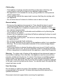
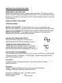
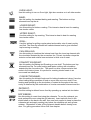
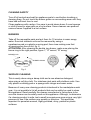
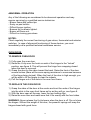
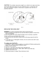
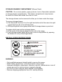
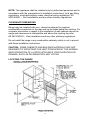
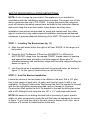
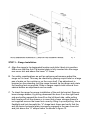
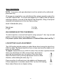
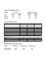
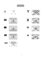
FREE STANDING RANGE
GAS AND ELECTRIC APPLIANCE
MODELS: AXC1200FWT
AXC900FWT
INSTRUCTION GUIDE
INSTALLATION
AND MAINTENANCE
IMPORTANT: SAVE THESE INSTRUCTIONS.
Please retain these instructions with the appliance for future reference
1
SAFETY
Read and follow all instructions before using this appliance to prevent
the potential risk of fire, electrical shock, personal injury or damage to the
appliance as a result of improper usage of the appliance.
Do not store or use flammable vapours and liquids in the vicinity of this
appliance.
What to do if you smell gas:
-
Turn off all burners.
Open all doors and windows.
Do not touch any electrical switches.
Call your gas supplier. Follow the gas supplier’s instructions.
To Prevent Fires:
-
Never leave burners unattended whilst in use.
Never use your appliance for warming or heating the room.
Wear proper apparel. Do not wear loose clothing.
Do not store or use flammable vapours, liquids or items in the vicinity of this
or any other appliance.
- Do not spray aerosols in the vicinity of this appliance while it is in operation.
- Do not use water on grease fires. Smother fire with a fire blanket or use a
dry chemical or foam type extinguisher.
Safety when cooking:
- Do not store flammable materials in oven or near cooktop surface.
- Use only dry potholders. Moist or damp potholders on hot surfaces may
result in burns from steam.
- Do not let potholder touch heating elements.
- Do not use a towel or other bulky cloth.
- Do not use aluminium foil to line surface unit drip bowls or oven bottoms,
except as suggested in the manual. Improper installation of these liners
may result in a risk of electric shock, fire or damage to enamel surfaces.
2
Child safety:
- The handles of cooking utensils should be positioned so that they are
turned inward, and do not extend over adjacent heating areas.
- The appliance is not intended for use by young children or infirm persons
without supervision.
- Young children should be supervised to ensure that they do not play with
the appliance.
- Do not store items of interest to children near or above a range.
General safety:
- During use the appliance becomes hot. Care should be taken to avoid
touching heating elements inside the oven or on the cooktop surface.
- Where this appliance is installed in marine craft or in caravans, it shall not
be used as a space heater.
- Do not obstruct the flow of combustion and ventilation air by blocking the
room vents or air intakes.
- Ensure that the appliance is switched off before replacing the lamp to avoid
the possibility of electric shock.
- Use care when opening door. Let hot air or steam escape before removing
or replacing food.
- Do not heat unopened food containers.
- Do not spray aerosols in the vicinity of this appliance while it is in operation.
- Warning: Do not store flammable materials in the cooker storage drawer
compartment.
- Place oven shelves in desired location while oven is cool. If shelf must be
moved while oven is hot, do not let potholder contact hot heating elements.
- When a rangehood is installed above this appliance, clean filters frequently.
Warning: To reduce risk of tipping of the appliance from abnormal usage or
by excessive loading of the oven door, the appliance must be secured by a
properly installed anti-tip device. To check if the device is installed properly,
remove lower storage drawer or lower foot cover and look beneath the “U”
shape back frame and verify that the anti-tip device plate is properly engaged
in the rear cover slot just above the frame. You should check this anytime the
range has been moved.
User Servicing:
Do not repair or replace any part of the appliance unless specifically
recommended in the manual. All other servicing should be referred to a
qualified technician.
Disconnect electrical supply before servicing the appliance.
3
INSTRUCTION GUIDE FOR GAS COOKTOP
GAS BURNER IGNITION AND REGULATION
For models with single action automatic ignition, place a pan on the burner
grate. Push in and turn the knob counterclockwise to the LIGHT-HIGH
setting. A clicking sound will be heard and the burner will light, fig. 2. (All
surface ignitors will spark when any control knob is turned to the LIGHT-HIGH
position), keep it pushed in till burner lights. After the burner lights, turn the
knob to the desired flame size, fig.1.
For models equipped with both electronic ignition and safety device, follow
the same procedure as for models with automatic ignition described above,
but you have to keep pushing in for at less 5 seconds till thermocouple is hot
enough. Then release the knob and the burner should remain on.
During a power failure, hold a lighted match to the desired burner head. Push
in and turn the knob counterclockwise to the LIGHT-HIGH setting. After the
burner lights, turn the knob to the desired flame size, fig.1.
Caution: When lighting the burner, be sure all of the controls are in the OFF
position. Strike the match first and hold it in position before turning to knob to
LIGHT-HIGH.
Low
Light
High
Fig. 1
Fig. 2
4
COOKWARE
To achieve optimum surface cooking performance, select heavy gauge, flat,
smooth bottom pans that conform to the diameter of the cooking area.
Proper pans will reduce cooking times, use less energy and cook food more
evenly.
Remember to use pans with flat bottoms and handles that are easily grasped
and stay cool. To minimise burns, ignition of flammable materials and spillage
due to unintentional contact with the utensil, do not extend handles over
adjacent surfaces burners. Always turn pan handles toward the side or back
of the appliance, not out into the room where they are easily hit or reached by
small children.
NOTES FOR COOKWARE ON GAS BURNERS
We recommend the following pan size per each type of burner, fig. 3:
BURNER TYPE
Rapid – (Large)
Semi-rapid (Medium)
Simmer (Small))
Double ring (Wok)
COOKING PAN BOTTOM SIZE
from 200 to 250 mm Ø
from 150 to 200 mm Ø
from 75 to 150 mm Ø
from 250 to 280 mm Ø
Fig. 3
Burner operational Notes:
- A properly adjusted burner with clean ports will light within a few seconds.
If using natural gas the flame will be blue with a deeper blue inner cone.
- If sooting is noticed on pan bottom, contact a service technician to adjust.
- If the control knob is turned very quickly from HIGH to LOW, the flame may
go out, particularly if the burner is cold. If this occurs, turn the knob to the
OFF position, wait several seconds and relight the burner.
- The flame should not extend beyond the edge of the pan.
5
INSTRUCTION GUIDE FOR OVEN
REMOVING OVEN SHELVES
Slide shelf towards you until it reaches the front stops. Tilt shelf up at the
front to clear the side shelf supports and lift clear. To put shelf back reverse
the above procedure, ensuring the shelf is placed between the two wire side
shelf supports.
OVEN CONTROL FEATURES
CONTROL MENU:
MODEL AXC1200FWT - The left hand 70cm oven is composed of an
electronic programmer, selector switch and a thermostat and the right hand
45cm oven is composed of a manual timer, selector switch and thermostat.
MODEL AXC900FWT - The single oven is composed of an electronic
programmer, selector switch and thermostat.
ON AND OFF NEON INDICATOR
When the Neon indicator is on the oven is
electrically powered and functioning, see fig. 4.
Fig.4
TEMPERATURE NEON INDICATOR
Temperature neon indicator turns on and off to
indicate the elements are turning on and off to
maintain the desired oven temperature, see fig. 5.
o
C
fig.5
ELECTRONIC PROGRAMMER
The clock has a maximum setting of Time of day 11h 59 Min. or 23h 59 Min.,
Cooking end time 11h 59 Min. or 23h 59 Min., Minute minder 23h 59 Min.,
and Cooking duration 10h.
Functions:
Cooking duration, Cooking end time, Time of day, Minute minder “-“ , “+” ,
Manual selection.
Displays:
4-digit 7-segment display for time of day and switching times.
“Dialogue” display to identify condition of timer:
Duration and Manual mode = Cookpot symbol
Automatic programme
=A
Minute minder
= Bell symbol
6
Setting:
Select a function by pressing the function button and set the required time
with +/- buttons.
+/- Buttons:
Pressing the “+” button increases the time set, pressing “-“ decreases it. The
count-up or count-down speed increases the longer the button is held in the
appropriate position.
Setting Time of Day:
Select Time of day function by keeping the duration and end time buttons
pressed together while setting time of day with +/- buttons. Any programme
which has been set is cancelled and the outputs switched on.
Manual Operation:
Press duration and end time button together. The relay contacts will switch
on. The “A” symbol will be erased, the pot symbol illuminated. Any
programme which has been set is cancelled.
Semi-Automatic Operation with cooking duration:
Select cooking duration function and set required end time with the +/- button.
The “A” and cookpot symbols appear. The relay output becomes active. If
time of day = cooking end time the relay output and the cookpot symbol are
switched off. The audible signal sounds and “A” blinks.
Fully Automatic Operation:
Select cooking duration function and set required duration with the +/- button.
The “A” symbol appears. The relay is switched on and the cookpot symbol
appears. Select cooking end time function and the earliest possible end time
is displayed. Set the required end time with the +/- button. The relay and the
cookpot symbol are switched off. The cookpot symbol appears again when
time of day = the calculated start time.
After the automatic programme has ended, the symbol “A” blinks. The audible
signal is heard and the cookpot symbol and the relay are switched off.
Minute Minder:
Select minute minder button and set required time with +/- button. As the time
set elapses the bell symbol is displayed. After the time set has elapsed, the
audible signal sounds.
7
Audible Signal:
The audible signal (1 Hz interval) sounds at the end of a minute minder cycle
or of a cooking programme for a period of 7 minutes. The signal can be
cancelled by pressing any function button.
Pressing the “-“ button without having previously selected a function the
frequency of the signal changes. A selection from 3 possibilities can be made.
The selected signal is audible as long as the “-“ button is pressed.
Programme Start and Verification:
A programme which has been set is carried out after setting the time
required. The “time-to-turn” can be verified at any time by selecting the
appropriate function.
Setting Error Identification:
The setting is incorrect if time of day is in between the calculated cooking
start and end times. If an error has been made, this will be indicated by the
audible signal and by the symbol “A” flashing. The faulty setting can be
corrected by changing one or both functions.
Cancelling a Programme:
A programme can be cancelled by selecting the manual function. After a
programme which has been set comes to an end, it is automatically
cancelled.
MANUAL TIMER
MANUAL MODE: Turn knob left, counterclockwise, up to Hand symbol.
ATTENTION, if knob is left on manual mode the oven will stay on
continuously.
PROGRAMMED COOKING MODE: Turn knob right, clockwise, and select
desired cooking time. At end of cooking time, oven will be automatically turn
off and a beep signal will be heard. Then, to stop the beeping signal just push
timer knob.
SELECTOR SWITCH
This control allows you to choose the desired Oven function mode. The
following illustration give an overview of what happens in the oven with each
mode setting. It also explains which elements heat up for each specific mode.
The lower and circular elements are concealed under the floor and behind
back wall of the oven respectively. The elements will turn on and off to
maintain the oven temperature.
8
OVEN LIGHT;
Use this setting to turn on Oven light, light also remains on in all other modes.
BAKE;
Use this setting for standard baking and roasting. The bottom and top
elements heat up the air.
LOWER ROAST;
Use this setting for bottom roasting. This intensive heat is best for roasting
less tender meats.
UPPER ROAST;
Use this setting for top roasting. This intensive heat is best for roasting
less tender meats.
GRILL;
Use this setting for grilling regular sized and smaller cuts of meat, poultry
and fish. The inner top element will radiate intense heat to give excellent
top browning or searing.
FAN GRILLING;
Use this setting to combine the intense heat from the inner top element with
the circulation assisted by the convection fan. This air circulation crisps the
exterior surface and retains inner moisture in thick cuts of meat.
CONVECTION ROAST;
Use this setting for Baking and Roasting on one shelf. The bottom and top
elements heat up. For even heating and faster cooking with circulation
assisted by the convection fan. The result is a drier, crisper exterior that
seals in the interior juices. It is perfect for roasting tender meats in an
uncovered low sided pan.
CONVECTION BAKE;
Use this setting for delicate foods and for baking breads and cakes. Use also
when baking large quantities of food on more than one oven shelf. Even
heating and speeding up the circulation of heated air throughout the oven
cavity is obtained by the combination of circular convention element and fan.
DEFROST;
Use this setting to defrost frozen food by speeding up natural air circulation.
ROTISSERIE;
Use this setting to roast food using the rotisserie. To use the rotisserie you
must preheat the oven using the grill element. Insert spit with food in the
slotted shaft on the back oven wall, then use front support to keep in place the
rotisserie spit and apply cooking tray below the rotisserie spit as a grease
retainer. Remember to take off the rotisserie handle before closing oven
door. For grilling procedure follow Grill Use chapter.
9
GRILL USE
Set selector switch to grill mode and turn the thermostat knob to maximum
temperature. Allow a period of time for preheating the oven cavity before
grilling food.
SHELF PLACEMENT FOR SPECIFIC FOODS:
1) Frozen pies, large roast, turkey, angel food cakes, thick well-done meat
cuts; shelf position is 1st or 2nd level from the bottom.
2) Bundt cake, most quick breads, yeast breads, casseroles, meats, thick
meat cuts; shelf position is 2nd rack guide from bottom.
3) Cookies, biscuits, muffins, cakes, non frozen pies, thin meat cuts; shelf
position is 2nd and 3rd rack guide from bottom.
4) For grilling food; shelf position is 4th rack guide from bottom or place food
7.5cm or more from the grill element.
COOKING TEMPERATURE - TIME CHART
The following is a guideline only and may need to be adjusted for individual
tastes.
FOOD TYPE
Bread and biscuits
Toasting bread or loaf in a tin
Rolls and sandwiches
White bread
Biscuits (short mixture –
2nd or 3rd shelf)
Cakes and various pastries
Buns
Genoa cake
Crispy cake
Layer cake
Chocolate cake
Fruit cake
Swiss rolls
Cream puffs
Vol-au-vent
Puff pastry biscuits
Short pastry
Gingerbread
Soufflés
Meringues
TEMP. °C T/MIN
190/200
150/160
175/210
45/60
20/25
25/40
125/140
20/30
175
160
160
190
175
120/140
190/200
180
175
180
180
125
180/190
120/125
40/50
40/45
40/45
25/35
25/35
50/70
12/18
15/20
20
20
20
20/25
20
30/35
10
FOOD TYPE
TEMP. °C
T/MIN
Meat
Braised beef (1/1.5 kg.)
Roast veal (1/1.5 kg.)
Meat loaf (1/1.5 kg.)
Lamb (leg or shoulder)
Kid (leg or shoulder)
Pork (loin or ham)
150/160
150/160
150/160
150/160
150/160
175
80/210
120/150
120/150
60/90
45/60
45/60
Poultry
Chicken or capon
Roast pigeons
Turkey
Goose
Duck
170
150/160
150
160
175
90/120
80/100
90/120
150/180
180/200
Fish
Fish in general
190
15/20
Various
Goulash (1/1.5 kg. stew)
180/190
60/75
CLEANING SAFETY
Turn off all controls and wait for appliance parts to cool before touching or
cleaning them. Do not touch the burner grates or surrounding areas until they
have had sufficient time to cool.
Clean appliance with caution. Use care to avoid steam burns if a wet sponge
or cloth is used to wipe spills on a hot surface. Some cleaners can produce
noxious fumes if applied to a hot surface.
BURNERS
Take off the removable parts and put them for 10 minutes in warm soapy
water. Eventual stubborn soils can be removed by using a
nonabrasive pad or a plastic scouring pad, then rinse making sure that
all openings are free of dirt, fig. 6.
ATTENTION: After cleaning the double ring burner, make sure placing the
burner ring in the right position, figure 7; “A” correct, “B” wrong.
BURNER CUP
BURNER CROWN
Fig. 6
fig.7
SURFACE CLEANING
This is easily done using a damp cloth and a non-abrasive detergent,
wipe using a soft dry cloth. For stainless steel parts with stubborn soils. Use
only plastic scrubbing pad or a sponge with vinegar and warm water.
Because of many new cleaning products introduced in the marketplace each
year, it is not possible to list all products that can be safely be used to clean
this appliance. Read carefully the cleaner manufacture’s instructions to be
sure the cleaner can be safely used on this appliance. Although, to determine
if a cleaning product is safe, test a small inconspicuous area using a very light
pressure to see if the surface may scratch or discolour. This particular
important for porcelain enamel, highly polished, shiny, painted or plastic
surfaces.
11
ABNORMAL OPERATION
Any of the following are considered to be abnormal operation and may
require servicing by a qualified service technician:
- Burner flame with yellow tips.
- Sooty on pan bottom.
- Difficult burner ignition.
- Burners fail to remain lighted.
- Burner will flame out.
- Difficult on turning gas valves.
NOTES:
Check regularly the correct functioning of gas valves, thermostat and selector
switches. In case of abnormal functioning of these devices, you must
immediately call a qualified technical assistance service.
OVEN DOOR
TO REMOVE OVEN DOOR
1) Fully open the oven door.
2) Raise the U-clip over the hook on each of the hinges to the “locked”
position, see figure 8. This will prevent the hinge from snapping closed
when the door is removed.
3) Grasp the door by the sides toward the back. Raise the front of the door
several inches (there will be some spring resistance to overcome because
of the hinge being locked). When the front of the door is high enough, you
will be able to lift the hinges to clear the indents
4) Pull the hinges out of the slots in the oven front frame.
TO REPLACE THE OVEN DOOR
1) Grasp the sides of the door at the centre and inert the ends of the hinges
into the slots in the oven front frame as far as they will go, see figure 8.
2) With the door open all the way, lower the two locking clips.
3) Raise the oven door and make sure that it fits evenly with the front sides.
WARNING: Never release the U-clip levers when the door is off. Do not close
the hinges. Without the weight of the door, the powerful springs will snap the
hinges closed with great force.
12
CAUTION: Do not place excessive weight on or stand on an open oven door.
This could cause the range to tip over, break the door, or injure the user.
Also, do not attempt to open or close door or operate oven until door is
properly replaced.
Fig. 8
REPLACING THE OVEN LIGHT
WARNING; To prevent electrical shock and or personal injury:
1) Before replacing the light bulb, be sure the electric power is turned off at
the circuit breaker.
2) Do not operate the oven unless the light cover is securely in position.
3) Be sure the oven and light bulb are cool.
4) Do not touch hot bulb with a damp cloth as this may cause the bulb to
break.
5) If the light cover is damaged or broken, do not use the oven until a new
cover is in place.
To replace oven light bulb:
1) WARNING - Ensure that the appliance is switched off before replacing the
lamp to avoid the possibility of electric shock.
2) Remove oven shelves.
3) Remove, unscrewing, lens bulb cover and light bulb.
4) Replace bulb with a 25 W – 250V, SES 300oC oven bulb only.
5) Replace lens bulb cover.
6) Reconnect power to range. Reset electronic clock.
13
STORAGE DRAWER COMPARTMENT (Where Fitted)
CAUTION: Do not store plastic, paper products, food or flammable materials
in storage drawer compartments. The drawer compartments may become
too warm for these items when the oven is in use.
The storage drawer can be removed to allow you to clean under the range.
To remove storage drawer:
1) Pull downward the lever A on the right hand side and at the same time pull
upward the lever B on the left hand side
2) While pulling both levers grasp sides and lift storage drawer up and out.
To replace both lower and top storage drawer:
1) Fit the ends of the drawer glides into the rails in the range.
2) Push storage drawer gently all the way, once in stop position try opening
the drawer to verify correct application.
INSTALLATION INSTRUCTIONS
WARNING:
- Only qualified personnel should install or service this range.
- Read “safety instructions” in this book before using range.
- Improper installation, adjustment, alteration, service, maintenance or use of
range can result in serious injury or property damage.
- Do not lift or move range by door handles or backguard.
- Remove shipping polystyrene from ALL cooktop burners.
14
NOTE: This appliance shall be installed only by authorised personnel and in
accordance with the manufacturer’s installation instructions, local gas fitting
regulations, municipal building codes, electrical wiring regulations, AS
5601/AG601 – Gas Installations and any other statutory regulations.
CLEARANCE DIMENSIONS
Range may be installed with zero clearance adjacent to (against)
combustible construction at the rear and on the sides below the cooktop. For
complete information in regard to the installation of wall cabinets above the
range and clearances to combustible wall above the cooking top refer,
AS 5601/AG601 – Gas Installations and any other statutory regulations.
Do not install the range in any combustible cabinetry which is not in accord
with these installation instructions.
CAUTION: SOME CABINETS AND BUILDING MATERIALS ARE NOT
DESIGNED TO WITHSTAND THE HEAT PRODUCED BY THE NORMAL
SAFE OPERATION OF A LISTED APPLIANCE. DISCOLORATION OR
DAMAGE, SUCH AS DELAMINATION, MAY OCCUR.
LOCATING THE RANGE
15
Additional Installation Requirements
Do not set range over holes in the floor or other locations where it may be subject to strong
drafts. Any opening in the wall behind the range and in the floor under the range should be
sealed. Make sure the flow of combustion or ventilation air is not obstructed.
A range should not be installed over kitchen carpeting.
VENTILATION
Ventilation must be in accordance with AS5601/AG 601 – Gas Installations. The appliance
must be install in a well-ventilated environment to guarantee a correct combustion gases
exchange, proper air circulation and working temperature within safety limits.
MODEL NUMBER PLATE
The Model Number Plate is located on the underneath case. A second Model Number
Plate is applied on the front page of the instruction booklet.
Check the model number plate to ensure that the appliance is suitable for the available
gas supply.
16
ANTI-TIP DEVICE INSTALLATION INSTRUCTIONS
NOTE: A risk of range tip over exists if the appliance is not installed in
accordance with the installation instructions provided. The proper use of this
device minimises the risk of TIP-OVER . In using this device the consumer
must still observe the safety precautions as stated in the Instruction Manual
and avoid using the oven door and/or lower drawer as a step stool.
Installation instructions are provided for wood and cement wall. Any other
type of construction may require special installation techniques as deemed
necessary to provide adequate fastening of the ANTI-TIP bracket to the wall.
STEP 1 – Locating The Bracket (see fig. 11)
A. Mark the wall where either the right or left rear “EDGE” of the range is to
be located.
B. Place the Anti-Tip Bracket 370mm for AXC900FWT or 520mm for
AXC1200FWT range from the marked “EDGE” toward centre of opening
and against the back wall with a first hole height of 45mm plus “A”
(distance between side wall bottom edge and floor after range levelling) as
shown in figure 11.
C. Use the bracket as a template and mark the required holes, as shown in
figure 11, for the type of construction you will be using.
STEP 2 – Anti-Tip Bracket Installation
Locate the centre of the two holes to be drilled on the wall. Drill a 1/8” pilot
hole in the centre of each hole. (A nail or awl may be used if a drill is not
available). On Wood Construction Wall secure the Anti-Tip bracket to the wall
with the two self-drilling screws provided, and on Cement or Concrete
Construction Wall secure the Anti-Tip bracket to the wall by drilling two holes
with a 3/8” drilling bit and using the two 3/8” x 1 ½” wall plugs with screw.
NOTE: Be aware of not drilling the wall hole in proximity of pipes, electric
cables or other components inside the wall that may be damaged. As shown
in figure 11 you have two slots in the rear cover to choose from. Also, use a
minimum of 2 screws to install bracket to the wall.
17
Fig. 11
STEP 3 – Range Installation
A. Align the range to its designated location and slide it back into position.
Make sure that the Anti-Tip bracket plate is fully inserted into the range
rear cover slot and above the lower “U” frame.
B. For safety considerations as well as optimum performance adjust the
range so it is level. This may be checked by placing a spirit level or a large
pan of water on the cooktop or on the oven shelf. If an adjustment is
required on free standing, pull the range forward, tip the range and rotate
the levelling feet as required. Slide-in ranges require total removal from
cabinet before an adjustment can be made.
C. To check the range for proper installation of the anti-tip bracket: Remove
lower storage drawer, by pulling downward the lever A on the right hand
side and pulling upward the lever B on the left hand side, while pulling
both levers pull out the drawer or in case that a lower storage drawer is
not supplied remove the lower foot cover by lifting it up and pulling. Use a
flashlight and look beneath the “U” shape back frame and verify that the
anti-tip device horizontal plate is properly engaged in the rear cover slot
and just above the “U” shape frame. As shown in figure 12.
18
Fig. 12
D. Proceed with the remainder of the installation instructions.
CONNECTING THE RANGE
ELECTRICAL SUPPLY
IMPORTANT: The electrical supply to this appliance must
only be installed by a suitably qualified electrician.
The electrical connection to this appliance must be
connected in accordance with AS/NZS 3000 Wiring Rules
and any other relevant regulations.
The fixed wiring supplying this equipment shall have a
switch installed that has an air gap contact separation
in all active (phase) conductors. (this is required for
fixed wired units only)
An isolation switch must be provided near the appliance
in an accessible position, in accordance with
AS/NZS 3000 clause 4.3.11
19
ELECTRICAL INSTALLATION
The Range requires a single-phase 240 VAC - 50 Hz electrical supply,
please refer to the appliance data label for rating information.
House wiring and fusing must comply with AS/NZS 3000 Wiring Rules and
any other relevant regulations.
Important: This appliance must be properly earthed.
Electrical damage can occur if this appliance is incorrectly installed – any
such damage is not covered by the warranty.
GAS SUPPLY
In Australia, this appliance shall be installed only by authorised personnel and
in accordance with the manufacturer’s installation instructions, local gas fitting
regulations, municipal building codes, electrical wiring regulations, AS
5601/AG 601 - Gas Installations and any other statutory regulations.
A ½” BSP inlet connection with annealed copper pipe is recommended.
Be sure all control knobs are set in the OFF position prior to supplying gas to
the hob.
Test for gas leaks by approved method. NEVER CHECK FOR GAS LEAKS
WITH A FLAME.
BEFORE LEAVING
Check all connections for gas leaks with soap and water. DO NOT use a
naked flame for detecting leaks. Ignite all burners to ensure correct operation
of gas valves, burners and ignition. Turn gas taps to low flame position and
observe stability of the flame. When satisfied with the cooker, please instruct
the user on the correct method of operation. In case the appliance fails to
operate correctly after all checks have been carried out, please refer to
section below for contact details.”
20
GAS CONVERSION
NOTE: Conversion and gas adjustment must be carried out by authorised
personnel only.
All ranges are supplied for use with Natural Gas unless specially ordered for
use with Propane Gas. To convert the appliance to Propane Gas will require
switching injectors, removal of the Natural Gas Regulator, fitting of test point
assembly and adjustment of the low flame setting.
INLET PRESSURE (kPa)
Natural gas
LP gas
1.0 kPa
2.75 kPa
GAS BURNER INJECTOR CONVERSION
To switch injectors, unscrew fixed injector using a proper 7 Hex. key tool and
replace it with new injector for new gas setting.
For proper injector size, follow Burner’s Technical Data chart and fig. 7.
LOW SETTING VALVE ADJUSTMENT
The LOW setting should produce a stable flame when turning the knob from
HIGH to LOW. The flame should be 5mm or lower and must be stable on all
ports on LOW setting.
To adjust: Operate burner on HIGH for about five minutes to preheat burner
itself. Turn knob back to LOW; remove knob, and insert a
small flat tip screwdriver into the centre of the valve stem.
Adjust the flame size by turning adjustment screw in either
direction, while holding the stem (fig. 17)
Flame must be of sufficient size to be stable on all burner ports.
If flame adjustment is needed, adjust ONLY on the LOW setting.
Never adjust flame size on higher setting.
21
Fig. 17
COOKTOP TECHNICAL DATA
Burner
Wok
Large
Medium
Simmer
MJh/hr
Natural
Propane
12.0
10.7
11.8
9.5
6.8
5.5
4.1
3.2
Injector Size, mm
Natural
Propane
1.60
0.90
1.55
0.85
1.18
0.65
0.90
0.50
OVEN TECHNICAL DATA
ELECTRICAL DATA
VOLTAGE
TOTAL APPLIANCE LOAD
TOP HEATING ELEMENT
BOTTOM HEATING ELEMENT
CIRCULAR HEATING ELEMENT
GRILL HEATING ELEMENT
OVEN LIGHT
OVEN FAN
COOLING FAN
ROATISSERI MOTOR
AXC12 00FWT
45cm
70cm
CONVECTION
MULTIFUNCTION
OVEN (ST)
OVEN (MT)
230 – 240 Vac~ 50Hz
4.5 kW
0.75 kW
0.8 kW
1.4 kW
1.5 kW
2.2 kW
1.5 kW
1.8 kW
25 W
25 W
25 W
25 W
25 W
4W
-
COOKING CAVITY
HEIGHT
WIDTH
DEPTH
WORKING VOLUME
330mm
300mm
310mm
31 lt.
AXC900FWT
90cm
MULTIFUNCTION
330mm
550mm
310mm
56 lt.
DIMENSIONS OF THE APPLIANCE
Series
AXC1200FWT
AXC900FWT
Width (mm)
Height (mm)
Depth (mm)
1200
900
900
900
700
700
22
2.8kW
1.05 kW
1.5 kW
2.5kW
1.8 kW
2 x 25 W
25 W
25 W
300mm
570mm
400mm
68 lt.
OVEN MODES
23
SERVICE – PARTS INFORMATION
For Service Call – 1300 650 020
For Spare Parts Call – 03 9569 7744
Andi Appliances Pty Ltd
1 Stamford Road
Oakleigh VIC 3166
Ph: 03 9569 1255
Fax: 03 9569 1450
Please give the complete model and serial number of the range which is
located on the range model number plate.
17122002AUS
24