1
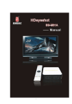
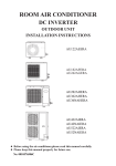
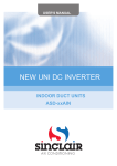
AV100 B/C AM/FM RADIO WITH iPod DOCKING FEATURE Owner’s Manual Congratulations Thank you for purchasing the Acoustic Research AV100 AM/FM Radio Receiver System with iPod compatibility. The B or C suffix after the model number indicates a black (B) or cherrywood (C) cabinet. Besides featuring standard AM and FM radio reception with dedicated antenna input connections, the AV100 also provides an iPod docking connector for listening to downloaded material from the internet when the iPod mode is selected. Additional features include AUX 1 and AUX 2 inputs for connection of external devices such as CD and MP3 players and an audio output jack for connection to an external subwoofer speaker. AM and FM tuning is achieved using the precision vernier tuning knob on the front of the unit, while volume level is adjusted with a continuous 360° rotary volume control. IMPORTANT-----Read These Instructions 1. 2. 3. 4. 5. 6. 7. 8. 9. 10. 11. 12. 13. 14. 15. 16. 2 Keep these instructions. Heed all warnings. Follow all instructions. Do not use this apparatus near water. Clean only with dry cloth. Do not block any ventilation openings. Install in accordance with the manufacture's instructions. Do not install near any heat source such as radiators, heat registers, stoves, or other apparatus (including amplifiers) that produce heat. Do not defeat the safety purpose of the polarized or grounding-type plug. A polarized plug has two blades with one wider than the other. A grounding type plug has two blades and a third grounding prong. The wide blade or the third prong are provided for your safety. If the provided plug does not fit into you outlet. Consult an electrician for replacement of the obsolete outlet. Protect the power cord from being walked on or pinched particularly at plugs, convenience receptacles, and the point where they exit from the apparatus. Only use attachments/accessories specified by the manufacturer. Use only with the cart, stand, tripod, bracket, or table specified by the manufacturer, or sold with the apparatus. When a cart is used, use caution when moving the cart/apparatus combination to avoid injury from tip-over. Unplug this apparatus during lightning storms or when unused for long periods of time. Refer all servicing to qualified service personal. Servicing is required when the apparatus has been dam aged in any way, such sa power-supply cord or plug is damaged, lipuid has been spilled or objects have fallen into the apparatus, the apparatus has been exposed to rain or moisture, does not operate normally, or has been dropped. The apparatus shall not be exposed to dripping or splashing and no objects filled with liquids, such as vases, shall be placed on the apparatus. The appliance coupler used as disconnect device shall remain readily operable. To reduce the risk of fire or electric shock, do not expose this apparatus to rain or moisture. AV100 FCC Information Note: This equipment has been tested and found to comply with the limits for a Class B digital device, pursuant to Part 15 of the FCC Rules. These limits are designed to provide reasonable protection against harmful interference in a residential installation. This equipment generates, uses and can radiate radio frequency energy and, if not installed and used in accordance with the instructions, may cause harmful interference to radio communications. However, there is no guarantee that interference will not occur in a particular installation. If this equipment does cause harmful interference to radio or television reception, which can be determined by turning the equipment off or on, the user is encouraged to try to correct the interference by one or more of the following measures: — Reorient or relocate the receiving antenna. — Increase the separation between the equipment and receiver. — Connect the equipment into an outlet on a circuit different from that to which the receiver is connected. — Consult the dealer or an experienced Radio/TV technician for help. This device complies with Part 15 of the FCC Rules. Operation is subject to the following two conditions: (1) This device may not cause harmful interference, and (2) this device must accept any interference received, including interference that may cause undesired operation. The user is cautioned that changes or modifications not expressly approved by XM® Satellite Radio, Inc. can void the user’s authority to operate this device. By adhering to these warnings and safety considerations, accidents and/or personal injury can be avoided. Safety Precautions z Do not expose the device and the remote control to water or moisture. z Only operate the device in the specified temperature range of 0°C to 40°C. z Make sure there is sufficient ventilation for the device. There must be a minimum gap of 10 cm between objects to the side, to the rear and above the device. z In the event of contact with moisture or liquids remove the mains adapter immediately. z Only clean the device using a dry cloth. Do not use any cleaning agents or chemical solvents when cleaning, as these could damage the surface of the device. z Never open the device. z The device should not continue to be operated if there is visible damage to the mains cable. A damaged cable should not be repaired, but must be replaced. z Always refer to a qualified specialist for any maintenance or repair work. AV100 3 AV100 System Components AV100 AM/FM Radio with iPod Docking Feature (iPod Not Included) Remote Control with Battery AM Antenna FM Antenna AC Line Power Cord 4 AV100 Installing and Setting Up the AV100 You can begin to enjoy your AV100 Radio system as soon as the installation is completed as follows: 1. Determine the desired area where the unit is to be installed; i.e., table top, stereo cabinet, etc. Note: If possible, the unit should be positioned near a window to achieve the best reception with the AM and FM antennae. 2. Make sure the line power rocker switch at the rear of the unit is in the off (O) position. Then plug the power cable into the mating connector located to the right of the switch. Plug the other end of the cable into a wall outlet supplying 120 volts, 60Hz. Note: If the line switch is in the on (I) position when the power cord is plugged into the outlet, the mode LED indicators on top of the unit will all flash on for 2 seconds and then go out. If the switch is then turned off, the indicators will momentarily flash on and go out. 3. Connect the FM antenna lead to the FM ANTENNA (F) connector at the rear of the unit. 4. Construct the AM antenna stand: a. Hold the antenna loop upside down. b. Fold the stand piece up and over, mating the slot on this piece with the three tabs on the bottom of the antenna. Press until the two pieces snap together, making sure the antenna lead wire exits cleanly through the side of the stand. 5. Connect the AM antenna lead wires into the 300-Ohm AM ANTENNA terminals at the rear of the unit. 6. Press the line power rocker switch on the rear of the unit to the on ( I ) position; the mode LEDs flash on for 2 seconds and then go out. 7. Momentarily press the POWER ( ) button on top of the unit; the audio power output vacuum tubes visible through each window at the front of the unit light up, indicating the unit is powered on. In addition, the mode LED on the top will light indicating the mode in affect prior to power turnoff. AV100 Control Features The AV100 provides 3 control buttons, plus a volume control wheel and a tuning knob (See Figure x.) Power On/Off: 1. Press the Line Power rocker switch at the rear of the unit to the on ( I ) position; the mode LEDs flash for 2 seconds and go out. 2. With the line power switch on, power is applied to the radio system when the Power ( ) button on top of the AV100 or on the Remote Control is momentarily pressed; the mode LED indicating the last system mode in effect prior to turnoff lights blue, and the Radio system is ready for use. 3. Power is turned off when the Power button is momentarily pressed; the mode LEDs flash once and the unit powers down as evidenced by the audio output tubes turning off . AV100 5 MODE Button Each time the MODE button is pressed, the operating status of the unit changes in sequence from AM through AUX 2; as the mode changes, the associated blue LED lights accordingly. When the AV100 is turned off, the last operating mode in effect at the time is re-established when the unit is again turned on. VOLUME Control The VOLUME control provides a continuously adjustable ( 360° ) audio level; when rotated clockwise (CW), the volume level increases, and counterclockwise (CCW) rotation decreases the volume level. Tuning Knob The tuning knob has top and bottom dial graduations indicating FM and AM frequency settings, respectively. The amber TUNE LED indicator to the right of the control lights as each station is selected on the associated dial; the brightness of the indicator varies in proportion to both the strength of the station signal and the station tuning accuracy. The indicator is the brightest when the station signal strength is maximum and when optimum station tuning is achieved. When the FM station is broadcasting in stereo, the green STEREO LED indicator to the left of the control comes on provided signal strength is adequate. Remote Control Features The remote control provides control of AV100 operation using an infrared (IR) transmitter whose signal is picked up by the IR receiver at the front of the unit. 1. MONO/STEREO Button: When pressed, alternately selects stereo or mono mode operation for AV100; the STEREO LED indicator lights green on the front of the unit. 1 2. POWER Button: This button turns AV100 power on and off. 3. MUTE Button: When pressed, this button mutes the audio output from the AV100. 4. Play/Pause Button ( ) : When pressed in iPod mode, alternately plays or pauses playback of audio/video data. 5. MENU Button: When pressed in iPod mode, jumps to next higher selection menu. 10 3 9 4 8 5 6. Up/Down ( / ) Buttons: When pressed, these buttons provide up/down navigation through the current iPod menu. 7. Skip to Previous/Next Track ( / ): When pressed in iPod mode, initiates skip to the previous or next audio/video track. 2 6 7 8. ENTER Button: When pressed in iPod mode, provides selection of highlighted item in the current menu. 9. VOL +/- Buttons: When pressed, these buttons increase or decrease the audio output level from the AV100. 10. MODE Button: When pressed, provides sequential selection of AV100 mode of operation from AM through AUX 2. 6 AV100 Functions of Controls, Indicators and Connectors AV100 Radio System, Rear View 1 2 7 6 3 4 5 AV100 Radio System, Top View 18 8 9 17 10 16 11 15 14 13 12 AV100 Radio System, Front View 25 19 20 21 24 AV100 23 22 7 Functions of Controls, Indicators and Connectors (Cont) 1. POWER ON/OFF Rocker Switch: When pressed to the ON ( I ) position, AC input power is applied to the radio system, placing it in the standby mode. 2. AC IN Power Connector: 2-prong male power connector for power cable connection to 120V, 60Hz power. 3. SUB OUT Audio Connector: Female RCA audio output connector to external subwoofer speaker. 4. L / R AUX 2 INPUT Connectors: Female RCA audio input connectors for connection to external audio equipment such as a CD player or other audio output source. 5. S-VIDEO Connector: Provides video output signal from a video iPod* to an external TV or monitor. 6. AM ANTENNA / 300 OHM Terminals: Provide connection for the AM loop antenna for AM signal reception. 7. FM ANTENNA / 75 OHM Connector: Provides connection for the FM antenna F connector for FM signal reception. 8. Protective Cover: Covers the iPod connector bay when iPod is not in use. 9. VOLUME Control: Continuous rotary control wheel for increasing and decreasing the volume of the audio output level; clockwise (CW) rotation increases volume, counterclockwise (CCW) rotation decreases volume. 10. POWER ( ) Pushbutton : Momentarily pressing this button applies power to the radio system, switching from the standby to on mode and vice-versa. 11. AUX 2 Indicator: This LED indicator lights blue when the AUX 2 mode is selected using the MODE switch. 12. AUX 1 Indicator: This LED indicator lights blue when the AUX 1 mode is selected using the MODE switch. 13. iPod Indicator: This LED indicator lights blue when the iPod mode is selected using the MODE switch. 14. FM Indicator: This LED indicator lights blue when the FM mode is selected using the MODE switch. 15. Ventilation Port: Provides cooling air for the audio power output vacuum tubes. 16. AM Indicator: This LED indicator lights blue when the AM mode is selected using the MODE switch. 17. MODE Pushbutton: Each time this button is pressed, the radio system operating mode switches in sequence from AM through AUX 2 and back again. 18. iPod Connector Bay: Provides male multi-pin connection to an installed iPod; connection compatibility is achieved with the supplied iPod adapter or with the adapter included with the iPod. 19. TUNE Indicator: Intensity of this amber LED is proportional to station tuning accuracy; the brighter the LED, the more optimum the reception. 20. Tuning Dial: This vernier control provides selective tuning of the AM and FM stations; the upper dial indicates the FM frequency range from 87.5MHz to 108MHz, while the bottom dial indicates the AM frequency range from 530kHz to 1710kHz. 21. Audio Power Tube Windows: These windows provide a means of observing the left and right channel power output vacuum tubes. 22. Audio Headphone ( ) Jack: Provides a 3.5mm connection for audio headphones. 23. Infrared (IR) Window: IR receiver for commands from the remote control. 24. AUX 1 Input Jack: Provides a 3.5mm stereo input connection for an MP3 player or similar device. 25. STEREO Indicator: This green LED illuminates when the FM station is broadcasting in stereo mode. *Refer to iPod compatibility list on page 9. 8 AV100 AV100 Operation Preoperational Considerations Prior to operation, perform the following steps: 1. Remove the protective film from the battery compartment of the remote control. 2. Connect the power and antenna cables to the AV100 as outlined previously. 3. Apply line power to the AV100 by pressing the line power rocker switch on the rear of the unit to the on (I) position; the mode LEDs flash on for 2 seconds and then go out. The AV100 is now in the standby mode. 4. Press the POWER button on the top of the unit or on the remote control to turn the unit on; the last operating mode in effect prior to shutdown is indicated by the blue LED on top of the unit, unless the AV100 is being turned on for the first time. Note: Despite a low degree of energy consumption in the standby mode, it is recommended that the line switch be set to the off (O) position if the AV100 is not going to be used for a prolonged period. 5. Select an input source using the MODE button. Note: If an external subwoofer is to be incorporated into the AV100 system, connect the subwoofer to the SUB OUT plug at the rear of the unit using an RCA cable with a male RCA jack. Using the Radio 1. FM Operation: With the supplied FM antenna connected to the FM ANTENNA jack at the rear of the unit, press the MODE switch so the blue FM indicator is lit. Set the FM radio to the desired station using the upper tuning knob dial, and adjust the volume to the desired listening level. If headphones are to be used, ) at the front of the unit. connect them to the headphones jack ( 2. AM Operation: With the supplied AM antenna connected to the AM ANTENNA jack at the rear of the unit, press the MODE switch so the blue AM indicator is lit. Set the AM radio to the desired station using the bottom tuning knob dial, and adjust the volume to the desired listening level. If headphones are to be used, connect them to the headphones jack ( ) at the front of the unit. Using the AUX Inputs 1. AUX 1 Input: If an external audio source is to be used, such as MP3 player, etc., connect the device to the AUX 1 input at the front of the unit using a 3.5mm male stereo plug. 2. AUX 2 Input: If an external audio source such as a CD player or other compatible device is to be used, connect the device to the AUX 2 L and R plugs using an RCA cable with male RCA jacks. Using the iPod Dock 1. Remove the protective cover from the iPod system connector bay. 2. Choose the compatible adapter/holder for your iPod model and install it in the bay. Note: The AV100 comes equipped with an iPod adapter installed in place in the iPod bay, plus an additional adapter if needed. Most iPods come with their own (original) adapters which can also be used if necessary. 3. Install the iPod carefully onto the iPod connector and press down lightly until the iPod bottoms into the recess. The iPod will be inclined slightly to the rear of the AV100. AV100 iPod CONNECTOR BAY ADAPTER / HOLDER iPod CONNECTOR 9 Charging the iPod: The iPod’s battery is charged when the AV100 is switched on (independent of the input source selected). This charging function is not supported in the standby mode. Special AV100 iPod Features The AV100 iPod feature is compatible with the following models: iPod Video Nano-Classic 3rd generation 1GB 2GB 4GB NOT COMPATIBLE iPod-Classic 5th generation (color display) 20GB 30GB NOT COMPATIBLE The following iPod models are compatible via the AUX 1 input and an additional 3.5 stereo jack: ------- and other MP3 players Remote Control Battery Replacement / Disposal If the remote control stops working properly, the battery may need to be changed as shown below. Use a lithium button cell (CR2025) and pay attention to the correct polarity. Battery Replacement 1. Remove the battery holder. 2. Insert the battery into the battery holder and insert the battery holder into the remote. Be sure to observe the correct polarity. 3. Align the battery holder with the remote control and push in until the holder clicks. Ö CR2025 Battery Disposal Old batteries are hazardous waste and must be disposed of in accordance with current regulations. 10 AV100 Specifications Frequency Range: AM (UL) FM (UL) 530kHz - 1710kHz 87.5MHz - 108MHz Power Amplifier: 2” x 3” magnetic shielded speaker, 10 W RMS @ 10% THD, Frequency Response: 80Hz - 20kHz 120 VAC 60Hz power supply 300 Ohm twin lead to connect the AM antenna 75 Ohm F-connector to connect the FM antenna RCA-type jack AUX 1 for external audio input source 3.5mm stereo AUX 2 INPUT jack for external audio source input Input/Output: Input Output Dimensions (W x H x D) AV100 Analog output for connection to an external subwoofer S-Video jack for CVBS output 350mm x 120mm x 290mm (13.78” x 4.7” x 11.4”) 11 © 2007 Audiovox Electronics Corporation, 150 Marcus Blvd., Hauppauge, NY 11788 128-8246 12 AV100