1
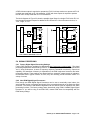
JFL SERIES LOUDSPEAKER
OWNER’S MANUAL
EAW Part: RD0465(A)
Page 2 of 18 RD0465(A) JFL SERIES OWNER’S MANUAL
Table Of Contents
1. READ THIS FIRST................................................................................................................................5
1.1 SAFETY PRECAUTIONS .........................................................................................................................5
1.2 GENERAL PRECAUTIONS ......................................................................................................................5
2. INTRODUCTION...................................................................................................................................6
3. UNPACKING.........................................................................................................................................6
3.1 CONTENTS ..........................................................................................................................................6
4. JFL210 ARRAY DESIGN .....................................................................................................................7
4.1 JFLWIZARD SOFTWARE .......................................................................................................................7
4.1.1
Computer Requirements ............................................................................................................7
4.1.2
JFLWizard Results .....................................................................................................................7
4.2 GROUND STACKING .............................................................................................................................7
4.3 SUBWOOFERS IN THE ARRAY ...............................................................................................................7
4.3.1
General Considerations..............................................................................................................7
4.3.2
JFL118 Subwoofers ...................................................................................................................8
4.3.3
Suspending JFL118 Subwoofers ...............................................................................................8
4.3.4
Signal Delay on Subwoofers ......................................................................................................8
5. ARRAY OPERATION ...........................................................................................................................8
5.1 OVERVIEW ...........................................................................................................................................8
5.2 ENGINEERING DESIGN ..........................................................................................................................8
5.3 SYSTEM BLOCK DIAGRAM.....................................................................................................................8
5.4 SIGNAL PROCESSING ...........................................................................................................................9
5.4.1
Factory Digital Signal Processing Settings ................................................................................9
5.4.2
Non-EAW Digital Signal Processors ..........................................................................................9
5.5 USER ADJUSTMENTS ..........................................................................................................................10
5.5.1
JFL210 HF Shading – Single-Amp Mode.................................................................................10
5.5.2
JFL210 HF Shading – Bi-Amp Mode .......................................................................................10
5.6 AMPLIFIER POWER REQUIRMENTS ......................................................................................................10
5.6.1
Power Ratings ..........................................................................................................................10
5.7 INPUT CONNECTIONS .........................................................................................................................11
5.7.1
JFL210 Input Connections .......................................................................................................11
5.7.1.1
5.7.1.2
5.7.2
Single-amp Mode ................................................................................................................................11
Bi-amp Mode .......................................................................................................................................12
JFL118 Connections ................................................................................................................12
6. RIGGING & HANDLING .....................................................................................................................12
6.1 RIGGING OVERVIEW ...........................................................................................................................13
6.2 RIGGING WARNINGS ..........................................................................................................................13
6.3 PERMANENT INSTALLATION SUSPENSION.............................................................................................13
6.3.1
PI Array Working Load Limit (WLL)..........................................................................................13
6.3.2
A Note On Eyebolts..................................................................................................................14
6.3.3
Permanent Installation Overview..............................................................................................14
6.3.4
JFL210 Arrays ..........................................................................................................................14
6.3.5
JFL118 Arrays ..........................................................................................................................15
6.3.6
Mixed JFL210 & JFL118 Arrays ...............................................................................................15
6.3.7
Setting Array Tilt Angle.............................................................................................................15
6.4 TRIPOD AND POLE MOUNTING ............................................................................................................16
6.4.1
Tripod Mounting........................................................................................................................16
6.4.2
Pole Mounting...........................................................................................................................16
RD0465 (A) JFL SERIES OWNER’S MANUAL Page 3 of 18
7. SERVICE AND MAINTENANCE........................................................................................................17
7.1 GENERAL SERVICE ............................................................................................................................ 17
7.2 PARTS REPLACEMENT KITS................................................................................................................ 17
Page 4 of 18 RD0465(A) JFL SERIES OWNER’S MANUAL
1. READ THIS FIRST
Congratulations on the purchase of your new EAW loudspeaker. You now own one of
the finest professional audio products available - the result of exceptional engineering
and meticulous craftsmanship.
This manual is intended for use with JFL210 and JFL118 loudspeakers. As such, it
contains information that is specific to these loudspeakers. This includes: array design,
user adjustments, amplifier power ratings, input connections, rigging design, and service
and maintenance information. An optional FB121 Fly Bar may be used to suspend
JFL210 and JFL118 loudspeakers and ground stack JFL210 loudspeakers. The
accompanying FB121 Rigging & Ground Stack Instructions should be consulted for
information specific to its use. Finally, information common to all types of EAW
loudspeakers may be found in the accompanying EAW Loudspeaker Owner’s Manual.
This includes: general safety precautions, unpacking/return instructions, rigging
definitions, amplifier selection best practices, signal processing , inspection and
maintenance practices, as well other information common to all loudspeakers.
All three manuals thus apply to the JFL210 and JFL118 loudspeakers. Please read
each and follow all relevant precautions and instructions. This should allow you to obtain
the maximum performance from your new loudspeaker. Where there are conflicts or
overlaps, the information in this manual supersedes the information in any
accompanying manual.
1.1 SAFETY PRECAUTIONS
The terms “Caution,” “Warning,” and “Danger” are used throughout this manual to alert the reader
to important safety considerations. If you have any questions about any aspects of these
precautions, contact your local dealer, distributor, or EAW. The following are the descriptions of
the safety precautions.
CAUTION: describes an operating condition or user action that may expose the equipment or
user to potential damage or danger.
WARNING: describes an operating condition or user action that will cause damage to the
equipment or injure the user.
DANGER: describes an operating condition or user action that will immediately damage the
equipment or be extremely dangerous or possibly life-threatening to the user.
1.2 GENERAL PRECAUTIONS
WARNING: Some aspects of rigging and other related fields for which EAW manufactures, sells,
or distributes equipment are potentially hazardous. Any people using this equipment are
personally responsible for their own safety. EAW transactions are made with the assumption that
the purchaser is a qualified individual or will have only qualified individuals perform work with the
equipment. EAW will not be liable for any damages arising from the use of equipment sold to
purchaser.
WARNING: Only persons with the knowledge of proper hardware and safe rigging techniques
should attempt to suspend JFL210 and JFL118 loudspeaker systems overhead. Failure to follow
this precaution may result in damage to the equipment, injury, or death.
RD0465 (A) JFL SERIES OWNER’S MANUAL Page 5 of 18
2. INTRODUCTION
The JFL Series is a compact format, constant curvature line array system for venues with listener
distances up to about 45 m / 148 ft. It is designed to be incredibly simple to deploy, yet provide
the highest output possible from a compact line array format. The Series includes the 2-way
JFL210 full-range loudspeaker and the complementary single 18 inch JFL118 subwoofer.
This manual provides information about the design, configuration, and operation of JFL210 and
JFL118 Line Arrays. It is intended to be used in conjunction with the Windows®-based JFLWizard
software. Please thoroughly familiarize yourself with this manual.
The JFL210 and JFL118 are physically configured for both temporary installation and permanent
installation. Rigging information for these purposes may be found in this manual and the
accompanying FB121 Rigging & Ground Stack Instructions.
3. UNPACKING
3.1 CONTENTS
JFL210
(1)
JFL210 Loudspeaker
(2)
QRP-JFL Quick Release Pins
(1)
JFL210 & JFL118 Loudspeaker Owner’s Manual
(1)
FB121 Rigging & Ground Stack Instructions
(1)
EAW Loudspeaker Owner’s Manual
JFL118
(1)
JFL118 Subwoofer
(3)
QRP-JFL Quick Release Pins
(1)
JFL210 & JFL118 Loudspeaker Owner’s Manual
(1)
FB121 Rigging & Ground Stack Instructions
(1)
EAW Loudspeaker Owner’s Manual
Page 6 of 18 RD0465(A) JFL SERIES OWNER’S MANUAL
4. JFL210 ARRAY DESIGN
4.1 JFLWIZARD SOFTWARE
Use the JFLWizard software for designing JFL210 arrays. It may be found in the
Downloads/Software section of the EAW website: http://www.eaw.com/downloads/. The
JFLWizard’s primary function is to determine the configuration that will provide the best vertical
performance for a given application. Venue dimensions, the number of enclosures, array aiming
angle, and Fly Bar pick point can be entered manually. Given this information, the Wizard
calculates resultant array performance. For complete instructions about operating the JFLWizard,
click on the About/Help menu when running the software.
4.1.1 Computer Requirements
The JFLWizard requires an IBM-compatible PC with the Windows® 98, Windows® 98SE,
Windows NT®, Windows® 2000, Windows® ME, or Windows® XP operating systems. The
JFLWizard should run in Windows® Vista, but full support is unknown at press time. Windows®
3.x, Windows® 95, and Macintosh® operating systems are not supported..
4.1.2 JFLWizard Results
•
•
•
•
•
•
•
Graphical representations of the array and the venue
On-axis aiming angle for each enclosure as a difference from 0° horizontal
Various angles and throw distances calculated from the venue’s dimensions
Difference between the array beamwidth angle and the needed coverage angles
Height of the array and trim height to the bottom of the array from the floor
Pick Point on the Fly Bar to achieve the calculated array angle when suspended
Weight of the array
4.2 GROUND STACKING
Normally, a ground-stacked JFL Series main array is used where suspension is not possible, too
difficult, or too time-consuming. JFL210 – with or without JFL118 – are also quite effective when
used in stage side fill or audience front fill applications.
Both JFL210s and JFL118s may be ground-stacked alone or in combination. In combination,
always stack JFL210s on top of JFL118s. The recommended minimum and maximum array
quantities are:
Array
JFL210 alone*
JFL118 alone
JFL210 / JFL118
Min
1
1
1/1
Max
4
4
4/2
* Two or more JFL210 must be stacked on accessory FB121 Fly Bar.
WARNING: Ground-stacked arrays, especially the maximum recommended arrays, may present a
tipping hazard and require assembly by personnel qualified to ensure adequate stability. See the
FB121 Rigging & Ground Stack Instructions for correct array assembly. Mechanical assistance may
be required to lift and position enclosures for arrays taller than approximately 5 feet.
4.3 SUBWOOFERS IN THE ARRAY
4.3.1 General Considerations
Although the low frequency performance of JFL Series arrays allows them to be used without
subwoofers for some events, subwoofers will normally be used for live musical performances.
The recommended subwoofer is EAW’s JFL118, specifically designed to complement JFL210 line
arrays.
RD0465 (A) JFL SERIES OWNER’S MANUAL Page 7 of 18
NOTE: Bass performance is often highly program- or venue-dependent, as well as subjective as
to quantity and quality. For this reason the type, quantity, and disposition of subwoofers may vary
considerably with the application. The quantity recommendations below are for general purposes,
providing a balanced system for most music applications. Quantities may need to be adjusted up
or down for specific situations.
4.3.2 JFL118 Subwoofers
JFL118 subwoofers are designed to complement the JFL210 loudspeakers to both extend the low
frequency response and provide more output for the upper low frequencies. JFL118 subwoofers
may either be ground stacked, flown as part of a JFL210 array, or flown separately alongside a
JFL210 array.
A general recommendation is to use JFL210s and JFL118s in a 2:1 ratio.
4.3.3 Suspending JFL118 Subwoofers
The JFL118 enclosure rigging is designed to directly couple to an FB121 Fly Bar and JFL210
enclosures. As such, the JFL118 can be rigged seamlessly with JFL210s. See the FB121 Rigging
& Ground Stack Instructions for more detailed information on rigging a JFL118.
The JFL118s should be the uppermost enclosures when flown as part of a JFL210 array. In this
application, the JFL118s are suspended flat-fronted, with the JFL210s suspended below in a
constant curvature array. When flown separately, JFL118s should be flown so that the spacing
between the line of JFL118 enclosures and JFL210 enclosures is less than 1 m / 3.3 ft.
4.3.4 Signal Delay on Subwoofers
If JFL118s are flown or stacked with JFL210s as configured in the Line Array Wizard, use the
factory signal delay settings.
For other configurations or subwoofers, it will usually be necessary to determine the signal delay
settings by measurement.
5. ARRAY OPERATION
5.1 OVERVIEW
The operation of a JFL Series system involves:
1. Understanding the principles on which it operates.
2. Knowing how to electronically configure it for a specific task.
5.2 ENGINEERING DESIGN
The JFLWizard software uses the fixed splay angle of the enclosure and the desired coverage
pattern to determine the quantity of enclosures in the array that will optimize coverage for the
audience distances and angles within the venue. The basic principle to remember is that more
enclosures provide greater vertical coverage and fewer enclosures provide less vertical coverage.
5.3 SYSTEM BLOCK DIAGRAM
The JFL118 powering mode is single-amp only. The JFL210 has two powering modes: singleamp and bi-amp. A JFL210 operated in single-amp mode only requires a high pass filter for low
frequency excursion protection. This may be implemented in a DSP (Digital Signal Processor),
equalizer, or amplifier with integrated high pass filter. The recommended filter is 60 Hz, 12 to 24
dB Butterworth.
Page 8 of 18 RD0465(A) JFL SERIES OWNER’S MANUAL
A DSP with two outputs is required to operate the JFL210 in bi-amp mode or to operate a JFL210
in single-amp mode with a JFL118 subwoofer. A DSP with three outputs is required to operate
the JFL210 in bi-amp mode with a JFL118 subwoofer.
FULL
Internal Passive
LF/HF Crossover
The block diagrams in Figure 5.3 show the possible signal flows for a single JFL210 with JFL118.
Use the same processor outputs for additional JFL210s and JFL118s on the same mix bus, i.e.
“Left”, “Right”, or “Fill”.
HF
HF
LF
JFL210
DSP
VLF
VLF
LF
LF
JFL210
DSP
HF
VLF
VLF
JFL118
JFL118
JFL210 BI-AMP MODE w/ JFL118
JFL210 SINGLE-AMP MODE w/ JFL118
Figure 5.3
5.4 SIGNAL PROCESSING
5.4.1 Factory Digital Signal Processing Settings
Factory DSP settings are available for download at http://www.eaw.com/downloads/ . The signal
processing adjustments determined by EAW for JFL Series products should be fully implemented
“as is.” Array performance, in terms of frequency response, beamwidth consistency, output level
capability, and wavefront coherency is dependent on the EAW engineered crossover and other
processing settings. These settings are determined from extensive measurements in laboratory
environments and in typical venues. As such, they will normally provide excellent results in a
variety of venues.
5.4.2 Non-EAW Digital Signal Processors
Even though non-EAW Digital Signal Processors can be set to numerically equal values, the
actual transfer function (magnitude and phase) of the processing depends on the particular digital
processor. The reason is that different algorithms can be and are used to implement the same
processing functions. The factory settings were determined using EAW’s UX8800 Digital Signal
Processor. If you will be using a non-EAW DSP, contact EAW about its compatibility with the
EAW factory settings.
RD0465 (A) JFL SERIES OWNER’S MANUAL Page 9 of 18
5.5 USER ADJUSTMENTS
5.5.1 JFL210 HF Shading – Single-Amp Mode
The JFL210 has a switchable HF character while in single-amp mode, controlled by the three
position toggle labeled “HF Shading.” Each of the three positions is suitable for different
scenarios. Be sure to select the HF shading character most appropriate for the application when
using the JFL210 in single-amp mode:
•
Single Box — This switch position provides an HF character that is suitable for use with
a single JFL210 that is not used in an array.
•
Multi Box — This switch position provides an HF character that is suitable for use with
multiple JFL210s in an array in short to medium throw applications (approximately 1 m20 m).
•
Long Throw — This switch position provides an HF character that is suitable for use with
multiple JFL210s in an array in long throw applications (approximately 20-30 m). Using
this switch position will maintain tonal balance at long distances by adding compensation
to those frequencies that suffer attenuation due to air loss. In an array where some
JFL210s are being used for short to medium distances and some are used for long
distances, it is appropriate to mix Long Throw and Multi Box settings as needed.
5.5.2 JFL210 HF Shading – Bi-Amp Mode
The single-amp HF shading toggle switch described in the preceding section is disabled when the
JFL210 is operated in bi-amp powering mode. HF shading functions are instead replicated in
DSP. Recommended settings are available on the EAW website. In an array where some
JFL210s are being used for short to medium distances and some are used for long distances, it
is appropriate to use multiple HF outputs in DSP to implement mixed shading.
5.6 AMPLIFIER POWER REQUIRMENTS
The performance of the JFL210 and JFL118 depends on amplifiers delivering an adequate supply
of clean power, as is true of all professional loudspeaker systems. For information on selecting
amplifiers, please consult the accompanying EAW Loudspeaker Owner’s Manual.
5.6.1 Power Ratings
The JFL210 requires one full range amplifier channel when operated in single-amp mode and two
amplifier channels – low frequency and high frequency – when operated in bi-amp mode. The
JFL118 requires only one amplifier channel. Table 5.6.1 lists the rms voltage limits for the JFL210
and JFL118. Because of their higher impedance design, multiple JFL210s and JFL118s can be
powered from single amplifier channels.
NOTE: The rms Voltage Limit listed for each sub-system (Full Range, LF, HF, and SUB) is the
same for any enclosure quantity. The wattages are calculated using the Voltage Limits and the
overall nominal impedance for the each listed quantity of JFL210 and JFL118 loudspeakers.
Page 10 of 18 RD0465(A) JFL SERIES OWNER’S MANUAL
JFL210
Qty
Nominal Z
Single-Amp
Full Range
1
8
800 W
800 W
150 W
2
4
1600 W
1600 W
300 W
3
2.7
2400 W
2400 W
450 W
4
2
3200 W
3200 W
600 W
80 V
80 V
75 V
rms Voltage Limit:
JFL118
Qty
Nominal Z
1
8
800 W
2
4
1600 W
3
2.7
2400 W
4
2
3200 W
rms Voltage Limit:
Bi-Amp
LF
HF
SUB
Table 5.6.1
80 V
CAUTION: The rms voltage limits listed above are related to the thermal limits determined from
EAW’s standard power test. In this test, transducers are “exercised” to a point of damage or
failure. The test signal has a 6 dB crest factor (peak to average ratio). A maximum continuous
voltage limit for the loudspeaker is then determined based on the test results and on the
transducer’s application in the loudspeaker. The powers listed in the table are calculated as the
square of the rms voltage limit divided by the sub-system’s nominal impedance (Z) in ohms.
5.7 INPUT CONNECTIONS
JFL210 and JFL118 loudspeakers utilize Neutrik® Speakon® STX Series connectors. The STX
Series’ all-metal housings are extremely rugged, and feature a built-in gasket providing weather
protection to IP54. Note that only the NLT4FX in-line cable connector will provide rated protection
against the elements.
5.7.1 JFL210 Input Connections
There are two Neutrik NLT4MP connectors on the rear of each JFL210. These connectors mate
with Neutrik NLT4FX, NL4FC, and all other NL4-compatible in-line cable connectors. The
following subsections describe the electrical connections for each operating mode.
5.7.1.1 Single-amp Mode
JFL210 INPUT NL4 x2; see Figure 5.7.1.1.
PIN 1 PIN 1+
PIN 2 PIN 2+
+
Loop
Loop
NL4 #1: Use as the input to the JFL210.
NL4 #2: Use the second connector to loop the full
range signal to the next JFL210. Note that
an additional signal can be carried on pins 2
+/- without affecting the operation of the
JFL210.
Figure 5.7.1.1
RD0465 (A) JFL SERIES OWNER’S MANUAL Page 11 of 18
5.7.1.2 Bi-amp Mode
JFL210 INPUT NL4 x2; see Figure 5.7.1.2.
PIN 1 PIN 1+
PIN 2 PIN 2+
LF LF+
HF HF+
NL4 #1: Use as the input to the JFL210.
NL4 #2: Use the second connector to loop the LF
and HF signals to the next JFL210.
Figure 5.7.1.2
5.7.2 JFL118 Connections
There are three Neutrik NLT4MP connectors on the rear of each JFL118 – see Figure 5.7.2. Two
are used for sub and high-passed signal input, while the third is used as an output to loop the
high-passed signal to JFL210 or other loudspeakers. These connectors mate with Neutrik
NLT4FX, NL4FC, and all other
NL4-compatible in-line cable
connectors.
SUB INPUT PANEL NL4 x2
PIN 1 PIN 1+
PIN 2 PIN 2+
SUB Input SUB Input +
Loop To Output
Panel PIN 1 Loop To Output
Panel PIN 1+
NL4 #1: Use as the input to
Figure 5.7.2
the JFL118.
NL4 #2: Use the second connector to loop the
subwoofer signal
applied to Pins 1 +/- to a subsequent JFL118. Note that a high-passed signal carried
on pins 2 +/- of the input connectors is looped to pins 1 +/- of the output connector
without affecting the operation of the JFL118.
SUB OUTPUT PANEL NL4 x1
PIN 1 PIN 1+
PIN 2 PIN 2+
OUTPUT - (from Input Panel PIN 2 -)
OUTPUT+ (from Input Panel PIN 2+)
No Connection
No Connection
NL4 #3: Use as a loop-through, high-passed connection to JFL210 or other loudspeakers.
6. RIGGING & HANDLING
JFL Series arrays may be suspended via M10 mounting points or the accessory FB121 Fly Bar, groundstacked, tripod-mounted, or pole-mounted. This manual will cover suspension using M10 mounting
points and tripod / pole mounting applications. Suspension using the FB121 Fly Bar and ground-stacking
applications are detailed in the accompanying FB121 Rigging & Ground Stack Instructions. Both
documents recommend rigging and handling methods for most situations. Specific situations may
require other methods. It is the user’s responsibility to determine the viability and safety for
alternate methods and to implement them accordingly.
Page 12 of 18 RD0465(A) JFL SERIES OWNER’S MANUAL
6.1 RIGGING OVERVIEW
The JFL210 full range loudspeaker has one Rigging Tube
on each enclosure side – two in total. The JFL118
subwoofer has one Rigging Tube on each enclosure side
and one Rigging Tube on enclosure rear – three in total.
Each Tube contains a captive Latch which slides down and
attaches to the Rigging Tubes of an adjacent enclosure via
a 46 mm / 1.8 in Quick Release Pin – see Figure 6.1a.
DANGER: Ensure each Quick Release Pin used in
assembling an array is fully inserted and engaged into the
Tube and Bar holes. Only use the supplied Quick Release
Pins or equal. Pins of different lengths, diameter, or material
will compromise the structural integrity of the rigging system
and may result in damage to the equipment, injury, or death.
Figure 6.1a
Each product also includes M10 threaded Permanent Installation (PI)
suspension points on enclosure top and bottom – two each for JFL210
and three each for JFL118. Figure 6.1b illustrates their locations in the
JFL210 top panel. M10 forged shoulder eyebolts or similar load-rated
hardware may be used in these points when deploying JFL Series
products in permanent installation applications.
Figure 6.1b
6.2 RIGGING WARNINGS
WARNING: Suspending anything, especially overhead of people, should be done with extreme
caution. Always engage the services of a certified professional who is qualified to determine and
implement the requirements for overhead rigging. Only persons with the knowledge of proper
hardware and safe rigging techniques should attempt to suspend JFL210 Series arrays overhead.
Failure to follow these precautions may result in damage to the equipment, injury, or death.
DANGER: When suspending or stacking JFL210s and JFL118s, avoid placing any parts of the
body between the enclosures or between an enclosure and the Fly Bar. Always use the integral
handles to lift or position enclosures. Failure to follow this precaution may result in damage to the
equipment, injury, or death.
CAUTION: A JFL210 weighs approximately 23.6 kg / 52 lb. This, along with the physical size,
means that one person may be able to lift and carry it. However, always use proper lifting
techniques to avoid injury. Use good judgment to determine if you need lifting assistance such as
another person, a back support belt, or mechanical assistance. Because it weighs approximately
44.5 kg / 98 lb, always use two people or mechanical assistance to lift a JFL118.
Please see Section 4 “Rigging / Mounting / Suspension” and Section 5 “Rigging Design” in the
accompanying EAW Loudspeaker Owner’s Manual for additional, important rigging information.
6.3 PERMANENT INSTALLATION SUSPENSION
6.3.1 PI Array Working Load Limit (WLL)
WARNING: When the M10 threaded Permanent Installation (PI) suspension points are used the
array Working Load Limit (WLL), Total Vertical Pull, is limited to six (6) any combination JFL210
or JFL118 Loudspeakers. The WLL Design Factor is 10:1.
WEIGHTS: JFL210 Loudspeaker: 52 lb / 24.0 kg; JFL118 Loudspeaker: 98 lb / 44.5 kg
RD0465 (A) JFL SERIES OWNER’S MANUAL Page 13 of 18
6.3.2 A Note On Eyebolts
Load-rated eyebolts are commonly used with threaded suspension points. Eyebolts used with
JFL210 and JFL118 loudspeakers must posses the following attributes:
•
•
•
•
Type:
Thread Size:
Shank Length:
WLL:
Shoulder pattern
M10 x 1.5
Minimum 35 mm
Minimum 740 kg / 1628 lb
CAUTION: Eyebolt Working Load Limits are significantly de-rated when angular
lifts are applied. If an application requires an angular lift greater than 45 degrees a
swivel hoist ring or similar fitting must be used – see Figure 6.3.2 for an example.
These fittings have full swivel and pivot action, which helps avoids side loads.
Figure 6.3.2
6.3.3 Permanent Installation Overview
The JFL210 and JFL118 enclosures may be suspended in a permanent installation without the
accessory FB121 Fly Bar. In these applications user-supplied M10 x 1.5 x 35 mm forged shoulder
eyebolts or load-rated equivalent are installed in an array’s top and bottom enclosures. The top
eyebolts are used for primary suspension and to set the array trim height, while the bottom
eyebolts are used as pullback points to set the array tilt angle.
The following instructions pertain specifically to eyebolt installation and array handling when using
said eyebolts. Join enclosures within an array by following the procedures described in the
accompanying FB121 Rigging & Ground Stack Instructions.
6.3.4 JFL210 Arrays
a. Using a 6 mm Allen wrench, remove the two (2) flat head screws from
the top panel of the uppermost array enclosure. These screws are
immediately adjacent to the side Rigging Tubes – see Figure 6.3.1.
b. Thread two (2) user-supplied M10 x 1.5 x 38 mm forged shoulder
eyebolts through the exposed mounting points, making sure the eyebolt
shoulders are firmly seated against the enclosure. Orient each eyebolt so
that the load will be applied within the plane of the eye.
c. Attach the hoist mechanism and cables to the eyebolts with usersupplied Screw Pin Anchor Shackles. Minimum allowable Shackle size is
0.75 T, 9 mm / 0.31 in.
Figure 6.3.4
d. Hoist the array such that the bottom array enclosure is set to a
comfortable working height.
e. Using a 6 mm Allen wrench, remove the two (2) flat head screws from the bottom panel of the
lowest array enclosure.
f. Thread two (2) user-supplied M10 x 1.5 x 38 mm forged shoulder eyebolts through the
exposed mounting points, again making sure the eyebolt shoulders are firmly seated against
the enclosure. Orient each eyebolt so that the load will be applied within the plane of the eye.
g. Attach the pull back mechanism and cables to the eyebolts with user-supplied Screw Pin
Anchor Shackles. Minimum allowable Shackle size is 0.75 T, 9 mm / 0.31 in.
h. Choose a target array tilt angle as guided by JFLWizard software. Hoist the array to its
desired trim height using the front point. Once trim is achieved, use the rear point to set the
array tilt angle. See Section 6.3.7 “Setting Array Tilt Angle” below for guidance.
Page 14 of 18 RD0465(A) JFL SERIES OWNER’S MANUAL
6.3.5 JFL118 Arrays
a. Using a 6 mm Allen wrench, remove two (2) flat head screws
Figure 6.3.5a
from the top panel of the uppermost array enclosure. These
screws are immediately adjacent to the side Rigging Tubes –
see Figure 6.3.5a. Do not remove the screw adjacent to the
single rear Rigging Tube.
b. Thread two (2) user-supplied M10 x 1.5 x 38 mm forged
shoulder eyebolts through the exposed mounting points,
making sure the eyebolt shoulders are firmly seated against
the enclosure. Orient each eyebolt so that the load will be
applied within the plane of the eye.
c. Attach the hoist mechanism and cables to the eyebolts with
user-supplied Screw Pin Anchor Shackles. Minimum allowable
Shackle size is 0.75 T, 9 mm / 0.31 in.
d. Hoist the array such that the bottom array enclosure is set to a
comfortable working height.
e. Using a 6 mm Allen wrench, remove the flat head screw
adjacent to the single rear Rigging Tube from the bottom
panel of the lowest array enclosure – see Figure 6.3.5b.
f. Thread one (1) user-supplied M10 x 1.5 x 38 mm forged
shoulder eyebolt through the exposed mounting point, again
making sure the eyebolt shoulder is firmly seated against the
enclosure. Orient the eyebolt so that the load will be applied
within the plane of the eye.
Figure 6.3.5b
g. Attach the pull back mechanism and cable to the eyebolt with
a user-supplied Screw Pin Anchor Shackle. Minimum allowable Shackle size is 0.75 T, 9 mm
/ 0.31 in.
h. Choose a target array tilt angle as guided by JFLWizard software. Hoist the array to its
desired trim height using the front point. Once trim is achieved, use the rear point to set the
array tilt angle. See Section 6.3.7 “Setting Array Tilt Angle” below for guidance.
6.3.6 Mixed JFL210 & JFL118 Arrays
Combinations of JFL210 and JFL118 Loudspeakers may be suspended in the same array. When
doing so JFL118s are always suspended above JFL210s.
a.
b.
c.
d.
Follow Steps a through d in Section 6.3.5 to first suspend JFL118 loudspeakers.
Join JFL210 loudspeakers to suspended JFL118 loudspeakers.
Follow Steps e through g in Section 6.3.4 to attach the array pull back mechanism.
Choose a target array tilt angle as guided by JFLWizard software. Hoist the array to its
desired trim height using the front point. Once trim is achieved, use the rear point to set the
array tilt angle. See Section 6.3.7 “Setting Array Tilt Angle” below for guidance.
6.3.7 Setting Array Tilt Angle
Normally the easiest method to determine array tilt angle is to use a
clinometer such as the simple, bubble-type angle finder pictured in Figure
6.3.7. More sophisticated, albeit more expensive, electronic clinometers
can also be used.
Place the angle finder against the grille of the uppermost array enclosure
that can be physically reached. Adjust the angle of the entire array so that
the face of this enclosure is set at its prescribed aiming angle given in the
JFLWizard software.
Figure 6.3.7
RD0465 (A) JFL SERIES OWNER’S MANUAL Page 15 of 18
6.4 TRIPOD AND POLE MOUNTING
6.4.1 Tripod Mounting
The JFL210 may be mounted on a tripod loudspeaker stand with a 35 mm / 1.38 in diameter pole.
The tripod loudspeaker stand must be rated to support minimum 47.3 kg / 104 lb. The JFL210’s
integral pole-mount holes allow 0° and -15° aiming by choosing the hole specified in Figure 6.4.1.
A maximum of two (2) JFL210 loudspeakers may be mounted on a tripod stand.
CAUTION: All enclosures must be securely pinned together. To do so follow the procedures
described in the accompanying FB121 Rigging & Ground Stack Instructions.
Figure 6.4.1
Figure 6.4.2
6.4.2 Pole Mounting
Up to two (2) JFL118 subwoofers may be used as
a base for up to two (2) pole-mounted JFL210s. In
this configuration a 35 mm / 1.38 in diameter
loudspeaker pole is inserted between the JFL118’s
pole cup and either of the JFL210’s integral pole
mount holes. The latter holes allow the JFL210 to
be aimed at 0° or -15° as described in Section
6.4.1 Tripod Mounting. The pole may be a fixed
length or height adjustable. In either case it must
be rated to support minimum 47.3 kg / 104 lb.
EAW’s model SPM100 height-adjustable pole is an
ideal companion – see Figure 6.4.2. A primary
Quick Release Pin and secondary clamp
mechanism is used to set JFL210 height. To use:
a. Stack up to two (2) JFL118 loudspeakers on a
level, stable surface.
b. Insert the SPM100 pole in the uppermost
JFL118’s pole mount cup.
c. Remove the pole’s Quick Release Pin from its
stored position and loosen the clamp handle.
d. Raise the inner pole to the desired height and insert the Quick Release pin in the nearest
through-hole.
e. Lower the inner pole so that the pin is resting atop the clamp mechanism.
f. Tighten the clamp handle so that the inner pole cannot easily rotate. Do not over-tighten; the
Quick Release Pin should bear the weight of the JFL210.
g. Stack up to two (2) JFL210 loudspeakers on the SPM100 pole.
CAUTION: All enclosures must be securely pinned together. To do so follow the procedures
described in the accompanying FB121 Rigging & Ground Stack Instructions.
Page 16 of 18 RD0465(A) JFL SERIES OWNER’S MANUAL
7. SERVICE AND MAINTENANCE
7.1 GENERAL SERVICE
Please refer to Section 11 “Inspection and Maintenance” and Section 12 “Troubleshooting” in the
accompanying EAW Loudspeaker Owner’s Manual for general Service, Maintenance, and
Troubleshooting instructions.
7.2 PARTS REPLACEMENT KITS
In the event that a JFL Series loudspeaker requires field service, a number of Parts Replacement
Kits are available through the EAW Service Department. These include but are not limited to:
•
•
•
•
•
•
•
•
LF Woofer
HF Diaphragm
Left & Right Rigging Assemblies
Quick Release Pin w/ Lanyard
Input Panel Assembly
Passive Crossovers
Grilles
HF Horn
Please see the JFL210 Loudspeaker Replacement Kit Instructions, available on the EAW
website’s JFL product pages, for further information.
§§§
RD0465 (A) JFL SERIES OWNER’S MANUAL Page 17 of 18
© 2008 EASTERN ACOUSTIC WORKS
ONE MAIN STREET
WHITINSVILLE, MA 01588
2008 Aug
Page 18 of 18 RD0465(A) JFL SERIES OWNER’S MANUAL