1
CREDITS/COPYRIGHT
Copyright ©2000–2003 Stanley Security Solutions, Inc. and Stanley Logistics, Inc. All
rights reserved. Printed in the United States of America.
Information in this document is subject to change without notice and does not
represent a commitment on the part of Stanley Security Solutions, Inc. The software
described in this document are furnished under a license agreement or nondisclosure
agreement.
This publication is intended to be an accurate description and set of instructions
pertaining to its subject matter. However, as with any publication of this complexity,
errors or omissions are possible. Please call your BEST® distributor or Stanley Security
Solutions, Inc., Best Access Systems at (317) 849-2250 if you see any errors or have any
questions. No part of this manual and/or databases may be reproduced or transmitted
in any form or by any means, electronic or mechanical, including photocopying,
recording, or information storage and retrieval systems, for any purpose, without the
express written permission of Stanley Security Solutions, Inc.
This document is distributed as is, without warranty of any kind, either express or
implied, respecting the contents of this book, including but not limited to implied
warranties for the publication’s quality, performance, merchantability, or fitness for any
particular purpose. Neither Stanley Security Solutions, Inc., nor its dealers or
distributors shall be liable to the user or any other person or entity with respect to any
liability, loss, or damage caused or alleged to be caused directly or indirectly by this
publication.
The Life Safety Code is a registered trademark of the National Fire Protection
Association.
Written and designed by Stanley Security Solutions, Inc. and Avalon Group, Inc.,
Indianapolis, Indiana.
T60775 Rev C 1824430 ER-7991-6 October 2003
CONTENTS
FIGURES
VII
GETTING STARTED 1–1
Introduction
1–1
Certifications and standards 1–1
IDH Max and electrified locks
Mortise locks 1–2
Cylindrical locks 1–2
Accessories 1–2
Documentation package
1–1
1–3
Technical support 1–4
Support services 1–4
Telephone technical support
1–4
IDH MAX LOCKS FUNCTIONS AND PARTS
2–1
Function descriptions 2–2
IDH Max mortise functions 2–2
IDH Max cylindrical functions 2–4
Trim components 2–5
Proximity card reader and trim exploded diagram 2–5
Magnetic stripe swipe card reader and trim exploded diagram 2–8
Magnetic stripe insertion card reader and trim exploded diagram 2–11
Screw kits 2–13
Mounting screw kits 2–13
Upper escutcheon screw kits 2–13
Lower escutcheon screw kits 2–14
Access door screw kits 2–14
W Series Service Manual
iii
Contents
Reader conversion
2–15
Mortise case exploded diagram
Other mortise lock components
2–17
2–19
Cylindrical chassis exploded diagram
Other cylindrical lock components
2–20
2–22
Panel interface module components diagram
2–23
ELECTRIFIED LOCKS FUNCTIONS AND PARTS
Converting an existing trim style
3–1
3–1
Function descriptions 3–2
Electrified mortise functions 3–2
Electrified cylindrical functions 3–4
Trim components 3–4
Mortise sectional trim exploded diagram and parts list 3–5
Cylindrical sectional trim exploded diagram and parts list 3–6
J trim exploded diagram and parts list 3–7
M trim exploded diagram and parts list 3–8
Mortise case exploded diagram
Other mortise lock components
3–9
3–11
Cylindrical chassis exploded diagram
Other cylindrical lock components
8W components diagram
3–12
3–14
3–15
SERVICE AND MAINTENANCE FOR MORTISE LOCKS
Replacing components for IDH Max Mortise Locks
4–1
4–2
Replacing components for electrified mortise locks 4–25
Removing components for electrified mortise locks 4–26
Removing the sectional trim and mortise case 4–26
Removing the J trim and mortise case 4–26
Removing the M trim and mortise case 4–26
Tasks for removing the components 4–27
Reinstalling components for electrified mortise locks 4–32
Reinstalling the sectional trim and mortise case 4–32
Reinstalling the J trim and mortise case 4–33
Reinstalling the M trim and mortise case 4–33
Tasks for reinstalling the trim 4–33
Changing the hand and bevel for mortise locks 4–40
Changing hand and bevel quick reference 4–40
Changing the hand only with the RQE switch 4–42
Changing the bevel only 4–42
Changing the hand and bevel with the RQE switch 4–42
Tasks for changing the hand and bevel 4–43
Adding the RQE switch to electrified mortise locks
Reversing the solenoid when changing the function
iv
4–49
4–50
W Series Service Manual
Contents
Replacing mortise case components 4–51
Replacing the solenoid 4–51
Replacing the RQE switch 4–52
Replacing the door status switch 4–53
Replacing the latch status switch 4–55
SERVICE AND MAINTENANCE FOR CYLINDRICAL LOCKS
Replacing IDH Max Cylindrical Locks
5–1
5–2
Replacing components for electrified cylindrical locks
5–19
Adding the RQE switch to electrified cylindrical locks
5–25
Reversing the solenoid when changing the function
5–25
Replacing components for cylindrical locks 5–26
Removing and reinstalling the solenoid 5–26
Removing and reinstalling the RQE rose liner for cylindrical locks 5–26
Removing and reinstalling the door status switch and magnet assembly for
IDH Max Cylindrical Locks 5–28
ADDITIONAL SERVICE AND MAINTENANCE FOR IDH MAX
LOCKS 6–1
Replacing wire harnesses 6–2
Removing and reinstalling the sensor and solenoid wire harness
Removing and reinstalling the reader wire harness 6–3
Removing and reinstalling the field wire harness 6–5
Replacing the control electronics circuit board
Replacing the reader circuit board assembly
6–2
6–8
6–9
Replacing readers 6–11
Removing and reinstalling the magnetic stripe swipe card reader 6–11
Removing and reinstalling the magnetic stripe insertion card reader 6–13
Removing and reinstalling the proximity card reader assembly 6–14
Replacing the panel interface circuit board
GLOSSARY
A–1
INSTALLATION INSTRUCTIONS
INDEX
W Series Service Manual
6–17
B–1
C–1
v
Contents
vi
W Series Service Manual
FIGURES
IDH MAX LOCKS FUNCTIONS AND PARTS
Understanding mortise function drawings
Understanding cylindrical function drawings
2–2
2–4
Location of the DIP switch on the control electronics circuit board
Mortise lock components
2–15
2–19
Panel interface module components
2–23
ELECTRIFIED LOCKS FUNCTIONS AND PARTS
Understanding mortise function drawings
Understanding cylindrical function drawings
Mortise lock components
3–2
3–4
3–11
Cylindrical lock components
3–14
SERVICE AND MAINTENANCE FOR MORTISE LOCKS
Removing the core
4–3
Removing the knobs
4–4
Removing the levers
4–4
Removing the access door
4–5
Removing the inside escutcheon
4–6
Disconnecting the wire harnesses
4–7
Removing the outside escutcheon from the door
4–8
Removing the trim hole inserts and bushings from the door
Removing the mortise case faceplate and cylinder
Removing the mounting plates
Removing the mortise case
W Series Service Manual
4–9
4–10
4–11
4–11
vii
Figures
Disconnecting the field wire harness
4–12
Pulling the field wire harness through the door
Reinstalling the wire transfer hinge
Reinstalling the mortise case
4–13
4–14
4–15
Reinstalling the mounting plates
4–15
Reinstalling the cylinder and mortise case faceplate
Reinstalling bushings and trim hole inserts
4–16
4–17
Feeding the reader wire harness connector through the door
4–18
Connecting the reader wire harness to the control electronics
circuit board 4–19
Securing the escutcheon and completing the connections
Reinstalling the knobs
4–21
Reinstalling the levers
4–22
Reinstalling the core
4–20
4–23
Reinstalling the access door
4–24
Location of the cylinder clamp screw (view from the edge of the door)
Removing the cylinder
4–29
Removing the rose rings or escutcheon rings (sectional trim shown)
Removing the mortise case
4–30
4–32
Reinstalling the mortise case
Threading the set screw
4–28
4–34
4–37
Location of the cylinder clamp screw (view from the edge of the door)
Explanation of the hand and bevel of the door
4–40
Turning over the hubs (IDH Max, LH RB orientation shown)
4–43
RQE switch assembly anatomy (LH orientation of RQE shown)
Assembled RQE switch assembly
4–38
4–44
4–45
Turning over the hubs and cylinder clamp plate (IDH Max, LHRB
orientation shown) 4–45
RQE switch and hub orientation (closeup)
4–46
Turning over the auxiliary bolt (closeup, IDH Max)
Latchbolt with anti-friction latch lever in position
4–47
4–47
Turning over the latchbolt (closeup, IDH Max, LHRB orientation shown)
RQE switch and hub orientation (closeup)
Reversing the solenoid (IDH Max shown)
4–49
4–50
Removing and replacing the solenoid (IDH Max shown)
RQE switch and hub orientation (closeup)
4–48
4–51
4–52
Replacing the door status switch for mortise locks (IDH Max shown)
Replacing the latch status switch (IDH Max shown)
Latchbolt with anti-friction latch lever in position
4–54
4–55
4–56
Positioning the tumbler spring (closeup, IDH Max, LHRB
orientation shown) 4–56
viii
W Series Service Manual
Figures
SERVICE AND MAINTENANCE FOR CYLINDRICAL LOCKS
Removing the core and throw member (lever shown)
Removing the keyed lever/knob (lever shown)
Removing the plain lever
5–3
5–3
5–4
Removing the access door
5–4
Loosening the escutcheon and disconnecting the connections
Removing the outside escutcheon from the door
5–5
Removing the bushings, trim hole inserts, and hub washers
Removing the field wire harness
5–6
5–7
Pulling the field wire harness through the door
Installing the wire transfer hinge
5–5
5–8
5–9
Adjusting the outside liner for the door thickness
5–10
Reinstalling the lock chassis and engaging the retractor in the latch
5–11
Reinstalling the through-bolts and RQE rose liner (IDH Max shown)
5–12
Reinstalling trim hole inserts, bushings, and hub washers
5–13
Feeding the reader wire harness connector through the wire hole
5–14
Connecting the reader wire harness to the control electronics
circuit board 5–15
Securing the through-bolt escutcheon and completing connections
Reinstalling the levers/knobs
5–17
Reinstalling the blocking plate and throw member
5–17
Reinstalling the core and throw member (lever shown)
Reinstalling the access door
5–16
5–18
5–18
Removing the core and throw member (lever shown)
Removing the keyed lever/knob (lever shown)
Removing the plain lever/knob (lever shown)
5–20
5–20
Removing the inside rose with the spanner wrench
Removing the two through-bolts
5–19
5–21
5–21
Removing the outside rose and liner assembly
5–22
Reinstalling the outside rose and liner assembly
Reinstalling the inside rose and rose liner
5–22
5–23
Reinstalling the lever/knob (keyed lever shown)
5–24
Reinstalling the core and throw member (lever shown)
5–24
Removing and reinstalling the RQE rose liner (IDH Max shown)
5–27
Removing and reinstalling the door status switch and magnet assembly
W Series Service Manual
5–28
ix
Figures
ADDITIONAL SERVICE AND MAINTENANCE FOR IDH MAX LOCKS
Disconnecting and connecting the reader wire harness (cylindrical
lock shown) 6–2
Removing the harness clamp
6–4
Connecting the wire harnesses to the control electronics circuit board
Installing the screws for the control electronics circuit board
6–8
Removing and reinstalling the magnetic stripe swipe card reader
Removing and replacing the proximity card reader
x
6–6
6–13
6–15
W Series Service Manual
1
GETTING STARTED
INTRODUCTION
The W Series Service Manual contains essential
information to help you maintain your IDH Max
Locks and electrified locks. Throughout this manual,
the term IDH Max is used to refer to 34HW/35HW
EEL, EEU, NEL, NEU function locks and
83KW/93KW–85KW/95KW DDEL, DDEU function
locks. Throughout this manual, the term electrified is
used to refer to 34HW–37HW EWEL, EWEU, WWEL,
WWEU, YEL, YEU function locks and 83KW/93KW–
85KW/95KW DEL, DEU function locks.
CERTIFICATIONS AND STANDARDS
IDH Max and
electrified locks
■
■
■
■
W Series Service Manual
The 8KW/9KW and 34–37HW locks are UL listed
for GYQS electrically controlled single point
locks or latches.
The 8KW/9KW and 34–37HW locks are approved
by the California State Fire Marshal (CSFM)
pursuant to section 13144.1 of the California
Health and Safety Code.
The 8KW/9KW locks are approved by the city of
New York Board of Standards and Appeals under
calendar number 730-89-SA. See CSFM listing
number 4136-1175:103.
The 34–37HW locks are approved by the city of
New York Board of Standards and Appeals under
calendar number 49-88-SA. See CSFM listing
number 4136-1175:101.
1–1
Getting Started
Mortise locks
■
■
■
■
■
■
■
■
Cylindrical locks
■
■
■
■
■
■
Accessories
■
■
1–2
The strike fits the standard door frame cutout as specified in
ANSI A115.1.
The lock case and faceplate dimensions fit the standard door
preparation as specified in ANSI A115.1.
The 34H/35H locks meet or exceed ANSI A156.13, Series 1000,
Grade 1 Operational, and Grade 2 Security standards.
The 36H/37H locks meet or exceed ANSI A156.13, Series 1000,
Grade 1 Operational, and Grade 1 Security standards.
The 34–37H locks are certified in the Builders Hardware
Manufacturers Association Directory and comply with FF-HH-106C
standard.
The 34–37H locks are listed by Underwriter’s Laboratories for use on
3 Hr., A label doors. These locks also carry the C-UL mark.
The 36H/37H locks conform to UL437 Standard for Key Locks,
referencing door locks.
The 36H/37H high security cylinder complies with ANSI Grade 1
Security and is UL listed (UL 437), both in Canada and the US. The
cylinder also conforms to ANSI A156.5 mortise cylinder, Grade 1A.
The 9K locks comply with ANSI A156.2, Series 4000 Grade 1
standards.
The 9K locks are listed by Underwriter’s Laboratories for use on
3 Hr., A label single swinging doors (4′ x 10′ ), or pairs of doors
8′ wide and 10′ high.
The chassis conforms to ANSI A115.2.
The 8KS3 strike fits the standard door frame cutout as specified in
ANSI A115.2.
The #14 and #15 lever handles conform to California Administrative
Code Title 19 and Title 24.
The #14, #15, and #16 lever handles conform to the Illinois
Accessibility Standard.
The 8W599 transformer is UL listed.
The 8WCON AC to DC converter full wave bridge rectifier is
UL recognized.
W Series Service Manual
Getting Started
DOCUMENTATION PACKAGE
The following documentation is available to help you with the
installation, start-up, and maintenance of your IDH Max Locks and
electrified locks.
The installation, assembly, and wiring instructions also can be ordered
separately:
Document Title
Doc. No.
Installation Instructions for 34HW/35HW IDH Max
Mortise Locks
T61843
Installation Instructions for 83KW/93KW–85KW/95KW T61842
IDH Max Cylindrical Locks
Installation Instructions for 34H–37H Mortise Locks
T61959
Door Wiring Instructions for Electrically-Operated Locks T61926
Wiring Instructions for 34H–37H Series
Electrically-Operated Mortise Locks
T61993
Installation Instructions for 9K Cylindrical Locks
T56075
Installation Instructions for 8K Cylindrical Locks
T56066
Wiring Instructions for Cylindrical Locks with
Request-to-Exit
T56090
The templates and specifications required for lock installations also can
be ordered separately:
Document Title
Doc. No.
W13 Template; Installation Specifications for
34HW–35HW IDH Max Mortise Locks
T60776
W15 Template; Installation Template for
34HW–35HW IDH Max Mortise Locks
T60772
W14 Template; Installation Specifications for
T60777
83KW/93KW–85KW/95KW IDH Max Cylindrical Locks
W16 Template; Installation Template for
T60773
83KW/93KW–85KW/95KW IDH Max Cylindrical Locks
W Series Service Manual
H03 Template; Installation Specification for
the 34H–37H Mortise Lock
T61950
H04 Template; Hole Pattern Chart for
34H–37H Mortise Locks
T61951
H06 Template; Installation Specifications for
38/39H Mortise Locks
T61952
H09 Template; Installation Template for
the 34H–37H Mortise Lock (A, B, C, D, H, S trim)
T61954
H11 Template; Strike Specifications for
34H–37H Mortise Locks
T61955
H12 Template; Installation Template for
the 34H–37H Mortise Lock (J trim)
T61956
H13 Template; Installation Template for
the 34H–37H Mortise Lock (M & N trim)
T61957
1–3
Getting Started
Document Title
Doc. No.
H14 Template; Installation Specification for
the 34H–37H Mortise Lock with Integrated Door
Hardware (IDH) Option
T61958
Template for 2 3/4″ Backset 6K, 7K, 8K, and 9K
Cylindrical Locks with RQE
T56091
K08 Template for Door and Frame Preparation for
63, 73, 83, 93K Locks
T56052
K09 Template for Door and Frame Preparation for
63, 73, 83, 93K Locks
T56053
K10 Template for Door and Frame Preparation for
64, 84, 94K Locks
T56054
K11 Template for Door and Frame Preparation for
64, 84, 94K Locks
T56055
K12 Template for Door Frame Preparation for
65, 85, 95K Locks
T56056
K13 Template for Door Frame Preparation for
65, 85, 95K Locks
T56057
K21 Template for Strike Specification for Cylindrical
Locks
T56060
The service manuals referred to in this manual can also be ordered
separately:
Document Title
Doc. No.
H Series Service Manual
T61964
9K Series Service Manual
T56082
8K Series Service Manual
T56081
TECHNICAL SUPPORT
Support
services
Telephone
technical
support
When you have a problem with an IDH Max Lock or electrified lock,
your first resource for help is the W Series Service Manual. If you
cannot find a satisfactory answer, contact your local BEST
representative.
A factory-trained Certified Product Specialist (CPS) is available in your
area whenever you need help. Before you call, however, please make
sure you are where the hardware is located, and that you are prepared
to give the following information:
■ what happened and what you were doing when the problem arose
■ what you have done so far to fix the problem.
Best Access Systems Representatives provide telephone technical
support for all W Series products. You may locate the representative
nearest you by calling (317) 849-2250 Monday through Friday, between
7:00 a.m. and 4:00 p.m. eastern standard time; or visit the web page,
www.BestAccess.com.
1–4
W Series Service Manual
2
IDH MAX LOCKS FUNCTIONS
AND PARTS
The following pages contain function descriptions
for all IDH Max Locks. This chapter also includes
exploded diagrams that show all field-serviceable
mechanical parts, diagrams of trim and other
miscellaneous parts, as well as function and trim
conversion information.
W Series Service Manual
2–1
IDH Max Locks Functions and Parts
FUNCTION DESCRIPTIONS
This section includes function descriptions grouped by the following
function types:
■ IDH Max mortise
■ IDH Max cylindrical.
IDH Max mortise
functions
The following lists describe how the latchbolt, outside lever, and inside
lever operate for each IDH Max mortise function.
Outside key
Outside
Figure 2.1
Inside
Understanding mortise function drawings
EEL–Electrically Locked–Fail Safe
Latchbolt operated by:
■ inside lever/knob
■ outside lever/knob when
electric power is removed
from the solenoid
■ outside key
Outside lever/knob locked
by:
■ applying 12 VDC to the
solenoid; remains locked only
while power continues to be
applied
Outside lever/knob unlocked
by:
■ removing 12 VDC from the
solenoid
Inside lever/knob is always
unlocked
2–2
Latchbolt
EEU–Electrically Unlocked–Fail Secure
Latchbolt operated by:
■ inside lever/knob
■ outside lever/knob when
electric power is applied to
the solenoid
■ outside key
Outside lever/knob locked
by:
■ removing 12 VDC from the
solenoid
Outside lever/knob unlocked
by:
■ applying 12 VDC to the
solenoid; remains unlocked
only while power continues
to be applied
Inside lever/knob is always
unlocked
W Series Service Manual
IDH Max Locks Functions and Parts
NEL–Electrically Locked–Fail Safe
Latchbolt operated by:
■ inside lever/knob
■ outside lever/knob when
electric power is removed
from the solenoid
Outside lever/knob locked
by:
■ applying 12 VDC to the
solenoid; remains locked only
while power continues to be
applied
Outside lever/knob unlocked
by:
■ removing 12 VDC from the
solenoid
Inside lever/knob is always
unlocked
W Series Service Manual
NEU–Electrically Unlocked–Fail Secure
Latchbolt operated by:
■ inside lever/knob
■ outside lever/knob when
electric power is applied to
the solenoid
Outside lever/knob locked
by:
■ removing 12 VDC from the
solenoid
Outside lever/knob unlocked
by:
■ applying 12 VDC to the
solenoid; remains unlocked
only while power continues
to be applied
Inside lever/knob is always
unlocked
2–3
IDH Max Locks Functions and Parts
IDH Max cylindrical
functions
The following lists describe how the latchbolt, outside lever, and inside
lever operate for each IDH Max cylindrical function.
Latchbolt
Outside key
Outside
Figure 2.2
Understanding cylindrical function drawings
DDEL–Electrically Locked–Fail Safe
Latchbolt operated by:
■ inside lever/knob
■ outside lever/knob when
electric power is removed
from the solenoid
■ outside key
Outside lever/knob locked
by:
■ applying 12 VDC to the
solenoid; remains locked only
while power continues to be
applied
Outside lever/knob unlocked
by:
■ removing 12 VDC from the
solenoid
Inside lever/knob is always
unlocked
2–4
Inside
DDEU–Electrically Unlocked–Fail Secure
Latchbolt operated by:
■ inside lever/knob
■ outside lever/knob when
electric power is applied to
the solenoid
■ outside key
Outside lever/knob locked
by:
■ removing 12 VDC from the
solenoid
Outside lever/knob unlocked
by:
■ applying 12 VDC to the
solenoid; remains unlocked
only while power continues
to be applied
Inside lever/knob is always
unlocked
W Series Service Manual
W Series Service Manual
TRIM COMPONENTS
PROXIMITY CARD READER AND TRIM EXPLODED DIAGRAM
4
3
5
6
8
14
13
11
19
18
16
20
22
24
25
2
17
Outside
23
7
10
9
1
1
2–5
Figure 2.3
Proximity card reader and trim exploded diagram
12
15
Inside
IDH Max Locks Functions and Parts
21 23
IDH Max Locks Functions and Parts
B54704
b
1 #15 outside lever assembly or
■
■
■
■
■
■
■
■
c
1 #4 keyed knob or
d
DDEL
not shown
A35455
1 #4 outside knob assemblya or
DDEU
(1)
Qty. Description
NEL
A35084
NEU
Part No.
1
EEL
Item
Refer to Figure 2.3 and the table below to find the part you need or to
convert the function of the lock.
EEU
Proximity card
reader and trim
parts list
■
■
not shown
B55168
1 #15 keyed lever handle
■
■
2
B64404
1 HID proximity card reader with antenna or
■
■
■
■
■
■
not shown
B64403
1 Motorola proximity card reader with antenna
■
■
■
■
■
■
3
B60321
1 Reader gasket
■
■
■
■
■
■
■
■
■
■
■
■
■
■
■
■
4
D62566
1 35HW outside escutcheon with key or
not shown
D62565
1 35HW outside escutcheon without key or
not shown
D62571
1 35HW outside escutcheon, for use with
non-Best cores or
■
■
not shown
D62569
1 34HW outside escutcheon with key or
■
■
■
■
not shown
D62568
1 8KW/34HW outside escutcheon without key or
not shown
D62572
1 34HW outside escutcheon, for use with
non-BEST cores or
not shown
D62567
1 9KW outside escutcheon
not shown
A60344
1 HID FCC label (affixed to the outside escutcheon) or
■
■
■
■
■
■
not shown
A60343
1 Motorola FCC label (affixed to the outside escutcheon)
■
■
■
■
■
■
5
A60317
2 Lens cover
■
■
■
■
■
■
not shown
A60318
2 Lens retaining ring
■
■
■
■
■
■
6
See page 2–13
4 Reader electronics mounting screw
■
■
■
■
■
■
7
A60324
1 Tape for mounting the sounder
■
■
■
■
■
■
8
B80902
1 Reader circuit board assembly
■
■
■
■
■
■
9
B61333
1 Reader wire harness
■
■
■
■
■
■
10
B63294
1 Harness clamp
■
■
■
■
■
■
11
A61429
2 Reader circuit board mounting screw
■
■
■
■
■
■
12
A61433
3 Bushing
■
■
■
■
■
■
13
A60725
1 Outside escutcheon gasket
■
■
■
■
■
■
14
B61439
2 Trim hole insert
■
■
■
■
■
■
15
B61326
1 Field wire harness
■
■
■
■
■
■
16
See page 2–13
4 Control electronics mounting screw
■
■
■
■
■
■
17
1805968
1 Cable clamp
■
■
■
■
■
■
18
B61327
1 Sensor and solenoid wire harness
■
■
■
■
■
■
19
B63022
1 Control electronics circuit board
■
■
■
■
■
■
20
C62104
1 35HW inside escutcheon or
■
■
■
■
not shown
C62103
1 8KW/34HW inside escutcheon or
■
■
■
■
■
■
■
■
not shown
C62102
1 9KW inside escutcheon
21
See page 2–14
1 Lower escutcheon screw
■
■
■
■
■
■
22
See page 2–13
1 Upper escutcheon screw
■
■
■
■
■
■
2–6
W Series Service Manual
1 #4 inside knob assemblya or
b
■
■
■
■
■
■
■
DDEL
■
DDEU
Qty. Description
NEL
C62520
NEU
Part No.
23
EEL
Item
EEU
IDH Max Locks Functions and Parts
(23)
A35454
1 #15 inside lever assembly or
not shown
B54707
1 # 4 plain knobc or
■
■
not shown
B55169
1 #15 plain lever handled
■
■
24
B62128
1 Access door
■
■
■
■
■
■
25
See page 2–14
1 Access door screw (TORX with post head) or
■
■
■
■
■
■
1 Access door screw (McGard head) (A61428)
■
■
■
■
■
■
not shown See page 2–14
a.
b.
c.
d.
See the H Series Service Manual for other knob styles.
See the H Series Service Manual for other lever styles.
See the 8K Series Service Manual for other knob styles.
See the 9K Series Service Manual for other lever styles.
W Series Service Manual
2–7
W Series Service Manual
MAGNETIC STRIPE SWIPE CARD READER AND TRIM EXPLODED DIAGRAM
16
Outside
4
3
2
5
6
8
13
11
20
19
18
22
24
25
14
17
23
7
15
10
12
9
1
1
2–8
Figure 2.4
Magnetic stripe swipe card reader and trim exploded diagram
Inside
IDH Max Locks Functions and Parts
21 23
IDH Max Locks Functions and Parts
B54704
#4 outside knob assemblya or
b
1
#15 outside lever assembly or
1
c
■
■
■
■
■
■
■
■
#4 keyed knob or
d
DDEL
not shown
A35455
1
DDEU
(1)
Qty. Description
NEL
A35084
NEU
Part No.
1
EEL
Item
Refer to Figure 2.4 and the table below to find the part you need or to
convert the function of the lock.
EEU
Magnetic stripe
swipe card reader
and trim parts list
■
■
not shown
B55168
1
#15 keyed lever handle
■
■
2
B63269
1
Magnetic stripe swipe card reader
■
■
■
■
■
■
3
B60321
1
Reader gasket
■
■
■
■
■
■
4
D62566
1
35HW outside escutcheon with key or
■
■
not shown
D62565
1
35HW outside escutcheon without key or
■
■
not shown
D62571
1
35HW outside escutcheon, for use with non-BEST
cores or
■
■
not shown
D62569
1
34HW outside escutcheon with key or
■
■
not shown
D62568
1
8KW/34HW outside escutcheon without key or
■
■
■
■
■
■
not shown
D62572
1
34HW outside escutcheon, non-BEST or
not shown
D62567
1
9KW outside escutcheon
not shown
1773340
1
FCC label (affixed to the outside escutcheon)
■
■
■
■
■
■
5
A60317
2
Lens cover
■
■
■
■
■
■
not shown
A60318
2
Lens retaining ring
■
■
■
■
■
■
6
See page 2–13
4
Reader electronics mounting screw
■
■
■
■
■
■
7
A60324
1
Tape for mounting the sounder
■
■
■
■
■
■
8
B80901
1
Reader circuit board assembly
■
■
■
■
■
■
■
■
9
B61333
1
Reader wire harness
■
■
■
■
■
■
10
A61429
2
Reader circuit board mounting screw
■
■
■
■
■
■
11
B63294
1
Harness clamp
■
■
■
■
■
■
12
A61433
3
Bushing
■
■
■
■
■
■
13
A60725
1
Outside escutcheon gasket
■
■
■
■
■
■
14
B61439
2
Trim hole insert
■
■
■
■
■
■
15
B61326
1
Field wire harness
■
■
■
■
■
■
16
See page 2–13
4
Control electronics mounting screw
■
■
■
■
■
■
17
1805968
1
Cable clamp
■
■
■
■
■
■
18
B61327
1
Sensor and solenoid wire harness
■
■
■
■
■
■
19
B63022
1
Control electronics circuit board
■
■
■
■
■
■
20
D62104
1
35HW inside escutcheon or
■
■
■
■
not shown
D62103
1
8KW/34HW inside escutcheon or
■
■
■
■
not shown
D62102
1
9KW inside escutcheon
21
See page 2–14
1
Lower escutcheon screw
■
■
■
22
See page 2–13
1
Upper escutcheon screw
■
■
a
■
■
■
■
■
■
■
■
■
■
■
■
■
23
C62520
1
#4 inside knob assembly or
■
■
■
■
(23)
A35454
1
#15 inside lever assemblyb or
■
■
■
■
1
c
not shown
B54707
W Series Service Manual
# 4 plain knob or
2–9
#15 plain lever handled
DDEL
1
DDEU
Qty. Description
NEL
B55169
NEU
Part No.
EEL
Item
not shown
EEU
IDH Max Locks Functions and Parts
■
■
24
B62128
1
Access door
■
■
■
■
■
■
25
See page 2–14
1
Access door screw (TORX with post head) or
■
■
■
■
■
■
not shown See page 2–14
1
Access door screw (McGard head)
■
■
■
■
■
■
a.
b.
c.
d.
See the H Series Service Manual for other knob styles.
See the H Series Service Manual for other lever styles.
See the 8K Series Service Manual for other knob styles.
See the 9K Series Service Manual for other lever styles.
2–10
W Series Service Manual
W Series Service Manual
MAGNETIC STRIPE INSERTION CARD READER AND TRIM EXPLODED DIAGRAM
10
6
13
12
16 18
14
19
8
3
2
11
17
17
15
5
4
1
1
2–11
Figure 2.5
Magnetic stripe insertion card reader and trim exploded diagram
IDH Max Locks Functions and Parts
9
7
IDH Max Locks Functions and Parts
B54704
#4 outside knob assemblya or
b
1
#15 outside lever assembly or
1
c
■
■
■
■
■
■
■
■
#4 keyed knob or
d
DDEL
not shown
A35455
1
DDEU
(1)
Qty. Description
NEL
A35084
NEU
Part No.
1
EEL
Item
Refer to Figure 2.5 and the table below to find the find the part you
need or to convert the function of the lock.
EEU
Magnetic stripe
insertion card
reader and trim
parts list
■
■
■
■
■
■
■
■
not shown
B55168
1
#15 keyed lever handle
2
D62556
1
35HW outside escutcheon with key or
not shown
D62558
1
8KW/34HW outside escutcheon without key or
not shown
D62557
1
9KW outside escutcheon
not shown
1773340
1
FCC label (affixed to the outside escutcheon)
■
■
■
■
■
■
3
B61646
1
Magnetic stripe insertion card readere
■
■
■
■
■
■
not shown
A61512
1
Adhesive strip for card slot
■
■
■
■
■
■
4
B61332
1
Reader wire harness
■
■
■
■
■
■
■
■
■
■
5
B61649
1
Harness clamp
■
■
■
■
■
■
6
See page 2–13
2
Reader electronics mounting screw
■
■
■
■
■
■
7
A61433
3
Bushing
■
■
■
■
■
■
8
B61439
2
Trim hole insert
■
■
■
■
■
■
9
B61326
1
Field wire harness
■
■
■
■
■
■
10
See page 2–13
4
Control electronics mounting screw
■
■
■
■
■
■
11
1805968
1
Cable clamp
■
■
■
■
■
■
12
B61327
1
Sensor and solenoid wire harness
■
■
■
■
■
■
■
■
■
■
■
■
13
B63022
1
Control electronics circuit board
■
■
■
■
14
D62104
1
35HW inside escutcheon or
■
■
■
■
not shown
D62103
1
8KW/34HW inside escutcheon or
■
■
■
■
not shown
D62102
1
9KW inside escutcheon
15
See page 2–14
1
Lower escutcheon screw
■
■
■
■
■
■
16
See page 2–13
1
Upper escutcheon screw
■
■
■
■
■
■
1
a
■
■
■
■
■
■
■
■
17
(17)
C62520
A35454
#4 inside knob assembly or
b
1
#15 inside lever assembly or
c
not shown
B54707
1
# 4 plain knob or
■
■
not shown
B55169
1
#15 plain lever handled
■
■
not shown
C62520
1
#4 inside knob assemblya or
■
■
■
■
18
B62128
1
Access door
■
■
■
■
■
■
19
See page 2–14
1
Access door screw (TORX with post head) or
■
■
■
■
■
■
not shown
See page 2–14
1
Access door screw (McGard head)
■
■
■
■
■
■
a.
b.
c.
d.
e.
See the H Series Service Manual for other knob styles.
See the H Series Service Manual for other lever styles.
See the 8K Series Service Manual for other knob styles.
See the 9K Series Service Manual for other lever styles.
To order a weatherized card reader, use part number B61661.
2–12
W Series Service Manual
IDH Max Locks Functions and Parts
SCREW KITS
Mounting
screw kits
Part number
Reader Electronics Mounting Screw Kit 1838621
25
Control Electronics Mounting Screw Kit 1839300
Upper escutcheon
screw kits
25
Part
number
Upper Escutcheon Screw for
1 3/4″ Thick Doors Kit
1846978
Upper Escutcheon Screw for
2″ Thick Doors Kit
1847018
Upper Escutcheon Screw for
2 1/4″ Thick Doors Kit
1847050
Upper Escutcheon Screw for
2 1/2″ Thick Doors Kit
1847091
Upper Escutcheon Screw for
2 3/4″ Thick Doors Kit
1847133
Upper Escutcheon Screw for
3″ Thick Doors Kit
1847175
Upper escutcheon screw
for 1 3/4″ thick doors
Upper escutcheon screw
for 2″ thick doors
Upper escutcheon screw
for 2 1/4″ thick doors
Upper escutcheon screw
for 2 1/2″ thick doors
Upper escutcheon screw
for 2 3/4″ thick doors
Upper escutcheon screw
for 3″ thick doors
Components
Kit name
W Series Service Manual
Electronics board
mounting screw
Kit name
Reader mounting
screw
Components
25
25
25
25
25
25
2–13
IDH Max Locks Functions and Parts
Lower escutcheon
screw kits
Kit name
Part
number
Lower Escutcheon Screw for
1 3/4″ Thick Doors Kit
1877702
Lower Escutcheon Screw for
2″ Thick Doors Kit
1877744
Lower Escutcheon Screw for
2 1/4″ Thick Doors Kit
1876557
Lower Escutcheon Screw for
2 1/2″ Thick Doors Kit
1876599
Lower Escutcheon Screw for
2 3/4″ Thick Doors Kit
1876630
Lower Escutcheon Screw for
3″ Thick Doors Kit
1876672
Access door
screw kits
2–14
Lower escutcheon screw
for 1 3/4″ thick doors
Lower escutcheon screw
for 2″ thick doors
Lower escutcheon screw
for 2 1/4″ thick doors
Lower escutcheon screw
for 2 1/2″ thick doors
Lower escutcheon screw
for 2 3/4″ thick doors
Lower escutcheon screw
for 3″ thick doors
Components
10
10
10
10
10
10
Part number
McGard Access Door Screw Kit
1839489
TORX Access Door Screw Kit
1839447
TORX access
door screw
Kit name
McGard access
door screw
Components
10
25
W Series Service Manual
IDH Max Locks Functions and Parts
READER CONVERSION
Mortise or
cylindrical reader
conversion
If you want to convert the reader of an existing mortise or cylindrical
IDH Max Lock, use the following table to determine the parts that you
need. You will also need to replace the outside escutcheon
gasket (A60725). This table includes only the parts that are different.
Note: You do not need to change the position of the DIP switches on
the control electronics circuit board.
■
■
■
By default, switches 1 through 5 are set to ON. These switches are
for possible future applications.
By default, switches 6 and 7 are set to ON for automatic baud rate
detection. This setting lets you determine the baud rate for
communication between the lock’s control electronics circuit board
and the panel interface module by setting DIP switches on the panel
interface circuit board.
Switch 8 is set to ON only for locks with a magnetic stripe insertion
card reader; it is set to OFF for locks with a magnetic stripe swipe
card reader.
DIP switch
Figure 2.6
Location of the DIP switch on the control electronics circuit board
Before you handle the circuit board or any component on the circuit
Caution
W Series Service Manual
board, make sure that you are properly grounded using an
electrostatic discharge (ESD) protection kit. Touching the circuit
board without proper grounding can damage sensitive electronic
components—even if you don’t notice any static discharge.
2–15
B63269
B64404
B64403
B80901
Reader circuit board
Magnetic stripe swipe card reader
HID proximity card reader with antenna
Motorola proximity card reader with reader assembly
Reader circuit board assembly for magnetic stripe swipe
card readers
B80902 Reader circuit board assembly for proximity card readers
Motorola proximity
card reader
Part No. Description
Card reader
HID proximity
card reader
Part type
Magnetic stripe
card reader
IDH Max Locks Functions and Parts
■
■
■
■
■
■
Tasks to perform for converting readers:
1. Remove the inside and outside escutcheons from the door. For
mortise instructions, see page 4–12. For cylindrical lock
instructions, see page 5–7.
2. Remove the existing card reader:
■ To remove the magnetic stripe swipe card reader, see page 6–11.
■ To remove the proximity card reader, see page 6–14.
3. Install the replacement card reader:
■ To install the magnetic stripe swipe card reader, see page 6–12.
■ To install the proximity card reader, see page 6–15.
4. Reinstall the inside and outside escutcheons on the door. For
mortise lock instructions, see page 4–20. For cylindrical lock
instructions, see page 5–15.
2–16
W Series Service Manual
IDH Max Locks Functions and Parts
MORTISE CASE EXPLODED DIAGRAM
1
2
3
23
27
22
29
4
26
22
5
25
21
6
24
30
7
28
8
20
8
9
19
10
18
11
17
16
14
15
Figure 2.7
12
13
Mortise case exploded diagram (EEU function shown)
W Series Service Manual
2–17
IDH Max Locks Functions and Parts
Mortise case parts
list
Refer to Figure 2.7 and the table below to find the part you need.
Note: These parts are used in all IDH Max mortise functions.
Item
2–18
Part No. Qty. Description
1
A34087
5 Case cover mounting screw
2
D34316
1 Non-UL case cover
3
A34013
1 Retaining ring
4
A34072
1 Tumbler spring
5
A34068
1 Spacer
6
A35013
1 “E” Latch lever and pin assembly
7
A35021
1 Deadlocking “E” tumbler assembly
8
A34236
2 Wire strain relief
9
B61340
1 Case
10
A35022
1 Cylinder clamp plate
11
A61226
1 Auxiliary bolt spring
12
A18724
2 Case mounting screw
13
A61328
1 Door status switch
14
B34092
1 Auxiliary bolt
15
B61227
1 Latch status switch
16
A61329
1 Latch status switch lever
17
A61250
2 Latch status switch screw
18
A61337
1 Modified locking bar
19
B61331
1 Solenoid assembly
20
A62041
1 Mortise case spacer
21
A34065
1 Lower auxiliary spring (35HW)
22
B34020
2 Auxiliary return lever (35HW)
23
A34066
1 Upper auxiliary spring (35HW)
24
A61330
1 RQE switch assembly
25
B34043
1 Inside hub
26
B34003
1 Outside hub
27
B35248
1 Short hub lever and pin assembly
28
A34048
1 Stop pin (35HW)
29
A34081
1 Hub lever spring
30
B35019
1 Latchbolt (lever) (35HW)
not shown
B35018
1 Latchbolt (knob) (34HW)
not shown
A24248
1 UL label
W Series Service Manual
IDH Max Locks Functions and Parts
OTHER MORTISE LOCK COMPONENTS
1
4
2
8
3
5
9
6
7
Figure 2.8
Other mortise lock
components
parts list
Mortise lock components
Refer to Figure 2.8 and the table below to find the part you need.
Item
Part no. Qty. Description
1
A18991
2 Mounting plate screw
2
B35030
1 Inside mounting plate
3
B35247
1 Outside mounting plate
4
not shown
not shown
B61341
B61342
B61343
1 Concealed cylinder for 1 3/4″ –2″ thick doorsa or
1 Concealed cylinder for 2 1/4″ –2 1/2″ thick doorsa or
1 Concealed cylinder for 2 3/4″ –3″ thick doorsa
5
B61224
1 Magnetized strike box
6
not shown
C29553
C29552
1 Strike plate for LH/RHRB or
1 Strike plate for RH/LHRB
7
not shown
A18724
A34450
2 Standard strike screw
2 Security strike screw
8
not shown
A18722
A34454
2 Standard faceplate screw or
2 Security faceplate screw
9
B34099
1 Faceplate
a. Required for EEU/EEL functions only.
W Series Service Manual
2–19
15
14
13
12
4
5
11
10
9
8
Inside
W Series Service Manual
6
4
7
5
3
2
1
Figure 2.9
Cylindrical chassis exploded diagram (9K DDEU function shown)
Outside
IDH Max Locks Functions and Parts
2–20
CYLINDRICAL CHASSIS EXPLODED DIAGRAM
IDH Max Locks Functions and Parts
Cylindrical chassis
parts list
Part no. Qty. Description
DDEU
DDEL
Refer to Figure 2.9 and the table below to find the part you need or to
convert the function of the lock.
1
B60207
1
Switch plunger
■
■
2
C60206
1
Inside hub assembly for RQE
■
■
3
B60217
1
Modified drive collar & non-keyed sleeve assembly (9KW) or
■
■
not shown
B60234
1
Modified drive collar & non-keyed sleeve assembly (8KW)
■
■
4
B55518
2
Lever return spring (9KW) or
■
■
not shown
B60420
2
Knob return spring (8KW)
■
■
5
B55504
2
Thrust plate
■
■
6
B60470
1
Wire protector cap
■
■
7
B54172
1
Chassis cover
■
■
not shown
A60765
1
ID label (affixed to the chassis cover)
■
■
8
C61034
1
DDEL solenoid or
not shown
C61033
1
DDEU solenoid
9
A60224
1
DDEL solenoid spring or
not shown
A60223
1
DDEU solenoid spring
■
10
B60463
1
Chassis frame and retractor assembly
■
11
A60531
1
Key release cam assembly or
■
not shown
A60541
1
Key release cam assembly
12
C55515
1
Spring drive plate
■
■
13
A55687
1
Keyed sleeve and driver assembly (9KW) or
■
■
not shown
A60424
1
Keyed sleeve assembly (8KW)
■
■
14
D55571
1
Outside hub or
■
■
not shown
D56003
1
Outside hub, lost motion
■
■
15
A55505
2
Chassis screw
■
■
Item
W Series Service Manual
■
■
■
■
■
2–21
IDH Max Locks Functions and Parts
OTHER CYLINDRICAL LOCK COMPONENTS
1
2
3
4
5
7
6
7
8
9
10
Figure 2.10
Cylindrical lock components
Other cylindrical
lock components
parts list
2–22
Refer to Figure 2.10 and the table below to find the part you need.
Item
Part no.
1
B34380
Qty. Description
1
ANSI plastic strike box
2
B25641
1
ANSI strike plate
3
A18724
2
Screw for ANSI strike
4
C54680
not shown C54684
1
1
Latch for 2 3/4″ backset
Latch for 5″ backset
5
A25359
2
Latch screw
6
A60413
1
Door status switch and magnet assembly
7
A80775
2
Hub washer
8
B61049
1
Small RQE rose liner assembly
9
B55603
1
Small outside rose liner
10
B55557
2
Through-bolt screw
W Series Service Manual
IDH Max Locks Functions and Parts
PANEL INTERFACE MODULE COMPONENTS DIAGRAM
1
2
Figure 2.11 Panel interface module components
Panel interface
module components
parts list
Refer to Figure 2.11 and the table below to find the part you need.
Item Part no. Qty. Description
1
B63023
1 Panel interface electronics
2
B61038
1 PIE mounting rail
1 & 2 B61036
W Series Service Manual
2 Panel interface electronics and
PIE mounting rail
2–23
IDH Max Locks Functions and Parts
2–24
W Series Service Manual
3
ELECTRIFIED LOCKS FUNCTIONS
AND PARTS
The following pages contain exploded diagrams for
all electrified locks. These diagrams show all fieldserviceable mechanical parts. This chapter also
includes function descriptions and function
conversion information.
CONVERTING AN EXISTING TRIM STYLE
To convert a lock from one trim style to another, use
the diagrams and tables provided to compare part
numbers. Order the trim hardware accordingly.
W Series Service Manual
3–1
Electrified Locks Functions and Parts
FUNCTION DESCRIPTIONS
This section includes function descriptions grouped by the following
function types:
■ electrified mortise
■ electrified cylindrical.
Electrified mortise
functions
The following lists describe how the latchbolt, outside lever/knob, and
inside lever/knob operate for each electrified mortise function.
Outside key
Inside key
Latchbolt
Outside
Figure 3.1
Warning!
Understanding mortise function drawings
Locks that secure both sides of the door are controlled by
building codes and the Life Safety Code®. In an emergency exit
situation, failure to quickly unlock the door could be hazardous
or even fatal.
EWEL–Electrically Locked–Fail Safe
Latchbolt operated by:
■ inside lever/knob
■ outside lever/knob when
electric power is removed
from the solenoid
■ outside key
Outside lever/knob locked
by:
■ applying 24 VAC/VDC to the
solenoid; remains locked only
while power continues to be
applied
Outside lever/knob unlocked
by:
■ removing 24 VAC/VDC from
the solenoid
Inside lever/knob is always
unlocked
3–2
Inside
EWEU–Electrically Unlocked–Fail Secure
Latchbolt operated by:
■ inside lever/knob
■ outside lever/knob when
electric power is applied to
the solenoid
■ outside key
Outside lever/knob locked
by:
■ removing 24 VAC/VDC from
the solenoid
Outside lever/knob unlocked
by:
■ applying 24 VAC/VDC to the
solenoid; remains unlocked
only while power continues
to be applied
Inside lever/knob is always
unlocked
W Series Service Manual
Electrified Locks Functions and Parts
WWEL–Electrically Locked–Fail Safe
Latchbolt operated by:
■ inside or outside lever/knob
when electric power is
removed from the solenoid
■ inside or outside key
Inside and outside
lever/knob locked by:
■ applying 24 VAC/VDC to the
solenoid; remains locked only
while power continues to be
applied
Inside and outside
lever/knob unlocked by:
■ removing 24 VAC/VDC from
the solenoid
YEL–Electrically Locked–Fail Safe
Latchbolt operated by:
■ inside lever/knob
■ outside lever/knob when
electric power is removed
from the solenoid
Outside lever/knob locked
by:
■ applying 24 VAC/VDC to the
solenoid; remains locked only
while power continues to be
applied
Outside lever/knob unlocked
by:
■ removing 24 VAC/VDC from
the solenoid
Inside lever/knob is always
unlocked
W Series Service Manual
WWEU–Electrically Unlocked–Fail Secure
Latchbolt operated by:
■ inside or outside lever/knob
when electric power is
applied to the solenoid
■ inside or outside key
Inside and outside
lever/knob locked by:
■ removing 24 VAC/VDC from
the solenoid
Inside and outside
lever/knob unlocked by:
■ applying 24 VAC/VDC to the
solenoid; remains unlocked
only while power continues
to be applied
YEU–Electrically Unlocked–Fail Secure
Latchbolt operated by:
■ inside lever/knob
■ outside lever/knob when
electric power is applied to
the solenoid
Outside lever/knob locked
by:
■ removing 24 VAC/VDC from
the solenoid
Outside lever/knob unlocked
by:
■ applying 24 VAC/VDC to the
solenoid; remains unlocked
only while power continues
to be applied
Inside lever/knob is always
unlocked
3–3
Electrified Locks Functions and Parts
Electrified
cylindrical
functions
The following lists describe how the latchbolt, outside lever/knob, and
inside lever/knob operate for each electrified cylindrical function.
Latchbolt
Outside
Inside
View looking down
at the top of the door
Figure 3.2
Understanding cylindrical function drawings
DEL–Electrically Locked–Fail Safe
Latchbolt operated by:
■ inside lever/knob
■ outside lever/knob when
electric power is removed
from the solenoid
■ outside key
Outside lever/knob locked
by:
■ applying 24 VDC to the
solenoid; remains locked only
while power continues to be
applied
Outside lever/knob unlocked
by:
■ removing 24 VDC from the
solenoid
Inside lever/knob is always
unlocked
DEU–Electrically Unlocked–Fail Secure
Latchbolt operated by:
■ inside lever/knob
■ outside lever/knob when
electric power is applied to
the solenoid
■ outside key
Outside lever/knob locked
by:
■ removing 24 VDC from the
solenoid
Outside lever/knob unlocked
by:
■ applying 24 VDC to the
solenoid; remains unlocked
only while power continues
to be applied
Inside lever/knob is always
unlocked
TRIM COMPONENTS
Refer to the figures and tables that follow to find the part you need or to
convert the function of the lock.
3–4
W Series Service Manual
Electrified Locks Functions and Parts
Mortise sectional trim exploded diagram and parts list
Inside
1
6
7
1
2
2
3
5
4
3
Outside
5
Mortise sectional trim exploded diagram
Item
1
(1)
2
not shown
3
4
5
(5)
6
not shown
not shown
not shown
7
Part no. Qty. Description
A35454
B62520
A34131
B34544
A34129
B35029
A35455
A35084
B35101
B35103
B35103
B35105
1E74
1
1
2
2
2
1
1
1
1
1
2
2
1
#15 inside lever assemblya or
#4 inside knob assemblya
Rose ring for lever trim or
Rose ring for knob trim
Rosea
Mounting plate assembly
#15 outside lever assemblya or
#4 outside knob assemblya
Cylinder ring for 6-pin coreb or
Cylinder ring for 7-pin coreb or
Cylinder ring for 6-pin coreb or
Cylinder ring for 7-pin coreb
Cylindera with A06419 cam
EWEU
EWEL
WWEU
WWEL
YEU
YEL
Figure 3.3
■ ■ ■ ■ ■ ■
■ ■ ■ ■ ■ ■
■ ■ ■ ■ ■ ■
■ ■ ■ ■ ■ ■
■ ■ ■ ■ ■ ■
■ ■ ■ ■ ■ ■
■ ■
■ ■
■ ■
■ ■
■ ■ ■c ■c
a. See the H Series Service Manual for other lever, knob, rose, and cylinder styles.
b. Each cylinder ring requires one wavy washer, part number B34115.
c. Requires two.
W Series Service Manual
3–5
Electrified Locks Functions and Parts
Cylindrical sectional trim exploded diagram and parts list
1
1
6
2
3
4
5
6
Figure 3.4
Cylindrical sectional trim exploded diagram
Note: This trim configuration applies to both DEL and DEU function
locks.
Item Part no.
1 E55169
(1) B54707
Qty. Description
1
1
#15 plain lever handlea or
#4 plain knobb
2
B55007
1
Large rosec
3
A55557
2
Through-bolt screw
4
C55555
1
Large inside rose linerc
5
B55601
1
Large outside rose and liner assemblyc
6 E55168
(6) B54704
1
1
#15 keyed lever handlea or
#4 keyed knobb
a. See the 9K Series Service Manual for other lever styles.
b. See the 8K Series Service Manual for other knob styles.
c. See the 9K Series Service Manual for other rose trim styles.
The 8KW uses 9K rose trim.
3–6
W Series Service Manual
Electrified Locks Functions and Parts
J trim exploded diagram and parts list
3
7
Inside
1
8
9
1
2
2
3
4
6
5
Outside
6
J trim exploded diagram
Item
1
(1)
2
not shown
3
not shown
4
5
6
(6)
7
8
not shown
not shown
9
Part no. Qty. Description
A35454
C62520
B34131
B34543
A35461
A35460
B35029
C34413
A35455
A35084
A35466
B35100
B35100
B35101
1E74
1
1
2
2
1
1
1
1
1
1
1
1
2
2
1
#15 inside lever assemblya or
#4 inside knob assemblya
Escutcheon ring for lever trim or
Escutcheon ring for knob trim
Inside escutcheon assembly or
Inside escutcheon assembly
Mounting plate assembly
Outside escutcheon
#15 outside lever assemblya or
#4 outside knob assemblya
J alignment plate
Cylinder ring for 7-pin coreb or
Cylinder ring for 6-pin coreb or
Cylinder ring for 7-pin coreb
Cylindera with A06419 cam
EWEU
EWEL
WWEU
WWEL
YEU
YEL
Figure 3.5
■ ■ ■ ■ ■ ■
■ ■ ■ ■ ■ ■
■ ■ ■ ■ ■ ■
■ ■
■ ■
■ ■
■ ■ ■ ■ ■ ■
■ ■ ■ ■ ■ ■
■ ■ ■ ■ ■ ■
■ ■ ■ ■ ■ ■
■ ■
■ ■
■ ■
■ ■ ■c ■c
a. See the H Series Service Manual for other lever, knob, and cylinder styles.
b. Each cylinder ring requires one wavy washer, part number B34115.
c. Requires two.
W Series Service Manual
3–7
Electrified Locks Functions and Parts
M trim exploded diagram and parts list
2
Inside
1
6
7
1
2
3
5
4
Outside
5
M trim exploded diagram
Item
1
(1)
2
not shown
3
4
5
(5)
6
not shown
not shown
7
EWEU
EWEL
WWEU
WWEL
YEU
YEL
Figure 3.6
Part no. Qty. Description
A35454
C62520
A35494
A35496
B35249
C34445
A35455
A35084
B35100
B35100
B35101
1E7M4
1
1
1
1
1
1
1
1
1
2
2
1
#15 inside lever assemblya or
#4 inside knob assemblya
Inside escutcheon assembly or
Inside escutcheon assembly
Mounting plate assembly
Outside escutcheon
#15 outside lever assemblya or
#4 outside knob assemblya
Cylinder ring for 7-pin coreb or
Cylinder ring for 6-pin coreb or
Cylinder ring for 7-pin coreb
Cylindera with A06419 cam
■ ■ ■ ■ ■ ■
■ ■
■ ■
■ ■
■ ■ ■ ■ ■ ■
■ ■ ■ ■ ■ ■
■ ■ ■ ■ ■ ■
■ ■
■ ■
■ ■
■ ■ ■c ■c
a. See the H Series Service Manual for other lever, knob, and cylinder styles.
b. Each cylinder ring requires one wavy washer, part number B34115.
c. Requires two.
3–8
W Series Service Manual
Electrified Locks Functions and Parts
MORTISE CASE EXPLODED DIAGRAM
1
2
3
25
27
4
22
21
24
5
23
6
21
20
28
26
7
19
18
8
17
16
9
15
10
14
12
13
Figure 3.7
11
Mortise case exploded diagram (EWEU function shown)
W Series Service Manual
3–9
Electrified Locks Functions and Parts
Refer to Figure 3.7 and the table below to find the part you need or to
convert the function of the lock.
Item
1
2
3
4
5
6
7
8
9
not shown
10
11
12
13
14
15
16
17
18
19
20
21
22
23
24
25
26
27
28
not shown
not shown
not shown
EWEU
EWEL
WWEU
WWEL
YEU
YEL
Mortise case
parts list
Part no. Qty. Description
A34087
D34316
A34013
A34072
A34068
A35013
A35021
B35329
A35257
A35022
A34071
A18724
B34092
A61227
A61329
A61250
A34233
B60102
B62041
A34236
A34065
B34020
A34066
B34043
B34003
B35024
A34048
A34081
B35019
B35018
A24248
A60454
5
1
1
1
1
1
1
1
1
1
1
2
1
1
1
2
1
1
1
1
1
2
1
1
1
1
1
1
1
1
1
1
Case cover mounting screw
Non–UL case cover
Retaining ring
Tumbler spring
Spacer
“E” latch lever and pin assembly
Deadlocking “E” tumbler assembly
Case
Single-keyed cylinder clamp plate or
Double-keyed cylinder clamp plate
Auxiliary bolt spring
Case mounting screw
Auxiliary bolt
Latch status switch
Latch status switch lever
Latch status switch screw
Locking bar
Solenoid and bridge rectifier assembly
Mortise case spacer
Wire strain relief
Lower auxiliary spring (35H/37H)
Auxiliary return lever (35H/37H)
Upper auxiliary spring for (35H/37H)
Inside hub
Outside hub
Short hub lever
Stop pin (35H/37H)
Hub lever spring
Latchbolt assembly (35H/37H) or
Latchbolt assembly (34H/36H)
Label for electrified lock
Label for wiring identification
■ ■ ■ ■ ■ ■
■ ■ ■ ■ ■ ■
■ ■ ■ ■ ■ ■
■ ■ ■ ■ ■ ■
■ ■ ■ ■ ■ ■
■ ■ ■ ■ ■ ■
■ ■ ■ ■ ■ ■
■ ■ ■ ■ ■ ■
■ ■
■ ■
■ ■
■ ■ ■ ■ ■ ■
■ ■ ■ ■ ■ ■
■ ■ ■ ■ ■ ■
■ ■ ■ ■ ■ ■
■ ■ ■ ■ ■ ■
■ ■ ■ ■ ■ ■
■ ■ ■ ■ ■ ■
■ ■ ■ ■ ■ ■
■ ■ ■ ■ ■ ■
■ ■ ■ ■ ■ ■
■ ■ ■ ■ ■ ■
■ ■ ■ ■ ■ ■
■ ■ ■ ■ ■ ■
■ ■
■ ■
a
■ ■ ■ ■
a
■ ■
■ ■ ■ ■ ■ ■
■ ■ ■ ■ ■ ■
■ ■ ■ ■ ■ ■
■ ■ ■ ■ ■ ■
■ ■ ■ ■ ■ ■
■ ■ ■ ■ ■ ■
■ ■ ■ ■ ■ ■
a. Requires two.
3–10
W Series Service Manual
Electrified Locks Functions and Parts
OTHER MORTISE LOCK COMPONENTS
4
1
2
3
10
5
9
6
8
7
Figure 3.8
Other mortise
lock components
parts list
Item
1
2
not shown
3
not shown
4
not shown
not shown
5
not shown
6
7
not shown
8
not shown
9
10
Mortise lock components
Part no. Qty. Description
A18991
B35030
A35028
B35247
B35027
B61234
B61235
B61236
A18722
A34454
D34099
A18724
A34450
C29553
C29552
B61224
B34380
2
1
1
1
1
1
1
1
2
2
1
2
2
1
1
1
1
Mounting plate screw
Inside mounting plate for M or N trim
Inside mounting plate for A, B, C, D, or J trim
Outside mounting plate for M or N trim
Outside mounting plate for A, B, C, D, or J trim
Concealed cylinder for 1 3/4″ –2″ thick doors a
Concealed cylinder for 2 1/4″ –2 1/2″ thick doorsa
Concealed cylinder for 2 3/4″ –3″ thick doorsa
Standard faceplate screw
Security faceplate screw
Faceplate for non-deadbolt function
Standard strike screw
Security strike screw
Strike plate for LH/RHRB
Strike plate for RH/LHRB
Magnetized strike boxb
30HS4 strike box
a. Required for EWEL, EWEU, WWEL, and WWEU functions only.
b. For use with the door status switch.
W Series Service Manual
3–11
15
Outside
14
13
12
4
5
11
10
6
9
Inside
2
8
W Series Service Manual
1
7
5
4
3
Figure 3.9
Cylindrical chassis exploded diagram (9K DEU function shown)
Electrified Locks Functions and Parts
3–12
CYLINDRICAL CHASSIS EXPLODED DIAGRAM
Electrified Locks Functions and Parts
Cylindrical chassis
parts list
Part no. Qty. Description
DEU
DEL
Item
Refer to Figure 3.9 and the table below to find the part you need or to
convert the function of the lock.
1
2
not shown
3
not shown
4
B60207
A55685
C60206
B60217
B60418
B55518
1
1
1
1
1
2
Switch plunger
Inside hub assembly or
Inside hub assembly for RQE
Modified drive collar & non-keyed sleeve assembly (9KW) or
Modified drive collar & non-keyed sleeve assembly (8KW)
Lever return spring (9KW) or
■ ■
not shown
5
6
7
not shown
B60420
B55504
B60470
B54172
A60227
1
2
1
1
1
Knob return spring (8KW)
Thrust plate
Wire protector cap
Chassis cover
ID label (affixed to the chassis cover)
■ ■
8
not shown
9
not shown
10
11
C60231
C60232
A60223
A60224
B60463
A60531
1
1
1
1
1
1
DEU solenoid or
DEL solenoid
DEU solenoid spring or
DEL solenoid spring
Chassis frame and retractor assembly
Key release cam assembly or
■
not shown
12
13
not shown
not shown
14
A60541
C55515
A55687
A55725
A60424
D55571
1
1
1
1
1
1
Key release cam assembly
Spring drive plate
Keyed sleeve assembly (9K) or
Keyed sleeve assembly (9K), for use with non-BEST cores or
Keyed sleeve assembly (8K)
Outside hub or
not shown D56003
15
A55505
1 Outside hub, lost motion
2 Chassis screw
W Series Service Manual
■ ■
■ ■
■ ■
■ ■
■ ■
■ ■
■ ■
■ ■
■ ■
■
■
■
■ ■
■
■
■ ■
■ ■
■ ■
■ ■
■ ■
■ ■
■ ■
3–13
Electrified Locks Functions and Parts
OTHER CYLINDRICAL LOCK COMPONENTS
1
2
3
4
5
6
7
8
10
9
Figure 3.10 Cylindrical lock components
Other cylindrical
lock components
parts list
Refer to Figure 3.10 and the table below to find the part you need.
Item
Part no. Qty. Description
1
B34380
1 ANSI plastic strike box
2
B25641
1 ANSI strike plate
3
A18724
not shown A34450
4
B25640
1 Standard steel strike box
5
B25639
1 Standard strike plate
6
A25359
2 Standard strike screw
7
C54680
not shown C54684
3–14
2 Screw for ANSI strike
2 Security strike screw
1 Latch for 2 3/4″ backset
1 Latch for 5″ backset
8
A25359
2 Latch screw
9
B60221
1 Large RQE rose liner
10
B61049
1 Small RQE rose liner
W Series Service Manual
Electrified Locks Functions and Parts
8W COMPONENTS DIAGRAM
1
2
5
Figure 3.11
3
6
4
7
8W components diagram
8W components
parts list
Refer to Figure 3.11 and the table below to find the part you need.
NomenItem clature
W Series Service Manual
Description
1
8W599
Transformer
2
8WCON
AC to DC converter full wave bridge rectifier
3
8WMOV
Metal oxide varistor
4
8WDTL
Door transfer loop
5
8WBU-1-A Standard plate for RQE switch
6
8WBU-1-N Narrow plate for RQE switch
7
8WTCM
Temperature control module
3–15
Electrified Locks Functions and Parts
3–16
W Series Service Manual
4
SERVICE AND MAINTENANCE
FOR MORTISE LOCKS
This chapter contains instructions for replacing
IDH Max and electrified mortise components, and
servicing and maintaining IDH Max and electrified
mortise components.
If you need to…
See…
Remove components to service the lock
page 4–3 for IDH Max Locks
page 4–26 for electrified Locks
page 4–2 for IDH Max Locks
page 4–25 for electrified Locks
page 4–40
page 4–49
page 4–50
Replace a component
Change the hand and/or bevel
Add the RQE switch to an electrified lock
Change the function from electrically-locked to
electrically-unlocked or from electrically-unlocked to
electrically-locked
Replace a component inside the mortise case
page 4–51
Change a reader, wire harness, or panel interface module Chapter 6
Note: When removing and replacing components,
always test that the lock works properly when
you’re finished.
Caution
Before you perform any maintenance on your
lock, make sure that you remove power from the
lock.
Before you handle the circuit board or any
Caution
W Series Service Manual
component on the circuit board, make sure that
you are properly grounded using an electrostatic
discharge (ESD) protection kit. Touching the circuit
board without proper grounding can damage
sensitive electronic components—even if you don’t
notice any static discharge.
4–1
Service and Maintenance for Mortise Locks
REPLACING COMPONENTS FOR IDH MAX MORTISE LOCKS
To replace all of the components for IDH Max Mortise Locks, perform
all of the tasks in the sections Removing components for IDH Max
Mortise Locks and Reinstalling components for IDH Max Mortise
Locks.
Also use these sections to replace individual components. Use the
following table to determine which tasks to perform. For the tasks in
the column See these tasks to remove, see the section Removing
components for IDH Max Mortise Locks, which starts on page 4–3. For
the tasks in the column See these tasks to reinstall, see the section
Reinstalling components for IDH Max Mortise Locks, which starts on
page 4–13.
To replace this component
See these tasks to remove
See these tasks to reinstall
Core
Task A
(page 4–3)
Task H
(page 4–23)
Inside and outside lever/knob
Task B
(page 4–4)
Task G
(page 4–21)
Access door
Task C
(page 4–5)
Task I
(page 4–24)
Outside escutcheon
Task A through Task D
(page 4–3 through page 4–6)
Task E through Task I
(page 4–17 through page 4–24)
Mortise case faceplate and
cylinder
Task A through Task E
(page 4–3 through page 4–10)
Task D through Task I
(page 4–16 through page 4–24)
Mounting plates
Task A through Task F
(page 4–3 through page 4–11)
Task C through Task I
(page 4–15 through page 4–24)
Mortise case
Task A through Task G
(page 4–3 through page 4–11)
Task B through Task I
(page 4–14 through page 4–24)
Inside escutcheon
Task A through Task H
(page 4–3 through page 4–12)
Task A through Task I
(page 4–13 through page 4–24)
4–2
W Series Service Manual
Service and Maintenance for Mortise Locks
Removing
components for
IDH Max Mortise
Locks
Task A. To remove the core:
Note: Only EEL and EEU function locks have a core.
1. Insert the control key into the core and rotate the key 15 degrees to
the right.
2. Remove the core from the cylinder.
Core
Control key
Outside of door
Figure 4.1
W Series Service Manual
Removing the core
4–3
Service and Maintenance for Mortise Locks
Task B. To remove the inside and outside levers/knobs:
1. Remove the set screw cap and use a 1/8″ Allen wrench to remove
the set screw from the inside lever/knob.
2. Remove the inside lever/knob, then the outside lever/knob and
spindle assembly from the door.
Set screw cap
Set screw
Outside of door
Figure 4.2
Spindle
Inside of door
Removing the knobs
Set screw
Outside of door
Figure 4.3
4–4
Spindle
Inside of door
Removing the levers
W Series Service Manual
Service and Maintenance for Mortise Locks
Task C. To remove the access door:
1. Use the appropriate bit driver to remove the security screw from the
access door.
2. Open the access door and remove it from the escutcheon.
Security screw
Inside of door
Figure 4.4
W Series Service Manual
Removing the access door
4–5
Service and Maintenance for Mortise Locks
Task D. To disconnect the connections and remove the outside
escutcheon:
1. Remove the upper and lower escutcheon screws from the inside
escutcheon. Pull the inside escutcheon away from the door enough
to expose the control electronics circuit board.
Note: You can let the inside escutcheon dangle from the field wire
harness while completing Task D through Task H.
Inside escutcheon
Upper escutcheon screw
Lower escutcheon screw
Inside of door
Figure 4.5
4–6
Removing the inside escutcheon
W Series Service Manual
Service and Maintenance for Mortise Locks
2. Disconnect the three sensor connections and solenoid connection.
3. Disconnect the reader wire harness from the control electronics
circuit board.
Reader wire harness
connector
Control electronics
circuit board
Solenoid and sensor
wire harness
Inside escutcheon
Sensor wires and
solenoid wires
Inside of door
Figure 4.6
W Series Service Manual
Disconnecting the wire harnesses
4–7
Service and Maintenance for Mortise Locks
4. Remove the outside escutcheon from the door.
Caution
When removing the outside escutcheon, make sure that the reader
wire harness is not rubbed across any sharp edges or over any
surface that could damage its sleeving or wire insulation.
Reader wire harness
connector
Field harness &
reader wire hole
Outside
escutcheon
Outside of door
Figure 4.7
4–8
Removing the outside escutcheon from the door
W Series Service Manual
Service and Maintenance for Mortise Locks
5. Remove the bushings and trim hole inserts from each side of the
door.
Trim hole insert
Bushing
Outside of door
Trim hole insert
Bushing
Bushing
Inside of door
Figure 4.8
W Series Service Manual
Removing the trim hole inserts and bushings from the door
4–9
Service and Maintenance for Mortise Locks
Task E. To remove the mortise case faceplate and cylinder:
Note: Only EEL and EEU function locks have a cylinder.
1. Unscrew the two faceplate screws and remove the faceplate from
the mortise case. Save the screws.
2. Loosen the cylinder clamp screw, located inside the mortise case.
3. Turn the cylinder counterclockwise until you can remove it.
Cylinder clamp screw
(inside mortise case)
Concealed
cylinder
Mortise case faceplate
Outside of door
Figure 4.9
4–10
Removing the mortise case faceplate and cylinder
W Series Service Manual
Service and Maintenance for Mortise Locks
Task F. To remove the mounting plates:
1. Remove the two mounting plate screws from the inside of the door.
Save the screws.
2. Remove the outside and inside mounting plates.
Inside mounting plate
Mounting plate screws
Outside mounting plate
Outside of door
Figure 4.10 Removing the mounting plates
Task G. To remove the mortise case:
1. Remove the two case mounting screws.
2. Remove the mortise case from the door.
Case mounting
screws
Mortise
case
Inside of door
Inside escutcheon
Figure 4.11 Removing the mortise case
W Series Service Manual
4–11
Service and Maintenance for Mortise Locks
Task H. To remove the inside escutcheon:
1. Remove the wire transfer hinge from the door and door frame.
2. Pull the wires and splice connectors out of the holes or pockets in
the door and frame.
3. Disconnect the leads.
Access holes
Field wire
harness leads
Field wires
Splice
connectors
Door frame
Wire transfer
hinge
Door
Figure 4.12 Disconnecting the field wire harness
4. Remove the inside escutcheon from the door and pull the field wire
harness out of the door.
Caution
4–12
When removing the inside escutcheon, make sure that the field wire
harness is not rubbed across any sharp edges or over any surface
that could damage its sleeving or wire insulation.
W Series Service Manual
Service and Maintenance for Mortise Locks
Reinstalling
components for
IDH Max Mortise
Locks
Task A. To pull the field wire harness through the door:
1. Feed the field wire harness (connected to the inside escutcheon)
into the field harness & reader wire hole and down into the mortise
cavity.
2. From the hinge edge of the door, fish the field wire harness through
the door to the hinge mortise.
Note: You can let the inside escutcheon dangle from the field wire
harness while completing Task A through Task F.
Hinge mortise
Field harness &
reader wire
hole
Field wire
harness
Inside of door
Inside escutcheon
Figure 4.13 Pulling the field wire harness through the door
3. Trim the four leads of the field wire harness. Leave sufficient length
to connect to the wire transfer hinge.
4. Splice the power and communication field wiring to the four pairs
of leads on the frame side of the hinge, following the hinge
manufacturer’s instructions.
W Series Service Manual
4–13
Service and Maintenance for Mortise Locks
5. Splice the four field wire harness leads (listed in the table below) to
the door side of the hinge, matching each pair of leads to its
corresponding field wire.
Wire
Color
Ground
Black
12 VDC
Red
Com+
Orange
Com–
Green
6. Insert the wires and splice connectors into the holes or pockets in
the door and frame, being careful not to pinch the wires. Install the
wire transfer hinge.
Access holes
Field wire
harness leads
Field wires
Splice
connectors
Door frame
Wire transfer
hinge
Door
Figure 4.14 Reinstalling the wire transfer hinge
Task B. To reinstall the mortise case:
1. Insert the mortise case into the mortise cavity, while feeding the
sensor and solenoid wires into the mortise cavity and out the sensor
& solenoid wire hole to the inside of the door.
Note: The field wire harness should be routed above and behind the
mortise case (depending on where the hole through the door meets
the mortise cavity).
2. Make sure there are 3″ to 4″ of slack in the field wire harness to
allow access to the control electronics circuit board in the inside
escutcheon.
4–14
W Series Service Manual
Service and Maintenance for Mortise Locks
3. Secure the mortise case with the case mounting screws.
Mortise cavity
Field wire harness
Solenoid & sensor
wire hole and wires
Mortise
case
Inside of door
Inside escutcheon
Figure 4.15 Reinstalling the mortise case
Task C. To reinstall the mounting plates:
1. Insert the outside mounting plate through the door and mortise
case.
2. Position the inside mounting plate opposite the outside mounting
plate and screw them securely in place.
Do not overtighten the mounting plate screws. Overtightening may
compress the mortise cavity and bind the locking mechanism.
Caution
Inside mounting plate
Outside mounting plate
Outside of door
Figure 4.16 Reinstalling the mounting plates
W Series Service Manual
4–15
Service and Maintenance for Mortise Locks
Task D. To reinstall the cylinder and mortise case faceplate:
Note: Install the cylinder for EEL and EEU function locks only.
1. Thread the concealed cylinder into the mortise case so that the
groove around the cylinder head is even with the door surface.
Adjust the cylinder depth plus or minus one turn so that the core,
when installed in the cylinder, is flush with the outer surface of the
escutcheon.
A malfunction can occur if the cylinder is threaded in too far.
Caution
2. Secure the cylinder in the mortise case with the cylinder clamp
screw.
3. Secure the mortise case faceplate to the mortise case with the
faceplate mounting screws.
4. Check the cylinder and lock for proper operation.
Cylinder clamp screw
(inside mortise case)
Concealed cylinder
Faceplate mounting screw
Mortise case faceplate
Outside of door
Faceplate mounting screw
Figure 4.17 Reinstalling the cylinder and mortise case faceplate
4–16
W Series Service Manual
Service and Maintenance for Mortise Locks
Task E. To connect the reader wire harness:
1. Insert the two trim hole inserts into the upper trim hole on each
side of the door.
2. Insert the two bushings into the field harness & reader wire hole on
each side of the door.
Trim hole insert
Bushing
Outside of door
Trim hole insert
Bushing
Bushing
Inside of door
Figure 4.18 Reinstalling bushings and trim hole inserts
W Series Service Manual
4–17
Service and Maintenance for Mortise Locks
3. Insert a bushing into the sensor & solenoid wire hole on the inside
of the door.
4. From the outside of the door, feed the reader wire harness
connector through the field harness & reader wire hole.
Field harness &
reader wire hole
Reader wire harness
connector
Outside escutcheon
Outside of door
Figure 4.19 Feeding the reader wire harness connector through the door
5. Temporarily rest the outside escutcheon on the door by inserting
the trim studs into the stud holes.
Note: You can temporarily install the outside lever/knob to hold the
outside escutcheon in place. See Task G on page 4–21.
6. Connect the reader wire harness to the control electronics circuit
board in the inside escutcheon.
7. Feed the solenoid and sensor wire harness from the control
electronics circuit board, as well as the solenoid and sensor wires
from the mortise case, through the large opening in the inside trim.
Caution
4–18
When routing the reader wire harness, make sure the reader wire
harness is not rubbed across any sharp edges or over any surface
that could damage its sleeving or wire insulation.
W Series Service Manual
Service and Maintenance for Mortise Locks
Caution
When connecting the reader wire harness, make sure:
■ there are no loose wire connections where the wires are inserted
into the reader wire connector
■ the reader wire harness connector is fully seated in its mating
connector on the control electronics circuit board.
Reader wire harness
connector
Control electronics
circuit board
Solenoid and sensor
wire harness
Inside escutcheon
Large opening
Sensor wires and
solenoid wires
Inside of door
Figure 4.20 Connecting the reader wire harness to the control electronics circuit
board
W Series Service Manual
4–19
Service and Maintenance for Mortise Locks
Task F. To secure the escutcheons and complete the connections:
1. Position the inside and outside escutcheons onto the door.
2. Making sure that the escutcheons do not pinch the wires, secure the
escutcheons to the door—but do not tighten. Use the upper
escutcheon screw at the top trim hole and the lower escutcheon
screw at the bottom trim hole.
Caution
When routing the solenoid and sensor wire harness, the sensor wires,
and the solenoid wires, make sure the wires are not rubbed across
any sharp edges or over any surface that could damage their sleeving
or wire insulation.
3. Make the solenoid connection and three sensor connections, and
place the wires into the inside trim.
Wire connection
Color
No. of wires
No. of pins
Solenoid
Yellow
2
3
RQE
Brn/Org
2
3
Shorting connection
Purple
2
2
Door status sensor
White
2
2
When making the sensor connections and solenoid connection, make
sure:
Caution
■
■
there are no loose wire connections where the wires are inserted
into the sensor and solenoid connectors
the sensor and solenoid wire harness connector is fully seated in
its mating connector on the control electronics circuit board.
Inside escutcheon
Upper escutcheon screw
Make these
connections.
Lower escutcheon screw
Inside of door
Figure 4.21 Securing the escutcheon and completing the connections
4–20
W Series Service Manual
Service and Maintenance for Mortise Locks
Task G. To reinstall the inside and outside levers/knobs:
For both knobs and levers
1. Unscrew the inside spindle one full turn to allow the spindles to
turn freely.
For knobs
1. From the outside of the door, insert the outside knob and spindle
assembly into the lock.
2. Slide the inside knob onto the inside spindle and secure it with the
set screw.
3. Push the set screw cap into the set screw hole.
4. Tighten the upper and lower escutcheon screws.
5. Turn the knobs to check that they operate smoothly.
Set screw
cap
Set screw
Outside of door
Spindles
Inside of door
Figure 4.22 Reinstalling the knobs
W Series Service Manual
4–21
Service and Maintenance for Mortise Locks
For levers
1. With the handle pointing toward the door hinges, insert the outside
lever and spindle assembly into the lock from the outside of the
door.
2. Slide the inside lever onto the inside spindle and secure it with the
set screw.
3. Tighten the upper and lower escutcheon screws.
4. Turn the levers to check that they operate smoothly.
Set screw
Outside of door
Spindles
Inside of door
Figure 4.23 Reinstalling the levers
4–22
W Series Service Manual
Service and Maintenance for Mortise Locks
Task H. To reinstall the core (EEL and EEU only):
1. Insert the control key into the core and rotate the key 15 degrees to
the right.
2. With the control key in the core, insert the core into the cylinder.
Note: If the core does not insert easily into the cylinder, loosen the
escutcheon screws and reposition the outside escutcheon. When
the core is inserted fully, retighten the escutcheon screws.
3. Rotate the control key 15 degrees to the left and withdraw the key.
The control key can be used to remove cores and to access doors.
Provide adequate security for the control key.
Caution
Core
Control key
Outside of door
Figure 4.24 Reinstalling the core
W Series Service Manual
4–23
Service and Maintenance for Mortise Locks
Task I. To reinstall the access door:
1. Making sure that the access door does not pinch any wires, insert
the tabs of the access door into its mating slots and swing the door
closed.
2. Use the appropriate bit driver to secure the access door with the
security screw. Tighten firmly.
Security screw
Tabs
Figure 4.25 Reinstalling the access door
4–24
W Series Service Manual
Service and Maintenance for Mortise Locks
REPLACING COMPONENTS FOR ELECTRIFIED MORTISE LOCKS
To replace all of the components for electrified mortise locks, perform
all of the tasks for your type of trim in the sections Removing
components for electrified mortise locks and Reinstalling components
for electrified mortise locks.
Also use these sections to replace individual components. Use the
following table to determine which tasks to perform. For the tasks in
the column See these tasks to remove, see the section Removing
components for electrified mortise locks, which starts on page 4–26.
For the tasks in the column See these tasks to reinstall, see the section
Reinstalling components for electrified mortise locks, which starts on
page 4–32.
To replace this component
See these tasks to remove
See these tasks to reinstall
Levers/knobs
Task A (page 4–27)
Task H (page 4–39)
Faceplate
Task B (page 4–27)
Task G (page 4–39)
Cylinder
Task B, Task C
(page 4–27, page 4–28)
Task F, Task G
(page 4–37, page 4–39)
Rose or escutcheon rings
Task A, Task D
(page 4–27, page 4–30)
Task E, Task H
(page 4–36, page 4–39)
Roses (for sectional trim only)
Task A, Task D, Task E
(page 4–27, page 4–30, page 4–30)
Task D, Task E, Task H
(page 4–36, page 4–39)
Escutcheons (for J trim)
Task A through Task D, Task F
(page 4–27 through page 4–30)
Task C, Task E through Task H
(page 4–35, page 4–36 through
page 4–39)
Escutcheons (for M trim)
Task A through Task C, Task F
(page 4–27 through page 4–28,
page 4–31)
Task C, Task F through Task H
(page 4–35, page 4–37 through
page 4–39)
Mounting plates
(for sectional trim)
Task A, Task D through Task E, Task G Task B, Task D through Task E, Task H
(page 4–27, page 4–30, page 4–31)
(page 4–35, page 4–36, page 4–39)
Mounting plates (for J trim)
Task A through Task D, Task F, Task G
(page 4–27 through page 4–30,
page 4–31, page 4–31)
Task B, Task C, Task E through Task H
(page 4–35, page 4–35, page 4–36
through page 4–39)
Mounting plates (for M trim)
Task A through Task C, Task F, Task G
(page 4–27 through page 4–28,
page 4–31, page 4–31)
Task B, Task C, Task F through Task H
(page 4–35, page 4–35, page 4–37
through page 4–39)
Mortise case (for sectional trim) Task A through Task E, Task G, Task H Task A, Task B, Task D through Task H
(page 4–27 through page 4–30,
(page 4–33, page 4–36 through
page 4–31, page 4–32)
page 4–39)
Mortise case (for J trim)
Task A through Task D, Task F through
Task H
(page 4–27 through page 4–30,
page 4–31 through page 4–32)
Task A through Task C, Task E through
Task H
(page 4–33 through page 4–35,
page 4–36 through page 4–39)
Mortise case (for M trim)
Task A through Task C, Task F through
Task H
(page 4–27 through page 4–28,
page 4–31 through page 4–32)
Task A through Task C, Task F through
Task H
(page 4–33 through page 4–35,
page 4–37 through page 4–39)
W Series Service Manual
4–25
Service and Maintenance for Mortise Locks
Removing
components for
electrified mortise
locks
The next three sections outline the tasks to perform in order to remove
components for electrified mortise locks with different types of trim.
Each section references the appropriate trim diagrams in Chapter 3 and
the detailed instructions for each task found in Tasks for removing the
components.
Removing the sectional trim and mortise case
Refer to the trim diagrams on page 3–5 and the detailed instructions for
each task listed below.
1. Perform Task A. To remove the levers/knobs (page 4–27).
2. Perform Task B. To remove the mortise case faceplate (page 4–27).
3. Perform Task C. To remove the core and cylinder (page 4–28).
4. Perform Task D. To remove the rose rings (page 4–30).
5. Perform Task E. To remove the roses (page 4–30).
6. Perform Task G. To remove the mounting plates (page 4–31).
7. Perform Task H. To remove the mortise case (page 4–32).
Removing the J trim and mortise case
Refer to the trim diagrams on page 3–7 and the detailed instructions for
each task listed below.
1. Perform Task A. To remove the levers/knobs (page 4–27).
2. Perform Task B. To remove the mortise case faceplate (page 4–27).
3. Perform Task C. To remove the core and cylinder (page 4–28).
4. Perform Task D. To remove the escutcheon rings (page 4–30).
5. Perform Task F. To remove the escutcheons (page 4–31).
6. Perform Task G. To remove the mounting plates (page 4–31).
7. Perform Task H. To remove the mortise case (page 4–32).
Removing the M trim and mortise case
Refer to the trim diagrams on page 3–8 and the detailed instructions for
each task listed below.
1. Perform Task A. To remove the levers/knobs (page 4–27).
2. Perform Task B. To remove the mortise case faceplate (page 4–27).
3. Perform Task C. To remove the core and cylinder (page 4–28).
4. Perform Task F. To remove the escutcheons (page 4–31).
5. Perform Task G. To remove the mounting plates (page 4–31).
6. Perform Task H. To remove the mortise case (page 4–32).
4–26
W Series Service Manual
Service and Maintenance for Mortise Locks
Tasks for removing the components
Task A. To remove the levers/knobs:
1. For knobs, remove the set screw cap.
2. Use a 1/8″ Allen wrench to remove the set screw from the inside
lever/knob.
3. Remove the inside lever/knob, then the outside lever/knob and
spindle assembly from the door.
Lever
Set screw
Knob
Faceplate screw
Set screw
Set screw cap
Inside of door
Lever & spindle
assembly
Faceplate
Faceplate screw
Outside of door
Knob & spindle assembly
Figure 4.26
Removing the levers/knobs and faceplate (Sectional trim, RH door shown)
Task B. To remove the mortise case faceplate:
Unscrew the two faceplate screws and remove the faceplate from the
mortise case. Save the screws.
W Series Service Manual
4–27
Service and Maintenance for Mortise Locks
Task C. To remove the core and cylinder:
Note: Only EWEL, EWEU, WWEL, and WWEU lock functions have a core
and cylinder.
1. Insert the control key into the core and rotate the key 15 degrees to
the right. Remove the core.
2. Loosen the cylinder clamp screw, located inside the mortise case.
Cylinder clamp screw
Lock case
Figure 4.27 Location of the cylinder clamp screw
(view from the edge of the door)
3. Using a narrow-bladed screwdriver, insert the blade into the figure-8
opening and back the cylinder set screw into the cylinder until the
tip of the screw is below the threads of the cylinder.
4–28
W Series Service Manual
Service and Maintenance for Mortise Locks
4. Insert the mortise cylinder wrench into the cylinder and turn it
counterclockwise until you can remove the cylinder and cylinder
ring.
Cylinder ring
Cylinder
Mortise cylinder wrench
Figure 4.28 Removing the cylinder
5. If the lock is double-keyed, repeat step 1 through step 3 on the
other side of the door.
W Series Service Manual
4–29
Service and Maintenance for Mortise Locks
Task D. To remove the rose rings or escutcheon rings (for sectional
trim and J trim only):
1. Insert the protrusion on the spanner wrench into the hole in the
inside rose/escutcheon ring and rotate counterclockwise until you
can remove the inside rose/escutcheon ring.
Rose
Rose ring
Spanner wrench
Figure 4.29 Removing the rose rings or escutcheon rings (sectional trim shown)
2. Repeat step 1 for the outside rose ring.
Task E. To remove the roses (for sectional trim only):
Pull the inside and outside roses off the door.
4–30
W Series Service Manual
Service and Maintenance for Mortise Locks
Task F. To remove the escutcheons (for J trim and M trim only):
1. Remove the upper and lower escutcheon screws.
Note: The J escutcheon has only an upper escutcheon screw.
2. Remove the inside and outside escutcheons.
Mounting plate screw
Upper escutcheon screw
Outside escutcheon
Lower escutcheon screw
Inside escutcheon
Mounting plate
screw
Inside mounting
plate
Outside
mounting plate
Inside of door
Figure 4.30
Outside of door
Removing the escutcheons and mounting plates (M trim, RH door shown)
Task G. To remove the mounting plates:
1. Remove the two mounting plate screws from the inside of the door.
Save the screws.
2. Remove the outside and inside mounting plates.
3. For J trim, remove the J alignment plate.
W Series Service Manual
4–31
Service and Maintenance for Mortise Locks
Task H. To remove the mortise case:
1. Remove the two case mounting screws.
2. Remove the case from the door.
Case mounting screws
Figure 4.31 Removing the mortise case
Reinstalling
components for
electrified mortise
locks
The next three sections outline the tasks to perform in order to reinstall
components for electrified mortise locks with different types of trim.
Each section references the appropriate trim diagrams in Chapter 3 and
the detailed instructions for each task found in Tasks for reinstalling
the components.
Reinstalling the sectional trim and mortise case
Refer to the trim diagram on page 3–5 and the detailed instructions for
each task listed below.
1. Perform Task A. To reinstall the mortise case (page 4–33).
2. Perform Task B. To reinstall the mounting plates (page 4–35).
3. Perform Task D. To reinstall the roses (page 4–36).
4. Perform Task E. To reinstall the rose rings (page 4–36).
5. Perform Task F. To reinstall the cylinder (page 4–37).
6. Perform Task G. To reinstall the mortise case faceplate
(page 4–39).
7. Perform Task H. To reinstall the levers/knobs (page 4–39).
4–32
W Series Service Manual
Service and Maintenance for Mortise Locks
Reinstalling the J trim and mortise case
Refer to the trim diagram on page 3–7 and the detailed instructions for
each task listed below.
1. Perform Task A. To reinstall the mortise case (page 4–33).
2. Perform Task B. To reinstall the mounting plates (page 4–35).
3. Perform Task C. To reinstall the escutcheons (page 4–35).
4. Perform Task E. To reinstall the escutcheon rings (page 4–36).
5. Perform Task F. To reinstall the cylinder (page 4–37).
6. Perform Task G. To reinstall the mortise case faceplate
(page 4–39).
7. Perform Task H. To reinstall the levers/knobs (page 4–39).
Reinstalling the M trim and mortise case
Refer to the trim diagram on page 3–8 and the detailed instructions for
each task listed below.
1. Perform Task A. To reinstall the mortise case (page 4–33).
2. Perform Task B. To reinstall the mounting plates (page 4–35).
3. Perform Task C. To reinstall the escutcheons (page 4–35).
4. Perform Task F. To reinstall the cylinder (page 4–37).
5. Perform Task G. To reinstall the mortise case faceplate
(page 4–39).
6. Perform Task H. To reinstall the levers/knobs (page 4–39).
Tasks for reinstalling the trim
Task A. To reinstall the mortise case:
1. Slide the case into the door.
2. Install the two case mounting screws.
W Series Service Manual
4–33
Service and Maintenance for Mortise Locks
Case mounting screws
Figure 4.32 Reinstalling the mortise case
4–34
W Series Service Manual
Service and Maintenance for Mortise Locks
Task B. To reinstall the mounting plates:
1. For J trim, position the J alignment plate on the outside of the door.
For all other trim, go to step 2.
2. Install the outside and inside mounting plates.
3. Install the two mounting plate screws from the inside of the door.
Mounting plate screw
Upper escutcheon screw
Outside escutcheon
Cylinder ring
Lower escutcheon screw
Inside escutcheon
Cylinder
Mounting plate
screw
Inside mounting
plate
Outside
mounting plate
Inside of door
Figure 4.33
Outside of door
Reinstalling the mounting plates and escutcheons (M trim, RH door shown)
Task C. To reinstall the escutcheons (for J trim and M trim only):
1. Position the inside and outside escutcheons on the door.
2. Install the upper and lower escutcheon screws from the inside of
the door.
Note: The J escutcheon has only an upper escutcheon screw.
W Series Service Manual
4–35
Service and Maintenance for Mortise Locks
Task D. To reinstall the roses (for sectional trim only):
Position the inside and outside roses on the door. They should rest on
the mounting plates.
Cylinder ring
Rose ring
Cylinder
Rose
Inside mounting plate
Rose
Rose ring
Outside
mounting plate
Inside of door
Figure 4.34
Outside of door
Reinstalling the roses and rose rings or escutcheon rings (sectional trim, RH door shown)
Task E. To reinstall the rose rings or escutcheon rings (for sectional
trim and J trim only):
1. For sectional trim, hold the roses in position so they are centered
on the mounting plates.
2. Install the inside and outside rose rings or escutcheon rings onto the
mounting plates.
4–36
W Series Service Manual
Service and Maintenance for Mortise Locks
Task F. To reinstall the cylinder and core:
Note: Only EWEL, EWEU, WWEL, and WWEU lock functions have a core
and cylinder.
1. If installing a new cylinder:
a. From the outside of the cylinder, thread the slotted head of the
set screw into the cylinder. See Figure 4.35.
b. Using a narrow-blade screwdriver, insert the blade into the
cylinder’s figure-8 opening and back the set screw into the
cylinder until the tip of the set screw is below the threads of the
cylinder.
Slotted head of cylinder set screw
Groove
Figure-8 opening
Cylinder
Figure 4.35 Threading the set screw
2. Make sure that the cylinder ring are positioned on the cylinder.
3. With the mortise cylinder wrench inserted into the core hole, insert
the cylinder assembly into the cylinder hole on the outside of the
door. Rotate the mortise cylinder wrench clockwise until the
cylinder ring is flush against the door.
4. Using a narrow-blade screwdriver, insert the blade into the figure-8
opening and tighten the cylinder set screw into the lock case.
W Series Service Manual
4–37
Service and Maintenance for Mortise Locks
5. Tighten the cylinder clamp screw, located inside the mortise case.
Cylinder clamp screw
Lock case
Figure 4.36 Location of the cylinder clamp screw
(view from the edge of the door)
6. Insert the control key and core into the cylinder. Rotate the control
key 15 degrees to the left and then remove the key.
7. If the lock is double-keyed, repeat step 1 through step 4 on the
other side of the door.
4–38
W Series Service Manual
Service and Maintenance for Mortise Locks
Task G. To reinstall the mortise case faceplate:
Position the faceplate on the lock and install the two faceplate screws.
Lever
Set screw
Knob
Faceplate screw
Set screw
Set screw cap
Inside of door
Lever & spindle
assembly
Faceplate
Faceplate screw
Outside of door
Knob & spindle assembly
Figure 4.37
Reinstalling the faceplate and the levers/knobs (sectional trim, RH door shown)
Task H. To reinstall the levers/knobs:
1. From the outside of the door, insert the outside lever/knob and
spindle assembly through the door.
Note: For lever trim, position the lever so that the handle points
toward the door hinges.
2. Install the inside lever/knob onto the inside spindle.
3. Use a 1/8″ Allen wrench to install the set screw on the inside
lever/knob.
4. For knobs, install the set screw cap.
5. Turn the levers/knobs to check that they work smoothly.
W Series Service Manual
4–39
Service and Maintenance for Mortise Locks
CHANGING THE HAND AND BEVEL FOR MORTISE LOCKS
This section describes how to change the hand and/or bevel of the lock.
The section includes a quick reference, outlines of the tasks required to
change the hand and/or bevel, and detailed instructions for each task.
Each outline references the detailed instructions for each task found in
Tasks for changing the hand and bevel, which starts on page 4–43.
Changing hand and
bevel quick
reference
Review the diagram below to understand the hand and bevel of the
door.
Left hand (LH)
Outside
Right hand (RH)
Outside
Left hand reverse bevel (LHRB)
Right hand reverse bevel (RHRB)
Figure 4.38 Explanation of the hand and bevel of the door
4–40
W Series Service Manual
Service and Maintenance for Mortise Locks
The following diagram and table show which components need to be
turned over when changing the hand and bevel. See the sections that
follow for instructions.
Hubs
Latchbolt
Auxiliary bolt
RQE switch
Cylinder clamp plate
Figure 4.39
Overview of changing the hand and bevel (IDH Max, LHRB orientation shown)
■
■
■
■
B represents the latchbolt and auxiliary bolt.
H represents the hubs.
C represents the cylinder clamp plate assembly.
R represents the request-to-exit switch.
LH
RH
LHRB
RHRB
B/H/C/R B
H/C/R
LH
B/H/C/R
H/C/R
B
RH
H/C/R
B/H/C/R
LHRB B
B
B/H/C/R
RHRB H/C/R
W Series Service Manual
4–41
Service and Maintenance for Mortise Locks
Changing the hand
only with the RQE
switch
Refer to the detailed instructions for each task that follows.
1. Remove the mortise case. See Removing components for IDH Max
Mortise Locks on page 4–3 or Removing components for electrified
mortise locks on page 4–26.
2. Perform Task A. To remove the mortise case cover and case spacer
(page 4–43).
3. Perform Task B. To remove and turn over the hubs (page 4–43).
4. Perform Task C. To turn over the RQE switch (page 4–44).
5. Perform Task D. To reinstall the hubs (page 4–45).
6. Perform Task E. To turn over the cylinder clamp plate
(page 4–46).
7. Perform Task F. To turn over the auxiliary bolt (page 4–46).
8. Perform Task G. To turn over the latchbolt (page 4–47).
9. Perform Task H. To reinstall the mortise case cover and case
spacer (page 4–48).
10. Replace the mortise case. See Reinstalling components for
IDH Max Mortise Locks on page 4–13 or Reinstalling components
for electrified mortise locks on page 4–32.
Changing the bevel
only
Refer to the detailed instructions for each task that follows.
1. Remove the mortise case. See Removing components for IDH Max
Mortise Locks on page 4–3 or Removing components for electrified
mortise locks on page 4–26.
2. Perform Task A. To remove the mortise case cover and case spacer
(page 4–43).
3. Perform Task F. To turn over the auxiliary bolt (page 4–46).
4. Perform Task G. To turn over the latchbolt (page 4–47).
5. Perform Task H. To reinstall the mortise case cover and case
spacer (page 4–48).
6. Replace the mortise case. See Reinstalling components for
IDH Max Mortise Locks on page 4–13 or Reinstalling components
for electrified mortise locks on page 4–32.
Changing the hand
and bevel with the
RQE switch
Refer to the detailed instructions for each task that follows.
1. Remove the mortise case. See Removing components for IDH Max
Mortise Locks on page 4–3 or Removing components for electrified
mortise locks on page 4–26.
2. Perform Task A. To remove the mortise case cover and case spacer
(page 4–43).
3. Perform Task B. To remove and turn over the hubs (page 4–43).
4. Perform Task C. To turn over the RQE switch (page 4–44).
5. Perform Task D. To reinstall the hubs (page 4–45).
4–42
W Series Service Manual
Service and Maintenance for Mortise Locks
6. If the lock is single-keyed, perform Task E. To turn over the
cylinder clamp plate (page 4–46).
7. Perform Task H. To reinstall the mortise case cover and case
spacer (page 4–48).
8. Replace the mortise case. See Reinstalling components for
IDH Max Mortise Locks on page 4–13 or Reinstalling components
for electrified mortise locks on page 4–32.
Tasks for changing
the hand and bevel
Task A. To remove the mortise case cover and case spacer:
1. Set the mortise case on a flat surface.
2. For mortise cases with a plastic case spacer, remove the case
spacer from the case. The plastic case spacer is tension mounted.
For mortise cases with a metal case spacer, remove the case cover
screw from the case spacer. Remove the case spacer.
3. Remove the case cover screws. There are five screws total.
4. Carefully remove the case cover. Many parts are spring loaded and
may shift.
Task B. To remove and turn over the hubs:
1. Remove the top hub from the case, maintaining the hub’s
orientation.
2. Push the hub lever toward the side of the case and remove the
bottom hub from the case. Maintain the hub’s orientation.
3. Turn over the hubs.
Top hub
Hub lever
Figure 4.40 Turning over the hubs (IDH Max, LH RB orientation shown)
W Series Service Manual
4–43
Service and Maintenance for Mortise Locks
Task C. To turn over the RQE switch:
1. Pull the wire strain relief up and out of the case.
2. Tilt the RQE switch toward the middle of the case, then pull it up
and out of the case.
3. Gently pull the switch bracket feet apart and remove the bracket
from the switch.
Wire strain relief
Actuator button
RQE switch & wire assembly
Pivot point of the switch lever
Switch bracket feet
Figure 4.41 RQE switch assembly anatomy (LH orientation of RQE shown)
4. Reposition the switch lever. For RH/RHRB, the switch lever pivots
at the bottom of the bracket (near the feet). For LH/LHRB, the
switch lever pivots at the top of the bracket.
4–44
W Series Service Manual
Service and Maintenance for Mortise Locks
5. Position the bracket so that the RQE actuator button is on the same
end as the pivot point of the switch hub lever. Gently bend the
bracket feet apart and slide the bracket forward on the switch until
the bracket tabs enter the two switch mounting holes.
Bracket tabs
Switch mounting holes
Switch bracket feet
Figure 4.42 Assembled RQE switch assembly
6. Clamp the wires in the strain relief. Slide the strain relief into
position on the case. It should lock into place.
7. Tilt the RQE switch forward and slide it into place in the case.
Task D. To reinstall the hubs:
1. Push the hub lever toward the side of the case and slide the now
bottom hub under the auxiliary levers.
2. Insert the now top hub onto the bottom hub.
Top hub
Auxiliary levers
Cylinder clamp plate
Hub lever
Figure 4.43 Turning over the hubs and cylinder clamp plate
(IDH Max, LHRB orientation shown)
W Series Service Manual
4–45
Service and Maintenance for Mortise Locks
Note: The flat side of the outside hub should be opposite the pivot
point on the RQE switch, as shown in Figure 4.44.
Pivot point on the RQE switch
Flat side of the outside hub
Figure 4.44 RQE switch and hub orientation (closeup)
Task E. To turn over the cylinder clamp plate:
If the lock is single-keyed, turn over the cylinder clamp plate and insert
it in the case. See Figure 4.43.
Note: The screw must be on the same side of the lock case as the
mortise cylinder.
Task F. To turn over the auxiliary bolt:
1. Remove the auxiliary bolt spring.
2. Remove the auxiliary bolt from the case and turn it over.
3. Insert the auxiliary bolt into the case. The angled portion of the bolt
should be pushed through the front of the case and the feet should
be resting in the slot.
4. Place the long, straight end of the auxiliary bolt spring into the hole
on the auxiliary bolt. The center of the spring coil should rest
around the screw post.
4–46
W Series Service Manual
Service and Maintenance for Mortise Locks
5. Press the L-shaped end of the spring so that the center of the spring
can slide to the bottom of the screw post. The spring tension should
push the bolt toward the front of the case.
L-shaped end of the auxiliary bolt spring
Screw post
Auxiliary bolt
Figure 4.45 Turning over the auxiliary bolt (closeup, IDH Max)
Task G. To turn over the latchbolt:
1. Slide the brass grommet on the latchbolt away from the U-shaped
latchbolt rod support. Grasp the latchbolt by the square-shaped tail
and pull the latchbolt up and out of the case.
2. Turn over the latchbolt and rotate the anti-friction latch lever into
position. Place the latchbolt in the case.
Latchbolt
Anti-friction latch lever
Figure 4.46 Latchbolt with anti-friction latch lever in position
3. Slide the brass grommet on the latchbolt away from the U-shaped
latchbolt rod support. Rest the latchbolt rod into the U-shaped
support. Release the grommet. It should snap into place.
Note: If you can pull the square-shaped tail out of the rod support,
the latchbolt is not placed properly. Reposition the latchbolt.
W Series Service Manual
4–47
Service and Maintenance for Mortise Locks
4. Make sure that the tumbler spring rests against the “E” tumbler.
Square-shaped tail
of the latchbolt
Brass
grommet
Latchbolt rod support
Tumbler spring
“E” tumbler
Figure 4.47 Turning over the latchbolt (closeup, IDH Max, LHRB orientation shown)
Task H. To reinstall the mortise case cover and case spacer:
1. Place the case cover on the mortise case.
2. For mortise cases with a plastic case spacer, install the five case
cover screws.
For mortise cases with a metal case spacer, install four of the case
cover screws. Do not install the screw that holds the case spacer in
place.
3. For mortise cases with a plastic case spacer, make sure that all of
the wires exiting the mortise case are routed through the raised
loop on the case spacer.
Snap the plastic case spacer into position on the mortise case. Make
sure that the wires are flat against the case and the connectors are
routed toward the armored front of the case.
Note: The plastic case spacer helps prevent pinching and nicking of
the wires during installation of the trim.
For mortise cases with a metal case spacer, position the case
spacer on the mortise case and install the remaining case cover
screw.
4–48
W Series Service Manual
Service and Maintenance for Mortise Locks
ADDING THE RQE SWITCH TO ELECTRIFIED MORTISE LOCKS
To add an RQE switch to your mortise lock, perform the following
steps.
1. Remove the mortise case. See Removing components for electrified
mortise locks on page 4–26.
2. Remove the mortise case cover and spacer. See Task A. To remove
the mortise case cover and case spacer: on page 4–43.
3. Remove the hubs from the case. Maintain the orientation of the
hubs.
4. Make sure that the RQE switch components are oriented correctly.
When installed, the pivot point on the RQE switch should be
opposite the flat side of the outside hub, as shown in Figure 4.48.
Note: If you need to change the orientation of the RQE switch, see
step 3 through step 5, Task C. To turn over the RQE switch: on
page 4–44.
5. Clamp the RQE switch wires or cable in the strain relief. Slide the
strain relief into position on the case. It should lock into place.
6. Tilt the RQE switch forward and slide it into place in the case.
7. Reinstall the hubs. The flat side of the hub should be opposite the
pivot point on the RQE switch.
Pivot point on the RQE switch
Flat side of the outside hub
Figure 4.48 RQE switch and hub orientation (closeup)
8. Reinstall the mortise case cover and case spacer. See Task H. To
reinstall the mortise case cover and case spacer: on page 4–48.
9. Reinstall the mortise case. See Reinstalling components for
electrified mortise locks on page 4–32.
W Series Service Manual
4–49
Service and Maintenance for Mortise Locks
REVERSING THE SOLENOID WHEN CHANGING THE FUNCTION
To change an electrically-locked function mortise lock to the
corresponding electrically-unlocked function, or to change an
electrically-unlocked function to the corresponding electrically-locked
function, you must flip the solenoid.
To flip the solenoid for mortise locks, perform the following steps.
1. Remove the mortise case. See Removing components for IDH Max
Mortise Locks on page 4–3 or Removing components for electrified
mortise locks on page 4–26.
2. Remove the mortise case cover and spacer. See Task A. To remove
the mortise case cover and case spacer: on page 4–43.
3. Grasp the locking bar and rotate it. The solenoid plunger rotates
with it.
4. Remove the locking bar from the solenoid pin.
5. Flip the solenoid and insert the pin of the solenoid plunger into the
hole on the locking bar.
Note: For IDH Max Locks, the solenoid rests in an opening in the
case and is held in place by the case cover. For electrified locks, the
solenoid has two feet that fit into two small holes in the case. When
the feet are inserted properly, the solenoid is held in position.
6. Rotate the solenoid and locking bar into place. See Figure 4.49.
Locking bar
Solenoid pin
Solenoid
plunger
Solenoid
cable
Bottom-right
corner of the case
Electrically-locked assembly
Electrically-unlocked assembly
Figure 4.49 Reversing the solenoid (IDH Max shown)
7. Make sure that the solenoid wires or cable is not pinched.
8. Reinstall the mortise case cover and case spacer. See Task H. To
reinstall the mortise case cover and case spacer: on page 4–48.
9. Reinstall the mortise case. See Reinstalling components for
IDH Max Mortise Locks on page 4–13 or Reinstalling components
for electrified mortise locks on page 4–32.
4–50
W Series Service Manual
Service and Maintenance for Mortise Locks
REPLACING MORTISE CASE COMPONENTS
Replacing the
solenoid
Removing the solenoid
1. Remove the mortise case. See Removing components for IDH Max
Mortise Locks on page 4–3 or Removing components for electrified
mortise locks on page 4–26.
2. Remove the mortise case cover and spacer. See Task A. To remove
the mortise case cover and case spacer: on page 4–43.
3. Remove the wire strain relief from the case.
4. Open the wire strain relief and remove the solenoid wires or cable.
5. Grasp the locking bar and rotate it. The solenoid plunger will rotate
with it.
6. Remove the locking bar from the solenoid pin.
7. Remove the solenoid from the case. Remember the orientation of
the solenoid.
8. For electrified locks, carefully pry the bridge rectifier from the case.
Remove any adhesive residue from the case.
Locking bar
Solenoid pin
Solenoid
plunger
Solenoid
cable
Bottom-right
corner of the case
Electrically-locked assembly
Electrically-unlocked assembly
Figure 4.50 Removing and replacing the solenoid (IDH Max shown)
Reinstalling the solenoid
1. Insert the new solenoid in the case.
Note: For IDH Max Locks, the solenoid rests in an opening in the
case and is held in place by the case cover. For electrified locks, the
solenoid has two feet that fit into two small holes in the case. When
the feet are inserted properly, the solenoid is held in position.
2. Insert the pin of the solenoid plunger into the hole on the locking
bar.
3. Rotate the solenoid and locking bar into place.
W Series Service Manual
4–51
Service and Maintenance for Mortise Locks
4. For electrified locks, place the bridge rectifier in the same position
as the old one and glue it to the case using a gel-type adhesive that
bonds plastic and metal. Hold the bridge rectifier in position for one
minute to allow the adhesive to cure.
5. Make sure that the solenoid wires or cable is not pinched.
6. Clamp the solenoid wires or cable in the strain relief. Slide the strain
relief into position on the case. It should lock into place.
7. Reinstall the mortise case cover and case spacer. See Task H. To
reinstall the mortise case cover and case spacer: on page 4–48.
8. Reinstall the mortise case. See Reinstalling components for
IDH Max Mortise Locks on page 4–13 or Reinstalling components
for electrified mortise locks on page 4–32.
Replacing the RQE
switch
Removing the RQE switch
1. Remove the mortise case. See Removing components for IDH Max
Mortise Locks on page 4–3 or Removing components for electrified
mortise locks on page 4–26.
2. Remove the mortise case cover and spacer. See Task A. To remove
the mortise case cover and case spacer: on page 4–43.
3. Remove the wire strain relief from the case.
4. Open the wire strain relief and remove the RQE wires or cable.
5. Remove the hubs from the case. Maintain the orientation of the
hubs.
6. Tilt the RQE switch forward and remove it from the case.
Pivot point on the RQE switch
Flat side of the outside hub
Figure 4.51 RQE switch and hub orientation (closeup)
4–52
W Series Service Manual
Service and Maintenance for Mortise Locks
Reinstalling the RQE switch
1. Make sure that the new RQE switch components are oriented
correctly. When installed, the pivot point on the RQE switch should
be opposite the flat side of the outside hub, as shown in Figure 4.48.
Note: If you need to change the orientation of the RQE switch, see
step 3 through step 5, Task C. To turn over the RQE switch: on
page 4–44.
2. Tilt the RQE switch forward and slide it into place in the case.
3. Clamp the RQE wires or cable in the strain relief. Slide the strain
relief into position on the case. It should lock into place.
4. Reinstall the hubs. The flat side of the outside hub should be
opposite the pivot point on the RQE switch.
5. Reinstall the mortise case cover and case spacer. See Task H. To
reinstall the mortise case cover and case spacer: on page 4–48.
6. Reinstall the mortise case. See Task B. To reinstall the mortise case:
on page 4–14 or Reinstalling components for electrified mortise
locks on page 4–32.
Replacing the door
status switch
W Series Service Manual
Removing the door status switch
1. Remove the mortise case. See Removing components for IDH Max
Mortise Locks on page 4–3 or Removing components for electrified
mortise locks on page 4–26.
2. Remove the mortise case cover and spacer. See Task A. To remove
the mortise case cover and case spacer: on page 4–43.
3. Remove the wire strain relief from the case.
4. Open the wire strain relief and remove the door status switch wires
or cable.
4–53
Service and Maintenance for Mortise Locks
5. Remove the door status switch from the clamp.
Top-right corner
of the case
Door status switch cable
Strain relief
Clamp
Door status
switch
Armored front
of the case
Figure 4.52 Replacing the door status switch for mortise locks
(IDH Max shown)
Reinstalling the door status switch
1. Install the new door status switch in the clamp so that the door
status switch rests just behind the armored front of the case.
2. Route the door status switch wires or cable as shown in Figure 4.52.
3. Clamp the door status switch wires or cable in the strain relief. Slide
the strain relief into position on the case. It should lock into place.
4. Reinstall the mortise case cover and case spacer. See Task H. To
reinstall the mortise case cover and case spacer: on page 4–48.
5. Replace the mortise case. See Reinstalling components for
IDH Max Mortise Locks on page 4–13 or Reinstalling components
for electrified mortise locks on page 4–32.
4–54
W Series Service Manual
Service and Maintenance for Mortise Locks
Replacing the latch
status switch
Removing the latch status switch
1. Remove the mortise case. See Removing components for IDH Max
Mortise Locks on page 4–3.
2. Remove the mortise case cover and spacer. See Task A. To remove
the mortise case cover and case spacer: on page 4–43.
3. Remove the wire strain relief from the case.
4. Open the wire strain relief and remove the latch status switch wire
or cable.
5. Slide the brass grommet on the latchbolt away from the U-shaped
latchbolt rod support. Grasp the latchbolt by the square-shaped tail
and pull the latchbolt up and out of the case. Maintain the
orientation of the latchbolt.
6. Pull the tumbler spring away from the “E” tumbler and lift the
“E” tumbler out of the case.
Strain relief
Tumbler spring
Latch status
switch wire
Latch lever
“E” Tumbler
Brass grommet
Latchbolt
Latch status
switch
Figure 4.53 Replacing the latch status switch (IDH Max shown)
7. Remove the latch status switch screws.
8. Remove the latch status switch assembly from the case. Move the
latch lever as necessary to remove the cable.
W Series Service Manual
4–55
Service and Maintenance for Mortise Locks
Reinstalling the latch status switch
1. Install the new latch status switch assembly in the case.
2. Route the latch status switch wires or cable as shown in Figure 4.53.
3. Clamp the latch status switch wires or cable in the strain relief. Slide
the strain relief into position on the case. It should lock into place.
4. Make sure that the latchbolt’s anti-friction latch lever is in position
and place the latchbolt in the case.
Latchbolt
Anti-friction latch lever
Figure 4.54 Latchbolt with anti-friction latch lever in position
5. Slide the brass grommet on the latchbolt away from the U-shaped
latchbolt rod support. Rest the latchbolt rod into the U-shaped
support. Release the grommet. It should snap into place.
Note: If you can pull the square-shaped tail out of the rod support,
the latchbolt is not placed properly. Reposition the latchbolt.
6. Install the “E” tumbler in the case. Make sure that the tumbler spring
rests against the “E” tumbler.
Latchbolt
Latchbolt support
“E” tumbler
Tumbler spring
Figure 4.55 Positioning the tumbler spring
(closeup, IDH Max, LHRB orientation shown)
7. Reinstall the mortise case cover and case spacer. See Task H. To
reinstall the mortise case cover and case spacer: on page 4–48.
8. Reinstall the mortise case. See Task B. To reinstall the mortise case:
on page 4–14.
4–56
W Series Service Manual
5
SERVICE AND MAINTENANCE
FOR CYLINDRICAL LOCKS
This chapter contains instructions for replacing IDH
Max and electrified cylindrical components, and
servicing and maintaining IDH Max and electrified
cylindrical components.
If you need to…
See…
Remove components to service the lock
page 5–3 for IDH Max Locks
page 5–19 for electrified locks
page 5–2 for IDH Max Locks
page 5–19 for electrified locks
page 5–25
page 5–25
Replace a component
Add the RQE switch to an electrified lock
Change the function from electrically-locked to
electrically-unlocked or from electrically-unlocked to
electrically-locked
Replace the solenoid
Replace the RQE rose liner
Replace the door status switch and magnet assembly
Change a reader, wire harness, or panel interface module
page 5–26
page 5–26
page 5–28
Chapter 6
Note: When removing and replacing components,
Caution
Caution
W Series Service Manual
always test that the lock works properly when
you’re finished.
Before you perform any maintenance on your
lock, make sure that you remove power from the
lock.
Before you handle the circuit board or any
component on the circuit board, make sure that
you are properly grounded using an electrostatic
discharge (ESD) protection kit. Touching the circuit
board without proper grounding can damage
sensitive electronic components—even if you don’t
notice any static discharge.
5–1
Service and Maintenance for Cylindrical Locks
REPLACING IDH MAX CYLINDRICAL LOCKS
To replace all of the components for IDH Max Cylindrical Locks,
perform all of the tasks in the sections Removing components for IDH
Max Cylindrical Locks and Reinstalling components for IDH Max
Cylindrical Locks.
Also use these sections to replace individual components. Use the
following table to determine which tasks to perform. For the tasks in
the column See these tasks to remove, see the section Removing
components for IDH Max Cylindrical Locks on page 5–3. For the tasks
in the column See these tasks to reinstall, see the section Reinstalling
components for IDH Max Cylindrical Locks on page 5–8.
To replace this component
See these tasks to remove
See these tasks to reinstall
Core
Task A
(page 5–3)
Task I
(page 5–17)
Keyed lever/knob
Task A and Task B1
(page 5–3)
Task I and Task J
(page 5–16 and page 5–17)
Plain lever/knob
Task B2
(page 5–4)
Task H
(page 5–16)
Access door
Task C
(page 5–4)
Task J
(page 5–18)
Outside escutcheon
Task A through Task D
(page 5–3 through page 5–4)
Task F through Task J
(page 5–12 through page 5–18)
RQE rose liner
Task A through Task F
(page 5–3 through page 5–6)
Task D through Task J
(page 5–11 through page 5–18)
Lock chassis
Task A through Task G
(page 5–3 through page 5–6)
Task B through Task J
(page 5–10 through page 5–18)
Inside escutcheon
Task A through Task H
(page 5–3 through page 5–7)
Task A through Task J
(page 5–8 through page 5–18)
5–2
W Series Service Manual
Service and Maintenance for Cylindrical Locks
Removing
components for
IDH Max cylindrical
locks
Task A. To remove the core and throw member:
1. Insert the control key into the core and rotate the key 15 degrees to
the right.
2. Remove the core and throw member from the lever/knob.
Throw member
Core
Control key
Figure 5.1
Removing the core and throw member (lever shown)
Task B1. To remove the keyed lever/knob:
1. Insert a flat blade screwdriver into the figure-8 core hole and into
the lever/knob keeper.
2. Press the screwdriver blade in the direction of the arrow shown in
Figure 5.2.
Note: You will not be able to remove the lever if the screwdriver
blade is inserted too far past the keeper.
3. Slide the lever off the sleeve.
Insert the screwdriver here.
Lever keeper
Figure-8 core hole
Figure 5.2
W Series Service Manual
Removing the keyed lever/knob (lever shown)
5–3
Service and Maintenance for Cylindrical Locks
Task B2. To remove the plain lever/knob:
Insert the protrusion on the spanner wrench into the hole on the
shaft of the lever, as shown in Figure 5.3. Slide the lever off the
sleeve.
Protrusion on the spanner wrench
Figure 5.3
Lever shaft
Removing the plain lever
Task C. To remove the access door:
1. Use the appropriate bit driver to remove the security screw from the
access door.
2. Open the access door and remove it from the inside escutcheon.
Security screw
Tabs
Figure 5.4
Removing the access door
Task D. To disconnect the connections and remove the outside
escutcheon:
1. Remove the upper escutcheon and lower escutcheon screws from
the inside escutcheon. Pull the inside escutcheon away from the
door enough to expose the control electronics circuit board.
Note: You can let the inside escutcheon dangle from the field wire
harness while completing Task D through Task H.
2. Disconnect the three sensor connections and solenoid connection.
5–4
W Series Service Manual
Service and Maintenance for Cylindrical Locks
3. Disconnect the reader wire harness from the control electronics
circuit board.
Reader wire harness
connector
Control electronics
circuit board
Sensor and solenoid
wire harness
Sensor wires and
solenoid wire
Large opening
Inside escutcheon
Inside of door
Figure 5.5
Loosening the escutcheon and disconnecting the connections
4. Remove the outside escutcheon from the door.
Caution
When removing the outside escutcheon, make sure that the reader
wire harness is not rubbed across any sharp edges or over any
surface that could damage its sleeving or wire insulation.
Reader wire harness
connector
Outside escutcheon
Figure 5.6
W Series Service Manual
Outside of door
Removing the outside escutcheon from the door
5–5
Service and Maintenance for Cylindrical Locks
Task E. To remove the bushings, trim hole inserts, and hub washers:
Remove the bushings, trim hole inserts, and hub washers from each
side of the door.
Trim hole insert
Bushing
Hub washer
Outside of door
Bushing
Trim hole insert
Bushing
Hub washer
Inside of door
Figure 5.7
Removing the bushings, trim hole inserts, and hub washers
Task F. To remove the RQE rose liner:
1. Remove the through-bolts from the top and bottom holes in the
RQE rose liner.
2. Slide the rose liner off the door.
Task G. To remove the lock chassis:
Slide the lock chassis out of the door.
5–6
W Series Service Manual
Service and Maintenance for Cylindrical Locks
Task H. To remove the inside escutcheon:
1. Remove the wire transfer hinge.
2. Pull the wires and splice connectors out of the holes or pockets in
the door and frame.
3. Disconnect the leads.
Access holes
Field wire
harness leads
Field wires
Splice
connectors
Door frame
Figure 5.8
Wire transfer
hinge
Door
Removing the field wire harness
4. Remove the inside escutcheon from the door and pull the field wire
harness out of the door.
Caution
W Series Service Manual
When removing the inside escutcheon, make sure that the field wire
harness is not rubbed across any sharp edges or over any surface
that could damage its sleeving or wire insulation.
5–7
Service and Maintenance for Cylindrical Locks
Reinstalling
components for
IDH Max cylindrical
locks
Task A. To pull the field wire harness through the door:
1. Feed the field wire harness (connected to the inside escutcheon)
into the field harness & RH/RHRB reader wire hole and down into
the hole drilled through the door to the hinge mortise.
2. From the latch edge of the door, fish the field wire harness through
the door to the hinge mortise.
3. Make sure there are 3″ to 4″ of slack in the field wire harness to
allow access to the control electronics circuit board in the inside
escutcheon.
Note: You can let the inside escutcheon dangle from the field wire
harness while completing Task B through Task E.
Hinge mortise
Field harness &
RH/RHRB reader
wire hole
Field wire
harness
Inside of door
Inside escutcheon
Figure 5.9
Pulling the field wire harness through the door
4. Trim the four leads of the field wire harness. Leave sufficient length
to connect to the wire transfer hinge.
5. Splice the power and communication field wiring to the four pairs
of leads on the frame side of the hinge, following the hinge
manufacturer’s instructions.
5–8
W Series Service Manual
Service and Maintenance for Cylindrical Locks
6. Splice the four field wire harness leads (listed in the table below) to
the four pairs of leads on the door side of the hinge, matching each
pair of leads to its corresponding field wire.
Wire
Color
Ground
Black
12 VDC
Red
Com+
Orange
Com–
Green
7. Insert the wires and splice connectors into the holes or pockets in
the door and frame, being careful not to pinch the wires. Install the
wire transfer hinge.
Access holes
Field wire
harness leads
Field wires
Splice
connectors
Door frame
Wire transfer
hinge
Door
Figure 5.10 Installing the wire transfer hinge
W Series Service Manual
5–9
Service and Maintenance for Cylindrical Locks
Task B. To adjust for the door’s thickness:
1. Determine the door’s thickness.
2. Pull the rose locking pin and rotate the outside rose liner until the
proper groove on the through-bolt stud lines up with the hub face.
Note 1: Make sure that the locking pin fully locks into the rose liner.
Note 2: The lock fits doors 1 3/4″ to 2 1/4″ thick.
(A spacer is available for 1 3/8″ doors.)
2 1/4″ groove
2″
1 3/4″
Through-bolt stud
Hub face
Outside rose liner
Rose locking pin
Figure 5.11 Adjusting the outside liner for the door thickness
5–10
W Series Service Manual
Service and Maintenance for Cylindrical Locks
Task C. To reinstall the lock chassis and engage the retractor in the
latch:
1. From the outside of the door, insert the lock chassis into the 2 1/8″
chassis hole, routing the solenoid wire through the notch.
Make sure that the latch tube prongs engage the chassis frame and
that the latch tailpiece engages the retractor.
Caution
Retractor
Latch tube
prong
Latch
tailpiece
Latch tube
prong
Chassis frame
Notch
Chassis
Inside of door
Figure 5.12 Reinstalling the lock chassis and engaging the retractor in the latch
Task D. To reinstall the RQE rose liner:
1. Place the RQE rose liner on the chassis, aligning the holes in the
rose liner with the holes prepared in the door.
Make sure that there is clearance for the solenoid wire between the
RQE rose liner and the door.
Caution
2. Install the through-bolts through the RQE rose liner and door in the
top and bottom holes.
W Series Service Manual
5–11
Service and Maintenance for Cylindrical Locks
3. Tighten the RQE rose liner on the door with the through-bolts.
Through-bolt
RQE wire
RQE rose liner
Solenoid wire
RQE rose liner
Inside of door
Hub washer
Figure 5.13 Reinstalling the through-bolts and RQE rose liner (IDH Max shown)
Task E. To reinstall trim hole inserts, bushings, and hub washers:
1. Insert the two trim hole inserts into the upper trim hole on each
side of the door.
2. For LH and LHRB doors
Insert two bushings into the door status switch & LH/LHRB reader
wire hole on each side of the door.
For RH and RHRB doors
Insert two bushings into the field harness & RH/RHRB reader wire
hole on each side of the door.
3. Insert a bushing into the remaining wire hole on the inside of the
door.
5–12
W Series Service Manual
Service and Maintenance for Cylindrical Locks
4. On each side of the door, slide a hub washer over the chassis sleeve
so it rests on the hub.
Trim hole insert
Bushing
Hub washer
Outside of door
Bushing
Trim hole insert
Bushing
Hub washer
Inside of door
Figure 5.14 Reinstalling trim hole inserts, bushings, and hub washers
W Series Service Manual
5–13
Service and Maintenance for Cylindrical Locks
Task F. To connect the reader wire harness:
1. For LH and LHRB doors
From the outside of the door, feed the reader wire harness
connector through the door status switch & LH/LHRB reader wire
hole.
For RH and RHRB doors
From the outside of the door, feed the reader wire harness
connector through the field harness & RH/RHRB reader wire hole.
Reader wire harness
connector
Field harness &
RH/RHRB reader
wire hole
Outside
escutcheon
Door status switch
& LH/LHRB reader
wire hole
Outside of door
Figure 5.15 Feeding the reader wire harness connector through the wire hole
2. Temporarily rest the outside escutcheon on the door by inserting
the escutcheon studs into the trim holes.
3. Connect the reader wire harness to the control electronics circuit
board in the inside escutcheon.
Caution
5–14
When connecting the reader wire harness, make sure that:
■ there are no loose wire connections where the wires are inserted
into the connectors
■ the connectors are firmly mated.
W Series Service Manual
Service and Maintenance for Cylindrical Locks
4. From the inside of the door, feed the sensor and solenoid wire
harness from the control electronics circuit board, as well as the
sensor wires and the solenoid wire, through the large opening in the
inside escutcheon.
Reader wire harness
connector
Control electronics
circuit board
Bushings
Sensor and solenoid
wire harness
Sensor wires and
solenoid wire
Large opening
Inside escutcheon
Inside of door
Figure 5.16 Connecting the reader wire harness to the control electronics circuit
board
Caution
When routing the reader wire harness, make sure the reader wire
harness is not rubbed across any sharp edges or over any surface
that could damage its sleeving or wire insulation.
Task G. To secure the escutcheons and complete the connections:
1. Position the inside and outside escutcheons onto the door.
2. Making sure that the escutcheon does not pinch the wires, secure
the escutcheons to the door—but do not tighten. Use the upper
escutcheon screw at the top escutcheon hole and the lower
escutcheon screw at the bottom escutcheon hole.
Caution
W Series Service Manual
When routing the sensor and solenoid wire harness, the sensor wires,
and the solenoid wires, make sure the wires are not rubbed across
any sharp edges or over any surface that could damage their sleeving
or wire insulation.
5–15
Service and Maintenance for Cylindrical Locks
3. Make the solenoid connection and three sensor connections, and
place the wires into the inside escutcheon.
Wire connection
Color
No. of wires
No. of pins
Solenoid
Yellow
2
3
RQE
Brn/Org
2
3
Shorting connection
Purple
2
2
Door status sensor
White
2
2
When making the sensor connections and solenoid connection, make
sure:
Caution
■
■
there are no loose wire connections where the wires are inserted
into the connectors
the connectors are firmly mated.
Inside escutcheon
Upper escutcheon screw
Make these
connections.
Lower escutcheon screw
Inside of door
Figure 5.17 Securing the through-bolt escutcheon and completing connections
Task H. To reinstall the inside and outside levers/knobs:
Note: To use a core and throw member from a manufacturer other than
BEST with a 9KW Lock, see the Installation Instructions for
9K Non-interchangeable Cores & Throw Members (T56093). Skip
Step 4 and Step 5 of those instructions.
1. For the inside and outside knobs
Push firmly on the knob until it is seated.
For the inside and outside levers
With the handle pointing toward the door hinges, push firmly on
the lever until it is seated.
2. Tighten the upper and lower escutcheon screws.
5–16
W Series Service Manual
Service and Maintenance for Cylindrical Locks
3. Turn the levers/knobs to check that they operate smoothly.
Outside of door
Figure 5.18 Reinstalling the levers/knobs
Task I. To reinstall the core and throw member:
1. Install the blocking plate onto the throw member.
You must use the blocking plate to prevent unauthorized access.
Caution
Core
Blocking plate
Throw member
Figure 5.19 Reinstalling the blocking plate and throw member
2. Insert the control key into the core and rotate the key 15 degrees to
the right.
3. Insert the throw member into the core.
W Series Service Manual
5–17
Service and Maintenance for Cylindrical Locks
4. Insert the core and throw member into the lever/knob with the
control key.
Throw member
Core
Control key
Figure 5.20 Reinstalling the core and throw member (lever shown)
5. Rotate the control key 15 degrees to the left and withdraw the key.
Note: For 6-pin core users only, install the plastic spacer (supplied
with permanent cores) instead of the blocking plate onto the throw
member.
The control key can be used to remove cores and to access doors.
Provide adequate security for the control key.
Caution
Task J. To reinstall the access door:
1. Making sure that the access door does not pinch any wires, insert
the tabs of the access door into its mating slots and swing the door
closed.
2. Use the appropriate bit driver to secure the access door with the
security screw. Tighten firmly.
Security screw
Tabs
Figure 5.21 Reinstalling the access door
5–18
W Series Service Manual
Service and Maintenance for Cylindrical Locks
REPLACING COMPONENTS FOR ELECTRIFIED CYLINDRICAL LOCKS
To replace all of the components for electrified cylindrical locks,
perform all of the tasks in the sections Removing components for
electrified cylindrical locks and Reinstalling components for
electrified cylindrical locks.
Also use these sections to replace individual components. Use the
following table to determine which tasks to perform. For the tasks in
the column See these tasks to remove, see the section Removing
components for electrified cylindrical locks. For the tasks in the
column See these tasks to reinstall, see the section Reinstalling
components for electrified cylindrical locks.
To replace this component
See these tasks to remove
See these tasks to reinstall
Core
Task A
(page 5–19)
Task D
(page 5–24)
Keyed lever/knob
Task A through Task B1
(page 5–19 through page 5–20)
Task C through Task D
(page 5–24 through page 5–24)
Plain lever/knob
Task B2
(page 5–20)
Task C
(page 5–24)
Inside rose and rose liner
Task A through Task C
(page 5–19 through page 5–21)
Task B through Task D
(page 5–23 through page 5–24)
Outside rose and liner assembly Task A through Task D
(page 5–19 through page 5–22)
Task A through Task D
(page 5–22 through page 5–24)
Lock chassis
Task A through Task D
(page 5–22 through page 5–24)
Removing
components for
electrified
cylindrical locks
Task A through Task D
(page 5–19 through page 5–22)
Task A. To remove the core:
1. Insert the control key into the core and rotate the key 15 degrees to
the right.
2. Remove the core and throw member from the lever/knob.
Throw member
Core
Control key
Figure 5.22 Removing the core and throw member (lever shown)
W Series Service Manual
5–19
Service and Maintenance for Cylindrical Locks
Task B1. To remove the keyed lever/knob:
1. Insert a flat blade screwdriver into the figure-8 core hole and into
the lever/knob keeper.
2. Press the screwdriver blade in the direction of the arrow shown in
Figure 5.23.
Note: You will not be able to remove the lever/knob if the
screwdriver blade is inserted too far past the keeper.
3. Slide the lever/knob off the sleeve.
Lever keeper
Insert the screwdriver here.
Figure-8 core hole
Figure 5.23 Removing the keyed lever/knob (lever shown)
Task B2. To remove the plain lever/knob:
Insert the protrusion on the spanner wrench into the hole on the
shaft of the lever/knob, as shown in Figure 5.24. Slide the
lever/knob off the sleeve.
Protrusion on the spanner wrench
Lever shaft
Figure 5.24 Removing the plain lever/knob (lever shown)
5–20
W Series Service Manual
Service and Maintenance for Cylindrical Locks
Task C. To remove the inside rose and rose liner:
1. Insert the solid, curved end of the spanner wrench in between the
rose and the sleeve, as shown in Figure 5.25. Pry the rose until it
pops off the liner.
Inside rose
Spanner wrench
Sleeve
Inside of door
Figure 5.25 Removing the inside rose with the spanner wrench
2. Unscrew the two through-bolts, as shown in Figure 5.26. Save the
through-bolts.
Through-bolt
Liner
Through-bolt
Inside of door
Figure 5.26 Removing the two through-bolts
3. If there is an RQE rose liner, disconnect it.
4. Slide the liner off the sleeve.
W Series Service Manual
5–21
Service and Maintenance for Cylindrical Locks
Task D. To remove the outside rose and liner assembly:
1. Slide the chassis assembly out of the door.
2. Retract the rose locking pin, and rotate the rose and liner assembly
counterclockwise until it is free from the hub.
3. Remove the rose and liner assembly from the sleeve.
Retractor
Sleeve
Inside sleeve
Rose and liner assembly
Rose locking pin
Retractor-side view of the chassis
Rose and liner assembly
Retractor
Rose locking pin
Head-on view of the rose and liner
assembly from the inside sleeve side
Figure 5.27 Removing the outside rose and liner assembly
Reinstalling
components for
electrified
cylindrical locks
Task A. To reinstall the outside rose and liner assembly:
1. Retract the rose locking pin, and rotate the rose and liner assembly
clockwise until the proper door thickness groove on the
through-bolt stud lines up with the hub face.
Rose and liner assembly
Through-bolt stud
Door thickness grooves
Figure 5.28 Reinstalling the outside rose and liner assembly
2. Release the rose locking pin. It should lock into the rose liner.
5–22
W Series Service Manual
Service and Maintenance for Cylindrical Locks
3. Install the lock chassis assembly from the outside of the door. Make
sure the latch tabs engage the chassis frame and the latch tailpiece
engages the retractor.
Task B. To reinstall the inside rose and rose liner:
1. Align the holes in the liner with the holes prepared in the door.
2. Install the two through-bolts through the liner and door in the top
and bottom holes.
3. Tighten the liner onto the door with the through-bolts.
4. If there is an RQE rose liner, connect it.
5. Install the rose.
Rose liner
Through-bolt
Rose
Through-bolt
Inside of door
Figure 5.29 Reinstalling the inside rose and rose liner
W Series Service Manual
5–23
Service and Maintenance for Cylindrical Locks
Task C. To reinstall the lever/knob:
1. For levers, position the lever so that the handle points toward the
door hinges.
2. Slide the lever/knob onto the sleeve and firmly push on the
lever/knob until it is seated.
Sleeve
Lever handle
Figure 5.30 Reinstalling the lever/knob (keyed lever shown)
3. Turn the levers/knobs to check that they operate smoothly.
Task D. To reinstall the core:
1. Insert the control key into the core and rotate the key 15 degrees to
the right.
2. Using the control key, insert the core and throw member into the
lever/knob.
3. Rotate the control key 15 degrees to the left and remove the key.
Throw member
Core
Control key
Figure 5.31 Reinstalling the core and throw member (lever shown)
5–24
W Series Service Manual
Service and Maintenance for Cylindrical Locks
ADDING THE RQE SWITCH TO ELECTRIFIED CYLINDRICAL LOCKS
Because of the complex nature of this procedure, BEST recommends
that you order a new cylindrical chassis and a RQE rose liner. Contact
your BEST representative.
Use the following part numbers when ordering a new cylindrical
chassis and RQE rose liner.
Chassis type
Part number
8KW DEL
8KW DEU
9KW DEL
9KW DEL, non-IC
9KW DEU
9KW DEU, non-IC
C60247
C60243
C60245
C60334
C60241
C60336
RQE rose liner
Part number
Small
Large
B61049
B60221
REVERSING THE SOLENOID WHEN CHANGING THE FUNCTION
Because of the complex nature of this procedure, BEST recommends
that you order a new cylindrical chassis. Contact your BEST
representative.
Use the following part numbers when ordering a new cylindrical
chassis.
W Series Service Manual
Chassis type
Part number
8KW DDEL
8KW DDEU
8KW DEL
8KW DEL (without RQE)
8KW DEU
8KW DEU (without RQE)
9KW DDEL
9KW DDEL, non-IC
9KW DDEU
9KW DDEU, non-IC
9KW DEL
9KW DEL (without RQE)
9KW DEL, non-IC
9KW DEL, non-IC (without RQE)
9KW DEU
9KW DEU (without RQE)
9KW DEU, non-IC
9KW DEU, non-IC (without RQE)
C60783
C60781
C60247
C60246
C60243
C60242
C60787
C60791
C60785
C60789
C60245
C60244
C60334
C60333
C60241
C60240
C60336
C60335
5–25
Service and Maintenance for Cylindrical Locks
REPLACING COMPONENTS FOR CYLINDRICAL LOCKS
Removing and
reinstalling the
solenoid
Because of the complex nature of this procedure, BEST recommends
that you order a new cylindrical chassis. Contact your BEST
representative.
Use the part numbers listed in Reversing the solenoid when changing
the function when ordering a new cylindrical chassis.
Removing and
reinstalling the
RQE rose liner for
cylindrical locks
Removing the RQE rose liner
1. For IDH Max Locks
■ Remove the access door. See Task C. To remove the access door:
on page 5–4.
■ Remove the inside lever/knob. See Task B1. To remove the keyed
lever/knob: on page 5–3.
■ Remove the upper and lower escutcheon screws from the inside
escutcheon.
■ Remove the inside hub washers.
Note: You can let the inside escutcheon dangle from the field wire
harness while completing this task.
For electrified locks
■ Remove the inside lever/knob. See Task B2. To remove the plain
lever/knob: on page 5–4.
■ Insert the solid, curved end of the spanner wrench in between
the inside rose and the sleeve, as shown in Figure 5.25. Pry the
rose until it pops off the liner.
2. Disconnect the RQE connector.
5–26
W Series Service Manual
Service and Maintenance for Cylindrical Locks
3. Remove the through-bolts and the RQE rose liner.
Through-bolt
RQE wire
RQE rose liner
Solenoid wire
RQE rose liner
Inside of door
Hub washer
Figure 5.32 Removing and reinstalling the RQE rose liner (IDH Max shown)
Reinstalling the RQE rose liner
1. Place the RQE rose liner on the chassis, aligning the holes in the
rose liner with the holes prepared in the door.
Make sure that there is clearance for the solenoid wire between
the RQE rose liner and the door.
Caution
2. Install the through-bolts through the RQE rose liner and door in the
top and bottom holes.
3. Tighten the RQE rose liner on the door with the through-bolts.
4. Connect the RQE connector.
5. For IDH Max Locks
■ Reinstall the inside hub washer.
■ Reinstall the upper and lower escutcheon screws on the inside
escutcheon.
■ Reinstall the inside lever/knob. See Task H. To reinstall the inside
and outside levers/knobs: on page 5–16.
■ Reinstall the access door. See Task J. To reinstall the access door:
on page 5–18.
W Series Service Manual
5–27
Service and Maintenance for Cylindrical Locks
For electrified locks
■ Install the rose.
■ Reinstall the inside lever/knob. See Task C. To reinstall the
lever/knob: on page 5–24.
Removing and
reinstalling the door
status switch and
magnet assembly
for IDH Max
Cylindrical Locks
Removing the door status and switch magnet assembly
1. Remove the inside lever/knob. See Task B1. To remove the keyed
lever/knob: on page 5–3.
2. Remove the access door. See Task C. To remove the access door: on
page 5–4.
3. Remove the upper and lower escutcheon screws from the inside
escutcheon.
Note: You can let the inside escutcheon dangle from the field wire
harness while completing this task.
4. Disconnect the door status switch connector from the sensor and
solenoid wire harness.
5. Remove the magnet from the hole in the door frame.
Wire hole
Magnet
Door status switch
Door jamb
Inside of door
Figure 5.33 Removing and reinstalling the door status switch and magnet
assembly
Reinstalling the door status and switch magnet assembly
1. Insert the new magnet in the hole in the door frame.
2. Insert the door status switch assembly into the door status switch
hole in the edge of the door, feeding the connectors out the wire
hole to the inside of the door.
5–28
W Series Service Manual
Service and Maintenance for Cylindrical Locks
3. Connect the door status sensor connector and shorting connector to
the sensor and solenoid wire harness.
Wire connection
Color
No. of wires
No. of pins
Shorting connection
Purple
2
2
Door status sensor
White
2
2
4. Reinstall the upper and lower escutcheon screws on the inside
escutcheon.
5. Reinstall the inside lever/knob. See Task H. To reinstall the inside
and outside levers/knobs: on page 5–16.
6. Reinstall the access door. See Task J. To reinstall the access door:
on page 5–18.
W Series Service Manual
5–29
Service and Maintenance for Cylindrical Locks
5–30
W Series Service Manual
6
ADDITIONAL SERVICE AND
MAINTENANCE FOR IDH MAX
LOCKS
This chapter contains instructions for replacing
IDH Max components such as wire harnesses, card
readers, and circuit boards.
If you need to…
See…
Replace the sensor and solenoid wire harness
Replace the reader wire harness
Replace the field wire harness
Replace the control electronics circuit board
Replace a reader circuit board assembly
Replace a card reader
Replace the panel interface board
page 6–2
page 6–3
page 6–5
page 6–8
page 6–9
page 6–11
page 6–17
Note: When replacing components, always test that
the lock works properly when you’re finished.
Caution
Before you perform any maintenance on your
lock, make sure that you remove power from the
lock.
Before you handle the circuit board or any
Caution
W Series Service Manual
component on the circuit board, make sure that
you are properly grounded using an electrostatic
discharge (ESD) protection kit. Touching the circuit
board without proper grounding can damage
sensitive electronic components—even if you don’t
notice any static discharge.
6–1
Additional Service and Maintenance for IDH Max Locks
REPLACING WIRE HARNESSES
Removing and
reinstalling the
sensor and solenoid
wire harness
Removing the sensor and solenoid wire harness
1. Remove the core and throw member. For mortise instructions, see
Task A. To remove the core: on page 4–3. For cylindrical
instructions, see Task A. To remove the core and throw member:
on page 5–3.
2. Use the appropriate bit driver to remove the security screw from the
access door. Open the access door and remove it from the inside
escutcheon.
3. Remove the inside lever/knob. For mortise instructions,
see Task B. To remove the inside and outside levers/knobs: on
page 4–4. For cylindrical instructions, see Task B2. To remove the
plain lever/knob: on page 5–4.
4. Remove the upper and lower escutcheon screws from the inside
escutcheon. Pull the inside escutcheon away from the door enough
to expose the control electronics circuit board.
Note: You can let the inside escutcheon dangle from the field wire
harness while completing this task.
5. Disconnect the three sensor connections and the solenoid
connection.
6. Disconnect the sensor and solenoid wire harness from the control
electronics circuit board.
Reader wire harness
connector
Control electronics
circuit board
Solenoid and sensor
wire harness
Sensor wires and
solenoid wire
Large opening
Inside escutcheon
Inside of door
Figure 6.1
6–2
Disconnecting and connecting the reader wire harness (cylindrical lock
shown)
W Series Service Manual
Additional Service and Maintenance for IDH Max Locks
Reinstalling the sensor and solenoid wire harness
1. Connect the sensor and solenoid wire harness to the control
electronics circuit board.
2. Make the connections and reinstall the inside escutcheon. For
mortise instructions, see Task F. To secure the escutcheons and
complete the connections: on page 4–20. For cylindrical
instructions, see Task G. To secure the escutcheons and complete
the connections: on page 5–15.
3. Reinstall the inside lever/knob. For mortise instructions,
see Task G. To reinstall the inside and outside levers/knobs: on
page 4–21. For cylindrical instructions, see Task H. To reinstall the
inside and outside levers/knobs: on page 5–16.
4. Reinstall the core and throw member. For mortise instructions, see
Task H. To reinstall the core (EEL and EEU only): on page 4–23.
For cylindrical instructions, see Task I. To reinstall the core and
throw member: on page 5–17.
5. Making sure that the access door does not pinch any wires, insert
the tabs of the access door into its mating slots and swing the door
closed. Use the appropriate bit driver to secure the access door with
the security screw. Tighten firmly.
Removing and
reinstalling the
reader wire harness
W Series Service Manual
Removing the reader wire harness
To replace a reader wire harness for the magnetic stripe swipe or
proximity card reader, a new outside escutcheon gasket (A60725) is
needed.
1. Remove the core and throw member. For mortise instructions, see
Task A. To remove the core: on page 4–3. For cylindrical
instructions, see Task A. To remove the core and throw member:
on page 5–3.
2. Remove the inside lever/knob. For mortise instructions,
see Task B. To remove the inside and outside levers/knobs: on
page 4–4. For cylindrical instructions, see Task B2. To remove the
plain lever/knob: on page 5–4.
3. Use the appropriate bit driver to remove the security screw from the
access door. Open the access door and remove it from the inside
escutcheon.
4. Remove the outside escutcheon from the door. For mortise
instructions, see Task D. To disconnect the connections and
remove the outside escutcheon: on page 4–6. For cylindrical
instructions, see Task D. To disconnect the connections and
remove the outside escutcheon: on page 5–4.
5. For magnetic stripe swipe or proximity card readers, remove the
escutcheon gasket from the outside escutcheon and discard the
gasket.
6–3
Additional Service and Maintenance for IDH Max Locks
6. Loosen the screw holding the harness clamp and remove the clip.
Save the clip.
Control electronics circuit board
Reader wire harness
Lower left mounting screw
Harness clamp
Figure 6.2
Removing the harness clamp
7. Disconnect the reader wire harness from the reader circuit board.
Reinstalling the reader wire harness
1. Connect the reader wire harness to the reader circuit board.
2. Slide the harness clamp under the loosened screw. Tighten the
screw. See Figure 6.2.
3. For magnetic stripe swipe and proximity card readers, peel away
the protective backing from the edge of the escutcheon gasket and
slide the gasket onto the upper escutcheon post. Press the gasket
into place on the edge of the escutcheon so the reader circuit board
is covered.
4. Connect the reader wire harness to the control electronics circuit
board. For mortise instructions, see Task E. To connect the reader
wire harness: on page 4–17. For cylindrical instructions, see
Tighten the RQE rose liner on the door with the through-bolts. on
page 5–12.
5. Reinstall the outside escutcheon. For mortise instructions, see
Task F. To secure the escutcheons and complete the connections:
on page 4–20. For cylindrical instructions, see Task G. To secure the
escutcheons and complete the connections: on page 5–15.
6. Reinstall the inside lever/knob. For mortise instructions,
see Task G. To reinstall the inside and outside levers/knobs: on
page 4–21. For cylindrical instructions, see Task H. To reinstall the
inside and outside levers/knobs: on page 5–16.
6–4
W Series Service Manual
Additional Service and Maintenance for IDH Max Locks
7. Reinstall the core and throw member. For mortise instructions, see
Task H. To reinstall the core (EEL and EEU only): on page 4–23.
For cylindrical instructions, see Task I. To reinstall the core and
throw member: on page 5–17.
8. Making sure that the access door does not pinch any wires, insert
the tabs of the access door into its mating slots and swing the door
closed. Use the appropriate bit driver to secure the access door with
the security screw. Tighten firmly.
Removing and
reinstalling the field
wire harness
W Series Service Manual
Removing the field wire harness
1. Remove the core and throw member. For mortise instructions, see
Task A. To remove the core: on page 4–3. For cylindrical
instructions, see Task A. To remove the core and throw member:
on page 5–3.
2. Remove the inside and outside knobs/levers. For mortise
instructions, see Task B. To remove the inside and outside
levers/knobs: on page 4–4. For cylindrical instructions,
see Task B1. To remove the keyed lever/knob: on page 5–3.
3. Use the appropriate bit driver to remove the security screw from the
access door. Open the access door and remove it from the inside
escutcheon.
4. Loosen the inside escutcheon and disconnect the connections. For
mortise instructions, see Task D. To disconnect the connections
and remove the outside escutcheon: on page 4–6. For cylindrical
instructions, see Task D. To disconnect the connections and
remove the outside escutcheon: on page 5–4.
5. For mortise locks, perform the following steps:
■ Remove the cylinder and mortise case faceplate. See Task E. To
remove the mortise case faceplate and cylinder: on page 4–10.
■ Remove the mounting plates. See Task F. To remove the
mounting plates: on page 4–11.
■ Remove the mortise case. See Task G. To remove the mortise
case: on page 4–11.
6. Remove the inside escutcheon from the door. For mortise
instructions, see Task H. To remove the inside escutcheon: on
page 4–12. For cylindrical instructions, see Task H. To remove the
inside escutcheon: on page 5–7.
7. Place the inside escutcheon on a flat surface.
8. Use a #1 Phillips head screwdriver to unscrew the lower-right
circuit board screw and remove the field wire harness strain relief.
Be careful not to touch the circuit board with the screwdriver and
not to strip the screw.
6–5
Additional Service and Maintenance for IDH Max Locks
Do not use a power screwdriver to remove or reinstall the circuit
board screw.
Caution
9. Disconnect the field wire harness from the control electronics
circuit board.
Connect field wire
harness here.
Connect reader
wire harness here.
Install strain
relief here.
Figure 6.3
Connecting the wire harnesses to the control electronics circuit board
Reinstalling the field wire harness
1. Connect the field wire harness to the control electronics circuit
board. See Figure 6.3.
2. Reinstall the field wire harness strain relief and install the circuit
board screw. Try to start the circuit board screw without laying the
strain relief flush against the control electronics circuit board. Then
tighten the screw.
Remember to reinstall the field wire harness strain relief. The lock
may be damaged or not operate properly without the strain relief.
Caution
3. Pull the field wire harness through the door and connect the field
wire harness to the wire transfer hinge. For mortise instructions,
see Task A. To pull the field wire harness through the door: on
page 4–13. For cylindrical instructions, see Task A. To pull the field
wire harness through the door: on page 5–8.
4. For mortise locks, perform the following steps:
■ Reinstall the mortise case. See Task B. To reinstall the mortise
case: on page 4–14.
■ Reinstall the mounting plates. See Task C. To reinstall the
mounting plates: on page 4–15.
■ Reinstall the cylinder and mortise case faceplate. See Task D. To
reinstall the cylinder and mortise case faceplate: on page 4–16.
6–6
W Series Service Manual
Additional Service and Maintenance for IDH Max Locks
5. Connect the reader wire harness to the control electronics circuit
board. For mortise instructions, see Task E. To connect the reader
wire harness: on page 4–17. For cylindrical instructions, see
Tighten the RQE rose liner on the door with the through-bolts. on
page 5–12.
6. Make the connections and reinstall the inside escutcheon. For
mortise instructions, see Task F. To secure the escutcheons and
complete the connections: on page 4–20. For cylindrical
instructions, see Task G. To secure the escutcheons and complete
the connections: on page 5–15.
7. Reinstall the inside lever/knob. For mortise instructions,
see Task G. To reinstall the inside and outside levers/knobs: on
page 4–21. For cylindrical instructions, see Task H. To reinstall the
inside and outside levers/knobs: on page 5–16.
8. Reinstall the core and throw member. For mortise instructions, see
Task H. To reinstall the core (EEL and EEU only): on page 4–23.
For cylindrical instructions, see Task I. To reinstall the core and
throw member: on page 5–17.
9. Making sure that the access door does not pinch any wires, insert
the tabs of the access door into its mating slots and swing the door
closed. Use the appropriate bit driver to secure the access door with
the security screw. Tighten firmly.
W Series Service Manual
6–7
Additional Service and Maintenance for IDH Max Locks
REPLACING THE CONTROL ELECTRONICS CIRCUIT BOARD
1. Remove the field wire harness from the control electronics circuit
board. Perform step 1 through step 9 in the section Removing the
field wire harness on page 6–5.
2. Unscrew the three remaining control electronics screws from the
control electronics circuit board. Save the screws.
3. Remove the control electronics circuit board and place it in an
anti-static bag.
4. Position the control electronics circuit board in the inside
escutcheon and secure it using three of the control electronics
screws. Install all but the lower-right control electronics screw.
Note: You do not need to change the positions of the DIP switches on
the control electronics circuit board.
■
■
■
By default, switches 1 through 5 are set to ON. These switches are
for possible future applications.
By default, switches 6 and 7 are set to ON for automatic baud rate
detection. This setting lets you determine the baud rate for
communication between the lock’s control electronics circuit
board and the panel interface module by setting DIP switches on
the panel interface circuit board.
Switch 8 is set to ON only for locks with a magnetic stripe
insertion card reader; it is set to OFF for locks with a magnetic
stripe swipe card reader.
Connect field wire
harness here.
Connect reader
wire harness here.
Install control
electronics
screw here.
Install control
electronics
screw here.
Install strain
relief here.
Figure 6.4
Installing the screws for the control electronics circuit board
5. Reinstall the field wire harness. Perform step 1 through step 9 in the
section Reinstalling the field wire harness on page 6–6.
6–8
W Series Service Manual
Additional Service and Maintenance for IDH Max Locks
REPLACING THE READER CIRCUIT BOARD ASSEMBLY
To replace a reader circuit board assembly for the proximity card
reader, the following new parts are needed:
■ reader circuit board assembly (B80902)
■ outside escutcheon gasket (A60725)
■ tape for mounting the sounder (A60324).
To replace a reader circuit board assembly for the magnetic stripe
swipe card reader, the following new parts are needed:
■ reader circuit board assembly (B80901)
■ outside escutcheon gasket (A60725)
■ tape for mounting the sounder (A60324).
Removing and
reinstalling the
reader circuit board
assembly
Removing the reader circuit board assembly
1. Remove the core and throw member. For mortise instructions, see
Task A. To remove the core: on page 4–3. For cylindrical
instructions, see Task A. To remove the core and throw member:
on page 5–3.
2. Remove the inside and outside knobs/levers. For mortise
instructions, see Task B. To remove the inside and outside
levers/knobs: on page 4–4. For cylindrical instructions,
see Task B1. To remove the keyed lever/knob: on page 5–3.
3. Use the appropriate bit driver to remove the security screw from the
access door. Open the access door and remove it from the inside
escutcheon.
4. Remove the outside escutcheon. For mortise instructions, see
Task D. To disconnect the connections and remove the outside
escutcheon: on page 4–6. For cylindrical instructions, see Task D.
To disconnect the connections and remove the outside escutcheon:
on page 5–4.
5. Remove the escutcheon gasket from the outside escutcheon and
discard the gasket.
6. Unscrew the two reader electronics mounting screws on the reader
circuit board assembly and remove the harness clamp. Save the
harness clamp and screws.
7. For locks with a magnetic stripe swipe card reader, disconnect the
reader harness from the reader circuit board assembly.
For locks with a proximity card reader, carefully pull the reader
circuit board assembly straight out from the escutcheon and
remove it.
8. Remove the reader circuit board from the outside escutcheon.
9. Insert a flat blade screwdriver under the sounder and turn it to
remove the sounder from the outside escutcheon.
W Series Service Manual
6–9
Additional Service and Maintenance for IDH Max Locks
Reinstalling the reader circuit board assembly
1. For locks with a magnetic stripe swipe card reader, connect the
reader harness to the reader circuit board and position the circuit
board in the outside escutcheon.
For locks with a proximity card reader, align the connectors on
the back of the reader circuit board assembly with the reader pins.
Press the board into place.
2. Loosely install the two reader electronics mounting screws.
3. Position the harness clamp under the left reader electronics
mounting screw. Make sure the reader wire harness is positioned
properly under the harness clamp. Tighten the screws.
4. Remove the backing from the adhesive tape and apply the tape to
the back of the outside escutcheon.
5. Press the sounder in place on the tape.
6. Peel away the protective backing from the edge of the escutcheon
gasket and slide the gasket onto the upper escutcheon post. Press
the gasket into place on the edge of the escutcheon so the reader
circuit board is covered.
7. Connect the reader wire harness to the control electronics circuit
board. For mortise instructions, see Task E. To connect the reader
wire harness: on page 4–17. For cylindrical instructions, see
Tighten the RQE rose liner on the door with the through-bolts. on
page 5–12.
8. Reinstall the outside escutcheon. For mortise instructions, see
Task F. To secure the escutcheons and complete the connections:
on page 4–20. For cylindrical instructions, see Task G. To secure the
escutcheons and complete the connections: on page 5–15.
9. Reinstall the inside lever/knob. For mortise instructions,
see Task G. To reinstall the inside and outside levers/knobs: on
page 4–21. For cylindrical instructions, see Task H. To reinstall the
inside and outside levers/knobs: on page 5–16.
10. Reinstall the core and throw member. For mortise instructions, see
Task H. To reinstall the core (EEL and EEU only): on page 4–23.
For cylindrical instructions, see Task I. To reinstall the core and
throw member: on page 5–17.
11. Making sure that the access door does not pinch any wires, insert
the tabs of the access door into its mating slots and swing the door
closed. Use the appropriate bit driver to secure the access door with
the security screw. Tighten firmly.
6–10
W Series Service Manual
Additional Service and Maintenance for IDH Max Locks
REPLACING READERS
To replace a proximity card reader assembly, the following new parts
are needed:
■
■
proximity card reader (B64404 for HID; B64403 for Motorola)
outside escutcheon gasket (A60725).
To replace a magnetic stripe swipe card reader, the following new
parts are needed:
■
■
magnetic stripe swipe card reader (B63269)
outside escutcheon gasket (A60725).
To replace a magnetic stripe insertion card reader, the following new
part is needed:
■
Removing and
reinstalling the
magnetic stripe
swipe card reader
magnetic stripe insertion card reader (B61646).
Removing the magnetic stripe swipe card reader
1. Remove the core and throw member. For mortise instructions, see
Task A. To remove the core: on page 4–3. For cylindrical
instructions, see Task A. To remove the core and throw member:
on page 5–3.
2. Remove the inside and outside knobs/levers. For mortise
instructions, see Task B. To remove the inside and outside
levers/knobs: on page 4–4. For cylindrical instructions,
see Task B1. To remove the keyed lever/knob: on page 5–3.
3. Use the appropriate bit driver to remove the security screw from the
access door. Open the access door and remove it from the inside
escutcheon.
4. Remove the outside escutcheon. For mortise instructions, see
Task D. To disconnect the connections and remove the outside
escutcheon: on page 4–6. For cylindrical instructions, see Task D.
To disconnect the connections and remove the outside escutcheon:
on page 5–4.
5. Remove the escutcheon gasket from the outside escutcheon and
discard the gasket.
6. Unscrew the two reader electronics mounting screws on the reader
circuit board assembly and remove the harness clamp. Save the
harness clamp and screws.
Note: You can carefully set aside the reader circuit board and sounder
affixed to the outside escutcheon.
7. Remove the four reader assembly mounting screws. Save the
screws.
W Series Service Manual
6–11
Additional Service and Maintenance for IDH Max Locks
8. Remove the magnetic stripe card reader assembly from the outside
escutcheon, sliding the reader harness through the slot in the
escutcheon.
Note: To determine the read head track position for ordering a magnetic
stripe swipe card reader, look at the back of the reader for the label that
states, “This reader was factory set to reader magstripe track no. 1 2.”
The track number is circled. If there is no label, the track number is 3.
Reinstalling the magnetic stripe swipe card reader
1. Orient the magnetic stripe card reader assembly and insert the
reader harness through the slot in the outside escutcheon.
2. Position the magnetic stripe card reader assembly on the reader
gasket and install the four reader assembly mounting screws.
3. Connect the reader harness to the reader circuit board and position
the circuit board in the outside escutcheon.
4. Loosely install the two reader electronics mounting screws.
5. Position the harness clamp under the left reader electronics
mounting screw. Make sure the reader wire harness is positioned
properly under the harness clamp. Tighten the screws.
6. Peel away the protective backing from the edge of the escutcheon
gasket and slide the gasket onto the upper escutcheon post. Press
the gasket into place on the edge of the escutcheon so the reader
circuit board is covered.
7. Connect the reader wire harness to the control electronics circuit
board. For mortise instructions, see Task E. To connect the reader
wire harness: on page 4–17. For cylindrical instructions, see
Tighten the RQE rose liner on the door with the through-bolts. on
page 5–12.
8. Reinstall the outside escutcheon. For mortise instructions, see
Task F. To secure the escutcheons and complete the connections:
on page 4–20. For cylindrical instructions, see Task G. To secure the
escutcheons and complete the connections: on page 5–15.
9. Reinstall the inside lever/knob. For mortise instructions,
see Task G. To reinstall the inside and outside levers/knobs: on
page 4–21. For cylindrical instructions, see Task H. To reinstall the
inside and outside levers/knobs: on page 5–16.
10. Reinstall the core and throw member. For mortise instructions, see
Task H. To reinstall the core (EEL and EEU only): on page 4–23.
For cylindrical instructions, see Task I. To reinstall the core and
throw member: on page 5–17.
11. Making sure that the access door does not pinch any wires, insert
the tabs of the access door into its mating slots and swing the door
closed. Use the appropriate bit driver to secure the access door with
the security screw. Tighten firmly.
6–12
W Series Service Manual
Additional Service and Maintenance for IDH Max Locks
Removing and
reinstalling the
magnetic stripe
insertion card
reader
Removing the magnetic stripe insertion card reader
1. Remove the core and throw member. For mortise instructions, see
Task A. To remove the core: on page 4–3. For cylindrical
instructions, see Task A. To remove the core and throw member:
on page 5–3.
2. Remove the inside and outside knobs/levers. For mortise
instructions, see Task B. To remove the inside and outside
levers/knobs: on page 4–4. For cylindrical instructions,
see Task B1. To remove the keyed lever/knob: on page 5–3.
3. Use the appropriate bit driver to remove the security screw from the
access door. Open the access door and remove it from the inside
escutcheon.
4. Remove the outside escutcheon. For mortise instructions, see Task
D. To disconnect the connections and remove the outside
escutcheon: on page 4–6. For cylindrical instructions, see Task D.
To disconnect the connections and remove the outside escutcheon:
on page 5–4.
5. Unscrew the two reader electronics screws on the card reader and
remove the harness clamp. Save the harness clamp and screws.
6. Disconnect the reader wire harness from the circuit board on the
card reader.
7. Remove the card reader.
Reader harness
Magnetic stripe
swipe card
reader assembly
Slot
Reader gasket
Outside escutcheon
Figure 6.5
W Series Service Manual
Removing and reinstalling the magnetic stripe swipe card reader
6–13
Additional Service and Maintenance for IDH Max Locks
Reinstalling the magnetic stripe insertion card reader
1. Position the card reader in the outside escutcheon and secure it
with the two reader electronics screws. Do not tighten the left
screw.
2. Connect the reader wire harness to the circuit board on the card
reader.
3. Position the harness clamp under the left reader electronics screw.
Tighten the screw.
4. Connect the reader wire harness to the control electronics circuit
board. For mortise instructions, see Task E. To connect the reader
wire harness: on page 4–17. For cylindrical instructions, see
Tighten the RQE rose liner on the door with the through-bolts. on
page 5–12.
5. Reinstall the outside escutcheon. For mortise instructions, see
Task F. To secure the escutcheons and complete the connections:
on page 4–20. For cylindrical instructions, see Task G. To secure the
escutcheons and complete the connections: on page 5–15.
6. Reinstall the inside lever/knob. For mortise instructions,
see Task G. To reinstall the inside and outside levers/knobs: on
page 4–21. For cylindrical instructions, see Task H. To reinstall the
inside and outside levers/knobs: on page 5–16.
7. Reinstall the core and throw member. For mortise instructions, see
Task H. To reinstall the core (EEL and EEU only): on page 4–23.
For cylindrical instructions, see Task I. To reinstall the core and
throw member: on page 5–17.
8. Making sure that the access door does not pinch any wires, insert
the tabs of the access door into its mating slots and swing the door
closed. Use the appropriate bit driver to secure the access door with
the security screw. Tighten firmly.
Removing and
reinstalling the
proximity card
reader assembly
6–14
Removing the proximity card reader assembly
1. Remove the core and throw member. For mortise instructions, see
Task A. To remove the core: on page 4–3. For cylindrical
instructions, see Task A. To remove the core and throw member:
on page 5–3.
2. Remove the inside and outside knobs/levers. For mortise
instructions, see Task B. To remove the inside and outside
levers/knobs: on page 4–4. For cylindrical instructions,
see Task B1. To remove the keyed lever/knob: on page 5–3.
3. Use the appropriate bit driver to remove the security screw from the
access door. Open the access door and remove it from the inside
escutcheon.
4. Remove the outside escutcheon. For mortise instructions, see
Task D. To disconnect the connections and remove the outside
escutcheon: on page 4–6. For cylindrical instructions, see Task D.
W Series Service Manual
Additional Service and Maintenance for IDH Max Locks
To disconnect the connections and remove the outside escutcheon:
on page 5–4.
5. Remove the escutcheon gasket from the outside escutcheon and
discard the gasket.
6. Unscrew the two reader electronic mounting screws on the reader
circuit board and remove the harness clamp. Save the harness clamp
and screws.
7. Carefully pull the reader circuit board assembly straight out from the
escutcheon.
Note: You can carefully set aside the reader circuit board and sounder
affixed to the outside escutcheon.
8. Unscrew the four bezel mounting screws. Save the screws.
9. Remove the proximity card reader assembly from the outside
escutcheon.
Slot
Location of prongs
Proximity card reader assembly
Reader gasket
Outside escutcheon
Figure 6.6
Removing and replacing the proximity card reader
Reinstalling the proximity card reader assembly
1. Orient the proximity card reader assembly and insert the pins
through the slots in the outside escutcheon.
2. Position the proximity card reader assembly on the reader gasket
and install the four bezel assembly mounting screws.
3. Align the connectors on the back of the reader circuit board
assembly with the reader pins. Press the board into place.
4. Loosely install the two reader electronics mounting screws.
W Series Service Manual
6–15
Additional Service and Maintenance for IDH Max Locks
5. Position the harness clamp under the left reader electronics
mounting screw. Make sure the reader wire harness is positioned
properly under the harness clamp. Tighten the screws.
6. Peel away the protective backing from the edge of the escutcheon
gasket and slide the gasket onto the upper escutcheon post. Press
the gasket into place on the edge of the escutcheon so the reader
circuit board is covered.
7. Connect the reader wire harness to the control electronics circuit
board. For mortise instructions, see Task E. To connect the reader
wire harness: on page 4–17. For cylindrical instructions, see
Tighten the RQE rose liner on the door with the through-bolts. on
page 5–12.
8. Make the connections and reinstall the inside escutcheon. For
mortise instructions, see Task F. To secure the escutcheons and
complete the connections: on page 4–20. For cylindrical
instructions, see Task G. To secure the escutcheons and complete
the connections: on page 5–15.
9. Reinstall the outside escutcheon. For mortise instructions, see
Task F. To secure the escutcheons and complete the connections:
on page 4–20. For cylindrical instructions, see Task G. To secure the
escutcheons and complete the connections: on page 5–15.
10. Reinstall the inside lever/knob. For mortise instructions,
see Task G. To reinstall the inside and outside levers/knobs: on
page 4–21. For cylindrical instructions, see Task H. To reinstall the
inside and outside levers/knobs: on page 5–16.
11. Reinstall the core and throw member. For mortise instructions, see
Task H. To reinstall the core (EEL and EEU only): on page 4–23.
For cylindrical instructions, see Task I. To reinstall the core and
throw member: on page 5–17.
12. Making sure that the access door does not pinch any wires, insert
the tabs of the access door into its mating slots and swing the door
closed. Use the appropriate bit driver to secure the access door with
the security screw. Tighten firmly.
6–16
W Series Service Manual
Additional Service and Maintenance for IDH Max Locks
REPLACING THE PANEL INTERFACE CIRCUIT BOARD
1. Disconnect the connections running from the panel interface
module to the wire transfer hinge and the connections from the
panel interface module to the access control panel/reader interface.
2. Slide the panel interface circuit board out of the panel rail.
3. Slide the new panel interface circuit board into the panel rail.
4. Reconnect the connections running to the wire transfer hinge and
the access control panel/reader interface. For instructions, see the
appropriate installation instructions in Appendix B.
5. Set the DIP switches on the panel interface circuit board. For
instructions, see the appropriate installation instructions in
Appendix B.
W Series Service Manual
6–17
Additional Service and Maintenance for IDH Max Locks
6–18
W Series Service Manual
A
GLOSSARY
AC
Anti-friction latch
A latchbolt designed to reduce friction between the main
latchbolt and strike.
Armored front
The mortise lock front and faceplate designed to prevent
tampering with the cylinder clamp screw and case
mounting screws.
Auxiliary dead
latch
Backset
Cam
Card reader
Core
Current
Cylinder
A latch that prevents the latchbolt from being loided
when the door is closed. See Loiding.
The distance from the faceplate to the center of the
cylinder or lever/knob.
See Cylinder cam.
A device that reads the information encoded on magnetic
stripe cards or proximity cards.
See Interchangeable core.
The movement of electrons through a conductor, such as
a wire, measured in amperes (amps or A).
See Mortise cylinder.
Cylinder cam
A rotating part of a keyed cylinder that drives the
deadbolt or latchbolt.
Cylinder ring
A metal ring that fits around the cylinder and protects it
from tampering. The cylinder ring also spaces the
cylinder out to the right position.
DC
Door bevel
W Series Service Manual
Alternating Current.
Direct Current.
The angle on the edge of a door.
A–1
Glossary
Door status sensor
A sensor that monitors whether the door is open or closed. This sensor is used
to detect a forced entry, or a door that is propped open.
Electrified lock
A lock that is locked or unlocked – usually from another location – by applying
or removing electric power.
Electric strike
Escutcheon
Faceplate
Figure-8
Hand of door
High edge of door
bevel
Interchangeable
core
Key override
Latchbolt status
sensor
A surface-mounted plate that covers holes that were made in the door for
knobs and cylinders.
A finished part of a mortise lock that covers the armored front. See Armored
front.
The basic shape of the interchangeable core and its housing (door knob,
cylinder, padlock, etc.). See also Interchangeable core.
The swing direction of the door as viewed from the outside of the door. A
right-handed (RH) door is hinged on the right and swings inward. A lefthanded (LH) door is hinged on the left and swings inward. If either of these
doors swings outward, it becomes a right-hand reverse bevel (RHRB) door, or
a left-hand reverse bevel (LHRB) door respectively.
The edge of the door that is closer to the frame.
A figure-8 shaped device that contains all mechanical parts for a masterkeyed
system. The interchangeable core can be removed by a special control key and
can be recombinated without disassembling the lock. See also Figure-8.
An optional feature that enables an authorized user (in an emergency) to
bypass all electronic locking features, and open the lock with a mechanical
key.
A sensor that monitors whether the latchbolt is extended or retracted. This
sensor can be used in combination with the door status sensor to determine
whether the door is fully secure.
LED
Light Emitting Diode. Indicates the status of the electronic lock to the user.
Life Safety Code®
A document, developed by the National Fire Protection Association (NFPA)
that regulates building construction to prevent injury in case of fire. Code
sections 2-4, and 5-2.1.5 apply to locks and latches.
Lock function
Loiding
The way a lock operates.
A burglary attack method that uses a credit card-like object. This object is
inserted between the door and the frame to separate the latchbolt from the
strike.
Magnetic stripe
card
A credit-card shaped device to which data is encoded in the form of a
magnetically encoded strip of tape.
Mortise cylinder
A threaded lock cylinder that screws directly into the lock case. A key-driven
rotating cam, attached to the back, drives the locking mechanism.
Mortise
A–2
A switch-operated strike that releases the latchbolt, allowing the door to be
opened. The switch is usually located separately from the door.
A rectangular cavity cut into the edge of a door. Also can mean the act of
making such a cavity.
W Series Service Manual
Glossary
Mortise lock
A lock that fits into a mortise. Other locks fit into bored holes or mount to a
surface. See also Mortise.
Removable core
See Interchangeable core.
Request-to-exit
(RQE)
A switch that allows the user to exit without setting off an alarm. Electrified
and IDH Max Locks can be supplied with an internal request-to-exit switch.
Turning the inside knob or lever actuates the switch and, when wired to an
alarm system, sends a signal to disable or sound an alarm, start a timer, etc.
Reverse bevel
See Hand of door.
Solenoid
A component that operates the locking mechanism of the lock.
Sounder
The device in the lock that produces sound. The sounder annunciates when
access is denied.
Spanner wrench
Swing
Template
V
A wrench used to tighten a rose ring onto a door.
See Hand of door.
A precise, detailed hole pattern that serves as a guide for the mortising and
drilling of doors and frames.
Voltage or Volts.
VAC
Volts Alternating Current.
VDC
Volts Direct Current.
Voltage
Wire harness
W Series Service Manual
The force that causes electrons to flow through a conductor, measured in
volts (V).
A group of wires bundled together with connectors at either end.
A–3
Glossary
A–4
W Series Service Manual
B
INSTALLATION INSTRUCTIONS
The following pages contain:
■
■
■
■
■
■
W Series Service Manual
Installation Instructions for 34HW–35HW IDH
Max Mortise Locks
Installation Instructions for
83KW/93KW–85KW/95KW IDH Max
Cylindrical Locks
Installation Instructions for 34H–37H Mortise
Locks
Wiring Instructions for 34HW–37HW Series
Electrically-operated Mortise Locks
Installation Instructions for 9K Cylindrical
Locks
Wiring Instructions for 8K and 9K Series
Electrified Cylindrical Locks with
Request-to-exit.
B–1
Installation Instructions
B–2
W Series Service Manual
Installation Instructions for
34HW–35HW IDH Max Mortise Locks
Overview
Contents
The 34HW–35HW IDH Max Mortise Lock provides the
following features in an integrated lock, eliminating the
need to install separate sensors in and around the door
frame:
■ electrified locking mechanism
■ electronic token reader
■ integrated trim
■ door status detection
■ latchbolt status detection
■ ability to exit without triggering an alarm
■ compatibility with varied access control panels/
reader interfaces.
Note: For a list of compatible access control panels/
reader interfaces, contact your local BEST representative.
A panel interface module is provided with the lock. The
panel interface module receives token data and lock
sensor data from the lock through an RS-485 connection.
It translates this data into parallel signals, which it sends
to the access control panel/reader interface. The panel
interface module also translates control signals received
from the access control panel/reader interface and sends
them to the lock. The figure below shows the relationship
between the components in the IDH Max system.
These installation instructions describe how to install,
wire, and configure the components provided with your
34HW–35HW IDH Max Mortise Lock. The following topics
are covered.
Power (2)
Site survey................................................................ 2
Components checklist............................................. 2
Special tools checklist ............................................. 3
Preparing the door and door jamb........................ 4
Installing the lock.................................................... 8
Completing the installation at the door.............. 13
Installing the panel interface module ................. 18
Testing the installation ......................................... 23
Troubleshooting the installation ......................... 24
Power
supply
RS-485 Communication (2)
Panel interface
module
Card present (1)
Sounder (2)
Reader LED (2)
Token data (2)
Strike (2)
RQE status (2)
Door & latchbolt status or
Door status (2)
Communication tamper or
Latchbolt status (2)
Field wire
harness
Wire
transfer
hinge
Lock
Power (2)
BEST ACCESS SYSTEMS
Indianapolis, Indiana
Access
control
panel/
reader
interface
Power
supply
1
Installation Instructions for 34HW–35HW IDH Max Mortise Locks
Site survey
Components checklist
Use the following survey to record information about the
installation site. You need this information to determine
field wiring needs, select a power supply, and determine
how to prepare the door for the lock.
Lock information
Lock function:
❑ EEL–Electrically locked with key
❑ EEU–Electrically unlocked with key
❑ NEL–Electrically locked without key
❑ NEU–Electrically unlocked without key
Power source for lock:
❑ Separate power supply
❑ Power provided through panel interface module
Power source for panel interface module:
❑ Separate power supply
❑ Power provided through access control panel
feet
Distance of lock site from lock power source:
Distance of lock site from panel interface module site:
feet
Door information
Door handing and bevel:
❑ Left hand (LH)
❑ Left hand, reverse bevel (LHRB)
❑ Right hand (RH)
❑ Right hand, reverse bevel (RHRB)
inches (1 3/4″ – 3″ )
Door thickness:
Environment information
Ambient temperature:
❑ Is within specifications. See the tables below.
This product meets the following Locked Door Outdoor
test requirements for ANSI/BHMA 156.25:
Use the following checklist to make sure that you have the
items necessary to install the components provided with
your 34HW–35HW IDH Max Mortise Lock.
Components provided in the box:
❑ Mortise case assembly
❑ Mortise case faceplate
❑ Inside escutcheon assembly with field wire harness
❑ Inside escutcheon access door
❑ Outside escutcheon assembly
❑ Inside and outside mounting plates
❑ Inside knob/lever
❑ Outside knob/lever & spindle assembly
❑ Cylinder assembly (for use with EEL and EEU functions
only)
❑ Mortise screw package
❑ Trim hole insert package
❑ Plastic bushing package
❑ Escutcheon screw package
❑ Panel interface module
❑ Strike
❑ Strike box with magnet
❑ Spacer (for 6-pin cores)
❑ Bar code ID sticker (for your records)
Other items you’ll need:
❑ Power supply for one IDH Max Mortise Lock (if you’re
providing a separate power supply): regulated;
12 volts DC at 1.1 amps
Note: If you intend to power more than one lock with the
same power supply, calculate the amperage for the
power supply by multiplying 1.1 by the number of
IDH Max Mortise Locks (.85 by the number of IDH Max
Cylindrical locks).
❑ Power supply for the panel interface module (if you’re
providing a separate power supply): 12 volts DC at
.1 amp
❑ Wire transfer hinge: 8 conductors min.; 28 AWG min.
continued
Side of door
Range
Inside
+66°F to +74°F (+19°C to +23°C)
Outside
–31°F to +151°F (–35°C to +66°C)
This product meets the following Full Indoor test
requirements for ANSI/BHMA 156.25:
Side of door
Range
Inside and outside
+32°F to +120°F (0°C to +49°C)
2
BEST ACCESS SYSTEMS
Indianapolis, Indiana
Installation Instructions for 34HW–35HW IDH Max Mortise Locks
Components checklist
Special tools checklist
❑ Field wiring for power connections between the lock
and power supply or the lock and panel interface
module.
If you’re powering the lock(s) through the panel
interface module, calculate the total length of the
power wire run by summing:
■ The distance from the power supply to the panel
interface module.
■ The distance from the panel interface module to
the first door.
■ If powering more than one door daisy-chained to
the same power supply, add the total distance of
the power runs between the doors.
If you’re powering the lock(s) using a separate power
supply, calculate the total length of the power wire run
by summing:
■ The distance from the power supply to the first
door.
■ If powering more than one door daisy-chained to
the same power supply, add the total distance of
the power runs between the doors.
Refer to the table below to determine the minimum
wire gauge based on the number of doors sharing the
power supply and the total length of the wire run.
Use the following checklist to make sure that you have the
special tools necessary to install the components
provided with your 34HW–35HW IDH Max Mortise Lock.
❑ Three (3) to four (4) foot, 3/8″ drill bit
❑ T15 TORX® bit driver‡
Maximum wire length based on
no. of doors daisy-chained to power supply
1 door
2 doors
3 doors
4 doors
Minimum
wire gauge
250 feet
125 feet
75 feet
60 feet
18 AWG
400 feet
200 feet
130 feet
100 feet
16 AWG
600 feet
300 feet
185 feet
150 feet
14 AWG
❑ Field wiring for RS-485 communication connections
between the lock and panel interface module
(4000 feet maximum):
Category 5, shielded twisted pair; 24 AWG min.
‡ TORX is a registered trademark of the Camcar
Division of Textron.
BEST ACCESS SYSTEMS
Indianapolis, Indiana
3
Installation Instructions for 34HW–35HW IDH Max Mortise Locks
Preparing the door and door jamb
1
Vert. centerline
of lock
Vert. centerline
of strike
Vert. centerline
of door’s edge
Horz. centerline
of strike
1
Horz. centerline
of lock
Horz. centerline
of knob/lever
(38″ from floor
recommended)
Door jamb
Door
2
Figure 1
Marking the centerlines
3
4
Installation template
Note: If the door is a fabricated hollow metal door,
determine whether it is properly reinforced to support
the lock. If door reinforcement is not adequate, consult
the door manufacturer for information on proper
reinforcement. For dimensions for preparing metal
doors, see the W13 Template—Installation
Specifications for 34HW–35HW IDH Max Mortise
Locks.
On the door, measure and mark the height of the
centerline of the knob/lever from the floor (38″
recommended). On both sides of the door, on the
door’s edge, and on the door jamb, mark the
horizontal centerline of the lock 1 1/2″ above the
centerline of the knob/lever.
Note: If the door is a LH or RH door, mark the inside of
the door. If the door is a LHRB or RHRB door, mark the
outside of the door.
On the door’s edge and door jamb, mark the vertical
centerline of the lock.
Measure and mark the backset (2 3/4″ standard) from
the vertical centerline on the door’s edge. On both
sides of the door, mark the vertical centerline of the
lock.
On the door jamb, mark the horizontal centerline of
the strike 3/8″ above the horizontal centerline of the
lock.
2
Horizontal centerline
of lock
Horizontal centerline
of knob/lever
Mark centerlines
Position template and mark drill points
1 Cut the W15 Template—Installation Template for
34HW–35HW IDH Max Mortise Locks along the dashed
lines and align the horizontal and vertical arrows with
the marked centerlines on the door.
2 Tape the template to the door.
3 Center punch the necessary drill points. Refer to the
instructions on the template.
Vertical centerline
of lock
Figure 2
4
Positioning the template
BEST ACCESS SYSTEMS
Indianapolis, Indiana
Installation Instructions for 34HW–35HW IDH Max Mortise Locks
Preparing the door and door jamb
3
Mortise for lock case and faceplate
Lock faceplate
mortise
1 Mortise the edge of the door for the lock case.
Note: The mortise cavity depth of 4 5/8″ includes
clearance for wiring behind the mortise case.
2 Insert the lock in the mortise cavity.
3 Mark the outline of the lock faceplate.
4 Remove the lock. Mortise to fit the faceplate.
Lock case
mortise
Lock faceplate
Lock case
Door
Figure 3
BEST ACCESS SYSTEMS
Indianapolis, Indiana
Mortising for the lock case and faceplate
5
Installation Instructions for 34HW–35HW IDH Max Mortise Locks
Preparing the door and door jamb
4
Upper trim hole
Field harness &
reader wire hole
Cylinder hole
Through-bolt
holes
Knob/lever hole
Sensor &
solenoid
wire hole
Lower trim hole
Inside of RH door
Outside of RHRB door
Figure 4a Drilling the RH and RHRB holes
Upper trim hole
Field harness &
reader wire hole
Through-bolt
holes
Cylinder
hole
Drill holes
Caution: Check for the correct lock function, hand,
and bevel before drilling.
Drill the holes listed below:
■ upper and lower trim holes
— 5/8″ diameter
— through door
■ field harness & reader wire hole
— 7/8″ diameter
— through door
— location based on handing
■ cylinder hole
— 1 1/4″ diameter
— from outside into mortise cavity
— EEL and EEU functions only
■ upper and lower through-bolt holes
— 3/8″ diameter
— through door
■ knob/lever hole
— 7/8″ diameter
— through door
■ sensor & solenoid wire hole
— 7/8″ diameter
— from inside into mortise cavity, approximately
1″ deep
Note 1: To locate the center of a hole on the opposite
side of the door, drill a pilot hole completely through the
door.
Note 2: For holes through the door, it is best to drill
halfway from each side of the door to prevent the door
from splintering.
Knob/lever hole
Lower trim hole
Sensor & solenoid
wire hole
Outside of LHRB door
Inside of LH door
Figure 4b Drilling the LH and LHRB holes
6
BEST ACCESS SYSTEMS
Indianapolis, Indiana
Installation Instructions for 34HW–35HW IDH Max Mortise Locks
Preparing the door and door jamb
5
Drill hole for field wire harness
Caution 1: Check with your local fire marshal
before drilling a fire-rated door. Drilling through
a fire-rated door may void the fire label.
Caution 2: Be careful to drill straight through the
door, making sure the drill does not break
through the face of the door.
1 Remove the hinge nearest to the mortise cavity.
2 Using a three (3) to four (4) foot drill bit, drill a 3/8″
diameter hole through the upper back of the mortise
cavity to the center of the nearest hinge mortise.
Note: It may be easier to drill halfway from each side of
the door.
Hinge mortise
Hole through
door
Upper back of
mortise cavity
Inside of door
Figure 5
6
Drilling the hole for the field wire harness
Prepare for wire transfer hinge and run
field wiring
1 Drill a wire access hole through the frame side of the
hinge mortise.
2 Drill holes (or pockets) for splice connectors in the
frame and door. Refer to the hinge manufacturer’s
specifications for the hole location.
3 De-burr the holes to prevent damage to the hinge
leads.
4 Run the power field wiring from the location for the
lock’s power supply to the location for the wire
transfer hinge.
5 Run the communication field wiring from the location
for the panel interface module to the location for the
wire transfer hinge.
Note: For an overview of the system, see the figure on
page 1. For specifications for power and communication
field wiring, see Components checklist, on page 2.
6 Pull the field wiring down the wall and through the
access hole in the frame.
Holes for splice
connectors
Field wiring
(2 power &
2 communication)
Door frame
Figure 6
BEST ACCESS SYSTEMS
Indianapolis, Indiana
Door
Preparing for the wire transfer hinge
7
Installation Instructions for 34HW–35HW IDH Max Mortise Locks
Installing the lock
7
Mortise for strike box and strike plate
1 On the door jamb, locate the horizontal centerline of
the strike (3/8″ above the centerline of the lock), as
well as the vertical centerline of the strike.
2 Mortise the door jamb to fit the strike box and strike
plate.
Door jamb
Figure 7
Mortising the door jamb for the strike box and
strike plate
8
Hinge mortise
Field harness &
reader wire hole
Pull field wire harness through door
1 Feed the field wire harness (connected to the inside
trim) into the field harness & reader wire hole and
down into the mortise cavity.
2 From the hinge edge of the door, fish the field wire
harness through the door to the hinge mortise.
Note: You can let the inside trim dangle from the field
wire harness while completing tasks 9 through 13.
Field wire
harness
Inside of door
Inside trim
Figure 8
8
Pulling the field wire harness through the door
BEST ACCESS SYSTEMS
Indianapolis, Indiana
Installation Instructions for 34HW–35HW IDH Max Mortise Locks
Installing the lock
9
Mortise cavity
Install mortise case
1 Remove the faceplate from the mortise case.
2 Insert the mortise case into the mortise cavity, while
feeding the sensor and solenoid wires into the mortise
cavity and out the sensor & solenoid wire hole to the
inside of the door.
Note: The field wire harness should be routed above and
behind the mortise case (depending on where the hole
through the door meets the mortise cavity).
3 Make sure there are 3″ to 4″ of slack in the field wire
harness to allow access to the control electronics
circuit board in the inside trim.
4 Secure the mortise case with the case mounting
screws.
Field wire harness
Sensor & solenoid
wire hole and wires
Mortise
case
Figure 9
10
Inside of door
Inside
trim
Installing the mortise case
Install mounting plates
1 Insert the outside mounting plate through the door
and mortise case.
2 Position the inside mounting plate opposite the
outside mounting plate and screw them securely in
place.
Caution: Do not overtighten the mounting plate
screws. Overtightening may compress the mortise
cavity and bind the locking mechanism.
Inside
mounting
plate
Outside
mounting plate
Outside of door
Figure 10 Installing the mounting plates
BEST ACCESS SYSTEMS
Indianapolis, Indiana
9
Installation Instructions for 34HW–35HW IDH Max Mortise Locks
Installing the lock
11
Case set screw
(inside mortise case)
1
Concealed
cylinder
2
Mortise
case
faceplate
3
4
Install cylinder and mortise case
faceplate
Note: Install the cylinder for EEL and EEU function locks
only.
Thread the concealed cylinder into the mortise case so
that the groove around the cylinder head is even with
the door surface. Adjust the cylinder depth plus or
minus one (1) turn so that the core, when installed in
the cylinder, is flush with the outer surface of the trim.
Caution: A malfunction can occur if the cylinder is
threaded in too far.
Secure the cylinder in the mortise case with the case
set screw.
Secure the mortise case faceplate to the mortise case
with the faceplate mounting screws.
Check the cylinder and lock for proper operation.
Outside of door
Figure 11 Installing the cylinder and mortise case faceplate
10
BEST ACCESS SYSTEMS
Indianapolis, Indiana
Installation Instructions for 34HW–35HW IDH Max Mortise Locks
Installing the lock
12
Install trim hole inserts and bushings
1 Insert the two trim hole inserts into the upper trim
hole on each side of the door, as shown in Figure 12.
2 Insert two bushings into the field harness & reader
wire hole on each side of the door, as shown in
Figure 12.
3 Insert a bushing into the sensor & solenoid wire hole
on the inside of the door, as shown in Figure 12.
Trim hole
insert
Bushing
Outside of door
Note: You do not need to change the positions of the
DIP switches on the control electronics circuit board
located in the inside escutcheon.
■ By default, switches 1 through 5 are set to ON. These
switches are for possible future applications.
■ By default, switches 6 and 7 are set to ON for
automatic baud rate detection. This setting lets you
determine the baud rate for communication between
the lock’s control electronics circuit board and the
panel interface module by setting DIP switches on the
panel interface circuit board. (See page 21.)
■ Switch 8 is set to OFF for locks with a swipe-type
magnetic stripe card reader, a proximity reader, or a
keypad reader; it is set to ON only for locks with an
insertion-type magnetic stripe card reader.
Trim hole
insert
Bushings
Inside of door
Figure 12 Installing the trim hole inserts and bushings
BEST ACCESS SYSTEMS
Indianapolis, Indiana
11
Installation Instructions for 34HW–35HW IDH Max Mortise Locks
Installing the lock
13
Connect reader wire harness
1 From the outside of the door, feed the reader wire
harness connector through the field harness & reader
wire hole.
2 Temporarily rest the outside trim on the door by
inserting the trim studs into the stud holes.
Note: You can temporarily install the outside knob/lever
to hold the outside trim in place. See Task 15.
3 Connect the reader wire harness to the control
electronics circuit board in the inside trim.
4 Feed the solenoid and sensor wire harness from the
control electronics circuit board, as well as the
solenoid and sensor wires from the mortise case,
through the large opening in the inside trim.
Caution 1: When routing the reader wire harness,
make sure the reader wire harness is not routed
across any sharp edges or over any surface that could
damage its sleeving or wire insulation.
Caution 2: When connecting the reader wire harness,
make sure:
■ there are no loose wire connections where the
wires are inserted into the reader wire connector
■ the reader wire harness connector is fully seated
in its mating connector on the control electronics
circuit board.
Reader wire harness
connector
Reader wire
harness connector
Field harness &
reader wire hole
Control electronics
circuit board
Solenoid and sensor
wire harness
Inside trim
Large opening
Outside trim
Sensor wires and
solenoid wires
Inside of door
Outside of door
Figure 13a Feeding the reader wire harness connector
from the outside trim through the door
12
Figure 13b Connecting the reader wire harness to the
control electronics circuit board
BEST ACCESS SYSTEMS
Indianapolis, Indiana
Installation Instructions for 34HW–35HW IDH Max Mortise Locks
Completing the installation at the door
14
Secure through-bolt trim and complete
connections
1 Position the inside and outside trim onto the door.
2 Making sure that the trim does not pinch the
wires, secure the trim to the door—but do not
tighten. Use the combination mounting screw at the
top trim hole and the standard mounting screw at the
bottom trim hole.
Caution: When routing the solenoid and sensor
wire harness, the sensor wires, and the solenoid
wires, make sure the wires are not routed across
any sharp edges or over any surface that could
damage their sleeving or wire insulation.
3 Make the solenoid connection and three sensor
connections, and place the wires into the inside trim.
Wire connection
Color
Inside trim
Combination
mounting screw
Make these
connections.
No. of No. of
wires pins
Solenoid
Yellow
2
3
RQE
Brn/Org
2
3
Shorting connection
Purple
2
2
Door status sensor
White
2
2
Standard
mounting screw
Inside of door
Caution: When making the sensor connections
and solenoid connection, make sure:
■ there are no loose wire connections where the
wires are inserted into the connectors
■ the connectors are firmly mated.
Figure 14 Securing the through-bolt trim and
completing connections
BEST ACCESS SYSTEMS
Indianapolis, Indiana
13
Installation Instructions for 34HW–35HW IDH Max Mortise Locks
Completing the installation at the door
15
Set screw
cap
Set screw
Outside of door
Spindles
Inside of door
Figure 15a Installing the knobs
Install inside and outside knobs/levers
For both knobs and levers
Unscrew the inside spindle one (1) full turn to allow the
spindles to turn freely.
For knobs
1 From the outside of the door, insert the outside knob
and spindles assembly into the lockset.
2 Slide the inside knob onto the inside spindle and
secure it with the set screw.
3 Push the set screw cap into the set screw hole.
4 Tighten the trim mounting screws.
5 Turn the knobs to check that they operate smoothly.
For levers
1 With the handle pointing toward the door hinges,
insert the outside lever and spindles assembly into the
lock from the outside of the door.
2 Slide the inside lever onto the inside spindle and
secure it with the set screw.
3 Tighten the trim mounting screws.
4 Turn the levers to check that they operate smoothly.
Set screw
Outside of door
Spindles
Inside of door
Figure 15b Installing the levers
14
BEST ACCESS SYSTEMS
Indianapolis, Indiana
Installation Instructions for 34HW–35HW IDH Max Mortise Locks
Completing the installation at the door
16
Install core (EEL and EEU only)
1 Insert the control key into the core and rotate the key
15 degrees to the right.
2 With the control key in the core, insert the core into
the cylinder.
3 Rotate the control key 15 degrees to the left and
withdraw the key.
Caution: The control key can be used to remove
cores and to access doors. Provide adequate
security for the control key.
Core
Control key
Inside of door
Figure 16 Installing the core
17
Install access door
1 Making sure that the access door does not pinch
any wires, insert the tabs of the access door into its
mating slots and swing the door closed.
2 Use a T15 TORX bit driver to secure the access door
with the security screw. Tighten firmly.
Security screw
Tabs
Figure 17 Installing the access door
BEST ACCESS SYSTEMS
Indianapolis, Indiana
15
Installation Instructions for 34HW–35HW IDH Max Mortise Locks
Completing the installation at the door
18
Access holes
Field wire
harness leads
Field wires
Splice
connectors
1 Trim the four wires of the field wire harness, which you
pulled through the hinge edge of the door in Task 8.
Leave sufficient length to connect to the wire transfer
hinge.
2 Splice the power and communication field wiring to
the four pairs of leads on the frame side of the hinge,
following the hinge manufacturer’s instructions.
3 Splice the four field wire harness wires (listed in the
table below) to the four pairs of leads on the door side
of the hinge, matching each pair of leads to its
corresponding field wire.
Wire transfer
hinge
Door frame
Install wire transfer hinge
Door
Figure 18 Installing the wire transfer hinge
Wire
Color
Ground
Black
12 VDC
Red
Com+
Orange
Com–
Green
4 Insert the wires and splice connectors into the holes or
pockets in the door and frame, being careful not to
pinch the wires. Install the wire transfer hinge.
16
BEST ACCESS SYSTEMS
Indianapolis, Indiana
Installation Instructions for 34HW–35HW IDH Max Mortise Locks
Completing the installation at the door
19
Install strike box and strike plate
1 Insert the strike box into the mortise in the door jamb.
Place the strike plate over the strike box and secure the
strike with the screws provided.
2 Check the position of the auxiliary bolt against the
strike plate.
Caution: The auxiliary bolt must make contact
with the strike plate. The auxiliary bolt deadlocks
the latchbolt and prevents someone from forcing
the latch open when the door is closed. If the
incorrect strike is installed, a lock-in can occur.
Note: The recommended gap between the door and
jamb is 1/8″ .
Strike box with magnet
Strike plate
Door jamb
Figure 19a Installing the strike box and strike plate
20
Install lock power supply (optional)
If you are providing a separate power supply for the
lock, instead of providing power via the panel
interface module, connect the two power field wires
(run from the wire transfer hinge) to the power supply.
Make sure power (12 volts DC) and ground are
connected properly.
Follow the instructions provided by the power supply
manufacturer. Do not plug in the power supply yet.
Note: For specifications for the power supply, see
Components checklist, on page 2.
Strike plate
Auxiliary bolt
Figure 19b Positioning the strike
BEST ACCESS SYSTEMS
Indianapolis, Indiana
17
Installation Instructions for 34HW–35HW IDH Max Mortise Locks
Installing the panel interface module
21
Peel the paper off the adhesive tape affixed to the
back of the panel rail and press the panel rail into
position.
Note: Mount the panel interface module in the
enclosure with the access control panel/reader interface,
if possible.
Adhesive
tape
22
Figure 20 Mounting the panel interface module
IDH
Panel
Interface
OFF
ON
1
ON
JP2
3
4
5
SW1
6
7
8
8
J1
J3
1
J2
8 1
TPR
DLS
RQE
STK
9
Wire
Color
Ground
Black
12 VDC
Red
Com+
Orange
Com–
Green
D0 D1 RED GRN BPR GND NC NC CP
Figure 21a Panel interface circuit board
12V GND COM+ COM- 12V GND
Connect to wire
transfer hinge.
Connect field wiring from wire transfer
hinge to panel interface module
1 Connect the two communication field wires (run from
the wire transfer hinge) to the COM+ and COM–
terminals on the panel interface circuit board.
Note: The field wire harness leads, connected to the door
side of the wire transfer hinge, are described in the table
below.
1
2
12V GND COM+ COM- 12V GND
JP3
Mount panel interface module
2 If you are providing power to the lock through the
panel interface module, connect the two power field
wires (run from the wire transfer hinge) to the 12V and
GND terminals on the panel interface circuit board.
Note: JP2 and JP3, shown in Figure 21a, are used for
manufacturing purposes only.
3 Connect the RS-485 shield wire to one of the GND
terminals on J1.
J1
Figure 21b Connecting field wiring from the
wire transfer hinge
18
BEST ACCESS SYSTEMS
Indianapolis, Indiana
Installation Instructions for 34HW–35HW IDH Max Mortise Locks
Installing the panel interface module
23
J3
Connect panel interface module to
access control panel/reader interface
With power removed from the panel interface circuit
board and the access control panel/reader interface,
connect the wiring between the panel interface circuit
board and the access control panel. Refer to the table
below.
TPR
DLS
RQE
STK
Connect to access control panel/reader interface.
Figure 22a Connecting to the access control panel/
reader interface
Connecting to the access control panel/reader interface
Terminals
Description
Related DIP switches
TPR (on J3)
Switch-like output to the access control panel/reader interface that is
configured using DIP switch 8 to serve one of two possible functions:
Option 1—Communication tamper output: Indicates the status of the
communication connection between the panel interface circuit board and the
lock’s control electronics circuit board. By default, the output is closed to
indicate communication is OK and open to indicate communication has been
interrupted.
Option 2—Latchbolt status output: Indicates the state of the lock’s
latchbolt status switch. By default, the output is closed to indicate the latchbolt
status switch is closed.
Note: The lock’s latchbolt status switch is closed when the latchbolt is extended.
DIP switch 8
configures the function
of this output.
DIP switch 6 provides
the ability to invert the
signal.
Switch-like output to the access control panel/reader interface that is
configured using DIP switch 8 to serve one of two possible functions:
Option 1—Door status & latchbolt status output: Indicates whether the
door is secure (both the door status and latchbolt status switches are closed) or
unsecure (one or both of these switches are open). By default, the output is
closed to indicate the door is secure.
Option 2—Door status output: Indicates the state of the lock’s door status
switch. By default, the output is closed to indicate the door status switch is
closed.
Note: The lock’s door status switch is closed when the door is closed.
DIP switch 8
configures the function
of this output.
DIP switch 5 provides
the ability to invert the
signal.
Switch-like output to the access control panel/reader interface that indicates
the status of the lock’s RQE switch. By default, the output is closed to indicate
the RQE switch is closed.
Note: The lock’s RQE switch is closed when the door knob/lever is turned,
activating the switch.
DIP switch 4 provides
the ability to invert the
signal.
Input from the access control panel’s/reader interface’s strike relay, which
provides the solenoid control signal. The access control panel/reader interface
output usually has normally open (NO) and normally closed (NC) terminals, as
well as a common terminal. The common and NO terminals should be
connected to the two STK terminals on J3. To invert the operation, use the
access control panel’s/reader interface’s common and NC terminals.
The operation of the solenoid varies by lock function. See the W Series Service
Manual (T60775).
None
Communication tamper
output or
Latchbolt status output
DLS (on J3)
Door status & latchbolt
status output or
Door status output
RQE (on J3)
Request-to-exit status
output
STK (on J3)
Strike input
continued
BEST ACCESS SYSTEMS
Indianapolis, Indiana
19
Installation Instructions for 34HW–35HW IDH Max Mortise Locks
Installing the panel interface module
Terminals
Description
Related DIP switches
D0, D1, & CP (on J2)
D0 is the Data 0 (Wiegand) or Strobe (ABA) token data output to the access
control panel/reader interface. D1 is the Data 1 (Wiegand) or Data (ABA)
output. D0 and D1 are capable of transmitting up to 250 feet.
Note: The strobe signal is sometimes called ‘clock’.
CP is the Card Present (ABA) output. The card present signal is low (0 volts DC)
during output of ABA token data.
None
Input for the red and green LED control signal(s) from the access control panel/
reader interface. This input is configured using DIP switch 1 for either one-wire
LED operation or two-wire LED operation.
Two-wire LED operation: Connect the access control panel’s/reader
interface’s red LED output to the RED terminal and the access control panel’s/
reader interface’s green LED output to the GRN terminal. The reader’s red LED
turns on when the access control panel/reader interface provides 0 volts DC to
the input for the red LED. The reader’s green LED turns on when the access
control panel/reader interface provides 0 volts DC for the green LED.
One-wire LED operation: Connect the access control panel’s/reader
interface’s LED output to the RED terminal. The reader’s LEDs are controlled as
shown below.
DIP switch 1
configures this input
for one-wire or twowire operation.
Token data output
RED & GRN (on J2)
Reader LED input
Input signal
0 volts DC
5 volts DC
Not driven
LED response
Green LED ON
Red LED ON
Both LEDs OFF
Note: The signals provided to the Reader LED input and the Sounder input must
be greater than 3.5 volts DC to be interpreted as a 5 volts DC signal. Signals with
voltage less than .8 volts DC are interpreted as 0 volts DC (connection to ground
(GND).
BPR & GND (on J2)
Sounder input
12V & GND (on J1)
Power input
Input for the sounder control signal from the access control panel/reader
interface. By default, the lock’s sounder turns on when the access control
panel/reader interface closes the contact for the sounder, connecting the
panel interface circuit board’s BPR terminal to ground (GND).
DIP switch 7 provides
the ability to invert the
interpretation of the
sounder input signal.
Input for 12 volts DC at .1 amp power supply.
Caution: To prevent damage and injury, connect the power supply after
all other connections have been made.
None
D0 D1 RED GRN BPR GND NC NC
J2
Connect to
12 VDC at .1 A
supply.
CP
Connect to access control panel/reader interface.
Figure 22b Connecting to the access control panel/
reader interface
20
V GND COM+ COM- 12V GND
Note: The two NC terminals
on J2 are not used.
J1
Figure 22c Connecting to the power supply
BEST ACCESS SYSTEMS
Indianapolis, Indiana
Installation Instructions for 34HW–35HW IDH Max Mortise Locks
Installing the panel interface module
24
Set panel interface module DIP
switches
2
3
6
Set and connect power supply
SW1
5
Set DIP
switches.
4
25
ON
1
Set the DIP switches on the panel interface circuit
board. Refer to the table below. Default settings are
shown in boldface.
7
8
1 Make sure that the output voltage of the power supply
for the panel interface module and lock is set to
15 volts DC or lower.
2 Make the final power supply connections.
3 Adjust the power supply output voltage to
13.8 volts DC.
Figure 23 Setting DIP switches
Setting DIP switches
Feature
Option
DIP Switch Setting
Reader LED input configuration
Provides the ability to select between one-wire and two-wire LED
operation for the reader LED input.
Two-wire operation
Switch 1–ON
One-wire operation
Switch 1–OFF
Baud rate selection
Provides the ability to select the baud rate for communication between the
panel interface circuit board and the lock’s control electronics circuit board.
Note: To control the baud rate using DIP switches 2 and 3 on the panel
interface circuit board, DIP switches 6 and 7 on the control electronics circuit
board both must be set to ON (automatic baud rate detection).
38400 bps
Switch 2–OFF Switch 3–OFF
19200 bps
Switch 2–ON Switch 3–OFF
9600 bps
Switch 2–OFF Switch 3–ON
2400 bps
Switch 2–ON Switch 3–ON
Request-to-exit (RQE) status output configuration
Provides the ability to invert the request-to-exit (RQE) status signal. If DIP
switch 4 is ON, the contact is closed when the door knob/lever is turned,
activating the RQE switch.
Normally-open (NO)
Switch 4–ON
Normally-closed (NC)
Switch 4–OFF
Door status & latchbolt status / Door status output configuration
Provides the ability to invert the signal for this output. If DIP switch 8 is ON
and DIP switch 5 is ON, the contact is closed when the door is secure (the
door status switch & latchbolt status switch are closed). If DIP switch 8 is
OFF and DIP switch 5 is ON, the contact is closed when the door is
unsecured (the door status switch is closed).
Normally-closed (NC) Switch 5–ON
Communication tamper / Latchbolt status output configuration
Provides the ability to invert the signal for this output. If DIP switch 8 is ON
and DIP switch 6 is ON, the contact is closed when the communication
connection between the panel interface circuit board and the lock’s control
electronics circuit board is OK. If DIP switch 8 is OFF and DIP switch 6 is ON,
the contact is closed when the latchbolt is extended (the latchbolt status
switch is closed).
Normally-closed (NC) Switch 6–ON
Normally-open (NO)
Normally-open (NO)
Switch 5–OFF
Switch 6–OFF
continued
BEST ACCESS SYSTEMS
Indianapolis, Indiana
21
Installation Instructions for 34HW–35HW IDH Max Mortise Locks
Installing the panel interface module
Feature
Option
DIP Switch Setting
Sounder input configuration
Provides the ability to invert the interpretation of the sounder input signal.
The normal input configuration interprets a closed contact as sounder ON.
Normal input
Switch 7–ON
Inverted input
Switch 7–OFF
Function of TPR terminals and DLS terminals
Provides the ability to determine the function of the TPR terminals and
DLS terminals, as shown below.
Option 1
Switch 8–ON
Option 2
Switch 8–OFF
22
Configuration
option
Function of
TPR terminals
Function of
DLS terminals
Option 1
(Switch 8–ON)
Communications
tamper
Door status &
latch status
Option 2
(Switch 8–OFF
Latch status
Door status
BEST ACCESS SYSTEMS
Indianapolis, Indiana
Installation Instructions for 34HW–35HW IDH Max Mortise Locks
Testing the installation
Perform the following steps to test the installation. Also,
perform any standard testing recommended by the
manufacturer of the access control panel. If you encounter
problems, see Troubleshooting the installation, on
page 24.
1 Check the control electronics’ green status LED and the
panel interface module’s green status LED.
Both LEDs should be blinking, indicating that the
communication connection between the panel
interface circuit board and the lock’s control
electronics circuit board is OK.
2 After performing any necessary programming for the
lock and putting the door in a locked mode, use a valid
token to access the lock.
Confirm that the red reader LED, green reader LED, and
sounder respond as expected.
The lock should allow access, verifying that the
solenoid is working.
To check that the reader is working, view the lock’s
event history and verify that the information recorded
for the token is correct.
3 Use an invalid token to attempt to access the lock.
Confirm that the red reader LED, green reader LED, and
sounder respond as expected.
The lock should deny access.
4 With the door armed, attempt to exit through the
door.
The request-to-exit (RQE) feature should let you exit
without triggering an alarm by the access control
panel.
5 Remove power from the lock and check whether the
door remains locked or is unlocked.
Verify that the lock fails safe or secure, according to its
function.
6 With the door armed, hold the door open. Hold a
magnet against the edge of the door, over the door
status sensor, until the access control panel sees the
door as closed. Then remove the magnet.
Verify that the appropriate alarm response is triggered
by the access control panel, indicating that the door
status sensor is working.
7 With the door armed, hold the door open. Hold a
magnet against the edge of the door, over the door
status sensor, until the access control panel sees the
door as closed. With the magnet in place, push in the
latchbolt.
Verify that the appropriate alarm response is triggered
by the access control panel, indicating that the
latchbolt status sensor is working.
BEST ACCESS SYSTEMS
Indianapolis, Indiana
23
Installation Instructions for 34HW–35HW IDH Max Mortise Locks
Troubleshooting the installation
To troubleshoot installation problems, refer to the table
below. For more information, refer to the W Series Service
Manual (T60775) and to the documentation provided by
the manufacturer of the access control panel/reader
interface.
You notice . . .
Possible causes include . . .
You should . . .
Control electronics’ green status
LED and panel interface module’s
green status LED are steadily on.
Note: You can check the control
electronic’s green status LED by
removing the access door from the
inside trim. You can see the
reflection of the LED inside the
upper-left corner of the trim.
Communication between the lock’s
control electronics circuit board and the
panel interface circuit board has been
interrupted.
Make sure DIP switches 6 and 7 on the lock’s
control electronics circuit board are both set to ON
(automatic baud rate detection) or to the same
positions as DIP switches 2 and 3 on the panel
interface circuit board.
Check the connections for all communication field
wiring.
Check the communication connections between
the field wire harness and the wire transfer hinge.
Control electronics’ green status
LED is off.
Power is not being supplied to the lock.
Make sure that the lock’s power supply is
connected to electrical service.
Check the connections for all power field wiring to
the lock.
Check the power connections between the field
wire harness and the wire transfer hinge.
Panel interface module’s green
status LED is off.
Power is not being supplied to the panel
interface module.
Check the connections for power wiring between
the panel interface module and the access control
panel (or other power source).
A ‘door forced’ alarm occurs when
someone exits through the door.
RQE wiring, and door status and/or
latchbolt status wiring, is reversed
between the panel interface module and
the access control panel/reader interface.
Refer to Connect panel interface module to access
control panel/reader interface, on page 19, and
correct the wiring problem.
24
BEST ACCESS SYSTEMS
Indianapolis, Indiana
© 2002 Best Lock Corporation dba Best Access Systems.
T61843/Rev B 1852410 ER-7991-12 December 2002
Installation Instructions for 83KW/93KW–
85KW/95KW IDH Max Cylindrical Locks
Overview
Contents
The 83KW/93KW–85KW/95KW IDH Max Cylindrical Lock
provides the following features in an integrated lock,
eliminating the need to install separate sensors in and
around the door frame:
■ electrified locking mechanism
■ electronic token reader
■ integrated trim
■ door status detection
■ ability to exit without triggering an alarm
■ compatibility with varied access control panels/
reader interfaces.
Note: For a list of compatible access control panels/
reader interfaces, contact your local BEST representative.
A panel interface module is provided with the lock. The
panel interface module receives token data and lock
sensor data from the lock through an RS-485 connection.
It translates this data into parallel signals, which it sends
to the access control panel/reader interface. The panel
interface module also translates control signals received
from the access control panel/reader interface and sends
them to the lock.
The figure below shows the relationship between the
components in the IDH Max system.
These installation instructions describe how to install,
wire, and configure the components provided with your
83KW/93KW–85KW/95KW IDH Max Cylindrical Lock. The
following topics are covered.
Power (2)
Site survey................................................................ 2
Components checklist............................................. 2
Special tools checklist ............................................. 3
Preparing the door and door jamb........................ 4
Installing the lock and through-bolt trim ........... 10
Completing the installation at the door.............. 16
Installing the panel interface module ................. 18
Testing the installation ......................................... 23
Troubleshooting the installation ......................... 24
Power
supply
RS-485 Communication (2)
Panel interface
module
Card present (1)
Sounder (2)
Reader LED (2)
Token data (2)
Strike (2)
RQE status (2)
Field wire
harness
Wire
transfer
hinge
Access
control
panel/
reader
interface
Door status (2)
Communication tamper (2)
Lock
Power (2)
BEST ACCESS SYSTEMS
Indianapolis, Indiana
Power
supply
1
Installation Instructions for 83KW/93KW–85KW/95KW IDH Max Cylindrical Locks
Site survey
Components checklist
Use the following survey to record information about the
installation site. You need this information to determine
field wiring needs, select a power supply, and determine
how to prepare the door for the lock.
Lock information
Lock function:
❑ DDEL–Electrically locked
❑ DDEU–Electrically unlocked
Power source for lock:
❑ Separate power supply
❑ Power provided through panel interface module
Power source for panel interface module:
❑ Separate power supply
❑ Power provided through access control panel
Distance of lock site from lock power source:
feet
Distance of lock site from panel interface module site:
feet
Door information
Door handing and bevel:
❑ Left hand (LH)
❑ Left hand, reverse bevel (LHRB)
❑ Right hand (RH)
❑ Right hand, reverse bevel (RHRB)
Door thickness:
inches (1 3/4″ – 2 1/4″ ; 1 3/8″ with
spacer)
Environment information
Ambient temperature:
❑ Is within specifications. See the tables below.
This product meets the following Locked Door Outdoor
test requirements for ANSI/BHMA 156.25:
Use the following checklist to make sure that you have the
items necessary to install the components provided with
your 83KW/93KW–85KW/95KW IDH Max Cylindrical Lock.
Components provided in the box:
❑ Chassis with outside knob/lever and outside rose liner
assembly
❑ Inside escutcheon assembly with field wire harness
❑ Inside escutcheon access door
❑ Inside rose liner with RQE feature
❑ Outside escutcheon assembly
❑ Inside knob/lever
❑ Throw member package
❑ Latch
❑ Door status switch & magnet assembly
❑ Plastic bushing package
❑ Hub washers
❑ Trim hole insert package
❑ Escutcheon screw package
❑ Panel interface module
❑ Strike package
❑ Bar code ID sticker (for your records)
Other items you’ll need:
❑ Power supply for one IDH Max Cylindrical Lock (if
you’re providing a separate power supply): regulated;
12 volts DC at .85 amps
Note: If you intend to power more than one lock with the
same power supply, calculate the amperage for the
power supply by multiplying .85 by the number of
IDH Max Cylindrical Locks (1.1 by the number of IDH Max
Mortise Locks).
❑ Power supply for the panel interface module (if you’re
providing a separate power supply): 12 volts DC at
.1 amp
❑ Wire transfer hinge: 8 conductors min.; 28 AWG min.
continued
Side of door
Range
Inside
+66°F to +74°F (+19°C to +23°C)
Outside
–31°F to +151°F (–35°C to +66°C)
This product meets the following Full Indoor test
requirements for ANSI/BHMA 156.25:
Side of door
Range
Inside and outside
+32°F to +120°F (0°C to +49°C)
2
BEST ACCESS SYSTEMS
Indianapolis, Indiana
Installation Instructions for 83KW/93KW–85KW/95KW IDH Max Cylindrical Locks
Components checklist
Special tools checklist
❑ Field wiring for power connections between the lock
and power supply or the lock and panel interface
module.
If you’re powering the lock(s) through the panel
interface module, calculate the total length of the
power wire run by summing:
■ The distance from the power supply to the panel
interface module.
■ The distance from the panel interface module to
the first door.
■ If powering more than one door daisy-chained to
the same power supply, add the total distance of
the power runs between the doors.
If you’re powering the lock(s) using a separate power
supply, calculate the total length of the power wire run
by summing:
■ The distance from the power supply to the first
door.
■ If powering more than one door daisy-chained to
the same power supply, add the total distance of
the power runs between the doors.
Refer to the table below to determine the minimum
wire gauge based on the number of doors sharing the
power supply and the total length of the wire run.
Use the following checklist to make sure that you have the
special tools necessary to install the components
provided with your 83KW/93KW–85KW/95KW IDH Max
Cylindrical Lock.
❑ Three (3) to four (4) foot, 3/8″ drill bit
❑ KD303 Drill jig
❑ T15 TORX® bit driver‡
Maximum wire length based on
no. of doors daisy-chained to power supply
1 door
2 doors
3 doors
4 doors
Minimum
wire gauge
250 feet
125 feet
75 feet
60 feet
18 AWG
400 feet
200 feet
130 feet
100 feet
16 AWG
600 feet
300 feet
185 feet
150 feet
14 AWG
❑ Field wiring for RS-485 communication connections
between the lock and panel interface module
(4000 feet maximum):
Category 5, shielded twisted pair; 24 AWG min.
‡ TORX is a registered trademark of the Camcar
Division of Textron.
BEST ACCESS SYSTEMS
Indianapolis, Indiana
3
Installation Instructions for 83KW/93KW–85KW/95KW IDH Max Cylindrical Locks
Preparing the door and door jamb
1
Installation template
1
Horizontal centerline
of lock
2
Figure 1
Positioning the template
3
4
1
2
3
4
Position template and mark drill points
Note: If the door is a fabricated hollow metal door,
determine whether it is properly reinforced to support
the lock. If door reinforcement is not adequate, consult
the door manufacturer for information on proper
reinforcement. For dimensions for preparing metal
doors, see the W14 Template—Installation
Specifications for 83KW/93KW–85KW/95KW IDH Max
Cylindrical Locks.
Note: If the door is a LH or RH door, mark the inside of
the door. If the door is a LHRB or RHRB door, mark the
outside of the door.
For uncut doors and frames
Measure and mark the horizontal centerline of the
knob/lever (the centerline for the chassis hole) on the
door and door jamb. Mark the vertical centerline of the
door edge.
Note: The recommended height from the floor to the
centerline of the lock is 38″ .
Fold the W16 Template—Installation Template for
83KW/93KW IDH Max Cylindrical Locks on the dashed
line and carefully place it in position on the high side
of the door bevel.
Note: For steel frame applications, align the template’s
horizontal centerline for the latch with the horizontal
centerline of the frame’s strike preparation.
Tape the template to the door.
Center punch the necessary drill points. Refer to the
instructions on the template.
For doors with standard cylindrical preparation
Fold the W16 Template—Installation Template for
83KW/93KW IDH Max Cylindrical Locks on the dashed
line. Looking through the hole from the opposite side
of the door, align the template so that you see the
template outline of the 2 1/8″ diameter hole.
Tape the template to the door.
Center punch the necessary drill points. Refer to the
instructions on the template.
BEST ACCESS SYSTEMS
Indianapolis, Indiana
Installation Instructions for 83KW/93KW–85KW/95KW IDH Max Cylindrical Locks
Preparing the door and door jamb
2
Drill holes and mortise for latch face
1 Drill the holes listed below:
■ upper and lower trim holes
— 5/8″ diameter
— through door
■ door status switch & LH/LHRB reader wire hole
— 7/8″ diameter
— through door
■ field harness & RH/RHRB reader wire hole
— 7/8″ diameter
— through door
■ door status switch hole
— 1″ diameter
— meets door status switch & LH/LHRB reader wire
hole
■ solenoid wire hole
— 3/8″ diameter
— through door
— before drilling chassis hole
■ chassis hole
— 2 1/8″ diameter
— through door
— after drilling solenoid wire hole
■ latch hole
— 1″ diameter
— meets chassis hole
Note 1: To locate the center of a hole on the opposite
side of the door, drill a pilot hole completely through the
door.
Note 2: For holes through the door, it is best to drill
halfway from each side of the door to prevent the door
from splintering.
2 Mortise the edge of the door to fit the latch face.
Field harness
& RH/RHRB
reader wire
hole
Upper trim
hole
Door status
switch hole
Door status
switch & LH/
LHRB reader
wire hole
Latch hole
Solenoid wire
hole
Chassis hole
Latch face
mortise
Lower trim
hole
Inside of door
Figure 2
BEST ACCESS SYSTEMS
Indianapolis, Indiana
Drilling holes and mortising for the latch face
5
Installation Instructions for 83KW/93KW–85KW/95KW IDH Max Cylindrical Locks
Preparing the door and door jamb
3
Drill hole for field wire harness
Hinge mortise
Caution 1: Check with your local fire marshal
before drilling a fire-rated door. Drilling through
a fire-rated door may void the fire label.
Caution 2: Drill carefully through the door,
making sure the drill does not break through the
face of the door.
1 Remove the hinge nearest to the door status switch
hole.
2 Using a three (3) to four (4) foot drill bit, drill a 3/8″
diameter hole through the door, from the bottom of
the door status switch hole to the center of the hinge
mortise.
Note: It may be easier to drill halfway from each side of
the door.
Hole through door
Door status
switch hole
Inside of door
Figure 3
Drilling the hole for the field wire harness
4
Holes for splice
connectors
Field wiring
(2 power &
2 communication)
Door frame
Figure 4
6
Door
Preparing for the wire transfer hinge
Prepare for wire transfer hinge and run
field wiring
1 Drill a wire access hole through the frame side of the
hinge mortise.
2 Drill holes (or pockets) for the splice connectors in the
frame and door. Refer to the hinge manufacturer’s
specifications for the hole location.
3 De-burr the holes to prevent damage to the hinge
leads.
4 Run the power field wiring from the location for the
lock’s power supply to the location for the wire
transfer hinge.
Note: For an overview of the system, see the figure on
page 1. For specifications for power and communication
field wiring, see Components checklist, on page 2.
5 Run the communication field wiring from the location
for the panel interface module to the location for the
door transfer hinge.
6 Pull the field wiring down the wall and through the
access hole in the frame.
BEST ACCESS SYSTEMS
Indianapolis, Indiana
Installation Instructions for 83KW/93KW–85KW/95KW IDH Max Cylindrical Locks
Preparing the door and door jamb
5
Install latch
1 Install the latch in the door.
Note: The latch tube prongs should be centered and
should project into the chassis hole.
2 Check that the door swings freely.
Latch tube prong
Latch
Chassis hole
Inside of door
Figure 5
6
Installing the latch in the door
Use drill jig to drill through-bolt holes
(9KW only)
Drill upper throughbolt hole.
1 Press the drill jig (KD303) onto the door, engaging it
with the latch tube prongs. Make sure the front edge
of the jig is parallel with the door edge.
2 Drill the through-bolt holes (5/16″ diameter) halfway
into the door.
3 Turn the drill jig over and repeat steps 1 and 2 from the
opposite side of the door.
Note: Replace the drill jig after 10 door preparations.
Latch tube prongs
Drill lower throughbolt hole.
Inside of door
Figure 6
BEST ACCESS SYSTEMS
Indianapolis, Indiana
Installing the drill jig and drilling the
through-bolt holes
7
Installation Instructions for 83KW/93KW–85KW/95KW IDH Max Cylindrical Locks
Preparing the door and door jamb
7
Hinge mortise
Pull field wire harness through door
1 Feed the field wire harness (connected to the inside
trim) into the field harness & RH/RHRB reader wire
hole and down into the hole drilled through the door
to the hinge mortise.
2 From the latch edge of the door, fish the field wire
harness through the door to the hinge mortise.
3 Make sure there are 3″ to 4″ of slack in the field wire
harness to allow access to the control electronics
circuit board in the inside trim.
Note: You can let the trim dangle from the field wire
harness while completing tasks 8 through 15.
Field harness &
RH/RHRB reader
wire hole
Field wire
harness
Inside of door
Inside trim
Figure 7
8
Pulling the field wire harness through the door
BEST ACCESS SYSTEMS
Indianapolis, Indiana
Installation Instructions for 83KW/93KW–85KW/95KW IDH Max Cylindrical Locks
Preparing the door and door jamb
8
Wire hole
Install door status switch and magnet
1 On the door jamb, mark the drill point for the
1″ diameter magnet hole. This hole should be directly
opposite the door status switch reader wire hole when
the door is closed.
2 Drill a 1″ diameter hole for the magnet, at least 1 3/4″
deep.
3 Insert the magnet in the hole.
4 Insert the door status switch assembly into the door
status switch hole in the edge of the door, feeding the
connectors out the wire hole to the inside of the door,
as shown in Figure 8.
Magnet
Door
status
switch
Door jamb
9
Install strike box and strike plate
Figure 8
Inside of door
Installing the door status switch and magnet
1 In alignment with the center of the latchbolt, mortise
the door jamb to fit the strike box and strike plate.
2 Insert the strike box and secure the strike with the two
screws provided.
3 Check the position of the deadlocking plunger against
the strike plate.
Caution: The deadlocking plunger of the latchbolt
must make contact with the strike plate, as shown
in Figure 9b. The plunger deadlocks the latchbolt
and prevents someone from forcing the latch
open when the door is closed.
Strike box
Strike plate
Deadlocking
plunger
Door jamb
Strike plate
Figure 9a Installing the strike box and strike plate
Figure 9b Aligning the deadlocking plunger with the
strike plate
BEST ACCESS SYSTEMS
Indianapolis, Indiana
9
Installation Instructions for 83KW/93KW–85KW/95KW IDH Max Cylindrical Locks
Installing the lock & through-bolt trim
10
Knob/lever keeper
Insert screwdriver
blade here.
1 Insert the control key into the core and rotate the key
15 degrees to the right.
2 Insert a flat blade screwdriver into the figure-8 core
hole and into the knob/lever.
3 Press the screwdriver blade in the direction of the
arrow in Figure 10.
Note: You cannot remove the knob/lever if the
screwdriver blade is inserted too far past the keeper.
4 Slide the knob/lever off of the sleeve.
Figure-8
core hole
Figure 10 Removing the outside knob/lever
11
2 1/4″ groove
2″
1 3/4″
Remove outside knob/lever
Adjust for door thickness
1 Determine the door’s thickness.
2 Pull the rose locking pin and rotate the outside rose
liner until the proper groove on the through-bolt stud
lines up with the hub face.
Throughbolt stud
Hub face
Note 1: Make sure that the locking pin fully locks into
the rose liner.
Note 2: The lockset fits doors 1 3/4″ to 2 1/4″ thick.
(A spacer is available for 1 3/8″ doors.)
Outside
rose liner
Rose locking
pin
Figure 11 Adjusting the rose liner for the door thickness
10
BEST ACCESS SYSTEMS
Indianapolis, Indiana
Installation Instructions for 83KW/93KW–85KW/95KW IDH Max Cylindrical Locks
Installing the lock & through-bolt trim
12
Install lock chassis and engage
retractor in latch
Retractor
Latch tube
prong
Latch
tailpiece
From the outside of the door, insert the lock chassis
into the 2 1/8″ chassis hole, routing the solenoid wire
through the notch.
Caution: Make sure that the latch tube prongs
engage the chassis frame and that the latch
tailpiece engages the retractor.
Latch tube
prong
Chassis frame
Notch
Chassis
Inside of door
Figure 12 Installing the lock chassis and engaging the
retractor in the latch
13
Install through-bolts and RQE rose
liner
1 Place the RQE rose liner on the chassis, aligning the
holes in the rose liner with the holes prepared in the
door.
Caution: Make sure that there is clearance for the
solenoid wire between the RQE rose liner and the
door.
2 Install the through-bolts through the RQE rose liner
and door in the top and bottom holes.
3 Tighten the RQE rose liner on the door with the
through-bolts.
Through-bolt
RQE wire
RQE rose liner
Solenoid wire
RQE rose
liner
Inside of door
Figure 13 Installing the through-bolts and RQE rose liner
BEST ACCESS SYSTEMS
Indianapolis, Indiana
11
Installation Instructions for 83KW/93KW–85KW/95KW IDH Max Cylindrical Locks
Installing the lock & through-bolt trim
14
Trim hole
insert
1 Insert the two trim hole inserts into the upper trim
hole on each side of the door, as shown in Figure 14.
2 For LH and LHRB doors
Insert two bushings into the door status switch &
LH/LHRB reader wire hole on each side of the door, as
shown in Figure 14.
For RH and RHRB doors
Insert two bushings into the field harness & RH/RHRB
reader wire hole on each side of the door.
3 Insert a bushing into the remaining wire hole on the
inside of the door, as shown in Figure 14.
4 On each side of the door, slide a hub washer over the
chassis sleeve so it rests on the hub.
Bushing
Outside of door
Install trim hole inserts, bushings, and
hub washers
Hub
Hub washer
Trim hole
insert
Bushings
Hub
Inside of door
Hub washer
Figure 14 Installing the trim hole inserts, bushings, and
hub washers
12
Note: You do not need to change the positions of the
DIP switches on the control electronics circuit board
located in the inside escutcheon.
■ By default, switches 1 through 5 are set to ON. These
switches are for possible future applications.
■ By default, switches 6 and 7 are set to ON for
automatic baud rate detection. This setting lets you
determine the baud rate for communication between
the lock’s control electronics circuit board and the
panel interface module by setting DIP switches on the
panel interface circuit board. (See page 22.)
■ Switch 8 is set to OFF for locks with a swipe-type
magnetic stripe card reader, a proximity reader, or a
keypad reader; it is set to ON only for locks with an
insertion-type magnetic stripe card reader.
BEST ACCESS SYSTEMS
Indianapolis, Indiana
Installation Instructions for 83KW/93KW–85KW/95KW IDH Max Cylindrical Locks
Installing the lock & through-bolt trim
15
Reader wire harness
connector
Connect reader wire harness
1 For LH and LHRB doors
From the outside of the door, feed the reader wire
harness connector through the door status switch &
LH/LHRB reader wire hole.
For RH and RHRB doors
From the outside of the door, feed the reader wire
harness connector through the field harness &
RH/RHRB reader wire hole.
Caution: When routing the reader wire harness,
make sure the reader wire harness is not routed
across any sharp edges or over any surface that
could damage its sleeving or wire insulation.
2 Temporarily rest the outside trim on the door by
inserting the trim studs into the trim holes.
3 Connect the reader wire harness to the control
electronics circuit board in the inside trim.
Caution: When connecting the reader wire
harness, make sure:
■ there are no loose wire connections where the
wires are inserted into the reader wire
connector
■ the reader wire harness connector is fully
seated in its mating connector on the control
electronics circuit board.
4 From the inside of the door, feed the solenoid and
sensor wire harness from the control electronics circuit
board, as well as the sensor wires and the solenoid
wire, through the large opening in the inside trim.
Field harness &
RH/RHRB reader
wire hole
Outside trim
Door status switch
& LH/LHRB reader
wire hole
Outside of door
Figure 15a Feeding the reader wire harness connector
through the wire hole
Reader wire harness
connector
Control electronics
circuit board
Solenoid and sensor
wire harness
Sensor wires and
solenoid wire
Large opening
Inside trim
Inside of door
Figure 15b Connecting the reader wire harness to the
control electronics circuit board
BEST ACCESS SYSTEMS
Indianapolis, Indiana
13
Installation Instructions for 83KW/93KW–85KW/95KW IDH Max Cylindrical Locks
Installing the lock & through-bolt trim
16
Inside trim
Combination
mounting screw
Make these
connections.
Secure through-bolt trim and complete
connections
1 Position the inside and outside trim onto the door.
2 Making sure that the trim does not pinch the
wires, secure the trim to the door—but do not
tighten. Use the combination mounting screw at the
top trim hole and the standard mounting screw at the
bottom trim hole.
Caution: When routing the solenoid and sensor
wire harness, the sensor wires, and the solenoid
wires, make sure the wires are not routed across
any sharp edges or over any surface that could
damage their sleeving or wire insulation.
3 Make the three (3) sensor connections and solenoid
connection, and place the wires into the inside trim.
Standard
mounting screw
Wire connection
Color
Inside of door
Figure 16 Securing the through-bolt trim and
completing connections
No. of No. of
wires pins
Solenoid
Yellow
2
3
RQE
Brn/Org
2
3
Shorting connection
Purple
2
2
Door status sensor
White
2
2
Caution: When making the sensor connections
and solenoid connection, make sure:
■ there are no loose wire connections where the
wires are inserted into the connectors
■ the connectors are firmly mated.
14
BEST ACCESS SYSTEMS
Indianapolis, Indiana
Installation Instructions for 83KW/93KW–85KW/95KW IDH Max Cylindrical Locks
Installing the lock & through-bolt trim
17
Install inside and outside knobs/levers
Note: To use a core and throw member from a
manufacturer other than BEST with a 9KW Lock, see the
Installation Instructions for 9K Non-interchangeable
Cores & Throw Members (T56093). Skip task 17 and
task 18.
1 For the inside and outside knobs
Push firmly on the knob until it is seated.
For the inside and outside levers
With the handle pointing toward the door hinges,
push firmly on the lever until it is seated.
2 Tighten the trim mounting screws.
3 Turn the knobs/levers to check that they operate
smoothly.
Outside of door
Figure 17 Installing the knobs/levers
BEST ACCESS SYSTEMS
Indianapolis, Indiana
15
Installation Instructions for 83KW/93KW–85KW/95KW IDH Max Cylindrical Locks
Completing the installation at the door
18
Core
Blocking
plate
Throw
member
Figure 18a Installing the blocking plate and throw
member
Throw
member
Core
Control
key
Install core and throw member
1 Install the blocking plate onto the throw member.
Caution: You must use the blocking plate to
prevent unauthorized access.
2 Insert the control key into the core and rotate the key
15 degrees to the right.
3 Insert the throw member into the core.
4 Insert the core and throw member into the knob/lever
with the control key.
5 Rotate the control key 15 degrees to the left and
withdraw the key.
Note: Be sure to insert the correct throw member into
the core: 6-pin cores require the number “6” throw
member; 7-pin cores require the number “7” throw
member.
Caution: The control key can be used to remove
cores and to access doors. Provide adequate
security for the control key.
Figure 18b Installing the core
19
Install access door
1 Making sure that the access door does not pinch
any wires, insert the tabs of the access door into its
mating slots and swing the door closed.
2 Use a T15 TORX bit driver to secure the access door
with the security screw. Tighten firmly.
Security screw
Tabs
Figure 19 Installing the access door
16
BEST ACCESS SYSTEMS
Indianapolis, Indiana
Installation Instructions for 83KW/93KW–85KW/95KW IDH Max Cylindrical Locks
Completing the installation at the door
20
Install wire transfer hinge
1 Trim the four wires of the field wire harness, which you
pulled through the hinge edge of the door in Task 7.
Leave sufficient length to connect to the wire transfer
hinge.
2 Splice the power and communication field wiring to
the four pairs of leads on the frame side of the hinge,
following the hinge manufacturer’s instructions.
3 Splice the four field harness wires (listed in the table
below) to the four pairs of leads on the door side of the
hinge, matching each pair of leads to its
corresponding field wire.
Wire
Color
Ground
Black
12 VDC
Red
Com+
Orange
Com–
Green
Access holes
Field wire
harness leads
Field wires
Splice
connectors
Wire transfer
hinge
Door frame
Door
Figure 20 Installing the wire transfer hinge
4 Insert the wires and splice connectors into the holes or
pockets in the door and frame, being careful not to
pinch the wires. Install the wire transfer hinge.
21
Install lock power supply (optional)
If you are providing a separate power supply for the
lock instead of providing power via the panel interface
module, connect the two power field wires (run from
the wire transfer hinge) to the power supply. Make
sure power (12 volts DC) and ground are connected
properly.
Follow the instructions provided by the power supply
manufacturer. Do not plug in the power supply yet.
Note: For specifications for the power supply, see
Components checklist, on page 2.
BEST ACCESS SYSTEMS
Indianapolis, Indiana
17
Installation Instructions for 83KW/93KW–85KW/95KW IDH Max Cylindrical Locks
Installing the panel interface module
22
Adhesive
tape
Mount panel interface module
Peel the paper off the adhesive tape affixed to the
back of the panel rail and press the panel rail into
position.
Note: Mount the panel interface module in the
enclosure with the access control panel/reader interface,
if possible.
Figure 21 Mounting the panel interface module
18
BEST ACCESS SYSTEMS
Indianapolis, Indiana
Installation Instructions for 83KW/93KW–85KW/95KW IDH Max Cylindrical Locks
Installing the panel interface module
Com–
Green
8
Orange
1
SW1
7
Com+
ON
6
Red
5
12 VDC
JP3
4
Black
OFF
JP2
3
Color
Ground
Interface
2
Wire
Panel
1
1 Connect the two communication field wires (run from
the wire transfer hinge) to the COM+ and COM–
terminals on the panel interface circuit board.
Note: The field wire harness leads, connected to the door
side of the wire transfer hinge, are described in the table
below.
IDH
12V GND COM+ COM- 12V GND
Connect field wiring from wire transfer
hinge to panel interface module
ON
23
8
J1
J3
1
J2
8 1
TPR
DLS
RQE
STK
9
D0 D1 RED GRN BPR GND NC NC CP
Figure 22a Panel interface circuit board
2 If you are providing power to the lock through the
panel interface module, connect the two power field
wires (run from the wire transfer hinge) to the 12V and
GND terminals on the panel interface circuit board.
Note: JP2 and JP3, shown in Figure 22a, are used for
manufacturing purposes only.
3 Connect the RS-485 shield wire to one of the GND
terminals on J1.
12V GND COM+ COM- 12V GND
Connect to wire
transfer hinge.
J1
Figure 22b Connecting field wiring from the wire transfer
hinge
BEST ACCESS SYSTEMS
Indianapolis, Indiana
19
Installation Instructions for 83KW/93KW–85KW/95KW IDH Max Cylindrical Locks
Installing the panel interface module
24
J3
TPR
DLS
RQE
Connect panel interface module to
access control panel/reader interface
With power removed from the panel interface circuit
board and the access control panel/reader interface,
connect the wiring between the panel interface circuit
board and the access control panel/reader interface.
Refer to the table below.
STK
Connect to access control panel/reader interface.
Figure 23a Connecting to the access control panel/
reader interface
Connecting to the access control panel/reader interface
Terminals
Description
Related DIP switches
TPR (on J3)
Switch-like output to the access control panel/reader interface that indicates
the status of the communication connection between the panel interface
circuit board and the lock’s control electronics circuit board. By default, the
output is closed to indicate communication is OK and open to indicate
communication has been interrupted.
DIP switch 6 provides
the ability to invert the
signal.
Set DIP switch 8 to ON.
Switch-like output to the access control panel/reader interface that indicates
the state of the lock’s door status switch. By default, the output is closed to
indicate the door status switch is closed.
Note: The lock’s door status switch is closed when the door is closed.
DIP switch 5 provides
the ability to invert the
signal.
Set DIP switch 8 to ON.
Switch-like output to the access control panel/reader interface that indicates
the status of the lock’s RQE switch. By default, the output is closed to indicate
the RQE switch is closed.
Note: The lock’s RQE switch is closed when the door knob/lever is turned,
activating the switch.
DIP switch 4 provides
the ability to invert the
signal.
Input from the access control panel’s/reader interface’s strike relay, which
provides the solenoid control signal. The access control panel/reader interface
output usually has normally open (NO) and normally closed (NC) terminals, as
well as a common terminal. The common and NO terminals should be
connected to the two STK terminals on J3. To invert the operation, use the
access control panel’s/reader interface’s common and NC terminals.
The operation of the solenoid varies by lock function. See the W Series Service
Manual (T60775).
None
D0 is the Data 0 (Wiegand) or Strobe (ABA) token data output to the access
control panel/reader interface. D1 is the Data 1 (Wiegand) or Data (ABA)
output. D0 and D1 are capable of transmitting up to 250 feet.
Note: The strobe signal is sometimes called ‘clock’.
CP is the Card Present (ABA) output. The card present signal is low (0 volts DC)
during output of ABA token data.
None
Communication tamper
output
DLS (on J3)
Door status output
RQE (on J3)
Request-to-exit status
output
STK (on J3)
Strike input
D0, D1, & CP (on J2)
Token data output
continued
20
BEST ACCESS SYSTEMS
Indianapolis, Indiana
Installation Instructions for 83KW/93KW–85KW/95KW IDH Max Cylindrical Locks
Installing the panel interface module
Terminals
Description
Related DIP switches
RED & GRN (on J2)
Input for the red and green LED control signal(s) from the access control
panel/reader interface. This input is configured using DIP switch 1 for either
one-wire LED operation or two-wire LED operation.
Two-wire LED operation: Connect the access control panel’s/reader
interface’s red LED output to the RED terminal and the access control panel’s/
reader interface’s green LED output to the GRN terminal. The reader’s red LED
turns on when the access control panel/reader interface provides 0 volts DC to
the input for the red LED. The reader’s green LED turns on when the access
control panel/reader interface provides 0 volts DC for the green LED.
One-wire LED operation: Connect the access control panel’s/reader
interface’s LED output to the RED terminal. The reader’s LEDs are controlled as
shown below.
DIP switch 1 configures
this input for one-wire
or two-wire operation.
Reader LED input
Input signal
0 volts DC
5 volts DC
Not driven
LED response
Green LED ON
Red LED ON
Both LEDs OFF
Note: The signals provided to the Reader LED input and the Sounder input must
be greater than 3.5 volts DC to be interpreted as a 5 volts DC signal. Signals with
voltage less than .8 volts DC are interpreted as 0 volts DC (connection to ground
(GND).
BPR & GND (on J2)
Sounder input
12V & GND (on J1)
Power input
Input for the sounder control signal from the access control panel/reader
interface. By default, the lock’s sounder turns on when the access control
panel/reader interface closes the contact for the sounder, connecting the
panel interface circuit board’s BPR terminal to ground (GND).
DIP switch 7 provides
the ability to invert the
interpretation of the
sounder input signal.
Input for 12 volts DC at .1 amp power supply.
Caution: To prevent damage and injury, connect the power supply after
all other connections have been made.
None
D0 D1 RED GRN BPR GND NC NC
J2
Connect to
12 VDC at .1 A
supply.
CP
Connect to access control panel/reader interface.
Figure 23b Connecting to the access control panel/
reader interface
12V GND COM+ COM- 12V GND
Note: The two NC terminals
on J2 are not used.
J1
Figure 23c Connecting to the power supply
BEST ACCESS SYSTEMS
Indianapolis, Indiana
21
Installation Instructions for 83KW/93KW–85KW/95KW IDH Max Cylindrical Locks
Installing the panel interface module
25
ON
1
Set the DIP switches on the panel interface circuit
board. Refer to the table below. Default settings are
shown in boldface.
Note: DIP switch 8 is used in IDH Max Mortise
installations. Leave this switch set to ON.
2
3
4
5
Set DIP
switches.
Set panel interface module
DIP switches
SW1
6
7
8
26
Set and connect power supply
1 Make sure that the output voltage of the power supply
for the panel interface module and lock is set to
15 volts DC or lower.
2 Make the final power supply connections.
3 Adjust the power supply output voltage to
13.8 volts DC.
Figure 24 Setting DIP switches
Setting DIP switches
Feature
Option
DIP Switch Setting
Reader LED input configuration
Provides the ability to select between one-wire and two-wire LED
operation for the reader LED input.
Two-wire operation
Switch 1–ON
One-wire operation
Switch 1–OFF
Baud rate selection
Provides the ability to select the baud rate for communication between the
panel interface circuit board and the lock’s control electronics circuit board.
Note: To control the baud rate using DIP switches 2 and 3 on the panel
interface circuit board, DIP switches 6 and 7 on the control electronics circuit
board both must be set to ON (automatic baud rate detection).
38400 bps
Switch 2–OFF Switch 3–OFF
19200 bps
Switch 2–ON Switch 3–OFF
9600 bps
Switch 2–OFF Switch 3–ON
2400 bps
Switch 2–ON Switch 3–ON
Request-to-exit (RQE) status output configuration
Provides the ability to invert the request-to-exit (RQE) status signal. If DIP
switch 4 is ON, the contact is closed when the door knob/lever is turned,
activating the RQE switch.
Normally-open (NO)
Switch 4–ON
Normally-closed (NC)
Switch 4–OFF
Door status output configuration
Provides the ability to invert the signal for the door status output. If DIP
switch 5 is ON, the contact is closed when the door is closed (the door
status switch is closed).
Normally-closed (NC) Switch 5–ON
Communication tamper configuration
Provides the ability to invert the signal for the communication tamper
output. If DIP switch 6 is ON, the contact is closed when the
communication connection between the panel interface circuit board and
the lock’s control electronics circuit board is OK.
Normally-closed (NC) Switch 6–ON
Sounder input configuration
Provides the ability to invert the interpretation of the sounder input signal.
The normal input configuration interprets a closed contact as sounder ON.
Normal input
Switch 7–ON
Inverted input
Switch 7–OFF
22
Normally-open (NO)
Normally-open (NO)
BEST ACCESS SYSTEMS
Indianapolis, Indiana
Switch 5–OFF
Switch 6–OFF
Installation Instructions for 83KW/93KW–85KW/95KW IDH Max Cylindrical Locks
Testing the installation
Perform the following steps to test the installation. Also,
perform any standard testing recommended by the
manufacturer of the access control panel. If you encounter
problems, see Troubleshooting the installation, on
page 24.
1 Check the control electronics’ green status LED and the
panel interface module’s green status LED.
Both LEDs should be blinking, indicating that the
communication connection between the panel
interface circuit board and the lock’s control
electronics circuit board is OK.
2 After performing any necessary programming for the
lock and putting the door in a locked mode, use a valid
token to access the lock.
Confirm that the red reader LED, green reader LED, and
sounder respond as expected.
The lock should allow access, verifying that the
solenoid is working.
To check that the reader is working, view the lock’s
event history and verify that the information recorded
for the token is correct.
3 Use an invalid token to attempt to access the lock.
Confirm that the red reader LED, green reader LED, and
sounder respond as expected.
The lock should deny access.
4 With the door armed, attempt to exit through the
door.
The request-to-exit (RQE) feature should let you exit
without triggering an alarm by the access control
panel.
5 Remove power from the lock and check whether the
door remains locked or is unlocked.
Verify that the lock fails safe or secure, according to its
function.
6 With the door armed, hold the door open. Hold a
magnet against the edge of the door, over the door
status sensor, until the access control panel sees the
door as closed. Then remove the magnet.
Verify that the appropriate alarm response is triggered
by the access control panel, indicating that the door
status sensor is working.
BEST ACCESS SYSTEMS
Indianapolis, Indiana
23
Installation Instructions for 83KW/93KW–85KW/95KW IDH Max Cylindrical Locks
Troubleshooting the installation
To troubleshoot installation problems, refer to the table
below. For more information, refer to the W Series Service
Manual (T60775) and to the documentation provided by
the manufacturer of the access control panel/reader
interface.
You notice . . .
Possible causes include . . .
You should . . .
Control electronics’ green status
LED and panel interface module’s
green status LED are steadily on.
Note: You can check the control
electronic’s green status LED by
removing the access door from the
inside trim. You can see the
reflection of the LED inside the
upper-left corner of the trim.
Communication between the lock’s
control electronics circuit board and the
panel interface circuit board has been
interrupted.
Make sure DIP switches 6 and 7 on the lock’s
control electronics circuit board are both set to ON
(automatic baud rate detection) or to the same
positions as DIP switches 2 and 3 on the panel
interface circuit board.
Check the connections for all communication field
wiring.
Check the communication connections between
the field wire harness and the wire transfer hinge.
Control electronics’ green status
LED is off.
Power is not being supplied to the lock.
Make sure that the lock’s power supply is
connected to electrical service.
Check the connections for all power field wiring to
the lock.
Check the power connections between the field
wire harness and the wire transfer hinge.
Panel interface module’s green
status LED is off.
Power is not being supplied to the panel
interface module.
Check the connections for power wiring between
the panel interface module and the access control
panel (or other power source).
A ‘door forced’ alarm occurs when
someone exits through the door.
RQE wiring and door status wiring is
reversed between the panel interface
module and the access control panel/
reader interface.
Refer to Connect panel interface module to access
control panel/reader interface, on page 20, and
correct the wiring problem.
24
BEST ACCESS SYSTEMS
Indianapolis, Indiana
© 2002 Best Lock Corporation dba Best Access Systems.
T61842/Rev B 1852379 ER-7991-12 December 2002
Installation Instructions
for 34H–37H Mortise Locks
Overview
Lever
26
Escutcheon
Cylinder
Faceplate
Spindle
3 Mark the vertical centerline of the cylinder and knob/lever on both
sides of the door as measured from the vertical centerline on the
door’s edge.
4 Mark the horizontal centerline of the strike on the door jamb 3/8"
above the horizontal centerline of the lock.
Center punch drill points
Caution: Only center punch the holes required for the function
and trim you are installing.
Trim mounting plate
Mortise case
Figure 25—Exploded view of the mortise lock (M trim shown)
25
Figure 27—Punching the drill points
Mark centerlines
Caution: If the door is a fabricated hollow metal door,
determine whether it is properly reinforced to support the
lock. If door reinforcement is not adequate, consult the door
manufacturer for information on proper reinforcement.
Note: Prepare the door according to ANSI A115.1 before using these
instructions.
1 Cut the template along the dotted line and align the horizontal and
vertical arrows to the marked centerlines on the door.
2 Tape the template to the door.
3 Center punch the appropriate drill points.
27
Install strike plate
Jamb
Strike box
Recommended door to
jamb gap: 1/16" to 3/16"
2 3/4" backset
Strike plate
Vertical centerline
of cylinder &
knob/lever
Centerline
of strike
1 1/2"
Horizontal
centerline of lock
Horizontal
centerline of
knob/lever
3/8"
Jamb
Vertical centerline of door
edge and lock front
Door
Figure 28—Installing the strike plate
Recommended
height from
floor — 38"
Figure 26—Marking the centerlines
1 Mark the horizontal centerline of the lock on both sides of the door
and on the door’s edge.
2 Mark the vertical centerline of the lock on the door edge.
1 Mortise the door jamb for the strike box and strike plate. When the
strike box is not used, mortise the jamb deep enough to allow the
latchbolt and deadbolt to fully extend. (See Installation Specifications
for dimensions, template H03 and H11.)
2 Insert the strike box and secure the strike with screws provided.
Caution: The auxiliary bolt must make contact with the strike
plate. The auxiliary bolt deadlocks the latchbolt and prevents
someone from forcing the latch open when the door is closed.
If the incorrect strike is installed, a lock-in can occur.
—Continued on the next page
T61959/Rev A 1803887 ER-7991-19 June 2000
BEST ACCESS SYSTEMS
Indianapolis, Indiana
1
28
29
Drill holes
Note: Check the lock for the function, hand, and bevel before drilling.
Optional: Change hand and bevel
Check the hand and bevel of the mortise case before installing it in the
door. Complete these steps if the lock hand or bevel needs to be
changed.
Hubs
Latchbolt
Turn knob hole
Knob/lever hole
Auxiliary bolt
Mortise case
Cylinder clamp
plate
Through-bolt holes (2)
Figure 29—Hole pattern for inside of door
Cylinder hole
Figure 31—Changing the hand and bevel
Emergency
entrance
1 Put the mortise case on a level surface and remove its cover.
2 Complete one of the following three steps:
To change the hand only (for example, from LH to RH)
▲ Turn over the latchbolt; auxiliary bolt; hubs, while keeping them
together; and cylinder clamp plate, if applicable.
To change the bevel only: (for example, from LH to LHRB)
▲ Turn over the latchbolt and auxiliary bolt.
To change the hand and bevel (for example, from LH to RHRB)
▲ Turn over the hubs, while keeping them together; and cylinder
clamp plate, if applicable.
3 Screw the cover back onto the mortise case.
4 Check to see if the lock works properly.
Hotel indicator
Forged trim holes (2)
Figure 30—Hole pattern for outside of door
1 Mortise the edge of the door for the lock case and faceplate.
2 Drill only those holes required for the lock function and trim. See the
Installation Specifications and Hole Pattern Chart for the hole
requirements (templates H03 and H04).
—Continued on the next page
BEST ACCESS SYSTEMS
Indianapolis, Indiana
2
30
To install the mounting plates:
Install mortise case
Note: For electrically-operated locks, see the instructions in Wiring
Diagrams for Electrically-Operated Locks.
Mortise cavity
Location of the bevel
adjusting screw
1 For J trim, position the J alignment plate on the outside of the door.
For all other trim, go to step 2.
2 Install the outside and inside mounting plates.
3 Install the two (2) mounting plate screws from the inside of the door.
Caution: Do not overtighten the mounting plate screws.
Overtightening may compress the mortise cavity and bind the
locking mechanism.
To install the concealed cylinder (for N trim only):
1 With the mortise cylinder wrench inserted into the core hole, insert
the cylinder into the cylinder hole on the outside of the door. Rotate
the cylinder wrench clockwise until the groove around the cylinder
head is even with the door surface.
Caution: A malfunction can occur if the cylinder is threaded in
too far.
2 Secure the cylinder in the mortise case with the cylinder clamp
screw.
Case mounting screws
Faceplate mounting
screws
To install the escutcheons or roses:
Mortise case
Armored front
Faceplate
Figure 32—Installing the mortise case
1 Remove the faceplate from the lock.
2 If necessary, loosen the screws on the top and bottom of the lock
case and adjust the bevel of the armored front to match the door
bevel. Retighten the screws.
3 Install the mortise case into the mortise cavity.
4 Secure the mortise case in the door with the case mounting screws.
Note: Do not put the faceplate back on yet.
1 Position the inside and outside escutcheons or roses on the door so
they are centered on the mounting plates.
2 If there are escutcheon screws, install the upper and lower
escutcheon screws from the inside of the door.
Note: The J escutcheon only has an upper escutcheon screw.
3 If there are escutcheon or rose rings, use the spanner wrench to
install the inside and outside rings onto the mounting plates.
Note 1: To adjust the hotel indicator for hotel functions, see the
Hotel Indicator Adjustment Instructions (T61960).
Note 2: For complete instructions on installing the mortise cylinder, see
the Mortise Lock Cylinder Instructions (T61972).
To install the standard cylinder or high security cylinder:
31
Install mounting plates, escutcheons or
roses, & cylinders
High security cylinder
High security ring
Standard cylinder
Through-bolts
Cylinder clamp
screw (inside)
1 Make sure that the washer, if present, and cylinder ring are
positioned on the cylinder.
Note: The high security cylinder does not have a washer.
2 With the mortise cylinder wrench inserted into the core hole, insert
the cylinder assembly into the cylinder hole on the outside of the
door.
3 For standard cylinders, rotate the mortise cylinder wrench clockwise
until the cylinder ring is flush against the door.
For high security cylinders, rotate the mortise cylinder wrench
clockwise until the cylinder head touches the inside rim of the
cylinder ring.
Caution: A malfunction can occur if the cylinder is threaded in
too far.
4 Secure the cylinder in the mortise case with the cylinder clamp
screw.
To install the faceplate:
Secure the mortise case faceplate to the mortise case with the
faceplate mounting screws.
M escutcheon
Mounting plate hub
Trim mounting plate
Figure 33—Installing the mounting plates, escutcheons, & cylinders
—Continued on the next page
T61959/Rev A 1803887 ER-7991-19 June 2000
BEST ACCESS SYSTEMS
Indianapolis, Indiana
3
32
33
Install knobs or levers
Install core
For both levers and knobs
1E7J4 cylinder
Cylinder face
Unscrew the inside spindle one full turn to allow the spindles to turn
freely.
For levers
5C core
1 With the handle pointing toward the door hinges, put the outside
lever and spindles into the lock from the outside of the door.
2 Slide the inside lever onto the tapered inside spindle.
3 Turn the set screw until it makes contact with the spindle. Then
tighten the set screw approximately 3/4 of a turn.
4 Turn the levers to check that they work smoothly.
Turn control key 15 degrees.
Set screw
1C core
Control key
Figure 36—Installing the core
1 For 5C cores, slide the cylinder face down over the 5C core. For all
other cores, go to step 2.
2 Put the control key into the core (or cylinder face) and turn the key
15 degrees clockwise.
3 Adjust the throw pins if needed, then put the core (and cylinder face)
into the cylinder with the control key.
4 Turn the key 15 degrees counterclockwise and remove the key.
Spindles
Figure 34—Installing the levers
For knobs
1 From the outside of the door, put the outside knob and spindles into
the lock.
2 Slide the inside knob onto the tapered inside spindle.
3 Turn the set screw until it makes contact with the spindle. Then
tighten the set screw approximately 3/4 of a turn.
4 Push the set screw cap into the set screw hole.
5 Turn the knobs to check that they work smoothly.
Set screw cap
Set screw
Spindles
Figure 35—Installing the knobs
BEST ACCESS SYSTEMS
Indianapolis, Indiana
4
Wiring Instructions for 34–37HW Series
Electrically-operated Mortise Locks
Wiring diagram
The diagram below shows how to wire 34–37HW electrically-operated locks. Dashed wire lines represent components that MAY OR MAY NOT be
required.
8WTCM
Supplied with electrically-locked (EL) functions (optional on
electrically-unlocked)
and is used to minimize
knob or lever temperature. Locate within 20
feet of the lock. Use
only one 8WTCM per
lock.
White
8W599
Black
Red
24 volts AC
60 Hz. out
Blue
120 volts AC
60 Hz. in
Ceiling
8WMOV
Use this component on
power wires to reduce
electrical surges.
White
White
Electrically-operated
mortise lock case.
Door monitoring switch
wires are normally used
with access control systems.
Brown (common)
Orange (Normally
open)
Green (Normally
closed)
RQE (Request-to-exit) wires
are normally used with access
control systems.
8WDTL
Door transfer loop
Run wires through the door or
mount wires to the door surface with wire molding.
To find the correct wire gauge
for wire runs, see Figure 38 on
the reverse side.
Figure 37—Wiring diagram for the 34–37H electrically-operated lock
Electrical requirements
Parts List
The following table describes the voltage and current specifications for
the mortise lock, RQE switch, and door monitoring switch.
The following table describes the parts illustrated in Figure 37. You may
substitute most components with equivalent parts.
Part number Description
Unit
Voltage
34H–37HW
24 volts AC or DC 0.75 amp
RQE switch rating
30 volts DC
0.1 amp max.
Door monitoring
switch
30 volts DC max.
0.5 amp max./7.5
watts max.
T61993/Rev – 18XXXXX ER7991-19 June 2000
Current
8W599
Transformer—24 volt AC, 40 volt-amps. See the
examples under Installation Hints on the reverse side.
8WTCM
Temperature control module
8WDTL
Door transfer loop. You may substitute this with a
power transfer hinge.
8WMOV
Metal oxide varistor
BEST ACCESS SYSTEMS
Indianapolis, Indiana
(Over)
Minimum gauge wire chart for lock circuits
The chart in Figure 38 helps you find the minimum wire gauge needed for a specific length wire run. It assumes that the lock circuit is made of two
conductor cable. The chart also factors in a 15% voltage loss at 24 volts.
Maximum
lock current
(in amps)
1.500
Do not use this
chart for any plots
made to this
shaded area.
1.375
1.250
1.125
10
1.000
AW
.875
12
.750
Example
14
.625
16
.500
.375
.250
18
20
AW
AW
G
G
wir
AW
wir
G
AW
wir
G
AW
wir
G
wir
G
wir
e
e
e
e
e
e
.125
4000'
3500'
3000'
2500'
2000'
1500'
1000'
500'
0
Total footage of two conductor cable for lock circuit (in feet)
Figure 38—Minimum gauge wire chart for lock circuits
To find the correct gauge wire:
Installation hints
1 Determine the maximum lock current and find that value on the left
side of the chart.
2 Determine the total footage of cable to be used in the lock circuit
and find that value at the bottom of the chart.
3 Locate the intersection of current and footage. The line above or to
the right of the intersection shows what minimum gauge wire you
need.
1 Wire gauge (or size) determines how efficiently the lock will operate.
Consider wire gauge before installation. To find the recommended
minimum wire gauge for all wire runs, see Figure 38.
2 Use wire of 20 AWG (gauge) or larger. We do not recommend using a
smaller wire gauge than 20 AWG.
3 When wiring two or more locks to a single power supply, make sure
that the power rating of the power supply is 1 ½ times greater than
the sum of the lock’s power requirement.
Example
▲ Lock current: 0.750 amp maximum
▲ Total wire run: 500 feet
Example
For two locks powered by one supply:
Wire gauge needed: 16 AWG two conductor cable
▲
Note: For 12 volt locks, double the maximum lock current, then use
that value on the left side of the chart.
▲
Lock 1 (30H) is rated at 24 volts, 0.75 amps—24 volts × 0.75 amps
= 18 volt-amps
Lock 2 (30H) is rated at 24 volts, 0.75 amps—24 volts × 0.75 amps
= 18 volt-amps
Choose a transformer with a rating of at least: (18 volt-amps + 18
volt-amps) × 1 ½ = 54 volt-amps
T61993/Rev – 18XXXXX ER7991-19 June 2000
BEST ACCESS SYSTEMS
Indianapolis, Indiana
Installation Instructions
for 9K Cylindrical Locks
For factory prepared doors only
2
Inside rose
Through-bolts
Bore two holes and install latch
1 Bore a 2 1/8" diameter hole from both sides of the door, to the center
of the door.
2 Drill a 1" diameter hole from the edge of the door that intersects the
2 1/8" hole.
3 Mortise the door edge for the latch face.
4 Install the latch and check the door swing. Latch tabs should project
into the 2 1/8" diameter hole. See Figure 39 in task 3.
Inside liner
3
Outside rose
Latch
Install boring jig and drill two 5/16”
diameter holes
Door edge
5/16” diameter
Figure 37
Caution: If you use hollow metal doors, decide whether the
doors are reinforced enough to support the lock. If door reinforcement is not adequate, consult the door manufacturer for
information on proper reinforcement.
Latch tabs
Boring jig
Simplified instructions
1 Install the latch so that the bevel on the latch bolt faces the strike.
2 Adjust the outside rose assembly so that the chassis is centered in
the door. Install the chassis from the outside of the door.
3 Install the inside liner, through-bolts, rose, lever and strike.
For field door preparation and detailed installation instructions, see the
following tasks.
1
Position template
Figure 39
1 Install the boring jig (KD303) onto the door and engage with latch
tabs. Make sure the front edge of the jig is parallel with the door
edge (see Figure 39).
2 Drill two 5/16" diameter holes halfway into the door.
3 Turn the boring jig over and repeat steps one and two from the
opposite side of the door.
Note: Replace the boring jig after ten door preparations.
4
High edge of door bevel
Adjust lockset to door thickness
One-half door thickness
TEMP
LATE
Hub face
Retractor
Pull pin to rotate rose
Hub face
Figure 38
Door thickness grooves
1 Fold the template and place in position on the high edge of the door
bevel (see Figure 38).
2 Mark the drill points.
Note: Suggested height from floor to centerline of the lock is
40 5/16". If steel frames are used, the latch centerline must be in line
with the center of the strike preparation.
T56075/Rev – 1798029 ER-7991-1 Jan 2000
2 1/4"
2"
1 3/4"
Figure 40
■
Retract the rose locking pin and rotate the outside rose liner in or out
until the proper door thickness groove on the through bolt stud,
—Continued
BEST ACCESS SYSTEMS
Indianapolis, Indiana
lines up with the hub face (see Figure 40 — blow-up).
Note 1: Make sure the locking pin locks into the rose liner.
Note 2: Locksets will fit doors 1 3/4" to 2 1/4" thick. (A spacer is available for 1 3/8" doors.) See the enlarged view for the correct rose adjustment for these thicknesses.
5
Caution: The deadlocking plunger of the latch bolt must not
enter the strike plate. The plunger deadlocks the latch bolt and
prevents forcing the latch when the door is closed. An excessive gap may reduce security and/or cause a improper operation of the latch bolt assembly. A maximum door gap of 1/8" is
recommended.
2 Insert the strike box and secure the strike with screws provided (see
Figure 43).
Engage retractor in latch
Door jamb
Chassis frame
Strike box
Strike plate
Latch tabs
Latch tailpiece
Retractor
Chassis
Figure 43
Figure 41
■
With the latch in place, install the chassis from the outside. Make
sure the latch tabs engage the chassis frame and the latch tailpiece
engages the retractor (see Figure 41).
6
8
Install core
Install liner, through-bolts, rose and lever
6-pin core & throw member
ST
BE
Liner
Chassis
hub
7-pin core & throw member
Inside liner
Sleeve
Rose
Through
-bolt
Control key in core
Figure 44
Figure 42
Note: For lead-lined locksets, slide the lead shield (not shown) over the
sleeve and into the 2 1/8" hole.
1 Align the holes in the liner with the holes prepared in the door.
2 Install through-bolts through the liner and door in the top and bottom holes (see Figure 42).
3 Tighten the liner onto the door with the through-bolts.
4 Slide the rose over the sleeve, then press the rose onto the liner. The
rose should fit closely to the door surface.
5 With the lever pointing toward the hinges, push the lever on firmly
until seated.
7
1 Insert the proper throw member into the core (see Figure 44 — top).
Six pin cores require the number “6” throw member; seven pin cores
require the number “7” throw member.
2 Put the control key into the core and turn the key 15 degrees clockwise.
3 Put the core and throw member into the lever with the control key
(see Figure 44 — bottom).
4 Turn the key 15 degrees counterclockwise and remove the key.
Caution: Since the control key is a high-security key, make sure
to keep it protected.
Install strike plate
1 In alignment with the center of the latch bolt, mortise the door jamb
to fit the strike box and strike plate.
T56075/Rev – 1798029 ER-7991-1 Jan 2000
BEST ACCESS SYSTEMS
Indianapolis, Indiana
Wiring Instructions for 8K and 9K Series
Electrified Cylindrical Locks with Request-to-exit
Wiring diagram
The diagram below shows how to wire 8K and 9K electrified locks.
8WCON
AC to DC
converter
24 volts AC
60 Hz. in
24 volts DC
60 Hz. out
8W599
Transformer
120 volts AC
60 Hz. in
Ceiling
8WMOV
Use this component on
power wires to reduce
electrical surges.
RQE (Request-to-exit) wires
8WDTL
Door transfer loop
Brown (common)
Orange (Normally
open)
Green (Normally
closed)
RQE (Request-to-exit) wires
are normally used with access
control systems.
Run wires through the door or
mount wires to the door surface with wire molding.
To find the correct wire gauge
for wire runs, see Figure 46 on
the reverse side.
Electrified cylindrical
chassis — 9K shown
with RQE
Figure 45—Wiring diagram for 8K and 9K electrified locks (9K with RQE shown)
Electrical requirements
Parts list
The following table describes the voltage and current specifications for
the 8K and 9K locks, with RQE (REX) switch, and door monitoring switch.
The following table describes the parts illustrated in Figure 45. You may
substitute most components with equivalent parts.
Unit
Voltage
Current
Part number Description
8K (RQE not available) 24 volts DC
0.18 amp continuous
duty
8W599
Transformer—24 volt AC, 40 volt-amps. See the
examples under Installation Hints on the reverse side.
9K with and without
RQE
24 volts DC
0.169 amp continuous duty
8WDTL
Door transfer loop. You may substitute this with a
power transfer hinge.
RQE switch
30 volts DC maxi- 0.7 amp inductive
mum
0.7 amp resistive
8WMOV
Metal oxide varistor
8WCON
AC to DC converter (full-wave bridge rectifier)
T56090/Rev A 1800760 ER-7991-19 Mar 2000
BEST ACCESS SYSTEMS
Indianapolis, Indiana
(Over)
Minimum gauge wire chart for lock circuits
The chart in Figure 46 helps you find the minimum wire gauge needed for a specific length wire run. It assumes that the lock circuit is made of two
conductor cable. The chart also factors in a 15% voltage loss at 24 volts.
Maximum
lock current
(in amps)
1.500
Do not use this
chart for any plots
made to this
shaded area.
1.375
1.250
1.125
10
1.000
AW
Gw
.875
12
.750
16
.500
.375
.250
18
20
ire
AW
Gw
ire
AW
Gw
AW
ire
Gw
AW
AW
Gw
14
.625
ire
ire
Gw
ire
.125
Example
4000'
3500'
3000'
2500'
2000'
1500'
1000'
500'
0
Total footage of two conductor cable for lock circuit (in feet)
Figure 46—Minimum gauge wire chart for lock circuits
To find the correct gauge wire
Installation hints
1 Determine the maximum lock current and find that value on the left
side of the chart.
2 Determine the total footage of cable to be used in the lock circuit
and find that value at the bottom of the chart.
3 Locate the intersection of current and footage. The line above or to
the right of the intersection shows what minimum gauge wire you
need.
1 Wire gauge (or size) determines how efficiently the lock will operate.
Consider wire gauge before installation. To find the recommended
minimum wire gauge for all wire runs, see Figure 46.
2 Use wire of 20 AWG (gauge) or larger. We do not recommend using a
smaller wire gauge than 20 AWG.
3 When wiring two or more locks to a single power supply, make sure
that the power rating of the power supply is 1 ½ times greater than
the sum of the lock’s power requirement.
Example
▲ Lock current: 0.169 amp maximum
▲ Total wire run: 1000 feet
Example
For two locks powered by one supply:
Wire gauge needed: 20 AWG two conductor cable
▲
Note: For 12 volt locks, double the maximum lock current, then use
that value on the left side of the chart.
▲
Lock 1 (8K) is rated at 24 volts, 0.18 amps—24 volts × 0.18 amps
= 4.32 volt-amps
Lock 2 (35H) is rated at 24 volts, 0.75 amps—24 volts × 0.75 amps
= 18 volt-amps
Choose a transformer with a rating of at least: (4.32 volt-amps + 18
volt-amps) × 1 ½ = 33.48 volt-amps
T56090/Rev A 1800760 ER-7991-19 Mar 2000
BEST ACCESS SYSTEMS
Indianapolis, Indiana
C
INDEX
Numerics
8W components 3–15
A
AC to DC converter 3–15
access door
part drawings for 2–5, 2–8, 2–11
part numbers for 2–7, 2–10, 2–12
reinstalling 4–24, 5–18
removing 4–5, 5–4
access door screw
part drawings for 2–5, 2–8, 2–11
part numbers for 2–14
adjusting door’s thickness 5–10
auxiliary bolt
part drawings for 2–17, 3–9
part numbers for 2–18, 3–10
turning over 4–46
auxiliary bolt springs
part drawings for 2–17, 3–9
part numbers for 2–18, 3–10
auxiliary return lever
part drawings for 2–17, 3–9
part numbers for 2–18, 3–10
B
bevel
changing bevel only for non-deadbolt
locks 4–42
changing hand and bevel with RQE
switch 4–42
W Series Service Manual
bushing
part drawings for 2–5, 2–8, 2–11
part numbers for 2–6, 2–9, 2–12
reinstalling 4–17, 5–12
removing 4–9, 5–6
C
cable clamp
part drawings for 2–5, 2–8, 2–11
part numbers for 2–6, 2–9, 2–12
card reader A–1
case
see mortise case
case cover
part drawings for 2–17, 3–9
part numbers for 2–18, 3–10
reinstalling 4–48
removing 4–43
case cover mounting screw
part drawings for 2–17, 3–9
part numbers for 2–18, 3–10
case mounting screw
part drawings for 2–17, 3–9
part numbers for 2–18, 3–10
certifications and standards 1–1
changing
bevel only for non-deadbolt locks 4–42
hand and bevel with RQE switch 4–42
hand only with RQE switch 4–42
chassis
part drawings for 2–20, 3–12
part numbers for 2–21, 3–13
reinstalling in the door 5–11, 5–23
removing from the door 5–6, 5–22
C-1
Index
chassis cover
part drawings for 2–20, 3–12
part numbers for 2–21, 3–13
chassis frame and retractor
assembly
part drawings for 2–20, 3–12
part numbers for 2–21, 3–13
chassis screw
part drawings for 2–20, 3–12
part numbers for 2–21, 3–13
connecting
reader wire harness 4–17,
5–12
sensor and solenoid wire
harness 4–20, 5–15
control electronics circuit board
part drawings for 2–5, 2–8,
2–11
part numbers for 2–6, 2–9,
2–12
reinstalling 6–8
removing 6–8
control electronics mounting screw
part drawings for 2–5, 2–8,
2–11
part numbers for 2–13
conversion
see reader conversion
see trim conversion
core
definition of A–1
reinstalling 4–23, 4–37, 5–17,
5–24
removing 4–3, 4–28, 5–3
cylinder
definition of A–1
part drawings for 2–19, 3–5,
3–7 to 3–8, 3–11
part numbers for 2–19, 3–5,
3–7 to 3–8, 3–11
reinstalling 4–16, 4–37
removing 4–10, 4–28
cylinder cam A–1
cylinder clamp plate
part drawings for 2–17, 3–9
part numbers for 2–18, 3–10
turning over 4–46
cylinder ring
definition of A–1
part numbers and drawings for
3–5, 3–8
cylindrical sectional trim 3–6
C-2
D
DDEL chassis
function conversion for 2–21
function description for 2–4
trim conversion for 2–6, 2–9,
2–12
DDEU chassis
function conversion for 2–21
function description for 2–4
trim conversion for 2–6, 2–9,
2–12
DEL chassis
function conversion for 3–13
function description for 3–4
trim conversion for 3–6
DEU chassis
function conversion for 3–13
function description for 3–4
trim conversion for 3–6
disconnecting
reader wire harness 4–6, 5–4
sensor and solenoid wire
harness 4–6, 5–4
documentation package 1–3
door status switch
part drawings for 2–17
part numbers for 2–18
reinstalling 4–54
removing 4–53
door status switch assembly
part numbers and drawings for
2–22
reinstalling 5–28
removing 5–28
door transfer loop 3–15
door’s thickness, adjusting 5–10
E
EEL case
function conversion for 2–18
function description for 2–2
trim conversion for 2–6, 2–9,
2–12
EEU case
function conversion for 2–18
function description for 2–2
trim conversion for 2–6, 2–9,
2–12
escutcheon
definition of A–2
for J trim 3–7
for M trim 3–8
part drawings for 2–5, 2–8,
2–11
part numbers for 2–6, 2–9,
2–12
reinstalling inside escutcheon
4–20, 4–35, 5–15
reinstalling outside escutcheon
4–20, 4–35, 5–15
removing inside escutcheon
4–12, 4–31, 5–7
removing outside escutcheon
4–6, 4–31, 5–4
escutcheon ring
part numbers and drawings for
3–7
reinstalling 4–36
removing 4–30
EWEL case
function conversion for 3–10
function description for 3–2
trim conversion for 3–5,
3–7 to 3–8
EWEU case
function conversion for 3–10
function description for 3–2
trim conversion for 3–5,
3–7 to 3–8
F
faceplate
definition of A–2
part numbers and drawings for
2–19, 3–11
reinstalling 4–16, 4–39
removing 4–10, 4–27
faceplate screw
part drawings for 2–19, 3–11
part numbers for 2–19, 3–11
field replacement kits
access door screws 2–14
lower escutcheon screws 2–14
reader electronics mounting
screws 2–13
upper escutcheon screws 2–13
W Series Service Manual
Index
field wire harness
part drawings for 2–5, 2–8,
2–11
part numbers for 2–6, 2–9,
2–12
pulling through the door 4–13,
5–8
reinstalling 6–6
removing 6–5
function conversion
for DDEL chassis 2–21
for DDEU chassis 2–21
for DEL chassis 3–13
for DEU chassis 3–13
for EEL case 2–18
for EEU case 2–18
for EWEL case 3–10
for EWEU case 3–10
for NEL case 2–18
for NEU case 2–18
for WWEL case 3–10
for WWEU case 3–10
for YEL case 3–10
for YEU case 3–10
reversing the solenoid 4–50,
5–25
function description
for DDEL chassis 2–4
for DDEU chassis 2–4
for DEL chassis 3–4
for DEU chassis 3–4
for EEL case 2–2
for EEU case 2–2
for EWEL case 3–2
for EWEU case 3–2
for NEL case 2–3
for NEU case 2–3
for WWEL case 3–3
for WWEU case 3–3
for YEL case 3–3
for YEU case 3–3
H
hand, changing 4–42
harness clamp
part drawings for 2–5, 2–8,
2–11
part numbers for 2–6, 2–9,
2–12
HID proximity card reader
see proximity card reader
W Series Service Manual
hub lever and pin assembly
part drawings for 2–17, 3–9
part numbers for 2–18, 3–10
hub lever spring
part drawings for 2–17, 3–9
part numbers for 2–18, 3–10
hub washer
part drawings for 2–22
part numbers for 2–22
hubs
part drawings for 2–17, 2–20,
3–9, 3–12
part numbers for 2–18, 2–21,
3–10, 3–13
reinstalling 4–45
removing and turning over
4–43
I
inside hub
see hubs
J
J alignment plate 3–7
J trim
part numbers and drawings for
3–7
reinstalling 4–33
removing 4–26
K
key release cam assembly
part drawings for 2–20, 3–12
part numbers for 2–21, 3–13
keyed knob
see knob
keyed lever
see lever
keyed sleeve assembly
part drawings for 2–20, 3–12
part numbers for 2–21, 3–13
knob
part drawings for 2–5, 2–8,
2–11, 3–5 to 3–8
part numbers for 2–6 to 2–7,
2–9, 2–12, 3–5 to 3–8
reinstalling 4–21, 4–39, 5–16,
5–24
removing 4–4, 4–27, 5–20
knob return spring
part drawings for 2–20, 3–12
part numbers for 2–21, 3–13
L
latch
part drawings for 2–22, 3–14
part numbers for 2–22, 3–14
latch lever and pin assembly
part drawings for 2–17, 3–9
part numbers for 2–18, 3–10
latch screw
part drawings for 2–22, 3–14
part numbers for 2–22, 3–14
latch status switch
part drawings for 2–17, 3–9
part numbers for 2–18, 3–10
latch status switch lever 2–17
part drawings for 2–17, 3–9
part numbers for 2–18, 3–10
latch status switch screw
part drawings for 2–17, 3–9
part numbers for 2–18, 3–10
latchbolt
part drawings for 2–17, 3–9
part numbers for 2–18, 3–10
turning over 4–47
lens covers
part drawings for 2–5, 2–8
part numbers for 2–6, 2–9
lever
part drawings for 2–5, 2–8,
2–11, 3–5 to 3–8
part numbers for 2–6 to 2–7,
2–9 to 2–10, 2–12,
3–5 to 3–8
reinstalling 4–21, 4–39, 5–16,
5–24
removing 4–4, 4–27, 5–20
lever return spring
part drawings for 2–20, 3–12
part numbers for 2–21, 3–13
locking bar
part drawings for 2–17, 3–9
part numbers for 2–18, 3–10
lower auxiliary spring
see auxiliary bolt springs
lower escutcheon screw
part drawings for 2–5, 2–8,
2–11
part numbers for 2–14
C-3
Index
M
M trim
part numbers and drawings for
3–8
reinstalling 4–33
removing 4–26
magnetic stripe insertion card
reader
part drawings for 2–11
part numbers for 2–12
reinstalling 6–14
removing 6–13
magnetic stripe swipe card reader
part drawings for 2–8
part numbers for 2–9
reinstalling 6–12
removing 6–11
metal oxide varistor 3–15
mortise case
part drawings for 2–17, 3–9
part numbers for 2–18, 3–10
reinstalling 4–14, 4–33
removing 4–11, 4–32
mortise case spacer
part drawings for 2–17, 3–9
part numbers for 2–18, 3–10
reinstalling 4–48
removing 4–43
mortise sectional trim 3–5
Motorola proximity card reader
see proximity card reader
mounting plate
part drawings for 2–19, 3–5,
3–7 to 3–8, 3–11
part numbers for 2–19, 3–5,
3–7 to 3–8, 3–11
reinstalling 4–15, 4–35
removing 4–11, 4–31
mounting plate screw
part drawings for 2–19, 3–11
part numbers for 2–19, 3–11
N
NEL case
function conversion for 2–18
function description for 2–3
trim conversion for 2–6, 2–9,
2–12
NEU case
function conversion for 2–18
function description for 2–3
trim conversion for 2–6, 2–9,
2–12
C-4
non-keyed sleeve assembly
part drawings for 2–20, 3–12
part numbers for 2–21, 3–13
O
outside escutcheon gasket
part drawings for 2–5, 2–8
part numbers for 2–6, 2–9
outside hub
see hubs
outside rose and liner assembly
part numbers and drawings for
3–6
reinstalling 5–22
removing 5–22
P
panel interface board
reinstalling 6–17
removing 6–17
panel interface electronics 2–23
panel interface module 2–23
part numbers and drawings
for 8W components 3–15
for other cylindrical lock
components 2–22,
3–14
for other mortise lock
components 2–19,
3–11
for panel interface module
2–23
part numbers and drawings, case
for electrified mortise case 3–9
to 3–10
for IDH Max mortise case 2–17
to 2–18
part numbers and drawings, chassis
for electrified chassis
3–12 to 3–13
for IDH Max chassis 2–21
part numbers and drawings, trim
for cylindrical sectional trim
3–6
for HID proximity card reader
2–5 to 2–6
for J trim 3–7
for M trim 3–8
for magnetic stripe insertion
card reader 2–12
for magnetic stripe swipe card
reader 2–9
for mortise sectional trim 3–5
for Motorola proximity card
reader 2–6
PIE mounting rail 2–23
plain knob
see knob
plain lever
see lever
plate 3–15
proximity card reader
part drawings for 2–5
part numbers for 2–6
reinstalling 6–15
removing 6–14
R
reader circuit board assembly
part drawings for 2–5, 2–8
part numbers for 2–6, 2–9
reinstalling 6–10
removing 6–9
reader circuit board mounting
screw
part drawings for 2–5, 2–8
part numbers for 2–6, 2–9
reader conversion 2–15
reader electronics mounting screw
part drawings for 2–5, 2–8,
2–11
part numbers for 2–13
reader gasket
part drawings for 2–5, 2–8
part numbers for 2–6, 2–9
reader wire harness
connecting 4–17, 5–12
disconnecting 4–6, 5–4
part drawings for 2–5, 2–8,
2–11
part numbers for 2–6, 2–9,
2–12
reinstalling 6–4
removing 6–3
reinstalling
access door 4–24, 5–18
bushings 4–17, 5–12
case cover 4–48
chassis 5–11
control electronics circuit
board 6–8
core 4–23, 4–37, 5–17, 5–24
cylinder 4–16, 4–37
door status switch 4–54
door status switch assembly
5–28
escutcheon ring 4–36
faceplate 4–16, 4–39
field wire harness 6–6
W Series Service Manual
Index
hubs 4–45
inside escutcheon 4–20, 4–35,
5–15
J trim 4–33
knob 4–21, 4–39, 5–16, 5–24
lever 4–21, 4–39, 5–16, 5–24
lock chassis in the door 5–23
M trim 4–33
magnetic stripe insertion card
reader 6–14
magnetic stripe swipe card
reader 6–12
mortise case 4–14, 4–33
mortise case spacer 4–48
mounting plate 4–15, 4–35
outside escutcheon 4–20,
4–35, 5–15
outside rose and liner assembly
5–22
panel interface board 6–17
proximity card reader 6–15
reader circuit board assembly
6–10
reader wire harness 6–4
rose 4–36, 5–23
rose liner 5–23
rose ring 4–36
RQE rose liner 5–11, 5–27
RQE switch 4–53
sectional trim 4–32
sensor and solenoid wire
harness 6–3
solenoid 4–51, 5–26
throw member 5–17
trim hole inserts 4–17, 5–12
removing
access door 4–5, 5–4
bushings 4–9, 5–6
case cover 4–43
chassis 5–6
control electronics circuit
board 6–8
core 4–3, 4–28, 5–3
cylinder 4–10, 4–28
door status switch 4–53
door status switch assembly
5–28
escutcheon ring 4–30
faceplate 4–10, 4–27
field wire harness 6–5
hubs 4–43
inside escutcheon 4–12, 4–31,
5–7
J trim 4–26
W Series Service Manual
knob 4–4, 4–27, 5–3 to 5–4,
5–20
lever 4–4, 4–27, 5–3 to 5–4,
5–20
lock chassis from the door
5–22
M trim 4–26
magnetic stripe insertion card
reader 6–13
magnetic stripe swipe card
reader 6–11
mortise case 4–11, 4–32
mortise case spacer 4–43
mounting plate 4–11, 4–31
outside escutcheon 4–6, 4–31,
5–4
outside rose and liner assembly
5–22
panel interface circuit board
6–17
proximity card reader 6–14
reader circuit board assembly
6–9
reader wire harness 6–3
rose 4–30, 5–21
rose liner 5–21
rose ring 4–30
RQE rose liner 5–6, 5–26
RQE switch 4–52
sectional trim 4–26
sensor and solenoid wire
harness 6–2
solenoid 4–51, 5–26
throw member 5–3
trim hole inserts 4–9, 5–6
retaining ring
part drawings for 2–17, 3–9
part numbers for 2–18, 3–10
rose
part numbers and drawings for
3–5 to 3–6
reinstalling 4–36, 5–23
removing 4–30, 5–21
rose liner
part numbers and drawings for
2–22, 3–6
reinstalling 5–23
removing 5–21
rose ring
part numbers and drawings for
3–5
reinstalling 4–36
removing 4–30
RQE rose liner
part numbers and drawings for
3–14
reinstalling 5–11, 5–27
removing 5–6, 5–26
RQE switch
adding to electrified cylindrical
locks 5–25
adding to electrified mortise
locks 4–49
changing the hand and bevel
4–42
changing the hand only 4–42
part drawings for 2–17
part numbers for 2–18
reinstalling 4–53
removing 4–52
turning over 4–44
S
screw
see access door screw
see control electronics
mounting screw
see lower escutcheon screw
see reader circuit board
mounting screw
see reader electronics
mounting screw
see upper escutcheon screw
sectional trim 4–26, 4–32
sensor and solenoid wire harness
connecting 4–20, 5–15
disconnecting 4–6, 5–4
part drawings for 2–5, 2–8,
2–11
part numbers for 2–6, 2–9,
2–12
reinstalling 6–3
removing 6–2
solenoid
definition of A–3
part drawings for 2–17, 2–20,
3–12
part numbers for 2–18, 2–21,
3–13
reinstalling 4–51, 5–26
removing 4–51, 5–26
reversing for function
conversion 4–50,
5–25
solenoid and bridge rectifier
assembly 3–9 to 3–10
C-5
Index
solenoid spring
part drawings for 2–20, 3–12
part numbers for 2–21, 3–13
spacer
part drawings for 2–17, 3–9
part numbers for 2–18, 3–10
spanner wrench
definition of A–3
using 5–20 to 5–21
spring
see auxiliary bolt springs
see hub lever spring
see knob return spring
see lever return spring
see solenoid spring
see tumbler spring
spring drive plate
part drawings for 2–20, 3–12
part numbers for 2–21, 3–13
stop pin
part drawings for 2–17, 3–9
part numbers for 2–18, 3–10
strike box
part drawings for 2–19, 2–22,
3–11, 3–14
part numbers for 2–19, 2–22,
3–11, 3–14
strike plate
part drawings for 2–19, 2–22,
3–11, 3–14
part numbers for 2–19, 2–22,
3–11, 3–14
strike screw
part drawings for 2–19, 2–22,
3–11, 3–14
part numbers for 2–19, 2–22,
3–11, 3–14
support, technical 1–4
switch plunger
part drawings for 2–20
part numbers for 2–21
T
tape for mounting the sounder
part drawings for 2–5, 2–8
part numbers for 2–6, 2–9
technical documentation package
1–3
technical support 1–4
temperature control module 3–15
through-bolt screw
part drawings for 2–22, 3–6
part numbers for 2–22, 3–6
throw member 5–3, 5–17
C-6
thrust plate
part drawings for 2–20, 3–12
part numbers for 2–21, 3–13
transformer 3–15
trim conversion
for DDEL chassis 2–6, 2–9,
2–12
for DDEU chassis 2–6, 2–9,
2–12
for DEL chassis 3–6
for DEU chassis 3–6
for EEL case 2–6, 2–9, 2–12
for EEU case 2–6, 2–9, 2–12
for EWEL case 3–5, 3–7 to 3–8
for EWEU case 3–5, 3–7 to 3–8
for NEL case 2–6, 2–9, 2–12
for NEU case 2–6, 2–9, 2–12
for WWEL case 3–5, 3–7 to
3–8
for WWEU case 3–5, 3–7 to
3–8
for YEL case 3–5, 3–7 to 3–8
for YEU case 3–5, 3–7 to 3–8
trim hole insert
part drawings for 2–5, 2–8,
2–11
part numbers for 2–6, 2–9,
2–12
reinstalling 4–17, 5–12
removing 4–9, 5–6
tumbler assembly
part drawings for 2–17, 3–9
part numbers for 2–18, 3–10
tumbler spring
part drawings for 2–17, 3–9
part numbers for 2–18, 3–10
WWEL case
function conversion for 3–10
function description for 3–3
trim conversion for 3–5,
3–7 to 3–8
WWEU case
function conversion for 3–10
function description for 3–3
trim conversion for 3–5,
3–7 to 3–8
Y
YEL case
function conversion for 3–10
function description for 3–3
trim conversion for 3–5,
3–7 to 3–8
YEU case
function conversion for 3–10
function description for 3–3
trim conversion for 3–5,
3–7 to 3–8
U
upper auxiliary spring
see auxiliary bolt springs
upper escutcheon screw
part drawings for 2–5, 2–8,
2–11
part numbers for 2–13
W
wire harnesses A–3
wire protector cap
part drawings for
part numbers for
wire strain relief
part drawings for
part numbers for
2–20, 3–12
2–21, 3–13
2–17, 3–9
2–18, 3–10
W Series Service Manual


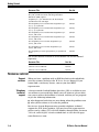


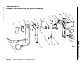

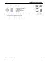
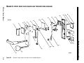
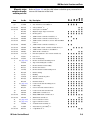
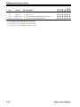
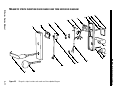

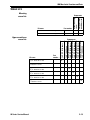


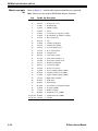
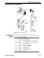
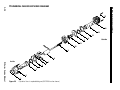
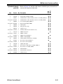
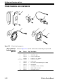


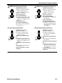
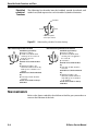
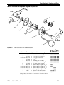
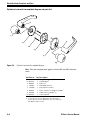
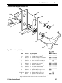
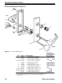

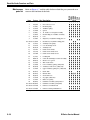


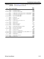
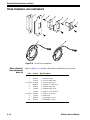
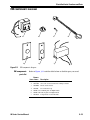


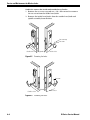
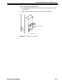

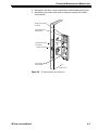

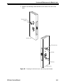


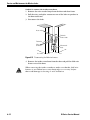

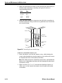

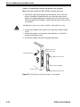


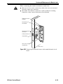
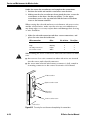


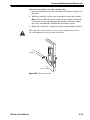

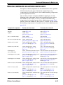


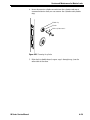
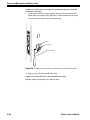
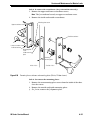


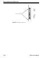
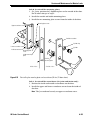

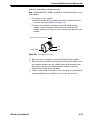
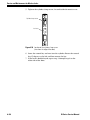
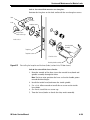


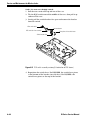


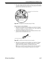
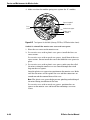


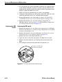

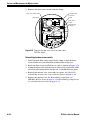
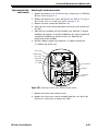


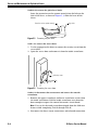

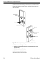

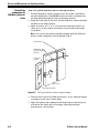

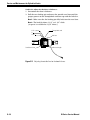

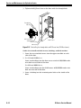
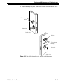
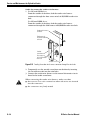
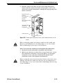

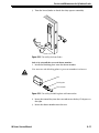
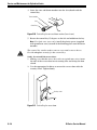


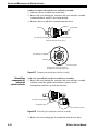

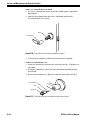
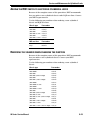

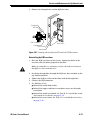
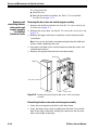


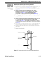

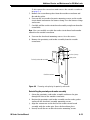


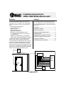


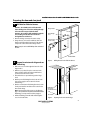
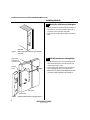

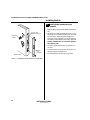
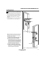

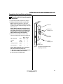
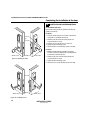
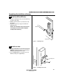
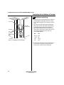

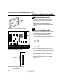
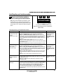

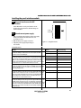
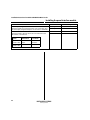


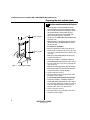

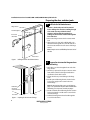
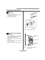
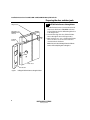

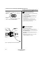


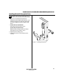
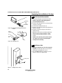

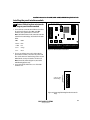

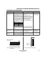


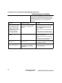
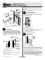


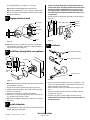
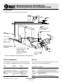


![B.A.S.I.S. G Service Manual [T63300]](http://vs1.manualzilla.com/store/data/006016632_1-3a9c260c4bb4c6128d680c6e76b28a8d-150x150.png)
![H Series Service Manual [T61964B]](http://vs1.manualzilla.com/store/data/007250209_1-ffc47db44ab35de2d6a65a65368d3859-150x150.png)