1
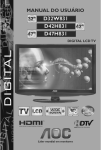
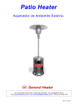
TERRACE AND PATIO HEATER
HLB-2400/ 2650 SERIES
INSTALLATION AND OPERATION
GUIDE
INDEX
General and specifications ………………1
Security and caution …………………….. 1,2
Tools and accessories required …………2
Assembly instructions …………………… 3
Verifying the connections ……………….. 4
Choosing a location for the heater ……… 5
Operation ………………………………….. 5
Storage and maintenance ……………….. 6
Trouble Shooting Guide ……………… 7
Carefully read the owners manual and all safety information
before assembling and operating the heater
THIS APPLIANCE IS APPROVED FOR
OUTDOOR USE ONLY
AZ PATIO HEATERS
8850 N 91 ST AVENUE
BLDG C, SUITE 25
PEORIA, 85345
"For parts and troubleshooting help please call 888-775-1330
or visit our website at www.azpatioheaters.com"
This appliance is an infrared transportable heater.
The burner is controlled and adjusted by the gas control knob.
Gas supply is controlled by the valve on the gas cylinder.
The burner is made of stainless steel.
reflector above.
Heat diffusion is assisted by the
Technical specification:
●
●
●
●
●
●
Operating pressure :
Maximum output :
Minimum output :
Gas consumption at HIGH :
Approx. weight ;
Burner orifice size :
11” W.C.
45.000 BTU/h
25.000 BTU/h
1 kg/h
27 kg
1.9 mm
FOR YOUR SAFETY
1. If you smell gas :
a. Close gas supply at cylinder valve.
b. Extinguish all open flame
c. Proceed to a leak test with a soapy water solution (50% part soap/ 50% part
water)
d. If bubbles are detected, retighten connections. If no leaks are detected,
open gas valve at cylinder and verify if you smell gas.
e. If you still smell gas, shut-off heater completely and gas valve at cylinder.
Call AZ Patio Heaters at 888-775-1330 or contact a gas appliance
service center.
2. Never store or handle gas, or any other flammable vapors or liquids in the
vicinity of your Patio Heater or any gas appliance.
CAUTION
Faulty installation, modifications, repairs or maintenance to the appliance may
cause injury or damage to property, and will void the warranty.
Carefully read this User Guide before assembling and setting up the heater.
Keep this guide for future reference.
-1-
CAUTION
●
●
●
●
●
●
●
●
●
●
●
●
●
●
●
●
●
DO NOT operate the heater in an explosive environment. Keep this
appliance away from areas where you have stored gas, or other vapors and
flammable liquids.
Before use, verify that no parts are damaged, inspect gas hose.
Never modify, this appliance in any way, or it will void the warranty.
Never use the heater without the reflector shield .
Respect minimum clearance from combustibles as seen on page 6.
Always place heater on a leveled, stable and hard surface.
Only use this heater outdoors.
Never clean with abrasive, corrosive or flammable cleaners.
Do not paint the heater or any of its parts.
When fully assembled proceed to a leak test, and every time you
disconnect the hose, before lighting up the heater.
A leak test must be performed before operating the appliance.
To leak test, use a 50/50 mix of each water and soap in a spray bottle.
NEVER LEAK TEST with an open flame or while smoking.
The gas cylinder must be closed at all times when not using the heater.
Children and adults should be made aware of hot surfaces on the heater.
Clothing and other accessories or object are not to be hung on the heater,
laid on or near it to dry.
Do not obstruct the ventilation opening (hand hole) on cylinder cover.
Installation, maintenance and repair of this heater should always be performed
by a qualified gas technician.
PARTS LIST
1 Base
2 Cylinder cover
3 Ventilation opening
4 Post
5 Gas control
6 Burner assembly
7 Flame screen
8 Reflector
TOOLS AND EQUIPMENT REQUIRED
10 and 13mm wrench,
Philips screwdriver, medium blade
Leak test solution: MIX 50/50 water and soap
1 Propane cylinder (not supplied), with QCC 1 valve
-2-
ASSEMBLY INSTRUCTIONS
A.
Attach the 3 vertical supports to the base
using the 3 bolts M8 x 15.
B
C
Fasten post to the vertical supports
with 6 bolts M6 X 35 and 6 nuts M6.
Slide cylinder cover on post.
D
Slide hose through bottom of post and
connect to burner head.
Then attach burner to the post with the 4
Philips mechanical screws M6x10mm.
-3-
E
Place a steel washer over each bolt on
the burner top.
Lay reflector over the burner top bolts
add another steel washer to each bolt
and screw wing nuts to fasten reflector
to the burner.
F
Install a full gas cylinder on the base.
Connect the gas regulator hose to the QCC1 cylinder
valve by turning the knob clockwise manually.
Do not use a tool, tighten firmly by hand.
Replace cylinder cover.
LEAK TEST
Now that the heater is assembled, for your safety you must perform a leak test of all
connections and hoses.
Mix in a spray bottle equal parts of water and soap.
1. Ensure that the heater gas control knob is fully closed by turning
completely clockwise
2. Open cylinder valve.
3. Apply the solution generously to all connections and hoses.
If you detect bubbles, there is a leak. Close cylinder valve completely. Retighten the
leaking connection and repeat leak test process.
If the leak cannot be repaired permanently, close cylinder valve completely and contact
AZ patio heaters at 888-775-1330 or a qualified gas technician.
-4-
A SAFE LOCATION FOR THE HEATER
CAUTION
When objects are left under a heater in operation, they will be subject to radiant heat
and may be damaged.
● The principal application of this heater is to give the comfort of heat to pools, patios,
spa areas, terraces, work areas, etc.
This heater is approved for outdoor use only.
● Provide fresh air ventilation at all times
● Respect minimum clearances to combustibles as shown in the figure below.
● Install heater on a level, solid and stable ground.
● Do not install in an explosive environment. Keep away from areas where gas,
vapors or flammable liquids are stored or used.
● In case of high winds, shut-off the heater completely and the cylinder gas valve.
Remove reflector dome.
● Do not move the heater when hot.
CLEARANCES FROM COMBUSTIBLES
Respect clearances as shown:
- Sides of reflector : 24 inches
- Above reflector : 18 inches
OPERATION
TO LIGHT-UP
1. Open valve at gas tank.
2. From OFF position, depress knob, turn 90° counter clockwise and hold.
3. While depressing control knob, for at least 45 seconds, then press spark igniter
button to light up burner. You may have to push it more than once. When flame is
visible, keep control knob depressed
for 30 seconds.
If igniter fails to light the burner after 8 seconds, release control knob, turn to
OFF and wait 5 minutes.
If gas hose is connected for the first time or to a refilled tank, it will take about
1 minute to purge the line to empty its air and to allow gas to reach the burner.
4. Release control knob, burner flame should stay lit.
If not, repeat steps 1 to 4 or you may light with a match.
5. Turn control knob to HI for maximum heat.
TO TURN OFF
1. Push and turn control knob clockwise to OFF
2. Turn off valve at gas tank.
-5-
STORAGE
When heater is not in use for a prolonged period of time, remove gas cylinder.
Verify that the gas valve is closed tightly.
Do not store the gas cylinder indoors.
Store gas cylinder in a well ventilated area.
PREVENTIVE CARE AND MAINTENANCE
Once a year, the heater should be inspected for debris, insects, or spider webs that
could obstruct the burner or pilot tube. The burner area is likely to attract spiders. This
may prevent gas getting to damage the burner if it is not kept clean of debris.
HAVE HEATER INSPECTED IF ……..
● You smell gas combined with yellow tipped flames on burner.
● Heater does not provide expected heat capacity.
● Burner makes little popping sounds while operating.
This sound is normal when turning off the heater.
PRECAUTIONS
● Verify periodically for leaks in the system, or immediately when you smell gas.
● In case a leak is detected, put out all open flame in the area.
● Never leak test while smoking or with an open flame .
● If you cannot repair a leak, turn off gas supply at the cylinder valve and contact
AZ Patio Heaters at 888-775-1330 or a qualified technician.
● Do not alter or modify in any way this heater or it will void the warranty..
● Contact the manufacturer for replacement parts.
● The installation of this appliance should be done by a certified gas technician in
accordance with all local, building and municipal codes.
● Warranty is for 1 year from the date of purchase and is verified by the purchase receipt.
Without a receipt, no replacement parts will be provided.
-6-
TROUBLE SHOOTING GUIDE
If you are having this
problem
If this condition exists:
You will need to do the following:
1. Cylinder valve may be
OFF.
►Open valve at cylinder. Turn cylinder
valve in counter-clockwise direction.
2. LPG tank empty
►Refill LPG tank
3. Orifice blocked
►Clean Spider web or other
blockage, or replace orifice.
4. Loose connection
Burner flame will not stay on
►Check all fittings
5. Thermocouple failed ►Replace thermocouple
6. Gas leak in line
►Turn tank off. Wait 5 minutes.
Check fuel line connections.
Reinsert regulator tighten firmly and
re-try.
7. Lack of fuel pressure
Burner flame will not light
Igniter does not work
1.
Pressure is low
► Nearly empty fuel tank
► Tank is near empty
2.
Control not ON
► Turn valve to ON and push in.
3.
Orifice blocked
► Remove and clean out.
Electrode might have
accumulated black soot
-7-
► Light the burner manually
or clean the electrode, check wire
connections and re-try..