1
User Manual
SRP-150
Thermal Printer
Rev. 1.05
http://www.bixolon.com
SRP-150
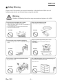
■ Safety Warning
Proper use of this product can prevent hazardous or physical harm. Make sure all
following instructions are followed when using this product.
Warning
Violation of following instructions may cause serious injure or risk of life.
Do not connect several plugs into a socket.
Please use the adapter provided.
• High temperature or fire may cause a danger.
• Use the plug before wiping it in case of contamination of
foreign material or water.
• Do not insert the plug into a socket with loosened slots.
• Use approved multi-slots socket.
• Other adapter may cause a danger.
ONLY SUPPLIED ADAPTER
Prohibit
Prohibit
Do not pull the power cord when unplugging.
• Power cord may cause a fire or malfunction resulting in
harms.
Keep it in plastic bag and keep out of reach
of children.
• Plastic bag capped on the children’s heads may
cause hazard.
Prohibit
Prohibit
Do not insert or remove the plug with wet hands.
• May case electric shock.
Do not bend the power cord or put heavy things on i
t, ensuring no damage to the cord.
• May cause a fire.
Prohibit
Prohibit
Rev. 1.05
-2-
SRP-150
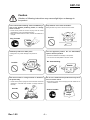
Caution
Violation of following instructions may cause slight injure or damage to
the product.
Power off and take following actions immediately in
case of the product producing smoke, or strange
smell or sound.
Keep the drier out of reach of children.
Eating the drier may result in serious harm to health.
• Power off the printer and remove the plug from the socket
immediately in case of exceptional situation.
• Make sure whether there is smoke, and take it to distributor f
or repair.
Prohibit
Plug Prohibit
PRINTER
Install the product in a stable place.
Use the approved product. Do not disassemble,
repair or alter the product.
• Falling down may cause damage to the product or
injure.
• Consult the distributor for damage to the product.
• Do not touch the sharp blade on the auto cutter.
PRINTER
No disassembling
Prohibit
PRINTER
Note that no water or foreign material is allowed in
the printer body.
Do not use a malfunctioned product that may cause
a fire or electric shock.
• Power off the printer, unplug from the socket and contact the
distributor in case that there is water or foreign material in
the body.
• Power off the printer, remove the plug from the socket and co
ntact the distributor.
Prohibit
Socket Prohibit
PRINTER
Rev. 1.05
PRINTER
DEALER
-3-
SRP-150
Copyright BIXOLON
(C) Copyright BIXOLON Co., Ltd.
All rights reserved
Partial or total duplication, reproduction or translation of the User Manual and product or
convert to any electronic media or readable form without prior written permission is
prohibited. The errors related to printing or technology in the User Manual and product are
subject to change without prior notice.
BIXOLON LOGO is the registered trademark of BIXOLON.
For the distributor and user’s attention, this machine has the same model as the one
commercially registered EMI (electromagnetic interference). If you sell or purchase by
mistake, please change back into the household type.
We at BIXOLON maintain ongoing efforts to enhance and upgrade the functions and
quality of all our products. In following, product specifications and/or user manual content
may be changed without prior notice.
■ WEEE (Waste Electrical and Electric Equipment)
The product marked with this symbol or relevant text indicates that the product
cannot be discarded with other family wastes at the end of its life. Please
separately dispose of it from other wastes to avoid any harm to the environment
and human being. Observe the Recycling Policy to make full use of the limited
resource. The household user can contact the distributor or local service office
for any information about proper disposal methods and premises. The commercial user
can contact the supplier or dispose as per the terms provided in the Purchase Contract.
This product cannot be disposed with other commercial wastes.
■ Symbol material: PET
Rev. 1.05
-4-
SRP-150
(3)
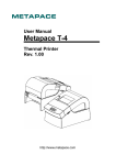
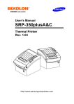
■ Introduction
(2)
(1)
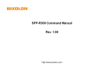
Assembly Name
(1) COVER PAPER
(2) ROLLER ASS’Y
(3) PAPER
(4) COVER CUTTER
(5) COVER FUCNTION
(6) CASE MAIN
(7) CASE LOWER
(8) COMMUNICATION PORT
- P ARALLEL/SERIAL
(9) CASH DRAWER (RJ-11)
(10) USB COMMUNICATION
Rear
(8)
(4)
Rear
(5)
(6)
(7)
(9)
(10)
SRP-150P/S
(9)
SRP-150U
SRP-150P/S,SRP-150U The printer is a banking peripheral device and can be used with
ECR, POS etc.
Its main features are shown as follows:
1. High speed printing;
2. Thermal printing with low noise;
3. RS-232 series interface(SRP-150), IEEE1284 parallel interface(SRP-150P),
USB2.0 interface(SRP-150U).
4. Reception of data is possible via Data buffer, even in printing process.
5. The Document Image Processing button enables selection of different printing density.
Please read this User Manual carefully before using SRP-150P/S, SRP-150U.
※ Note
The socket is required near the machine for use.
Rev. 1.05
-5-
SRP-150
■ Table of Contents
1. Installation and basic operations ·················································································7
1-1 Unpacking······················································································································7
1-2 Installation Site ··············································································································7
1-3 Operation Panel·············································································································8
2. Connection ·····················································································································9
2-1 AC Adapter Connection ·································································································9
2-2 Interface Connection ···································································································10
2-2-1 SRP-150S Serial Interface ···················································································· 11
2-2-2 SRP-150P Parallel Interface ·················································································12
2-2-3 SRP-150U USB Interface······················································································12
2-2-4 Cash Drawer Cable Connection (Option)······························································13
3. DIP Switch Setting ·······································································································14
3-1 Setting the DIP Switches ·····························································································15
3-1-1 Setting the DIP switch (RS-232C Serial Interface) ················································15
3-1-2 Setting the DIP switch (IEEE1284 Parallel, USB2.0 Interface) ·····························15
3-2 Setting the Memory Switches ······················································································15
4. Paper Loading··············································································································18
5. Sample Test ··················································································································19
6. Hexadecimal Dumping ································································································20
7. Specification ················································································································21
8. WINDOWS Driver Setting ····························································································22
8-1 Serial (RS-232C) Interface Model Windows Driver Setting ·········································22
8-2 Parallel (IEEE1284) Interface Windows Driver Setting ················································23
8-3 USB2.0 Interface Model Windows Driver Setting ························································23
9. Control Command List ································································································24
10. Summary of Control Command ················································································25
Rev. 1.05
-6-
SRP-150
1. Installation and basic operations
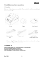
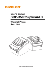
1-1 Unpacking
Make sure all following items are available. Please contact the distributor immediately in
case of loss or damage.
Printer
Cable interface
USB
User Manual
Paper
Power cord
Cable interface
Serial, parallel cable
- Only one of the following cable interfaces is provided according to the model you
purchase, USB, parallel or serial interface.
1-2 Installation Site
Keep the product away from the high temperature or direct sunlight.
Do not place it at the place full of moisture.
Keep it at a stable place and away from shock.
Leave enough space for the printer for convenient use.
Rev. 1.05
-7-
SRP-150
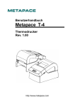
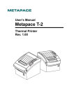
1-3 Operation Panel
The Panel consists of one button and two indicators.
Button
FEED
To print one paper, press the FEED button.
To continuously print, press and hold the FEED button.
Indicator
The indicator indicates the state of the printer.
POWER (green)
The indicator lights when the printer powers on.
ERROR (red)
The indicator lights when the paper is used out, or the printer is in idle,
or the cover opens.
Rev. 1.05
-8-
SRP-150
2. Connection
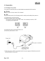
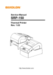
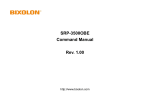
2-1 AC Adapter Connection
It is required to used the power cord and adapter accompanied with the printer.
※ Warning
Improper power unit may cause a fire or hazard.
※ Note
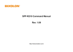
1. Operate the product in the following orders for safety and durability after power on.
1) Connect power cord to the printer.
2) Identify the power switch of the printer.
- The product is delivered in the “OFF” state. It is necessary to switch to “ON”.
- The printer power switch OFF
OFF
ON
3) Connect the power cord with the power unit.
4) Place the power switch to “ON”
Power Unit
Cable power connection
2. When the printer is "ON”, the repeated switch of power supply will affect the service life
and performance of the printer.
Rev. 1.05
-9-
SRP-150
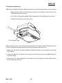
2-2 Interface Connection
USB, serial or parallel interface cable is required for connecting the printer to the computer.
- Make sure the power of the printer and computer is switched on, then connect the
cable interface to the printer.
- In the case of serial and parallel cable, assemble as the following picture shown.
- Connect the computer to the other end.
25 Pin Female Type
Make sure the power unit is removed from the plug of the device when the printer powers
on or off, otherwise damage may be caused to the printer and power unit.
1. Make sure the printer has been switched off and the power unit removed from the plug
of the device.
2. Check the label on the power unit to make sure the power plug is compatible with the
required voltage.
3. Connect the DC cable connector of the power unit to the power connector of the printer
as the following instruction.
Rev. 1.05
- 10 -
SRP-150
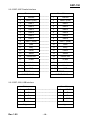
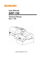
2-2-1 SRP-150S Serial Interface
Printer
Case Main
1
-
1
-
2
TXD
---------------------
2
RXD
3
RXD
---------------------
3
TXD
4
DSR
---------------------
4
DTR
5
GND
---------------------
5
GND
6
DTR
---------------------
6
DSF
7
CTS
---------------------
7
RTS
8
RTS
---------------------
8
CTS
9
-
9
-
Shield
---------------------
9PIN MALE
Rev. 1.05
Shield
9 PIN FEMALE
- 11 -
SRP-150
2-2-2 SRP-150P Parallel Interface
Printer
Case Main
1
nStrobe
----------------
1
nStrobe
2
Data 0 (LSB)
----------------
2
Data 0 (LSB)
3
Data 1
----------------
3
Data 1
4
Data 2
----------------
4
Data 2
5
Data 3
----------------
5
Data 3
6
Data 4
----------------
6
Data 4
7
Data 5
----------------
7
Data 5
8
Data 6
----------------
8
Data 6
9
Data 7 (MSB)
----------------
9
Data 7 (MSB)
10
nAck
----------------
10
nAck
11
Busy
----------------
11
Busy
12
Perror
----------------
12
Perror
13
Select
----------------
13
Select
14
nAutoFeed
----------------
14
nAutoFeed
15
nFault
----------------
15
nFault
16
nInit
----------------
16
nInit
17
nSelsctIn
----------------
17
nSelsctIn
----------------
18~25
18~25
GND
FGND
----------------
25 PINE MALE
GND
FGND
25 PINE MALE
2-2-3 SRP-150U USB Interface
Printer
1
VBUS
-----------------------------------
1
VBUS
2
D-
-----------------------------------
2
D-
3
D+
-----------------------------------
3
D+
4
GND
-----------------------------------
4
GND
Shield
B type
Rev. 1.05
Case Main
-----------------------------------
- 12 -
Shield
A type
SRP-150
2-2-4 Cash Drawer Cable Connection (Option)
Pin No.
1
2
3
4
5
6
Rev. 1.05
Description
Frame GND
Drawer Kick-Out Driver Signal #1
Drawer Open / Close Signal
+12V
Drawer Kick-Out Driver Signal #2
Signal GND
- 13 -
Direction
Output
Input
Output
-
SRP-150
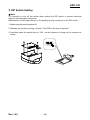
3. DIP Switch Setting
※ Note
It is required to turn off the printer when setting the DIP switch to prevent electrical
rejection and damage to the printer.
Replacement of the contact device or the printing density can be set on the DIP switch.
1. Make sure the printer powers off.
2. Release the tray by removing 3 screws. The PCB on the tray is exposed.
3. Note that when the switch turns to “ON”, use the tweezer or sharp tool to unscrew the
switch.
Rev. 1.05
- 14 -
SRP-150
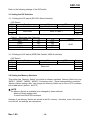
Refer to the following settings of the DIP switch.
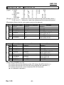
3-1 Setting the DIP Switches
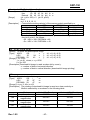
3-1-1 Setting the DIP switch (RS-232C Serial Interface)
• DIP Switch
SW
1-1
1-2
1-3
1-4
Function
Auto Cutter
ON
Disable
Reserved
Baud Rate
OFF
Enable
Default
OFF
OFF
OFF
Refer to Table 1
• Table 1 – Baud rate (bps) Selection
Transmission Speed
1-3
9600
OFF
19200
OFF
38400
ON
115200
ON
1-4
OFF
ON
OFF
ON
Default
9600
3-1-2 Setting the DIP switch (IEEE1284 Parallel, USB2.0 Interface)
• DIP Switch
SW
1-1
1-2
1-3
1-4
Function
Auto Cutter
ON
Disable
OFF
Enable
Reserved
Default
OFF
-
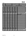
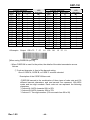
3-2 Setting the Memory Switches
This printer has “Memory Switch” set which is software switches. Memory Switch set has
“MSW1”, “MSW2”, “MSW8”, “MSW9” “Customize value”, “Serial communication condition”.
“Memory Switch setting utility” can change the Memory Switch set to ON or OFF as shown
in the table below. (default : all OFF)
※ NOTE
- The Memory Switch is available to be changed by three methods.
- Memory Switch setting utility.
- Control from BXL/POS command.
Settings of the Memory Switch are stored in the NV memory : therefore, even if the printer
is turned off, the settings are maintained.
Rev. 1.05
- 15 -
SRP-150
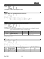
MSW2
Switch
1
2
3~8
Function
Reserved
Auto Cutter Function
Code Page Selection
ON
OFF
Fixed to OFF
Full Cutting
Partial Cutting
Refer to following Table
MSW2-8
MSW2-7
MSW2-6
MSW2-5
MSW2-4
MSW2-3
OFF
OFF
OFF
OFF
OFF
OFF
OFF
OFF
OFF
OFF
OFF
OFF
OFF
OFF
OFF
OFF
ON
ON
ON
ON
ON
ON
ON
ON
ON
ON
ON
ON
ON
ON
ON
ON
OFF
OFF
OFF
OFF
OFF
OFF
OFF
OFF
OFF
OFF
OFF
OFF
OFF
ON
ON
ON
ON
ON
ON
ON
ON
OFF
OFF
OFF
OFF
OFF
OFF
OFF
OFF
ON
ON
ON
ON
ON
ON
ON
ON
OFF
OFF
OFF
OFF
OFF
OFF
OFF
OFF
OFF
ON
ON
ON
ON
OFF
OFF
OFF
OFF
ON
ON
ON
ON
OFF
OFF
OFF
OFF
ON
ON
ON
ON
OFF
OFF
OFF
OFF
ON
ON
ON
ON
OFF
OFF
OFF
OFF
ON
OFF
OFF
ON
ON
OFF
OFF
ON
ON
OFF
OFF
ON
ON
OFF
OFF
ON
ON
OFF
OFF
ON
ON
OFF
OFF
ON
ON
OFF
OFF
ON
ON
OFF
OFF
ON
ON
OFF
OFF
ON
ON
OFF
OFF
ON
OFF
ON
OFF
ON
OFF
ON
OFF
ON
OFF
ON
OFF
ON
OFF
ON
OFF
ON
OFF
ON
OFF
ON
OFF
ON
OFF
ON
OFF
ON
OFF
ON
OFF
ON
OFF
ON
OFF
ON
OFF
OFF
OFF
OFF
OFF
OFF
OFF
OFF
OFF
OFF
OFF
OFF
OFF
OFF
OFF
OFF
OFF
OFF
OFF
OFF
OFF
OFF
OFF
OFF
OFF
OFF
OFF
OFF
OFF
OFF
OFF
OFF
OFF
ON
ON
ON
ON
ON
Rev. 1.05
- 16 -
Page 0
Page 1
Page 2
Page 3
Page 4
Page 5
Page 16
Page 17
Page 18
Page 19
Page 21
Page 22
Page 23
Page 24
Character Table
437 (USA,standard Europe)
Katakana
850 (Multilingual)
860 (Portuguese)
863 (Canadian-French)
865 (Nordic)
1252 (Latin I)
866 (Cyrillic #2)
852 (Latin 2)
858 (Euro)
862 (Hebrew DOS code)
864 (Arabic)
Thai42
1253 (Greek)
Page 25
Page 26
Page 27
Page 28
Page 29
Page 30
Page 31
Page 32
Page 33
1254 (Turkish)
1257 (Baltic)
Farsi
1251 (Cyrillic)
737 (Greek)
775 (Baltic)
Thai14
Hebrew Old code
1255 (Hebrew Newcode)
Page 34 Thai11
Page 35 Thai18
Page 36 855 (Cyrillic)
Page 37 857 (Turkish)
Page 38 928 (Greek)
Page 39 Thai16
Reserved
Reserved
Reserved
Page 43 (PC852e)
Page 44 (PC864e)
Page 45 (PC865/PC1252e)
Reserved
Page 47 ISO 8859-1(Latin I)
SRP-150
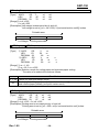
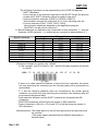
MSW9
Switch
1
2~4
5~8
MSW9-8
OFF
OFF
OFF
OFF
OFF
OFF
OFF
OFF
ON
ON
ON
ON
ON
ON
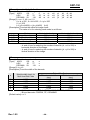
MSW10
Switch
1
2
3
4~5
6~8
MSW10-8
OFF
OFF
OFF
OFF
ON
ON
ON
ON
Rev. 1.05
Function
Language Selection
Reserved
International Character Set
Selection
MSW9-7
OFF
OFF
OFF
OFF
ON
ON
ON
ON
OFF
OFF
OFF
OFF
ON
ON
MSW9-6
OFF
OFF
ON
ON
OFF
OFF
ON
ON
OFF
OFF
ON
ON
OFF
OFF
ON
Korean/Chinese
-
Refer to following Table
MSW9-5
OFF
ON
OFF
ON
OFF
ON
OFF
ON
OFF
ON
OFF
ON
OFF
ON
Function
Reserved
Font Size Selection
Print Density
Reserved
Partial Cut Step Selection
MSW10-7
OFF
OFF
ON
ON
OFF
OFF
ON
ON
OFF
ENG
Fixed to OFF
International Character Set
0. USA
1. France
2. Germany
3. UK
4. Denmark
5. Sweden
6. Italy
7. Spain
8. Japan
9. Norway
10. Denmark II
11. Spain II
12. Latin America
13. Korea
ON
OFF
Fixed to OFF
Font C(9x24)
Font A(12x24)
Dark
Normal
Fixed to OFF
Refer to following Table
MSW10-6
OFF
ON
OFF
ON
OFF
ON
OFF
ON
Step
85 Steps (Default)
82 Steps
83 Steps
84 Steps
86 Steps
87 Steps
88 Steps
89 Steps
- 17 -
SRP-150
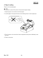
4. Paper Loading
Please use the standard paper.
※ Note
It is important to power off the printer in the process of paper loading.
1. Open the paper cover and take out all used paper.
2. Load the paper in the proper direction as the following shown in case of paper jam.
3. Place the paper to the extent that it can be exposed from the printer. Additionally, close
the cover.
4. Power on the printer.
Rev. 1.05
- 18 -
SRP-150
5. Sample Test
1. Sample Printing Test
* Sample Test Start-up
After loading paper and close the cover and the PAPER FEED button pressed and held,
the sample test will start upon power on. The self-test will conduct printing according to the
existing setting of the following information available.
- Software version control
- DIP switch state
* Preparation State
The printer will print the message “Please press the FEED BUTTON” after printing the
existing setting state. LED flickering indicates the printer is in the preparation state for
printing test.
2. Self-test Completion
Upon the printing test completion, the printer will print " ** TEST COMPLETED **”,
indicating the test is finished.
It is necessary to restart printing if the self-test is not over yet.
Rev. 1.05
- 19 -
SRP-150
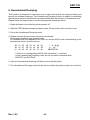
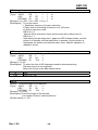
6. Hexadecimal Dumping
This function is designed for advanced user to send and receive the data accurately and
identify the software problems. The Hexadecimal Dumping function is helpful for searching
special terms because all data and command statements are printed in hexadecimal form.
Please follow the steps below to use the hexadecimal dumping function.
1. Open the paper cover after the printer powers off.
2. With the FEED button pressed and held, power off the printer, then close the cover
3. Go to the Hexadecimal Dumping mode.
4. Please execute the item where the printer sends data.
Printer prints all data in two separate rows.
The hexadecimal code appears in the first row, and the ASCII code corresponding to the
hexadecimal code in the second row.
1B 21 00 1B 26 02 40 40
1B 25 01 1B 63 34 00 1B
41 42 43 44 45 46 47 48
.!..&.@@
. % . . c4 . .
ABCDEFGH
- If there is no corresponding ASCII code, the period (.) is printed.
- In the Hexadecimal Dumping mode, do not use other commands than
DEL EOT and DLE ENQ.
5. Upon the hexadecimal dumping is finished, power off the printer.
6. The Hexadecimal Dumping mode will be removed when the printer powers on next time.
Rev. 1.05
- 20 -
SRP-150
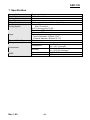
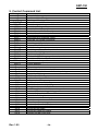
7. Specification
Printing Method
Resolution
Printing Width
Paper Width
Strings Per Line
Printing Speed
Paper
Receive Buffer Size
Voltage
Environment
MCBF
Rev. 1.05
Thermal printing
203Dpi (8 dot/mm)
48mm
58.0±0.5mm
32 (Font A) (12x24) / 42 (Font C) (9x24)
About 19 lines/sec
Max. 65 mm/sec
at 25℃/printing duty 12.5%
Thickness: 0.062 ~ 0.075mm
Roller size: Ø80mm
Paper size
- Internal diameter: Ø12mm (0.47”)
- External diameter: Ø18mm (0.71”)
4K bytes
100~240 VAC
0 ~ 45℃ (operating)
Temperature
-20 ~ 60℃ (storage)
10 ~ 80% RH (operating)
Humidity
10 ~ 90% RH (storage)
Mean time to repair 20,000,000 line
Thermal tab
100km
- 21 -
SRP-150
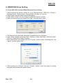
8. WINDOWS Driver Setting
8-1 Serial (RS-232C) Interface Model Windows Driver Setting
1. After executing the proudct setting CD, go to Thermal Printer > SRP-150 > Drivers >
Windows Driver > Drivers folder > exectute SRP-150_WIN_Vx.x.xx.exe
2. Select “Next” from the window at the initial setting.
3. Install Select “Install” from the “Ready to Install the Program” window.
4. Select a serial port from the "Select Port Type”, and then select “Next”.
(Fig 1)
5. The computer will reboot after selecting an example from the “Question”.
6. Upon reboot, operate as follows: Start > Setting > Printer and Scan > BIXOLON SRP150 Icon > Right click > Select “Property”.
7. After selecting the “Port” button from the “Property” window, select “Self-diagnosis” and
“Agree”, and then select “OK”.
8. After selecting the “General” from the “Property” window, select test page for printing
and make sure whether the speed is faster.
Rev. 1.05
- 22 -
SRP-150
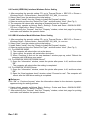
8-2 Parallel (IEEE1284) Interface Windows Driver Setting
1. After executing the proudct setting CD, go to Thermal Printer > SRP-150 > Drivers >
Windows Driver > Drivers folder > exectute SRP-150_WIN_Vx.x.xx.exe
2. Select “Next” from the window at the initial setting.
3. Install Select “Install” from the “Ready to Install the Program” window.
4. Select a serial port from the "Select Port Type”, and then select “Next”. (See Fig 1)
5. The computer will reboot after selecting an example from the “Question”.
6. Upon reboot, operate as follows: Start > Setting > Printer and Scan > BIXOLON SRP150 Icon > Right click > Select “Property”.
7. After selecting the “General” from the “Property” window, select test page for printing
and make sure whether the speed is faster.
8-3 USB2.0 Interface Model Windows Driver Setting
1. After executing the proudct setting CD, go to Thermal Printer > SRP-150 > Drivers >
Windows Driver > Drivers folder > exectute SRP-150_WIN_Vx.x.xx.exe
2. Select “Next” from the window at the initial setting.
3. Install Select “Install” from the “Ready to Install the Program” window.
4. Select a serial port from the "Select Port Type”, and then select “Next”. (See Fig 1)
5-1. For WINDOW 98/ME
① The computer will reboot after set as the above.
② Upon reboot, the printer will restart after shut down.
③ When “Continue to find out the new hardware” window pops up, select “Reboot the
computer with USB drive upon setup”.
5-2. For WINDOW 2000/VISTA/2008 Server/7
① Open the “Information” window, restart the printer after power it off, and then select
“OK”.
② The computer will reboot after the setting is completed.
5-3. For WINDOW XP/2003 Server
① Open the “Information” window, restart the printer after power it off, and then select
“OK”.
② Open the “New hardware check” window, select “Proceed to next”. The computer will
reboot after the USB driver setting is completed.
※ Reference
Click “OK” or “Continue Anyway” when the information related to the electronic signature
appears during the setting process.
6. Upon reboot, operate as follows: Start > Setting > Printer and Scan > BIXOLON SRP150 Icon > Right click > Select “Property”.
7. After selecting the “General” from the “Property” window, select test page for printing
and make sure whether the speed is faster.
Rev. 1.05
- 23 -
SRP-150
9. Control Command List
Command
HT
LF
CR
DLE EOT
ESC SP
ESC !
ESC $
ESC %
ESC &
ESC *
ESC ESC 2
ESC 3
ESC =
ESC ?
ESC @
ESC D
ESC E
ESC J
ESC R
ESC V
ESC \
ESC a
Esc d
Esc p
Esc t
Esc {
FS p
FS q
GS !
GS ( E
GS *
GS /
GS :
GS B
GS H
GS I
GS L
GS V
GS W
GS ^
GS f
GS h
GS k
GS v
GS w
Rev. 1.05
Name
Horizontal tab
To print and Line Feed
To print and Carriage Return
To send the real time status
To set the right side space of the characters
To set the printing mode
To set the absolute position
To select/cancel the defined character
To select the character to define
To set the bit image mode
To set/clear the underline mode
To set the 1/6 inches line space
To set the line space
To set the peripheral devices
To cancel the defined character
To initialize the printer
To set the position of horizontal tab
To select the highlight mode
To print and paper feed
To select the Multilanguage character set
To set/clear 90° clockwise rotated character
To set the relative position
To align position
To print and n-line feed
To generate pulse
To select the character code table
To select/clear vertical inverted character printing
To print the NV image
To define the NV image
To select the character size
To Customize NV memory area
To define download bit image
To print the download bit image
To begin/end macro definition
To set/clear black and with inversion mode
To select HRI character printing position
To transmit the printer ID
To set the left margin
To Select cut mode and cut paper
To set the output size
To run the macro
To select the font for HRI characters
To select the bar code height
To print the bar code
To print the raster bit image
To select the bar code size
- 24 -
SRP-150
10. Summary of Control Command
HT
[Name] Horizontal Tab
[Type]
ASCII
HT
HEX
09
Decimal
9
[Description] Set the horizontal tab if you want to use the print position.
LF
[Name] To print and line feed
[Type]
ASCII
LF
HEX
0A
DECIMAL 10
[Description] To print the data in the printer buffer and feed one line.
CR
[Name]
[Type]
To print and carriage return
ASCII
HT
HEX
0D
DECIMAL 13
[Description] To print the data in the printer buffer and move the printer head to the
beginning position of the line.
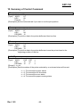
DLE EOT n
[Name] To send the real-time status
[Type]
ASCII
DLE EOT n
HEX
10
04
n
DECIMAL 16
4
n
[Range] 1 ≤ n ≤ 4
[Description] Real-time status of the printer selected by n as shown below will be sent.
n = 1: To transmit the printer status
n = 2: To transmit the off-line status
n = 3: To transmit the error status
n = 4: To transmit the paper-sensing status
Rev. 1.05
- 25 -
SRP-150
n = 1: Printer Status
Bit
Off/On
HEX
0
Off
00
1
On
02
2
Off
00
Off
00
3
On
08
4
On
10
5-6
7
Off
00
DECIMAL
0
2
0
0
8
16
0
Function
Not used. Fixed to Off
Not used. Fixed to On
Not used
On-line
Off-line
Not used. Fixed to On
Not defined
Not used. Fixed to Off
n = 2: Off-line Status
Bit
Off/On
HEX
0
Off
00
1
On
02
Off
00
2
On
04
Off
00
3
On
08
4
On
10
5
Off
00
6
Off
00
7
Off
00
DECIMAL
0
2
0
4
0
8
16
0
0
0
Function
Not used. Fixed to Off
Not used. Fixed to On
Cover is closed
Cover is open
Paper is not fed through the paper feed button
Paper is fed through the paper feed button
Not used. Fixed to On
Not used. Fixed to Off
Not used. Fixed to Off
Not used. Fixed to Off
n = 3: Error Status
Bit
Off/On
0
Off
1
On
2
3
Off
4
On
5
Off
6
Off
7
Off
DECIMAL
0
2
0
16
0
0
0
Function
Not used. Fixed to Off
Not used. Fixed to On
Not defined
Not used. Fixed to Off
Not used. Fixed to On
Not used. Fixed to Off
Not used. Fixed to Off
Not used. Fixed to Off
HEX
00
02
00
10
00
00
00
n = 4: Continuous Paper Detection Status
Bit
Off/On
HEX
DECIMAL
0
Off
00
0
1
On
02
2
Off,Off
00
0
2,3
On,On
0C
12
4
On
10
16
Off
00
0
5,6
On
60
96
7
Rev. 1.05
Off
00
0
Function
Not used. Fixed to Off
Not used. Fixed to On
Not used. Fixed to Off
Not used. Fixed to Off
Not used. Fixed to On
Paper roll sensor. Paper is detected.
Paper roll end is detected by the paper roll
sensor
Not used. Fixed to Off
- 26 -
SRP-150
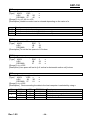
ESC SP n
[Name] To set the right side space of the characters
[Type]
ASCII
ESC SP
n
HEX
1B
20
n
DECIMAL 27
32
n
[Range] 0 ≤ n ≤ 255
[Description] To set the right side space of the characters
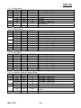
ESC ! n
[Name] To set the printer mode
[Type]
ASCII
ESC !
n
HEX
1B
21
n
DECIMAL 27
33
n
[Range] 0 ≤ n ≤ 255
[Description] Printer mode is set depending on the value of n as follows
Bit
0
1
2
3
4
5
6
7
Off/On
Off
On
Off
On
Off
On
Off
On
Off
On
Off
On
HEX
00
01
00
02
00
08
00
10
00
20
00
80
DECIMAL
0
1
0
2
0
8
0
16
0
32
0
128
Function
Font A(12x24) Selected
Font C(9x24) Selected
Not defined
Not defined
Not defined
Highlight mode is not set
Highlight mode is set
Double-height mode is not selected
Double-height mode is selected
Double-width mode is not selected
Double-width mode is selected
Not defined
Underline mode is not selected
Underline mode is selected
ESC $ nL nH
[Name] To set absolute position
[Type]
ASCII
ESC $
nL
nH
HEX
1B
24
nL
nH
DECIMAL 27
36
nL
nH
[Range] 0 ≤ nL ≤ 255
0 ≤ nH ≤ 255
[Description] To set the distance from the beginning point of the line and print the
characters. The distance from the beginning point for the printing position
means horizontal or vertical motion unit.
Rev. 1.05
- 27 -
SRP-150
ESC % n
[Name] To select/cancel user defined character set
[Type]
ASCII
ESC %
n
HEX
1B
25
n
DECIMAL 27
37
n
[Range] 0 ≤ n ≤ 255
[Description] To select/cancel user-defined character set.
User-defined character set is cancelled when LBS of n is 0,
User-defined character set is selected when LBS of n is 1.
ESC & y c1 c2 [x1 d1… d(y X x1)]…[xk d1…d(y X xk)]
[Name] To define user-defined characters
[Type]
ASCII
ESC
& y c1 c2 [x1 d1… d(y X x1)]…[xk d1…d(y X xk)]
HEX
1B
26 y c1 c2 [x1 d1… d(y X x1)]…[xk d1…d(y X xk)]
DECIMAL 27
38 y c1 c2 [x1 d1… d(y X x1)]…[xk d1…d(y X xk)]
[Range] y = 3
32 ≤ c1 ≤ c2 ≤ 126
0 ≤ x ≤ 12 (Font A (12×24))
0 ≤ d1… d(y × xk) ≤ 255
[Description] To define user defined characters.
y defines the number of bytes in the vertical direction.
c1 defines the code of beginning character, and c2 defines the end code.
x defines number of dots in horizontal direction.
ESC * m nL nH d1... dk
[Name] To set bit image mode
[Type]
ASCII
ESC
*
m
nL nH d1... dk
HEX
1B
2A
m
nL nH d1... dk
DECIMAL 27
42
m
nL nH d1... dk
[Range] m = 0, 1, 32, 33
0 ≤ nL ≤ 255 , 0 ≤ nH ≤ 3 , 0 ≤ d ≤ 255
[Description] Use m to select the bit image, where number of dots is defined by nL and
nH as shown below.
m
Mode
0
1
32
33
8-dot single-density
8-dot double-density
24-dot single-density
24-dot double-density
Rev. 1.05
Vertical Direction
Number
Density
of dots
8
67 DPI
8
67 DPI
24
200 DPI
24
200 DPI
- 28 -
Horizontal Direction (*1)
Density
Number of Data (k)
100 DPI
200 DPI
100 DPI
200 DPI
nL + nH × 256
nL + nH × 256
(nL + nH ( 256)(3)
(nL + nH ( 256)(3)
SRP-150
ESC – n
[Name] To set/clear underline mode
[Type]
ASCII
ESC n
HEX
1B
2D
n
DECIMAL 27
45
n
[Range] 0 ≤ n ≤ 2, 48 ≤ n ≤ 50
[Description] Underline mode is set or cleared depending on the value of n.
n
0,48
1,49
2,50
Function
Underline mode is cleared
Underline mode is selected (Dot thickness – 1)
Underline mode is selected (Dot thickness – 2)
ESC 2
[Name]
[Type]
To set the 1/6 inches line space
ASCII
ESC
2
HEX
1B
32
DECIMAL
27
50
[Description] To set the line space to 1/6 inches
ESC 3 n
[Name] To set the line space
[Type]
ASCII
ESC
3
n
HEX
1B
33
n
DECIMAL
27
51
n
[Range] 0 ≤ n ≤ 255
[Description] Line space will set to [n X vertical or horizontal motion unit] inches.
ESC = n
[Name] To set the peripheral devices
[Type]
ASCII
ESC =
n
HEX
1B
3D
n
DECIMAL 27
61
n
[Range] 0 ≤ n ≤ 255
[Description] Device sending the data to the host computer is selected by using n.
Bit
0
1
2-7
Rev. 1.05
Off/On
Off
On
-
HEX
00
02
-
DECIMAL
0
1
-
Function
Not defined
Printer is not recognized
Printer is recognized
Not defined
- 29 -
SRP-150
ESC ? n
[Name] To cancel the user defined character set
[Type]
ASCII
ESC ?
n
HEX
1B
3F
n
DECIMAL 27
63
n
[Range] 32 ≤ n ≤126
[Description] To cancel the user-defined character sets.
ESC @
[Name] To initialize the printer
[Type]
ASCII
ESC
@
HEX
1B
40
DECIMAL 27
64
[Description] This function purges the data in the buffer when the power is on or recovers
the printer mode.
ESC D n1...nk NUL
[Name] To set the horizontal tab position
[Type]
ASCII
ESC D
n1...nk
NUL
HEX
1B
44
n1...nk
00
DECIMAL 27
68
n1...nk
0
[Range] 1 ≤ n ≤ 255
0 ≤ k ≤32
[Description] To set the horizontal tab position
n defines the number of columns for the horizontal table from the beginning
point of the line.
k is the total number of horizontal tabs.
ESC E n
[Name] To set highlight mode
[Type]
ASCII
ESC E
n
HEX
1B
45
n
DECIMAL 27
69
n
[Range] 0 ≤ n ≤ 255
[Description] To select/clear highlight mode
Highlight mode is cleared when the LSB is 0.
Highlight mode is set when the LSB is 1.
ESC J n
[Name] To print and paper feed
[Type]
ASCII
ESC J
n
HEX
1B
4A
n
DECIMAL 27
74
n
[Range] 0 ≤ n ≤ 255
[Description] To print the data in the printer buffer and feed the paper.
n x vertical or horizontal motion unit inches
Rev. 1.05
- 30 -
SRP-150
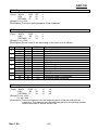
ESC R n
[Name] To select multilanguage character sets
[Type]
ASCII
ESC R
n
HEX
1B
52
n
DECIMAL 27
82
n
[Range] 0 ≤ n ≤ 10
[Description] To select the multilanguage character set with n.
Chinese version is not supported.
n
0
1
2
3
4
5
Rev. 1.05
Character set
U.S.A.
France
Germany
U.K.
Denmark Ⅰ
Sweden
n
6
7
8
9
10
- 31 -
Character set
Italy
Spain
Japan
Norway
Denmark Ⅱ
SRP-150
ESC V n
[Name] To set/clear 90° clockwise rotated character sets
[Type]
ASCII
ESC V
n
HEX
1B
56
n
DECIMAL 27
86
n
[Range] 0 ≤ n ≤ 1, 48 ≤ n ≤ 49
[Description] To set/clear 90° clockwise rotated character sets depending on the value of
n.
n
0,48
1,49
Function
To clear the 90° clockwise rotated character
To set the 90° clockwise rotated character
ESC \ nL nH
[Name] To set the relative printer position
[Type]
ASCII
ESC \
nL
nH
HEX
1B
5C
nL
nH
DECIMAL 27
92
nL
nH
[Range] 0 ≤ nL ≤ 255
0 ≤ nL ≤ 255
[Description] The beginning point is based on the current position by the horizontal and
vertical motion unit. This command sets the position from the current position.
[(nL + nH X 256) X (horizontal or vertical motion unit)].
ESC a n
[Name] Selective adjustment
[Type]
ASCII
ESC a
n
HEX
1B
61
n
DECIMAL 27
97
n
[Range] 0 ≤ n ≤ 2, 48 ≤ n ≤ 50
[Description] All data for aligning in a line have clear positions.
Adjustment type by the selection of n is as follows.
n
0,48
1,49
2,50
Adjustment
Left adjustment
Middle adjustment
Right adjustment
ESC d n
[Name] To print and n line feed
[Type]
ASCII
ESC D
n
HEX
1B
64
n
DECIMAL 27
100
n
[Range] 0 ≤ n ≤ 255
[Description] To print the data in the buffer and feed n lines
Rev. 1.05
- 32 -
SRP-150
ESC p m t1 t2
[Name]
To generate pulse
[Format]
ASCII
ESC
p
m
t1
t2
Hex
1B
70
m
t1
t2
Decimal
27
112
m
t1
t2
[Range]
m = 0, 1, 48, 49
0 ≤t1 ≤255, 0 ≤t2 ≤255
[Description]
Outputs the pulse specified by t1 and t2 to connector pin m as follows.
m
0, 48
1, 49
Connector pin
Drawer kick-out connector pin 2
Drawer kick-out connector pin 5
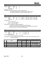
ESC t n
[Name] To select the character code table
[Type]
ASCII
ESC t
n
HEX
1B
74
n
DECIMAL 27
116
n
[Range] 0 ≤ n ≤ 5, n = 11, 255
[Description] n is used to select the character code table as follows.
Chinese version is not supported.
Page
n
0
0: PC437 [U.S.A., standard Europe]
1
1: Katakana
2
2: PC850 [Multilingual]
3
3: PC860 [Portuguese]
4
4: PC863 [Canadian-French]
5
5: PC865 [Nordic]
11
11: PC858 [Euro]
255
Space page
[Default value] n = 0
ESC { n
[Name] To select/cancel the vertical inverted printing mode
[Type]
ASCII
ESC {
n
HEX
1B
7B
n
DECIMAL 27
123
n
[Range] 0 ≤ n ≤ 255
[Description] To select or cancel the vertical inverted printing mode of the characters
- Vertical inverted mode is canceled when LSB is 0.
- Vertical inverted mode is selected when LSB is 1.
Rev. 1.05
- 33 -
SRP-150
FS p n m
[Name] NV image output
[Type]
ASCII
FS
p
n
m
HEX
1C
70
n
m
DECIMAL 28
112
n
m
[Range] 1 ≤ n ≤ 255, 0 ≤ m ≤3 , 48 ≤ m ≤ 51
[Description] NV image is printed in various sizes depending on the value of m.
m
0,48
1,49
2,50
3,51
Mode
Vertical dot density
Horizontal dot density
Normal
200 DPI
200 DPI
Double-width
200 DPI
100 DPI
Double-height
100 DPI
200 DPI
Quadruple
100 DPI
100 DPI
n is the NV image number defined by using FS q command.
m defines the image mode.
FS q n [xL xH yH d1 …dk]1…[xL xH yL yH d1…dk]n
[Name] To define NV image
[Type]
ASCII
FS q
n [xL xH yH d1 …dk]1…[xL xH yL yH d1…dk]n
HEX
1C 71
n [xL xH yH d1 …dk]1…[xL xH yL yH d1…dk]n
DECIMAL 28 113
n [xL xH yH d1 …dk]1…[xL xH yL yH d1…dk]n
[Range] 1 ≤ n ≤ 255, 0 ≤ nL ≤ 255, 0 ≤ d ≤ 255
0 ≤ xH ≤ 3 3 (when 1 ≤ xL+xH×256≤ 1023)
0 ≤ yL ≤ 1 (when 1≤yL+yH×256≤288)
k = (xL+xH×256) × (yL+yH×256)×8
Total defined data area = 1M bits(128K bytes)
[Description] The value of n is used to define the NV image. The value n is the defined
NV image number.
- xL and xH are used to set the NV image to (xL + xH(256))x8 dots in
horizontal direction.
- yL and yH are used to set the NV image to (yL + yH(256))x8 dots in
vertical direction.
GS ! n
[Name]
[Type]
To select the character size
ASCII
GS
!
n
HEX
1D
21 n
DECIMAL 29
33 n
[Range] 0 ≤ n ≤ 255
(1≤Vertical number of times≤8, 1≤Horizontal number of times≤8)
[Description] Bits 0 to 2 are used to select the height of the characters and the bits 4 to 7
are used to select the width of the characters.
Bit
0 ~1
4~5
Off/On
HEX
DECIMAL
Function
Height of the characters. Refer to the Table 2
Width of the characters. Refer to the Table 1
Table 1: Width of the characters
HEX
DECIMAL
Width
00
0
1 (normal)
10
16
2 (double-width)
Rev. 1.05
Table 2: Height of the characters
HEX
DECIMAL
Height
00
0
1 (normal)
01
1
2 (double-height)
- 34 -
SRP-150
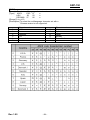
GS ( E pL pH fn [parameter]
[Name] To Customize NV memory area
[Description] Customize the NV user memory area. The table below explains the functions
available in this command. Executes commands related to the user setting
mode by specifying the function code fn.
fn
1
Format
GS ( E pL pH fn d1 d2
No.
1
Function
Changes into the user setting mode
Ends the user setting mode sessio.
(Performs a soft reset.)
2
GS ( E pL pH fn d1 d2 d3
2
3
GS ( E pL pH fn [a1 b18...b11]...
[ak bk8...bk1]
3
Sets value(s) for the memory switch
4
GS ( E pL pH fn a
4
Transmits the settings of the memory
switch to the host
[Notes] - pL, pH specifies (pL + pH x 256) as the number of bytes after pH (fn and
[parameter]).
- The user setting mode is a special mode to change the values in the NV user
memory with this command.
- In Function 2, the printer performs software reset. Therefore, the printer clears the
receive and print buffers, and resets all settings (user-defined characters, macros,
and the character style) to the mode in effect at power on.
- Frequent write commands by this command, may damage the NV memory.
Therefore, it is recommended to write to NV memory no more than 10 times a day.
- While processing this command, the printer is BUSY while writing data to the user
NV memory and stops receiving data. Therefore it is prohibited to transmit data
including the real-time commands during the execution of this command.
<Function 1> GS ( E pL pH fn d1 d2 (fn=1)
[Format]
ASCII
GS (
E pL pH fn d1 d2
Hex
1D 28 45 pL pH fn d1 d2
Decimal 29 40 69 pL pH fn d1 d2
[Range]
(pL + pH x 256) = 3 (pL=3, pH=0)
fn=1
d1=73, d2=78
[Description] ▪ Enter the user setting mode and notifies that the mode has changed.
HEX
DECIMAL
Number of Data
Header
37H
55
1 byte
Flag
20H
32
1 byte
NUL
00H
0
1 byte
▪ The following commands are enabled in the user setting mode.
<Function 2> through <Function 12> of GS ( E, GS I.
Rev. 1.05
- 35 -
SRP-150
<Function 2> GS ( E pL pH fn d1 d2 d3 (fn=2)
[Format]
ASCII
GS (
E pL pH fn d1 d2 d3
Hex
1D 28 45 pL pH fn d1 d2 d3
Decimal 29 40 69 pL pH fn d1 d2 d3
[Range]
(pL + pH x 256) = 4 (pL=4, pH=0)
fn=2
d1=79, d2=85, d3=84
[Description] ▪ Ends the user setting mode and performs a software reset. Therefore, the
printer clears the receive and print buffers, and resets all settings (userdefined character, downloaded bit images, macros, and the print mode) to
the mode that was in effect at power on.
▪ This function code (fn=2) is enabled only in the user setting mode.
<Function 3> GS ( E pL pH fn [a1 b18...b11]...[ak bk8...bk1] (fn=3)
[Format]
ASCII
GS (
E pL pH fn [a1 b18...b11]... [ak bk8...bk1]
Hex
1D 28 45 pL pH fn [a1 b18...b11]... [ak bk8...bk1]
Decimal 29 40 69 pL pH fn [a1 b18...b11]... [ak bk8...bk1]
[Range]
10 ≤ (pL + pH x 256) ≤ 65535
fn=3
a=2, 9,10
b=48, 49, 50
[Default]
▪ all switches are set to Off (b=48).
[Description] ▪ Change the memory switch specified by a to the values specified by b.
- When b=48, the applicable bit is turned to Off.
- When b=49, the applicable bit is turned to On.
- When b=50, the applicable bit is not changed.
▪ When a=2, the memory switch 2 is set as follows :
Bit
Setting value
Function
1
Reserved
48
Autocutter Function : Partial Cutting
2
49
Autocutter Function : Full Cutting
3~8 Codepage selection
▪ When a=9, the memory switch 9 is set as follows :
Bit
Setting value
Function
48
ENG
1
49
Chinese/Korean
2~4
Reserved
5~8 International Character Set selection
▪ When a=10, the memory switch 10 is set as follows
Bit
Setting value
Function
1
Reserved
48
Font A(12x24)
2
49
Font C(9x24)
48
Printing density : Normal
3
49
Printing density : Dark
4~5
Reserved
6~8
Partial cutting step selection
Rev. 1.05
- 36 -
SRP-150
<Function 4> GS ( E pL pH fn a (fn=4)
[Format]
ASCII
GS (
E pL pH fn a
Hex
1D 28 45 pL pH fn a
Decimal 29 40 69 pL pH fn a
[Range]
(pL + pH x 256) = 2 (pL=2, pH=0)
fn=4
a=1, 2, 8, 9, 10, 11
[Description] ▪ Transmits the setting value(s) of the memory switch specified by a.
HEX
DECIMAL
Amount of Data
Header
37H
55
1 byte
Flag
21H
33
1 byte
Data
30H or 31H
48 or 49
8 bytes
NUL
00H
0
1 byte
▪ Data for the setting is transmitted as 8 bytes or a data string in the order
from bit 8 to bit 1, as follows :
- Off : HEX = 30H / DECIMAL = 48
- On : HEX = 31H / DECIMAL = 49
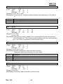
GS * x y d1...d (x X y X 8)
[Name] To define the download bit image
[Type]
ASCII
GS
*
x
y
d1...d (x X y X 8)
HEX
1D
2A
x
y
d1...d (x X y X 8)
DECIMAL 29
42
x
y
d1...d (x X y X 8)
[Range] 1 ≤ x ≤ 255
1 ≤ y ≤ 48 where, x x y ≤1536
0 ≤ d ≤ 255
[Description] Download bit image is used as clear dot by x and y.
- x: number of dots in horizontal direction
- y: number of dots in vertical direction (download bit image printing)
GS / m
[Name]
[Type]
To print download bit image
ASCII
GS
/
m
HEX
1D
2F
m
DECIMAL 29
47
m
[Range] 0 ≤ m ≤ 3, 48 ≤ m ≤ 51
[Description] The printing of download bit image is used as a clear mode by m.
Mode is selected by m as shown in the following table.
m
0,48
1,49
2,50
3,51
Rev. 1.05
Mode
Normal
Two times horizontal
magnification
Two times vertical
magnification
Overall two times
magnification
Vertical Dot Density
200 DPI
Horizontal Dot Density
200 DPI
200 DPI
100 DPI
100 DPI
200 DPI
100 DPI
100 DPI
- 37 -
SRP-150
GS :
[Name]
[Type]
To define beginning/end of macro
ASCII
GS
:
HEX
1D
3A
DECIMAL 29
58
[Description] To define beginning/end of macro
GS B n
[Name] Black and White switching printer mode on/off
[Type]
ASCII
GS
B
n
HEX
1D
42
n
DECIMAL 29
66
n
[Range] 0 ≤n ≤255
[Description] Black and White switching printer mode
- Black and White switching mode is OFF when LSB is 0
- Black and White switching mode is ON when LSB is 1
GS H n
[Name] To select the printing position of the HRI characters
[Type]
ASCII
ESC H
n
HEX
1D
48
n
DECIMAL 29
72
n
[Range] 0 ≤ n ≤ 3 , 48 ≤ n ≤51
[Description] To select the printing position of HRI characters when printing the bar code
Select the printing position using n as shown below
n
0,48
Printing position
No printing
1,49
Over the bard code
n
2,50
3,51
Printing position
Under the bar code
Both over and under
the bar code
- HRI (Human Readable interpretation)
[Default value] n = 0
GS I n
[Name]
[Type]
To send the printer ID
ASCII
ESC I
n
HEX
1D
49
n
DECIMAL 29
73
n
[Range] 1 ≤ n ≤ 3 , 49 ≤ n ≤ 51
[Description] To send the printer ID using n as shown below
n
Printer ID
1,49
Printer Model ID
2,50
3,51
Type ID
ROM Version ID
Rev. 1.05
Specifications
SRP-150P / SRP150U /
SRP-150S
Depends on ROM version
- 38 -
ID (HEXaDECIMAL)
30
02
10
SRP-150
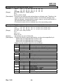
GS L nL nH
[Name] To set the left margin
[Type]
ASCII
GS
L
nL
nH
HEX
1D
4C
nL
nH
DECIMAL 29
76
nL
nH
[Range] 0 ≤ nL ≤ 255
0 ≤ nH ≤ 255
[Description] Left margin is determined by nL and nH.
Left margin is set to [(nL + nH X 256) X (horizontal motion unit6)] inches
Printable area
Left Margin
Printing area width
① GS V m
② GS V m n
[Name] To Select cut mode and cut paper
[Type]
① ASCII
GS
V
m
HEX
1D
56
m
DECIMAL 29
86
m
② ASCII
GS
V
m
n
HEX
1D
56
m
n
DECIMAL 29
86
m
n
[Range] ① m = 1, 49
② m = 66, 0 ≤ n ≤ 255
[Description] Selects a mode for cutting paper and executes paper cutting.
The value of m selects the mode as follows.
m
0, 1, 49
66
Print Mode
Partial cut (one point center uncut)
Feeds paper (cutting position + [n x )vertical motion unit)]),
And cuts the paper partially (one point center uncut).
GS W nL nH
[Name] To set the printing area
[Type]
ASCII
GS
W
nL
nH
HEX
1D
57
nL
nH
DECIMAL 29
87
nL
nH
[Range] 0 ≤ nL ≤ 255 , 0 ≤ nH ≤ 255
[Description] Printing area is accurately set by nL and nH.
Printing area is set to [(nL + 256 x nH) x horizontal motion unit] inches.
Printable area
Left Margin
Rev. 1.05
Printing area width
- 39 -
SRP-150
GS ^ r t m
[Name] To run the macro
[Type]
ASCII
GS
^
r
t
m
HEX
1D
5E
r
t
m
DECIMAL 29
94
r
t
m
[Range] 0 ≤ r ≤ 255 , 0 ≤ t ≤ 255 , 0 ≤ m ≤ 1
[Description] To run the macro
- r: Repetition frequency of macro execution.
- t: Delay time for executing all macros is t X 100 msec.
- m: Macro execution mode
LSB of m = 0
Macros will be executed r times continuously with a delay time of t.
LSB of m = 1
After waiting for the delay time t, paper out LED indicator blinks, and the
printer is in standby until the feed button is pressed. One the button is
depressed, the printer executes the macro once. And this operation is
repeated r times.
GS f n
[Name]
[Type]
To select the font of HRI (Human Readable interpretation) characters
ASCII
GS
f
n
HEX
1D
66
n
DECIMAL 29
102
n
[Range] n = 0, 48
[Description] To select the font of HRI characters used for barcode printing
Chinese version is not supported.
Select the font as in the table shown below.
N
0,48
Font
Font A (12 * 24)
GS h n
[Name]
[Type]
To set the height of the barcode
ASCII
GS
h
n
HEX
1D
68
n
DECIMAL 29
104
n
[Range] 1 ≤ n ≤ 255
[Description] To set the height of the barcode
n is number of dots in vertical direction.
[Default value] n = 162
Rev. 1.05
- 40 -
SRP-150
① GS k m d1...dk NUL ② GS k m n d1...dn
[Name] To printer barcode
[Type] ① ASCII
GS
k
m
d1...dk
NUL
HEX
1D
6B
m
d1...dk
00
DECIMAL
29
107
m
d1...dk
0
② ASCII
GS
k
m
n
d1...dn
HEX
1D
6B
m
n
d1...dn
DECIMAL
29
107
m
n
d1...dn
[Range] ① 0 ≤ m ≤ 6
(Values for k and d are determined by the barcode system.)
② 65 ≤ m ≤ 73 (Values for n and d are determined by the barcode system.)
[Description] Select the bar code system and print the barcode.
Barcode System
UPC-A
Number of Characters
11≤k≤12
JAN 13(EAN)
JAN8(EAN)
12≤k≤13
7≤k≤8
4
CODE39
1≤k
5
ITF
1≤k (even number)
6
CODABAR
1≤k
m
0
1
2
3
①
M
65
66
67
68
②
Barcode System
Number of Characters
UPC-A
11≤n≤12
JAN13(EAN)
JAN8(EAN)
12≤n≤13
7≤n≤8
69
CODE39
1≤n≤255
70
ITF
1≤n≤255 (even number)
71
CODABAR
1≤n≤255
72
73
CODE93
CODE128
1≤n≤255
2≤n≤255
Remarks
48≤d≤57
48≤d≤57
48≤d≤57
48≤d≤57,65≤d≤90,32,
36,37,43,45,46,47
48≤d≤57
48≤d≤57,65≤d1≤68,
36,43,45,46,47,58
Remarks
48≤d≤57
48≤d≤57
48≤d≤57
48≤d≤57,65≤d≤90,32,
36,37,43,45,46,47
48≤d≤57
48≤d≤57,65≤d1≤68
36,43,45,47,58
0≤d≤127
0≤d≤127
[When using CODE93 (m=72)]
- The printer will print the beginning of the HRI string with HRI character (□).
- The printer will print the end of the HRI string with the HRI character (□).
- The printer will print the control characters with HRI character
(■ + an alphabetic character).
Rev. 1.05
- 41 -
SRP-150
Control character
ASCII
HEX DECIMAL
NUL
00
0
SOH
01
1
STX
02
2
ETX
03
3
EOT
04
4
ENQ
05
5
ACK
06
6
BEL
07
7
BS
08
8
HT
09
9
LF
0A
10
VT
0B
11
FF
0C
12
CR
0D
13
SO
0E
14
SI
0F
15
HRI
character
■U
■A
■B
■C
■D
■E
■F
■G
■H
■I
■J
■K
■L
■M
■N
■O
Control character
ASCII
HEX DECIMAL
DLE
10
16
DC1
11
17
DC2
12
18
DC3
13
19
DC4
14
20
NAK
15
21
SYN
16
22
ETB
17
23
CAN
18
24
EM
19
25
SUB
1A
26
ESC
1B
27
FS
1C
28
GS
1D
29
RS
1E
30
US
1F
31
DEL
7F
127
HRI
character
■P
■Q
■R
■S
■T
■U
■V
■W
■X
■Y
■Z
■A
■B
■C
■D
■E
■T
<Example> Output GS k 72 7 67 111 100 101 13 57 51
[When using CODE128 (m=73)]
- When CODE128 is used for the printer, the details of the data transmission are as
follows.
① Code set character in front of the barcode string
One of CODE A, CODE B, or CODE C must be selected.
※ Description of the CODE128 bar code
CODE128 barcode is the combination of three types of code sets and 103
different barcode characters, and one barcode can represent 128 ASCII
codes and two digit numbers. Each code set can represent the following
characters.
* Code set A: ASCII character 00H to 5FH
* Code set B: ASCII character 20H to 7FH
* Code set C: Two digits number (100 numerals from 00 to 99)
Rev. 1.05
- 42 -
SRP-150
The following characters can be represented by the CODE128 barcode.
* SHIFT characters
In the code set A, the character right next to the SHIFT follows the process
of code set B. SHIFT character cannot be used in code set C.
* Code set selection character (CODE A, CODE B, CODE C).
This character converts the code set A, B, or C into following code set.
* Function character (FNC1, FNC2, FNC3, FNC4)
Using function characters depends on the application program.
Only FNC1 can be used in code set C.
② Special characters are defined as the combination of two characters, “{“, and one
character. ACSII character “{“ is defined as two consecutive transmissions of “{“.
Specific character
Transmit data
HEX
7B,53
7B,41
7B,42
7B,43
7B,31
7B,32
7B,33
7B,34
7B,7B
ASCII
{S
{A
{B
{C
{1
{2
{3
{4
{{
SHIFT
CODE A
CODE B
CODE C
FNC1
FNC2
FNC3
FNC4
“{“
DECIMAL
123,83
123,65
123,66
123,67
123,49
123,50
123,51
123,52
123,123
<Example> Example for printing “No. 123456”
In this example, code B is used for “No.” and the following numbers are printed
in code B.
GS k 73
10
123
66
78
111 46
123
67
12
34
56
* If there is no code selection character in front of the bar code data, the printer
will stop executing the command and the following data will be processed as
general data.
* If “{“ and the following character does not correspond to the certain special
character, the printer will stop executing the command, the following data will
be processed as general data.
* Code selection character and the SHIFT character are not printed as HRI
characters.
* FUNCTION characters will be shown as spaces in HRI characters.
* Control characters (<00>H to <1F>H and <7F>H) will be shown as spaces in
HRI characters.
<Miscellaneous> The empty space on the left and right sides of the barcode must
be secured.
(The empty space requirements are different depending on
barcode type.)
Rev. 1.05
- 43 -
SRP-150
GS v 0 m xL xH yL yH dl…dk
[Name] To print raster bit image
[Type]
ASCII
GS
v
0
m xL xH
yL yH
HEX
1D
76
30 m xL xH
yL yH
DECIMAL 29
118
48 m xL xH
yL yH
[Range] 0 ≤ m ≤ 3 , 48 ≤ m ( 51
0 ≤ xL ≤ 255 , 0 ≤ xH ≤ 255 , 0 ≤ yL ≤ 255
0 ( d ( 255
k = (xL+xHx256) x (yL+yHx256) (k=0)
[Description] To select the raster bit-image mode
The value of m for selecting each mode is as follows.
Mode
Normal
Double-width
Double-height
Quadruple
m
0,48
1,49
2,50
3,51
Vertical dot density
200dpi
200dpi
100dpi
100dpi
dl…dk
dl…dk
dl…dk
Horizontal dot density
200dpi
100dpi
200dpi
100dpi
- xL and xH are for selecting the number of data bit (xL + xH x 256) in
horizontal direction of the image.
- yL and yH are for selecting the number of data bit (yL + yH x 256) in
vertical direction of the image.
GS w n
[Name] To set the barcode width
[Type]
ASCII
GS
w
n
HEX
1D
77
n
DECIMAL 29
119
n
[Range] 2 ≤ n ≤ 6
[Description] To set the width of the barcode
Bi-level Bar Code
n
Thin element width
Thick element width
(mm)
(mm)
2
0.250
0.250
0.625
3
0.375
0.375
1.000
4
0.500
0.500
1.250
5
0.625
0.625
1.625
6
0.750
0.750
2.000
- Multilevel barcode: UPC-A, UPC-E, JAN13, CODE93, CODE128
- Bi-level barcode: CODE39, ITF, CODABAR
[Default value] n = 3
Module width (mm) for
Multi-level Bar Code
Rev. 1.05
- 44 -
SRP-150
☎ BIXOLON Co., Ltd.
● Website http://www.bixolon.com
● South Korea Headquarte
(Address) 7th~8th FL, Miraeasset Venture Tower, 685, Sampyeong-dong,
Bundang-gu, Seongnam-si, Gyeonggi-do, 463-400, Korea
(Tel)
+82-31-218-5500
● China Factory(Dongguan China)
(Address) (CA3)#11 Luyi 2 Road, Tangxia Town, Dongguan City, Guangdong
Province,P.R.China
(Tel)
+86 769 8262 0704~07
● American Office
(Address) BIXOLON America Inc., 3171 Fujita St, Torrance, CA 90505
(Tel)
+1-858 764 4580
● European Office
(Address) BIXOLON Europe GmbH, Tiefenbroicher Weg 35 40472 Düsseldorf
(Tel)
+49 (0)211 68 78 54 0
Rev. 1.05
- 45 -