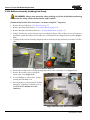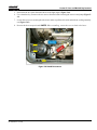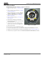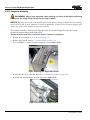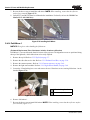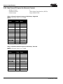
1
CP2210 Service Manual 020-100556-04 CP2210 Service Manual 020-100556-04 NOTICES COPYRIGHT AND TRADEMARKS © 2011 - 2012 Christie Digital Systems USA, Inc. All rights reserved. All brand names and product names are trademarks, registered trademarks or trade names of their respective holders. REGULATORY The product has been tested and found to comply with the limits for a Class A digital device, pursuant to Part 15 of the FCC Rules. These limits are designed to provide reasonable protection against harmful interference when the product is operated in a commercial environment. The product generates, uses, and can radiate radio frequency energy and, if not installed and used in accordance with the instruction manual, may cause harmful interference to radio communications. Operation of the product in a residential area is likely to cause harmful interference in which case the user will be required to correct the interference at the user’s own expense. This Class A digital apparatus complies with Canadian ICES-003. Cet appareil numérique de la classe A est conforme à la norme NMB-003 du Canada. 이 기기는 업무용 (A 급 ) 으로 전자파적합등록을 한 기기이오니 판매자 또는 사용자는 이점을 주의하시기 바라며 , 가정 외의 지역에서 사용하는 것을 목적으로 합니다 . GENERAL Every effort has been made to ensure accuracy, however in some cases changes in the products or availability could occur which may not be reflected in this document. Christie reserves the right to make changes to specifications at any time without notice. Performance specifications are typical, but may vary depending on conditions beyond Christie's control such as maintenance of the product in proper working conditions. Performance specifications are based on information available at the time of printing. Christie makes no warranty of any kind with regard to this material, including, but not limited to, implied warranties of fitness for a particular purpose. Christie will not be liable for errors contained herein or for incidental or consequential damages in connection with the performance or use of this material. The product is designed and manufactured with high-quality materials and components that can be recycled and reused. This symbol means that electrical and electronic equipment, at their end-of-life, should be disposed of separately from regular waste. Please dispose of the product appropriately and according to local regulations. In the European Union, there are separate collection systems for used electrical and electronic products. Please help us to conserve the environment we live in! Canadian manufacturing facility is ISO 9001 and 14001 certified. GENERAL WARRANTY STATEMENTS For complete information about Christie’s limited warranty, please contact your Christie dealer. In addition to the other limitations that may be specified in Christie’s limited warranty, the warranty does not cover: a. Damage occurring during shipment, in either direction. b. Projector lamps (See Christie’s separate lamp program policy). c. Damage caused by use of a projector lamp beyond the recommended lamp life, or use of a lamp supplied by a supplier other than Christie. d. Problems caused by combination of the product with non-Christie equipment, such as distribution systems, cameras, video tape recorders, etc., or use of the product with any non-Christie interface device. e. Damage caused by misuse, improper power source, accident, fire, flood, lightening, earthquake or other natural disaster. f. Damage caused by improper installation/alignment, or by product modification, if by other than a Christie authorized repair service provider. g. For LCD projectors, the warranty period specified applies only where the LCD projector is in “normal use.” “Normal use” means the LCD projector is not used more than 8 hours a day, 5 days a week. For any LCD projector where “normal use” is exceeded, warranty coverage under this warranty terminates after 6000 hours of operation. h. Failure due to normal wear and tear. PREVENTATIVE MAINTENANCE Preventative maintenance is an important part of the continued and proper operation of your product. Please see the Maintenance section for specific maintenance items as they relate to your product. Failure to perform maintenance as required, and in accordance with the maintenance schedule specified by Christie, will void the warranty. Table of Contents 1: Introduction 1.1 Labels and Marking .....................................................................................................................1-1 1.2 Projector Skins.............................................................................................................................1-1 Rear Access Door .................................................................................................................1-1 Cardcage Panel .....................................................................................................................1-2 1.2.1 Adjustable Feet ....................................................................................................................1-2 1.3 Module Overview ........................................................................................................................1-2 1.3.1 Optical and Electrical Systems ............................................................................................1-2 Light Path and Optical Components .....................................................................................1-2 Lamp .....................................................................................................................................1-3 LampLOC™ Module ............................................................................................................1-4 Integrator ..............................................................................................................................1-4 Cold Mirror Assembly ..........................................................................................................1-4 Contrast Aperture .................................................................................................................1-4 Fold Mirrors 1 and 2 .............................................................................................................1-4 Total Internal Reflection Prism (TIR) ..................................................................................1-4 Light Engine/DMD Assembly ..............................................................................................1-4 1.3.2 Shutter, Lens Mount, ILS and Projection Lens ...................................................................1-5 Shutter Assembly ..................................................................................................................1-5 Lens Mount ...........................................................................................................................1-5 Projection Lens .....................................................................................................................1-5 Intelligent Lens System (ILS) ...............................................................................................1-5 1.3.3 Power Modules ....................................................................................................................1-6 Low Voltage Power Supply (LVPS) ....................................................................................1-6 Standby Power Supply ..........................................................................................................1-6 Lamp Power Supply (LPS) ...................................................................................................1-6 Interlocks ..............................................................................................................................1-6 1.3.4 Electrical System & Components ........................................................................................1-7 Input Processing ...................................................................................................................1-7 1.3.5 Projector Cooling.................................................................................................................1-7 Fan Cooling ..........................................................................................................................1-8 Liquid Cooling ......................................................................................................................1-8 1.3.6 Power ...................................................................................................................................1-8 2: Service Guidelines 2.1 Technical Support........................................................................................................................2-1 2.2 Security Roles..............................................................................................................................2-1 2.3 Safety Precautions and Warnings ................................................................................................2-1 2.3.1 UV Light ..............................................................................................................................2-1 2.3.2 High Voltages ......................................................................................................................2-2 2.3.3 High Temperature ................................................................................................................2-2 2.4 Lamp Replacement ......................................................................................................................2-2 2.4.1 Lamp Serial Number............................................................................................................2-3 2.4.2 Resetting Lamp Position (LampLOC™) .............................................................................2-3 2.4.3 Setting Lamp Rotation .........................................................................................................2-3 CP2210 Service Manual 020-100556-04 Rev. 1 (01-2012) i Table of Contents 2.5 Cooling.........................................................................................................................................2-3 2.5.1 Ventilation............................................................................................................................2-3 2.5.2 Air Filter (P/N: 003-002311-01) ..........................................................................................2-4 2.5.3 Liquid Cooler (P/N: 003-001837-02) ..................................................................................2-4 2.6 Power Supplies ............................................................................................................................2-4 2.7 Power Cord ..................................................................................................................................2-4 2.8 General Service Guidelines..........................................................................................................2-5 2.8.1 Servicing ..............................................................................................................................2-5 2.8.2 Lead Dress............................................................................................................................2-5 2.8.3 Maintain Ground/Earth Connections ...................................................................................2-5 2.8.4 Ordering Parts ......................................................................................................................2-5 2.9 Replacing Modules ......................................................................................................................2-6 2.9.1 Repair Cautions....................................................................................................................2-6 2.10 Cleaning .....................................................................................................................................2-6 3: Service Setup 3.1 Alignment Procedures..................................................................................................................3-1 3.2 Fold Mirror Alignment ................................................................................................................3-2 3.3 Integrator Alignment....................................................................................................................3-3 3.4 Yellow Notch Filter Adjustment..................................................................................................3-4 3.5 Adjusting Lamp Position (LampLOC™) ....................................................................................3-4 3.5.1 Automatically Adjusting the Lamp Position Using LampLOC™.......................................3-5 3.5.2 Manually Adjusting the Lamp Position ...............................................................................3-6 3.5.3 DMD Convergence ..............................................................................................................3-7 3.6 Performing Marriage....................................................................................................................3-8 3.7 Upgrading Main Software............................................................................................................3-10 3.7.1 Steps to Install an Upgrade Package ....................................................................................3-10 3.7.2 Upgrade: File Selection Window .........................................................................................3-11 3.7.3 Upgrade: Package Details Window .....................................................................................3-12 3.7.4 Upgrade: Upgrade Progress Window ..................................................................................3-13 3.8 Hardware Change.........................................................................................................................3-14 4: Troubleshooting 4.1 Overview......................................................................................................................................4-1 4.2 Troubleshooting ...........................................................................................................................4-2 4.2.1 Symptom: Projector will not turn on to full power mode from standby..............................4-2 4.2.2 Symptom: Lamp will not ignite ...........................................................................................4-2 4.2.3 Symptom: Lamp ignites but won’t stay on ..........................................................................4-2 4.2.4 Symptom: LampLOC™ not working ..................................................................................4-3 4.2.5 Symptom: LiteLOC™ not working .....................................................................................4-3 4.2.6 Symptom: DMD over-temperature warning ........................................................................4-3 4.2.7 No Image, Just Pink Snow ...................................................................................................4-3 4.2.8 Symptom: No image displays, just black screen (or green screen in 3D) ...........................4-4 ii CP2210 Service Manual 020-100556-04 Rev. 1 (01-2012) Table of Contents 5: Parts and Module Replacement 5.1 Ordering Parts..............................................................................................................................5-1 5.2 Index of Parts and Modules .........................................................................................................5-1 5.3 Safety Warnings and Guidelines .................................................................................................5-4 5.4 Replacement Procedures..............................................................................................................5-4 5.4.1 Servicing Guidelines............................................................................................................5-4 5.4.2 Tools Required.....................................................................................................................5-4 5.5 Removing Projector Covers.........................................................................................................5-5 5.5.1 Air Filter Cover....................................................................................................................5-5 5.5.2 Intake Air Filter ...................................................................................................................5-5 5.5.3 Front Face Skin...................................................................................................................5-5 5.5.4 Touch Panel Controller (TPC).............................................................................................5-6 5.5.5 Top Lid ................................................................................................................................5-7 5.5.6 High Security Lid.................................................................................................................5-7 5.5.7 Cardcage Panel Skin ............................................................................................................5-8 5.5.8 Rear Access Door Skin ........................................................................................................5-8 5.5.9 Side Skin Service Door........................................................................................................5-9 5.5.10 Lamp Door........................................................................................................................5-9 5.5.11 Exhaust Panel Skin ...........................................................................................................5-10 5.5.12 Safety Shield .....................................................................................................................5-10 5.5.13 Intake Duct........................................................................................................................5-11 5.5.14 Radiator Filter ...................................................................................................................5-12 5.5.15 Lamp Replacement ...........................................................................................................5-13 Installing a New Lamp .........................................................................................................5-14 5.5.16 Lens...................................................................................................................................5-15 5.5.17 Lens Flags .........................................................................................................................5-15 5.5.18 Lamp Blower Assembly ...................................................................................................5-16 5.5.19 Standby Power Supply......................................................................................................5-17 5.5.20 Projector Feet....................................................................................................................5-18 5.5.21 Lamp Door Interlock ........................................................................................................5-18 5.5.22 Lamp Power Supply (LPS) ...............................................................................................5-19 5.5.23 Lamp Adjust Assembly ....................................................................................................5-22 5.5.24 Reflector Assembly (Including Heat Dump) ....................................................................5-24 5.5.25 UV Filter ...........................................................................................................................5-25 5.5.26 Low Voltage Power Supply (LVPS) ................................................................................5-26 5.5.27 Liquid Cooling Assembly.................................................................................................5-27 5.5.28 Light Dump.......................................................................................................................5-29 5.5.29 Light Engine .....................................................................................................................5-30 5.5.30 Shutter Assembly..............................................................................................................5-31 5.5.31 Primary Lens Mount .........................................................................................................5-32 5.5.32 Lamp Power Supply (LPS) - Fans 1 and 2 .......................................................................5-33 5.5.33 AC Line Filters .................................................................................................................5-33 110V AC Line Filter .............................................................................................................5-34 220V AC Line Filter .............................................................................................................5-34 A/C Selector Switch .............................................................................................................5-35 CP2210 Service Manual 020-100556-04 Rev. 1 (01-2012) iii Table of Contents 5.6 Cardcage and LVPS Compartment..............................................................................................5-35 5.6.1 Cardcage Module .................................................................................................................5-35 5.6.2 Internal Motor Control Board (IMCB) ................................................................................5-38 5.6.3 Environmental Board (EVB) ...............................................................................................5-39 5.6.4 Light Engine Quick Disconnect (LEQD).............................................................................5-39 5.6.5 Projector Intelligence Board (PIB) ......................................................................................5-40 5.6.6 Integrated Cinema Processor (ICP)......................................................................................5-41 5.6.7 Link Decrypter Card ............................................................................................................5-41 5.6.8 Backplane.............................................................................................................................5-42 5.6.9 Fans ......................................................................................................................................5-43 Light Engine Intake Fan- Fan 8 ............................................................................................5-43 Fan Pack (Intake - Fans 5, 6, 7 and 8) ..................................................................................5-44 5.6.10 Integrator Assembly ..........................................................................................................5-45 5.6.11 Contrast Aperture ..............................................................................................................5-47 5.6.12 Light Sensor Module.........................................................................................................5-47 5.6.13 Cold Mirror .......................................................................................................................5-48 5.6.14 Fold Mirror 1.....................................................................................................................5-49 5.6.15 Fold Mirror 2.....................................................................................................................5-50 5.6.16 Yellow Notch Filter (YNF)...............................................................................................5-51 5.6.17 Illumination Optic System (IOS) ......................................................................................5-51 5.6.18 Cooling Water Blocks and Hoses .....................................................................................5-52 6: Interconnections 7: Serial API 8: Specifications 8.1 Display .........................................................................................................................................8-1 8.1.1 Panel Resolution and Refresh Rate ......................................................................................8-1 8.1.2 Achievable Brightness (Measured at Screen Center) ..........................................................8-1 8.1.3 Achievable Contrast Ratio ...................................................................................................8-1 8.1.4 Color and Gray Scale ...........................................................................................................8-1 8.1.5 White Point ..........................................................................................................................8-1 8.1.6 Gamma .................................................................................................................................8-1 8.2 Source Signal Compatibility ........................................................................................................8-2 8.2.1 Cinema Inputs ......................................................................................................................8-2 8.2.2 Non-Cinema DVI Inputs (for Alternate Content) ................................................................8-4 8.3 Control Signal Compatibility.......................................................................................................8-5 8.3.1 Ethernet Port ........................................................................................................................8-5 8.3.2 RS232-PIB ...........................................................................................................................8-5 8.3.3 RS232-ICP ...........................................................................................................................8-5 8.3.4 GPIO Port.............................................................................................................................8-5 8.3.5 Simple Contact Closure Interface (SCCI) Port ....................................................................8-6 8.3.6 3D Port .................................................................................................................................8-6 8.3.7 MALM (located on Auxiliary Input Panel) .........................................................................8-6 8.4 Touch Panel Controller ................................................................................................................8-6 iv CP2210 Service Manual 020-100556-04 Rev. 1 (01-2012) Table of Contents 8.4.1 TPC-660E ............................................................................................................................8-6 8.4.2 TPC-650H............................................................................................................................8-7 8.5 Power Requirements....................................................................................................................8-7 8.5.1 AC Input ..............................................................................................................................8-7 8.5.2 UPS AC Input ......................................................................................................................8-7 8.6 Lamp ............................................................................................................................................8-7 8.7 Physical Specifications ................................................................................................................8-8 8.8 Regulatory ...................................................................................................................................8-8 8.8.1 Safety ...................................................................................................................................8-8 8.8.2 Electro-Magnetic Compatibility ..........................................................................................8-8 Emissions ..............................................................................................................................8-8 Immunity ..............................................................................................................................8-8 Environmental ......................................................................................................................8-8 8.9 Environment ................................................................................................................................8-10 8.9.1 Operating Environment........................................................................................................8-10 8.9.2 Non-Operating Environment ...............................................................................................8-10 8.10 Accessories ................................................................................................................................8-10 8.10.1 Standard (sold with product).............................................................................................8-10 8.10.2 Accessories (sold separately)............................................................................................8-10 A: Shutter Override A.1 Shutter Manual Override ............................................................................................................A-1 B: Overfill B.1 Overfill ........................................................................................................................................B-1 B.1.1 Overfilled Image .................................................................................................................B-1 B.1.2 Converting Centimeters to Pixels........................................................................................B-2 C: Exploded Views CP2210 Service Manual 020-100556-04 Rev. 1 (01-2012) v 1 Introduction To prevent physical injury or equipment damage, it is important to study Section 2 Service Guidelines in its entirety before performing any service procedure. This manual provides technical information for assisting Christie authorized service technicians in the servicing and repair of CP2210 projector models. Disclaimer: Every effort has been made to ensure the information in this document is accurate and reliable. However, due to constant research, the information in this document is subject to change without notice. Christie Digital Systems assumes no responsibility for omissions or inaccuracies. Updates to this document are published regularly, as required. Please contact Christie Digital Systems for availability. 1.1 Labels and Marking Observe and follow any warnings and instructions marked on the projector. Danger symbols indicate a hazardous situation which, if not avoided, will result in death or serious injury. This signal word is to be limited to the most extreme situations. Warning symbols indicate a hazardous situation which, if not avoided, could result in death or serious injury. Caution symbols indicate a hazardous situation which, if not avoided, could result in minor or moderate injury. NOTICE: Addresses practices not related to personal injury. 1.2 Projector Skins UV HAZARD! When servicing the projector with the top lid removed anyone within the immediate vicinity must wear safety glasses with side shields and Christie approved protective safety clothing (P/N: 598900-095). Never operate the projector or the fans without all the covers installed. Durable covers are used to protect the components within the projector. Several removable covers (also called skins) allow access to serviceable components without having to completely disassemble the projector. For details, refer to Appendix C: Exploded Views. Rear Access Door Located at the back of the projector is the rear access door, which includes a low security access lock/ key and the Touch Pad Controller (TPC). Mounted to the inside of the door is the lamp blower assembly and the lamp changeover tool required to tighten/loosen the cathode clamp. CP2210 Service Manual 020-100556-04 Rev. 1 (01-2012) 1-1 Section 1: Introduction Cardcage Panel Located on the right-side of the projector is the cardcage panel, which includes the Integrated Cinema Processor (ICP) and Projector Intelligence Board (PIB) interface panels. From this location all input sources can be connected. 1.2.1 Adjustable Feet The four adjustable feet on the bottom of the projector allow up to 15° degrees of tilt to aid in leveling the projector. Image keystone and other geometric image problems can occur if the projector is not sitting level. For more information, refer to 5.5.20 Projector Feet, on page 5-18. NOTE: When installing the CP2210 on the optional rack stand (P/N:108-282101-xx or P/N:108-272101-xx) the foot lock brackets (P/N:119-100101-xx) must be installed for safety purposes. 1.3 Module Overview The following section provides an in-depth look at the projector's components, their main functions and how they interface with other components. Knowing your projector and how it works will help during troubleshooting. 1.3.1 Optical and Electrical Systems The two largest and most complex systems in the projector are the optical and electrical systems. A basic understanding of each of these systems and the relationship between their components can improve troubleshooting efforts. Light Path and Optical Components The majority of the optical components reside in the front portion of the projector, with the reflector/lamp, UV filter and cold mirror physically separated from the optics by a thermal firewall. This wall segregates those components generating the greatest heat and EMI emissions. The integrator mount is located through the firewall partition. A precisely machined case base plate ensures proper alignment between the lamp and the Illumination Optics System (IOS). Alignment between other optical components is also critical, requiring tight tolerances in their case IOS holder, as well as thermal stability throughout the front compartment of the projector. 1-2 CP2210 Service Manual 020-100556-04 Rev. 1 (01-2012) Section 1: Introduction Figure 1-1 Optical Light Path 1 Reflector/Lamp 8 Yellow Notch Filter/Lens 2 2 UV Filter 9 Fold Mirror 2 3 Cold Mirror 10 Vignetting Aperture 4 Integrator Rod 11 Lens 5 5 Lens 1 12 Light Engine 6 Fold Mirror 1 13 Lens 7 Contrast Aperture Lamp-to-Integrator: Bright light is generated by the internal lamp (1.4kW, 1.8kW or 2.0kW). Dual front/rear glass reflectors direct light from the lamp through a UV filter to the integrator where its internal silica rod distributes the slightly irregular intensity of the light beam equally across a rectangular field, then passes this light to the first lens in the IOS. Integrator-to-IOS: At the entrance of the IOS, light from the integrator passes through the first lens and vignetting aperture. This aperture controls the f/ in the corners of the image and directs the light on to the adjacent fold mirror 1 and folds the remaining light down 45° through the f/# aperture. This aperture controls the f-number of the light in the system and directs the appropriate amount of light into a series of three more lenses. Light from the lenses then strikes the yellow notch filter at the bottom of the IOS, where the light beam folds once more, angling 45° up through the final lens and into the entrance of the prism. ISO-to-Prism and Light Engine Assembly: Upon entering the Total Internal Reflection (TIR) prism, light is internally reflected towards the color prism and then onto the Digital Micromirror Devices (DMDs). In this initial pass of light - when light enters the TIR prism via the IOS - the angle of incidence ensures all light is reflected and sent to the color splitting prism. Dichroic reflectors in the color splitting prism split incoming white light into its red, green and blue color components. Each light component then illuminates the corresponding red, green or blue rectangular DMD panel in the light engine, where thousands of mirrors (for “pixels”) continuously tilt either ON or OFF in response to incoming source signals. Whether in the ON or OFF position light striking the mirrors reflects back through the color prism, but at different angles depending on the position. However, when the mirrors are in the OFF position light is not collected by the projection lens. Light striking the ON mirrors of any DMD reflects back to the color splitting prism, where all three color components arriving from each DMD are recombined. The recombined light then returns to the first prism and—due to its new angle of incidence— is collected by the projection lens and imaged on the screen. Precise mechanical alignment of the three DMD panels ensures their respective pixels converge with one another and are continuously superimposed onscreen in sharp full-color images. Dowel pins/holes on the IOS ensure the light engine assembly (which secures to the IOS) is accurately aligned to both the IOS and lens when installed. Adjustment of the lens determines final focus, zoom and offsets for the image. NOTE: Every pixel of a 2048x1080 input signal maps to its own mirror on the DMDs. If the input signal resolution is lower, projector software can resize the image to use more pixels. Without resizing, only the central mirrors defining this smaller area will be ON — the border of remaining mirrors will be OFF. Lamp Only service technicians trained specifically by Christie on lamp replacement and lamp safety may handle the lamp. High-pressure lamp may explode if improperly handled. Always wear Christie approved protective safety clothing (P/N:598900-095) whenever the internal lamp door is open or while handling the lamp. CP2210 Service Manual 020-100556-04 Rev. 1 (01-2012) 1-3 Section 1: Introduction The lamp is the primary light source for the projector. The lamp can be replaced by a Christie authorized service technician through a rear access door, without having to remove the reflector assembly. When necessary, the lamp can be rotated. Lamp position can be adjusted relative to the reflector with a motorized three-axis LampLOC™ mechanism. For lamp replacement instructions, refer to 5.5.15 Lamp Replacement, on page 5-13. LampLOC™ Module The electro-mechanical LampLOC™ module (a.k.a. lamp adjuster) adjusts the lamp along three axes to optimize the lamp position relative to the reflector. With the lamp “aimed” properly, the greatest amount of light will be collected, by the reflectors and used in the optical system. All adjustments are motorized using three linear actuation driven stepper motors on the LampLOC™ module, controlled by the nearby Intelligent Motor Control Board (IMCB). Feedback from the light sensor module indicates where the light output is maximized, terminating the lamp movement. In case of an electronics failure, the motors can be controlled manually with thumbwheels (service technician required, as the rear panel of the projection head must be removed). The physical range of adjustment along any axis is approximately ±4mm (0.16”). Integrator The optical integrator is a precisely aligned solid fused silica pipe. Output from the lamp enters the first end of the optical integrator as an intense round beam of light that is brightest in the center. As the light beam travels through the integrator all wavelengths are completely reflected multiple times within the integrator, exiting as a "homogenized" (uniformly bright) 1.896 rectangle. The integrator also mixes the various colors of the lamp regions and smooths any flicker caused by the arc instability of the lamp. Light exiting the integrator rod enters the optical head where it undergoes further treatment before it reaches the single DMD panel at the opposite end of the light path. Cold Mirror Assembly The cold mirror is mounted at an angle to the integrator assembly. It is responsible for removing heat in the form of non-useful IR and UV from the light beam before it is passed onto the prism assembly. Contrast Aperture Located between the two fold mirrors of the illumination system is a fixed contrast aperture, which controls the diameter of the light beam passing through the system, consequently affecting brightness and contrast. Fold Mirrors 1 and 2 Fold mirror 1 is positioned between lenses one and two. The second fold mirror is positioned between lenses four and five. Both mirrors are used to fold the light to direct it to the TIR prism in the light engine. Total Internal Reflection Prism (TIR) The TIR prism is responsible for redirecting the light from the relay system at the right angle of incidence to fully illuminate the DMD panel. This allows the modulated light from the DMD to come back through the prism and go straight through to the projection lens Light Engine/DMD Assembly The three DMDs in the projector are rectangular panels made up of tiny moveable mirrors (also called pixels). The number of pixels per DMD is determined by the resolution of the light engine. Each DMD is mounted with its own circuitry and includes liquid cooling blocks. Each panel receives and reflects one primary color of 1-4 CP2210 Service Manual 020-100556-04 Rev. 1 (01-2012) Section 1: Introduction light; red, green or blue. The three DMD assemblies are arranged in a precision mechanical structure, forming the final portion of the optical/DMD subsystem. NOTE: Like all other components of the optical assembly, the DMD panel is not serviced separately. When each color of light strikes the corresponding red, green or blue DMD panel, thousands of individual pixels function as optical switches that can be either ON or OFF. Each pixel tilts to either an ON or OFF position in response to the incoming signal processed by the projector. This position determines whether or not the light striking the panel is used or discarded. If any pixel on a DMD is OFF then the light striking that pixel is immediately directed to an absorbing plate so that it cannot inadvertently reflect back into the projection lens and reduce contrast. Light striking the ON pixels of any DMD reflects back to the color splitting prism, where the three color components arriving from the DMDs are recombined and sent on for display. 1.3.2 Shutter, Lens Mount, ILS and Projection Lens Shutter Assembly The shutter, commonly called a douser in cinema applications, is a separate assembly made up of a small blade with its own servo motor. It is located between the light engine and the projection lens. When the Douser Closed button is pressed from the Touch Panel Controller (TPC), the blade rotates into the light path, blocking it from entering the light engine. Lens Mount The motorized lens mount is mounted to the base of the projector and includes two servo motors for the remote control of horizontal and vertical offsets. The amount of travel is ±8mm in both horizontal and vertical directions. There is no manual override for the motorized drive. Linear motion is guided by precision rods and bushings. There is a three-point symmetrical boresight adjustment, which is lockable and can be adjusted without removing covers. The projection lenses are fitted with an interface plate, which mates with the lens mount. Magnets on the lens mount pull the lens onto the mount during insertion. Two hex screws are used to secure the lens to the mount. The lens is retained by a lens barrel clamping mechanism, which locks the lens in place with a clamping lever. Projection Lens NOTICE: Never apply power to the projector unless the primary lens is installed. A primary lens inserts into the lens mount and is secured with two hex screws, a simple locking lever and magnets. It is important to remember that a primary lens seals the projection head—if the lens is missing when power is supplied to the unit, unfiltered air will be drawn in through the lens opening and into the front area of the projection head, potentially depositing dust and dirt on components in the light engine and optics. The projection lens images the combined modulated light from the three DMDs and prisms for projection onto the screen. The various types of lenses enable you to use a throw ratio appropriate for your application. Refer to Section 8 Specifications for a list of available lenses and Section 5 Parts and Module Replacement for instructions on lens installation and removal. The attachment of the three-plate lens mount is offset by jack screws spaced far apart from one another to provide solid leverage and accurate adjustment of boresight. Good boresight ensures alignment of the primary lens to the light engine and prism. Refer to the CP2210 User Manual (P/N: 020-100410-xx) for the boresight adjustment procedure. The optional anamorphic lens (1.25x) can produce 2.39:1 “scope” images when used in combination with the primary lens. Intelligent Lens System (ILS) CP2210 Service Manual 020-100556-04 Rev. 1 (01-2012) 1-5 Section 1: Introduction The ILS has the ability to recall focus and zoom settings specific to each source input. Custom lens settings that you have chosen for any source will be quickly and accurately applied when you select a source that has already been calibrated. For details, refer to the CP2210 User Manual (P/N: 020-100410-xx). 1.3.3 Power Modules Low Voltage Power Supply (LVPS) The LVPS is a power regulating sub-system used to power small signal circuitry. The LVPS supplies +12VDC and +24VDC to the backplane when it is ON. The backplane then passes power on to the components connected to it. +12V is supplied to the AC relay module. +12V and +24V is supplied to the Environmental Board (EVB) and the Internal Motor Control Board (IMCB) to drive the fans and motors. Standby Power Supply Provides +24VDC to the Touch Panel Controller (TPC), backplane, EVB and IMCB. Lamp Power Supply (LPS) This power supply is non-serviceable. Never attempt to open or service this module - serious injury may result. A faulty supply must be replaced. The LPS is located on the right-side at the rear of the projector and is responsible for supplying the lamp with power for operation. Interlocks Eight interlocks detect when a critical component has failed. Safety Interlocks • Lamp Door: Detects if the lamp door is open and if the lamp compartment is over-temperature. • Fire Alarm: Detects if facilities fire alarm is activated. Software Interlocks • Temperature Sensor #1: Detects increased temperature at the blue DMD. • Temperature Sensor #2: Detects increased temperature at the green DMD. • Temperature Sensor #3: Detects increased temperature at the red DMD. • Temperature Sensor #4: Detects increased temperature at the cardcage. NOTE: This interlock does not turn the lamp OFF. • Temperature Sensor #5: Detects increased temperature at the filtered air intake. NOTE: This interlock does not turn the lamp OFF. • Temperature Sensor #6: Detects increased temperature at the lamp exhaust. The lamp door and fire alarm sensors are linked to a safety interlock circuit. If either of them indicates a malfunction, Lamp Power Supply (LPS) output is turned OFF and an error message is displayed on the TPC. The temperature sensors detect if there is an increase in temperature at one of the DMDs and the prism, as well as at the cardcage, filtered air intake and lamp exhaust. At this time, a warning message will display on the TPC. If the condition of the projector is ignored, another warning indicating shutdown is imminent will display. The cardcage and filtered air intake interlocks are the only two software interlocks that DO NOT turn 1-6 CP2210 Service Manual 020-100556-04 Rev. 1 (01-2012) Section 1: Introduction the lamp OFF. It is extremely important to pay attention to the warnings and status of the projector to prevent permanent damage. For complete details, refer to Section 6 Interconnections. 1.3.4 Electrical System & Components The overall electrical system includes subsystems for input processing, control, cooling and power. Input Processing Sources: Incoming source data determines the continuous ON/OFF states of the DMD pixels. The CP2210 accepts two SMPTE 292M digital video inputs intended for the DLP Cinema® inputs configured as dual-link for DCI compatibility. These serial digital signals are generated from a server or a decoder box (e.g., QuBit, Avica, EVS). Other “non-cinema” or “alternative” signal types connect to a DVI-D port. Sources connect to the input panel located on the right-side of the projector. For details about connecting sources, refer to the CP2210 User Manual (P/N: 020-100410-xx). Cardcage Electronics: The cardcage contains all main processing PCBs: the PIB, ICP, link decrypter, backplane and LEQD. Four fans are responsible for cooling the electronics by blowing air across them. Light Engine with Five-Element Prism: The light engine is the essence of the imagining system. All processing is done in the digital domain, controlling the position of the DMD mirrors as ON/OFF in response to the incoming signal. Contrast and brightness (black level) are preset for DLP Cinema® presentations and cannot be adjusted. Service access to the projector requires keyed entry-with the proper panels removed, and all convergence adjustment screws can be accessed from the top and operator's side. Color Calibration: As part of every installation, the projector's color processing is calibrated to achieve the required proprietary digital cinema color performance standards-called Target Color Gamut Data (TCGD). This calibration procedure takes into account the various environmental factors; such as type of port window, screen, ambient light, etc., and must be repeated if there is a change in any of these variables. Lamp Power Supply (LPS) Interface Signals: The 15-pin connector on the LPS end splits into three separate harnesses that go to the backplane, fire alarm interlock (hard-wired) and the lamp door interlock (hard-wired). This connector links the LPS controls to the rest of the projector. The LPS-to-backplane connection carries RS232 (serial) control signals for “lamp enable” and LPS output power adjustment, while allowing the projector to continuously monitor LPS operation. There are two hard-wired LPS interlocks, one for the lamp door and another for the fire alarm. The fire alarm interlock can be connected, if desired, to the theatre’s fire alarm system—this would then shut the lamp OFF in the event of a fire and is a safety requirement in certain countries. For sites in which the fourth interlock is not used, it is generally shorted to ground. The LPS communication/control cables each route into a single 15-pin connector. For details, refer to Section 6 Interconnections. 1.3.5 Projector Cooling The projector uses fans throughout to cope with the significant amount of heat generated by the lamp and other electrical components. These fans turn ON when the projector is powered ON and OFF only after the projector has cooled down - even after the power is turned OFF. Built-in fans run at all times to cool the Low Voltage Power Supply (LVPS). The lamp is cooled by two DC blower fans; one for the anode and another for the cathode. The lamp cooling air flows from right-to-left across the projector and is unfiltered. The light engine is cooled by filtered air entering the front of the projector. This air passes through a 90mm fan attached to the side of the light engine mount, passes over the light engine (cooling the prism, light dump and (3) DMD heatsinks), exits the light engine mount at the bottom left-side, and exhausts out of the side of the projector. The cardcage is cooled by filtered air entering the front of the projector. Four axial 90mm fans provide this airflow. The air cools the cardcage front to back; with the heated exhaust air flowing into the lamp compartment. CP2210 Service Manual 020-100556-04 Rev. 1 (01-2012) 1-7 Section 1: Introduction Fan Cooling Fan speed is controlled through temperature sensors, which measure inlet air temperature (ambient), lamp exhaust air temperature and light engine temperature. These sensors allow fan speed to be adjusted according to a calculated cooling demand determined by the sensors. The fan speed is adjusted using a Pulse-Width-Modulated (PWM) signal from the backplane. All fans are +12VDC fans. • Lamp (Fans 1 and 2): Two DC blower fans; one for the anode and the other for the cathode are used to cool the lamp. If necessary, a spare fan is available to cool the reflector. The unfiltered lamp cooling air flows from right-to-left across the projector. • Light Engine (Fan 8): The light engine is cooled by filtered air entering the front of the projector. This air passes through (2) 90mm fans attached to the side and (1) 90mm fan under the light engine mount, passes over the light engine from right-to-left (cooling the prism, light dump and the DMD heatsinks), exits the light engine mount at the bottom left side, and exhausts out of the side of the projector. If necessary, a spare fan is available to provide additional cooling to the light engine. • Cardcage (Fans 6, 7, 10 and 11): Two axial 90mm fans are used to filter air entering the front of the projector in order to cool the cardcage. The air cools the cardcage front to back; with the heated exhaust air flowing into the lamp compartment. Liquid Cooling The liquid cooling system is the primary method for cooling the light engine DMDs. This system consists of small water blocks screwed to the three DMD mounting studs and daisy chained together with UV-resistant Tygon flexible tubing. Both ends of the chain connect to two quick-release shutoff connectors, forming the cool “source” and warm “return” lines with the adjacent liquid cooler heat exchanger and pump. This liquid cooling loop circulates Christie approved coolant - JEFFCOOL E105. The level of fluid in the reservoir can only be seen if the projector top lid is opened. 1.3.6 Power DO NOT attempt operation if the AC supply is not within the voltage range specified on the license label on the back of the projector. Always turn the projector off before you unplug the AC power cord. Wait 15 minutes for the main exhaust fan to turn OFF and for the lamp to cool before you unplug the projector. Power remains available to the projector even after lamp shutdown (STANDBY mode) to enable on-line monitoring and software upgrades to be performed. The projector is powered by 200-240VAC power from the theater. The switching Lamp Power Supply (LPS) provides a well regulated DC current up to 85 amps with a maximum LPS power of 2.1kW. The power output from the LPS is controlled by the PCM, via a dedicated ‘RS232’ connection from the backplane to the LPS. A switch selectable secondary 100-240VAC inlet is provided, allowing the main electronics to be powered separately, via a universal 100-240VAC UPS. The main LPS is powered through the main 200-240VAC inlet. A discrete AC switch above the two inlets (Figure 1-2) allows the user to select whether the main electronics are powered from the main inlet - A only - (requiring only one power cord to supply the entire unit), or the secondary inlet supplied by the UPS - A+B -, via an additional power cord (not provided). 1-8 Figure 1-2 AC Receptacle CP2210 Service Manual 020-100556-04 Rev. 1 (01-2012) 2 Service Guidelines This section includes important safety and warning guidelines to ensure safe operation of the projector. 2.1 Technical Support If you have any questions or concerns regarding this product and require further information please contact Christie's technical support staff. Reference the company website www.christiedigital.com for product information. 2.2 Security Roles Only Christie authorized service technicians should perform field repair and service to the unit. Marriage must also only be performed by Christie authorized service technicians. Theater personnel may only perform diagnostic functions, such as running Interrogator. 2.3 Safety Precautions and Warnings Perform servicing ONLY after becoming thoroughly familiar with the following service guidelines. Noncompliance increases the risk of hazards and injury to the user. DO NOT modify any circuit. The CP2210 is internationally approved and is designed for safe and reliable operation. To ensure complete safety at all times for users, as well as service technicians, it is imperative that precautions be taken into consideration during servicing and that the original projector design remains intact. 2.3.1 UV Light UV HAZARD! Never look directly into the lens or into an open projector. The extreme light output could cause permanent eye damage. Wear ultraviolet-blocking eyewear with side-guards if servicing with the lamp ON. The projector lamp is an intense source of light and heat. One component of the lamp light is ultraviolet (UV) light, which can produce the same effect on the skin and eyes as sunlight. Avoid exposure to UV radiation by keeping the lamp fully enclosed when operating the projector, by remaining as far from it as possible and by wearing full protective gear approved for this projector before opening the lamp door. DO NOT operate the lamp without the lamp door in place. NOTES: 1) The American Conference of Governmental Industrial Hygienists (ACGIH) recommends occupational UV exposure for an 8-hour day to be less than 0.1 microwatts per square centimeters of effective UV radiation. An evaluation of your workplace is advised to ensure that employees are not exposed to cumulative radiation levels exceeding the government guidelines for your area. 2) Be aware that some medications are known to increase sensitivity to UV radiation. This projector must be operated in an environment that meets the operating range specifications, as listed in Section 8 Specifications. CP2210 Service Manual 020-100556-04 Rev. 1 (01-2012) 2-1 Section 2: Service Guidelines 2.3.2 High Voltages High voltages may be exposed—Qualified personnel only. Always power down and unplug the projector prior to disassembly. High voltages capable of causing DEATH are used in this projector. Before servicing, observe all precautions necessary for working on HIGH VOLTAGE equipment. 2.3.3 High Temperature Only Christie authorized service technicians trained specifically on lamp replacement and lamp safety may handle the lamp. A high-pressure lamp may explode if improperly handled. Always wear Christie approved protective safety clothing (P/N: 598900095) whenever the lamp door is open or while handling the lamp. Never attempt to access the lamp while it is running. Wait at least 15 minutes after turning the lamp OFF before powering down, disconnecting from AC and opening the lamp door. The projector lamp operates at very high temperatures and pressures. Failure to allow the bulb to sufficiently cool prior to handling could result in an explosion causing personal injury and/or property damage. After powering the lamp OFF, it is important to wait at least 15 minutes before disconnecting AC and opening the lamp door. This practice provides enough time for the internal lamp cooling fans to cool the bulb. Always cool the bulb completely before handling and always wear Christie-approved protective safety gear (P/N: 598900095) before opening the lamp door. 2.4 Lamp Replacement EXPLOSION HAZARD! Lamp replacement must be performed by Christie trained personnel only. Wear authorized protective clothing (P/N:59-8900-095) whenever the lamp door is opened and when handling the lamp. Never apply a twisting or bending force to the quartz lamp body. Use the correct wattage lamp supplied by Christie. Ensure those within the facility of the projector are also wearing protective safety clothing. Never attempt to remove the lamp when it is hot. The lamp is pressurized when hot and may explode, causing personal injury or death and/or property damage. Allow the lamp to cool completely. Never exceed the warranted lamp lifetime by more than 20%, as an old lamp becomes increasingly fragile and more prone to sudden failure or even explosion. To check how many hours have been logged on the current lamp, check the Advanced Setup: Lamp Power/LiteLOC Setup window from the TPC. Refer to 5.5.15 Lamp Replacement, on page 5-13. 2-2 CP2210 Service Manual 020-100556-04 Rev. 1 (01-2012) Section 2: Service Guidelines 2.4.1 Lamp Serial Number NOTE: Failure to enter a serial number when a new lamp is installed, will not trigger the lamp timer to reset to “0”, causing lamp hours to be inaccurate. The Lamp Limit that is set may also expire prematurely. Whenever a new lamp is installed, record its new serial number in the Advanced Setup: Lamp History window of the TPC, click the Add Lamp button and record lamp type, serial number, reason for change and number of hours logged on the lamp. If the lamp has not been previously used, enter 0. Click Save to enter the new data. 2.4.2 Resetting Lamp Position (LampLOC™) Always reset LampLOC™ when the projector is first installed and initially powered up, anytime the lamp is replaced or inspected, when a new LampLOC™ module is installed and whenever the projector is moved and leveled. Align a newly-installed lamp to ensure optimized lamp performance and peak brightness at the screen for the life of the lamp. The motors and sensors in the projector work together to precisely position the lamp for optimized performance. Once aligned, the LampLOC™ setting can be considered fairly stable for the life of the lamp. For more information, refer to the CP2210 User Manual (P/N: 020-100410-xx). 2.4.3 Setting Lamp Rotation When lamp rotation is required, it is important to follow the same safety precautions used when replacing a lamp. Rotating a lamp when it has reached half of its lifetime improves its performance and life expectancy. From the TPC Administrator Setup: Preferences window, enter a checkmark in the Lamp Rotation checkbox. This will trigger a message that half of the lamp’s limit (as set in Lamp Expiry) has been reached. By default Lamp Rotation is disabled. At this time, the bulb can be removed (using the same precautions as lamp replacement) and rotated 180°. Acknowledge that lamp rotation has taken place using the Advanced Setup: Lamp History window by clicking on Acknowledge Lamp Rotation. 2.5 Cooling The high-intensity lamp and electronics rely on a variety of cooling components to reduce internal operating temperatures. Regular maintenance of the entire cooling system is critical to prevent overheating and sudden projector failure and to ensure reliable operation of all projector components over time. 2.5.1 Ventilation Vents and louvers on the projector skins provide ventilation, both for intake and exhaust. Never block or cover these openings. DO NOT install the projector near a radiator or heat register, or within an enclosure. To ensure adequate airflow around the projector, keep a minimum clearance of 50cm (19.69”) on the left, right and rear sides of the projector from any walls or other obstructions. NOTE: If the optional exhaust duct (P/N:119103105-xx) is used, the duct adapter occupies approximately 25.4cm (10”) on the left-side of the projector. • DO NOT place the projector over a radiator or heat register. The projector should not be placed in an enclosure unless proper ventilation is provided. • DO NOT "poke" objects into the ventilation openings of the projector. They may touch dangerous voltages or short-out components resulting in a fire or shock hazard. • DO NOT spill liquids of any kind into the projector. Should an accidental spill occur, immediately unplug the projector and have it serviced by a Christie authorized service technician. CP2210 Service Manual 020-100556-04 Rev. 1 (01-2012) 2-3 Section 2: Service Guidelines 2.5.2 Air Filter (P/N: 003-002311-01) Check: Monthly It is recommended the air filter (located at the front of the projector) be replaced whenever a lamp replacement is done, or sooner in dusty or dirty environments. A clogged air filter reduces air flow, and can lead to overheating and projector failure. Check monthly by inspecting the color of the filter through the grille with a flashlight. A grey colored filter should be replaced; a white filter is acceptable. Refer to 5.5.2 Intake Air Filter, on page 5-5. 2.5.3 Liquid Cooler (P/N: 003-001837-02) The coolant used in this product contains ethylene glycol. Use caution when handling. DO NOT ingest. DO NOT use coolants other than those specified by Christie for your projector. Using unapproved coolant can result in projector damage and will void the warranty. Check: Every 6 months The liquid cooler system circulates liquid to and from the DMD heatsinks reducing the DMD operating temperature to an acceptable level. Check the coolant level every 6 months by removing the top lid and inspecting the fill station. If the liquid cooling system should fail, it first triggers an over-temperature alarm window, and then turns the lamp OFF if it remains in an over-temperature state for more than one minute. 2.6 Power Supplies Power supplies are not serviceable. Any faulty power supply module must be replaced. Never open or attempt to service a power supply. Contact Technical Support for a replacement. 2.7 Power Cord DO NOT attempt operation if the AC supply and cord are not within the specified voltage and power range. Refer to Section 8 Specifications. Always power down the projector before unplugging the AC power cord. The appropriate ratings for the projector are listed on the license label (located on the back of the projector). Wait 15 minutes for the main exhaust fan to turn OFF and for the lamp to cool sufficiently before unplugging the projector. Use only the power cord provided with each projector. DO NOT compromise safety by using other connectors. For all other regions, use a power cord, power plug and socket that meet the appropriate rating standards. Power requirements are outlined in Section 8 Specifications. 2-4 CP2210 Service Manual 020-100556-04 Rev. 1 (01-2012) Section 2: Service Guidelines 2.8 General Service Guidelines 2.8.1 Servicing Use replacement parts that are manufacturer-approved only. Use of any part other than the ones specified by the manufacturer can result in fire, electric shock or risk of personal injury and irreparable equipment damage. DO NOT attempt to service the projector yourself. All servicing must be performed by manufacturer-accredited service technicians. Static-sensitive components. Appropriate static precautions must be taken during servicing. If any of the following conditions exist, immediately power down, disconnect AC from the projector and ask a Christie authorized service technician for assistance: • The power cord has been damaged. • • • • The internal cooling fans do not start operating when the projector is first powered up. Liquid has been spilled into the projector. The projector has been exposed to excessive moisture. The projector is not operating normally or its performance has significantly deteriorated in a short period of time. • The projector has been dropped or the shipping case (if applicable) has been badly damaged. 2.8.2 Lead Dress Before servicing, always carefully observe the original lead dress. Take extra precautions to secure all harnessing properly, especially in the high voltage circuitry areas (i.e., lamp cables). Replace any wire that appears to have damaged insulation. Always replace ground connections. 2.8.3 Maintain Ground/Earth Connections DANGER! Never defeat the ground/earth connection of the projector for any reason. This poses an electric shock hazard that could potentially lead to bodily harm or DEATH. After servicing a projector, it is a critical safety requirement to ensure that all ground/earth connections are properly connected before powering up. Failure to comply may create an unsafe operating condition in which potentially hazardous current can pass from any exposed metal on the product through the human body. Maintain the ground/earth connection of the projector during all operations. 2.8.4 Ordering Parts The following information is required when ordering replacement parts for your projector. All projectorspecific information can be found on the license label located at the back of the projector. Projector model number Projector serial number Date of manufacture For specific service replacement kit part numbers, refer to Section 5 Parts and Module Replacement. CP2210 Service Manual 020-100556-04 Rev. 1 (01-2012) 2-5 Section 2: Service Guidelines 2.9 Replacing Modules Service the projector in a clean environment to prevent contamination of internal parts. Check module markings, parts lists and the relevant disassembly/replacement procedure in Section 5 Parts and Module Replacement to ensure that you have the correct module for the projector and that the module is replaced properly. Replace any component that shows signs of overheating. 2.9.1 Repair Cautions • DO NOT operate with water blocks removed. • Ensure the projector is disconnected from AC power before testing, removing, or installing modules. • DO NOT operate the projector with any internal part removed. If, for testing purposes, the projector must be operated without the lid and/or lamp door, ensure that UV GLASSES are worn and stand WELL BACK from the projector at all times. 2.10 Cleaning ELECTRICAL SHOCK HAZARD! Ensure that the projector is completely powered down and disconnected from AC before the lens or any of the projection head covers or doors are loosened and removed. Wear gloves when handling internal components. Maintaining the cleanliness of all internal components during any service procedure is critical. In particular, all of the projector’s optics must remain free of contaminants in order to perform at the level specified for the projector. Even a small amount of dust or a fingerprint may degrade the image or cause a noticeable reduction of brightness. During servicing, take all necessary measures to avoid touching or contaminating optical surfaces. Always wear gloves (provided) when handling internal components. A minimum amount of cleaning—typically none—should be required during and after servicing. Ensure the projector is OFF and disconnected from AC before cleaning. Reference Section 4: Maintenance in the CP2210 User Manual (P/ N:020-100410-xx). 2-6 CP2210 Service Manual 020-100556-04 Rev. 1 (01-2012) 3 Service Setup This section describes special internal hardware adjustments and related details that may require the attention of a Christie authorized service technician, whether done periodically or after a specific module replacement. When combined with the range of installation and setup information provided in the CP2210 User Manual (P/N: 020-100410-xx) the projector can be up-and-running at its full potential after service or relocation. 3.1 Alignment Procedures Table 3.1 Alignments/Procedures Part Description Required Alignments/Procedures Ceramic Plate (on Douser blade) • Adjust LampLOC™ Cold Mirror • Adjust LampLOC™ • Recalibrate Measured Color Gamut Data (MCGD) Douser Motor • Adjust LampLOC™ Fold Mirror • Adjust Fold Mirror alignment Illumination Optics System (IOS) • Adjust Yellow Notch Filter • Recalibrate color • Define footlamberts (optional) Integrator Assembly • Integrator alignment • Fold Mirror alignment Lamp • Adjust LampLOC™ Lamp Power Supply (LPS) • Adjust LampLOC™ Lens Mount Kit (Motorized or Non-Motorized) • Boresight adjustment Light Engine • Recalibrate color • Define footlamberts (optional) Reflectors, 12" Glass • Adjust LampLOC™ UV Filter • Adjust LampLOC™ Yellow Notch Filter • Adjust YNF screw for accurate green coordinates • Recalibrate color CP2210 Service Manual 020-100556-04 Rev. 1 (01-2012) 3-1 Section 3: Service Setup 3.2 Fold Mirror Alignment When properly aligned, the fold mirror directs light from the integrator fully and precisely on the DMD pixels. After moving or replacing the fold mirror, check for consistent light over-spill around the perimeter of a full white or black field—if the shadows vary or disappear completely along any edge or corner, the fold mirror is cropping light from the DMDs and must be realigned. When corrected, the shadows cast by the integrator edges form an even perimeter around the full active display area without interfering with the image and all of the image is displayed. 1. Display a full white field. 2. Use a 1.5mm hex key to unlock the two set screws (Figure 3-1/B) on the fold mirror. 3. To make adjustments turn the pivot screw 90-180° using a 2.5mm hex key (Figure 3-1/C). 4. Use the 2.5mm hex key to adjust both cap screws, which pivot the fold mirror back and forth (Figure 3-1/ A). 5. Continue to make adjustments until a full white field image is projected. A Cap Screw (1 of 2) B Set Screw (1 of 2) C Pivot Screw Figure 3-1 Fold Mirror Alignment 3-2 CP2210 Service Manual 020-100556-04 Rev. 1 (01-2012) Section 3: Service Setup 3.3 Integrator Alignment Only Christie authorized service technicians trained specifically by Christie on lamp replacement and lamp safety may handle the lamp. High-pressure lamp may explode if improperly handled. Always wear Christie approved protective safety clothing (P/N: 598900095) whenever the internal lamp door is open or while handling the lamp. The integrator module is located early in the light path, between the cold mirror and fold mirror 1. Its chief component, the internal solid silica pipe, efficiently converts the initial round light beam supplied from the lamp into a uniform rectangle that passes through the remainder of the optical system and eventually illuminates the three DMDs at the opposite end of the light path. Whenever the integrator module is moved or replaced, its end-to-end position, as well as its rotation, must be correct for proper focus and full illumination of the three DMDs. 1. Display a full white field. 2. Loosen the integrator assembly so that it can be freely moved by hand. 3. Focusing: Corners should be equal in focus, although they may all appear slightly blurry. As necessary, move the integrator forward or backward along its axis for an equal level of focus in all corners. For best results, double-check perimeter shadows with a full black field. (Figure 3-2) Figure 3-2 Focusing Integrator 4. Centering: Confirm all shadowy edges cast by the integrator are projected OFF the screen, with the white field fully visible and centered between shadows (Figure 3-3). If necessary, use the fold mirror adjustment screws to precisely direct the white field between all edge shadows. Centering signifies that the rectangle of light passed from the integrator completely illuminates the DMDs. Figure 3-3 Centering Integrator CP2210 Service Manual 020-100556-04 Rev. 1 (01-2012) 3-3 Section 3: Service Setup 3.4 Yellow Notch Filter Adjustment UV HAZARD! When servicing the projector with the top lid removed anyone within the immediate vicinity must wear safety glasses with side shields. The angle at which light passes through the yellow notch filter affects the final color of light arriving at the light engine, which in turn affects color accuracy in projected images. By carefully adjusting the yellow notch filter angle while using a spectrophotometer (such as the SpectraScan PR650) to measure the CIE 1931 color coordinates of a full green image, the precise green color coordinates, which are crucial for producing accurate colors for the final display, can be obtained. Adjust the yellow notch filter whenever it is moved or replaced, or when a new Illumination Optics System (IOS) is installed. 1. Set up a spectrophotometer, such as the SpectraScan PR650, at the image in the theatre. 2. With the top lid removed, display a full green field. 3. Measure the green coordinates using a spectrophometer. 4. Locate the adjustment screw on the center of the yellow notch filter frame and adjust as necessary to obtain the following coordinates: • x = 0.265 (±0.02) • y = 0.690 (±0.02) 3.5 Adjusting Lamp Position (LampLOC™) LampLOC™ is a required adjustment after servicing many of the projector’s optical components. The adjustment can be performed Automatically or Manually from the Advanced Setup: LampLOC Setup window. Perform LampLOC™ to adjust the lamp position for optimal lamp performance and peak brightness at the screen for the life of the lamp. Once LampLOC™ adjustment is complete, the lamp will be well-centered and distanced correctly from the remainder of the illumination system. Before adjusting LampLOC™, ensure the following criteria are met: • The lamp must be ON and the douser (shutter) is OPEN during adjustment. A 10-minute warm-up is recommended. • Display a white test pattern. This is recommended to allow you to view LampLOC™ progress on-screen. 3-4 CP2210 Service Manual 020-100556-04 Rev. 1 (01-2012) Section 3: Service Setup 3.5.1 Automatically Adjusting the Lamp Position Using LampLOC™ Performing Automatic LampLOC™ activates a set of motors and sensors in the projector to precisely position the lamp for optimized performance and brightness. Once aligned, this LampLOC™ setting can be considered fairly stable for the life of the lamp. 1. Navigate to the Advanced Setup: LampLOC Setup window. (Figure 3-4) 2. Click the Do Auto button. 3. Let a few minutes pass to allow the LampLOC™ mechanism to establish the best lamp position and optimize the light output. You will see 100% displayed on the screen when the operation is complete. You can improve on-screen uniformity after running LampLOC™ by manually adjusting the z-axis motor. However, brightness efficiency will be decreased by a very small amount when this is done. Figure 3-4 Adjust Lamp Position CP2210 Service Manual 020-100556-04 Rev. 1 (01-2012) 3-5 Section 3: Service Setup 3.5.2 Manually Adjusting the Lamp Position The individual X-Y-Z Lamp Position buttons, each of which moves the lamp in one axis only, are provided as a reassuring back-up should the Do Auto button fail or if you feel the manual, operator-assisted lamp optimization results in greater output or improved brightness uniformity. Either measure your results with a light meter at the lens and screen or simply watch the light output gauge in the Intensity column of the Advanced Setup: LampLOC Setup window. NOTE: These buttons may attain a slightly higher peak than the Do Auto button, but the peak may not be centered on the lamp curve and lamp performance may not be optimized. Also, the Do Auto button uses filtering to eliminate the effects of any lamp flicker. In general, use the individual buttons only when you feel it is unavoidable. Obtain peak readings on a light meter centered in front of the lens and then at the center of the screen. For each button, continue in one direction and then back up or reverse when the reading begins to decrease. NOTES: 1) This is an optional procedure—use the light output gauge in the Advanced Setup: LampLOC Setup window if preferred. 2) After performing LampLOC™ (Do Auto), brightness uniformity may also be improved on some lamps by manually adjusting the z-axis motor control. In some instances, this may cause a reduction in overall brightness. 1. Display a 100% white internal test pattern. 2. Use a tripod to center the light meter with the lens. The distance from the lens does not matter. You may need an attenuator or wish to construct an internal foil aperture first. 3. Adjust forward/aft (Z) until the brightness reading in front of the lens is maximized. 4. Adjust left/right (X) and up/down (Y) until the brightness reading in front of the lens is maximized. 5. Repeat Steps 3-4 as necessary. 6. Repeat Steps 3-5, but reading at the screen instead of at the lens. 7. Reset Lamp Power or LiteLOC™ if desired in the Advanced Setup: Lamp Power / LiteLOC Setup window. 3-6 CP2210 Service Manual 020-100556-04 Rev. 1 (01-2012) Section 3: Service Setup 3.5.3 DMD Convergence A convergence problem is characterized by one or more projected colors (red/green/blue) appearing misaligned when examined with a proper convergence test pattern—where normally the three colors should overlap precisely to form pure white lines throughout the image, one or more poorly converged individual colors may appear adjacent to some or all of the lines. Qualified Christie service technicians can correct convergence, as described on the color label affixed to the light engine cover (Figure 3-5). NOTE: Use Christie's custom Convergence Tool Kit for all convergence work. Contact Christie regarding availability (P/N: 003-000078-xx). Figure 3-5 Convergence CP2210 Service Manual 020-100556-04 Rev. 1 (01-2012) 3-7 Section 3: Service Setup 3.6 Performing Marriage NOTICE: Only Christie authorized service technicians should perform marriage. Marriage is the engaging of the DCI physical interlocks that enable the display of secured materials. The Marriage window begins a series of panels that guides you through the sequence of steps required to engage the projector’s married condition. The left column of the Marriage window shows which state you’re currently at in the marriage process (Figure 3-6). Click the Next/Prev buttons to navigate the series of steps. NOTE: Only Christie authorized service technicians can engage the projector’s marriage. One of the key ideas behind marriage is that an authority figure examines the projector and ensures that it has not been tampered with before a marriage can be performed. This means that a person must be physically present at the projector when the marriage is performed - it cannot be done remotely. To ensure this, there is a Marriage button on the Projector Intelligence Board (PIB) panel which must be pressed in order for the marriage to complete. The following are the steps that must be followed for you to perform marriage on the projector. 1. Ensure the system is in full power mode to proceed, i.e. Power is ON. Click the Next button to proceed to the Marriage Checklist window. 2. In the Marriage Checklist window (Figure 3-6), the wizard checks that all tamper switches are secure and presents a list of items that you must check to ensure the projector is secure before proceeding. Click the Next button to proceed to the Arming window. Figure 3-6 Administrator Setup: Marriage Checklist Window 3-8 CP2210 Service Manual 020-100556-04 Rev. 1 (01-2012) Section 3: Service Setup 3. In the Arming window, click the Arm Marriage button (Figure 3-6). A 30 second count-down timer begins (Figure 3-7). The LED in the Marriage button on the PI Board will flash green during this countdown. You MUST press the Marriage button on the PIB within this 30 second window in order for the marriage to take effect. When the Marriage button is pressed, the LED button will change to a solid green to indicate a successful marriage. Figure 3-7 Press Marriage Button on PI Board after Clicking Arm Marriage Button 4. The Finish window states if the marriage was successful or not. Click the Finish button to return to the Main panel. CP2210 Service Manual 020-100556-04 Rev. 1 (01-2012) 3-9 Section 3: Service Setup 3.7 Upgrading Main Software The Upgrade window begins a series of steps to walk you through the upgrade process. You must login as an Admin level or higher to use the upgrade feature. The left column of the Upgrade window shows which state you’re currently at in the upgrade process. Click the Next/Prev buttons to navigate the series of steps. 3.7.1 Steps to Install an Upgrade Package 1. Ensure you are logged in at the service level. 2. Access the Upgrade Package using 1 of the following processes: • Insert the USB drive containing the upgrade package into the USB port on the TPC. Navigate to the Administrator Setup: Upgrade window and click the Upload button. (Figure 3-8). This launches a file selection dialog for you to navigate and select this file. Once complete, the system automatically advances to the Extraction window and begins extracting the upgrade package. • From an FTP client, enter the projector IP address and enter the user name and password. Once connected, copy the upgrade package from the FTP site to the root folder of the projector. The upgrade package should display in the Available Upgrade Files region of the File Selection window (Figure 3-8). Select the upgrade package and click the Next button to advance to the Extraction window. NOTE: After copying several upgrade packages to the root folder, an alarm will occur if the disk space becomes full. Navigate to the root folder and delete the older upgrade packages. Once removed, copy the current upgrade package again. 3. The Extraction window shows the progress of extracting, decrypting, and verifying the files. On any failure, the upgrade process will display an error dialog and then bring you back to the File Selection window. On successful extraction of the package, the upgrade process will automatically advance to the Package Details window. Once the extraction is complete, you can remove the USB drive. 4. The Package Details window shows the versions of all components installed in the projector (Figure 3-9). Select the type of install to perform: Upgrade Different Components Only, Force Upgrade All, or Factory Defaults Install and click the Next button to advance to the Installation window. 5. The Installation window displays the state of the upgrade progress (Figure 3-10). On successful completion or failure of the installation, a dialog will display indicating the state of the upgrade. Click the OK button. At this point, the TPC will reboot in order to install the TPC user interface software. The TPC will shut down, reboot, and display an install progress window as the user interface is installed. Once complete, click the Finish button to return to the Main panel. 6. Power cycle the projector by turning the breaker OFF and then ON again. 7. Power cycle once more if you have any version mismatch errors. 3-10 CP2210 Service Manual 020-100556-04 Rev. 1 (01-2012) Section 3: Service Setup 3.7.2 Upgrade: File Selection Window Figure 3-8 Upgrade: File Selection Window Table 3.2 Upgrade: File Selection Window Control Description Available Upgrade Files Shows all the available upgrades that are currently residing in the ftp directory of the projector. Upon selecting an upgrade package, the Remove and Next buttons become active. Disk Space Used Displays a visual representation of the amount of disk space used on the projector. Free Space Displays the amount of available free space on the projector. Upload Click the Upload button to launch a file selection dialog which allows you to select a file that does not reside in the root folder. This would be used to load a file from a USB drive. Remove Highlight an upgrade file in the Available Upgrade Files region and then click the Remove button to delete the selected file from the available upgrades list. This button is disabled (greyed) if no upgrade file is selected. Next The Next button proceeds with the upgrade process by moving to the Extraction window. This button is disabled (greyed) if no upgrade file is selected. CP2210 Service Manual 020-100556-04 Rev. 1 (01-2012) 3-11 Section 3: Service Setup 3.7.3 Upgrade: Package Details Window Figure 3-9 Upgrade: Package Details Window Table 3.3 Upgrade: Package Details Window Control 3-12 Description Grid View Displays the available components in the upgrade package. This grid also displays the currently installed version along with the new version found in the upgrade package. If the current version and new version do not match, the row will be bold to indicate what will be upgraded. Upgrade Different Components Only This selection instructs the upgrade system to only upgrade components that are newer or older than the currently installed version. This is the default and recommended upgrade method. ICP Only Force Install This selection instructs the upgrade system to force an ICP only install regardless of what current version is installed. Force Upgrade All This selection instructs the upgrade system to upgrade all components found in the upgrade package. Components with the same version will also be upgraded. Factory Install This selection instructs the upgrade system to clear all configurations and upgrade all components on the system. This is equivalent to the projector when it is released from the factory. CP2210 Service Manual 020-100556-04 Rev. 1 (01-2012) Section 3: Service Setup 3.7.4 Upgrade: Upgrade Progress Window Figure 3-10 Upgrade Progress Window Table 3.4 Upgrade Progress Window Control Description Grid View Displays the available components that are being upgraded, their versions, the current progress and current status. Current state can be one of the following: Idle, Transferring, Programming, Aborted, Failed, and Done. Finish Once the installation is complete (regardless if the installation was success or not) the Finish button becomes enabled. CP2210 Service Manual 020-100556-04 Rev. 1 (01-2012) 3-13 Section 3: Service Setup 3.8 Hardware Change The projector serial number is stored on four hardware devices, this includes the TPC, PIB, EVB and Backplane. If ever more than two of these hardware devices are swapped, the Hardware Change window (Figure 3-11) is generated the next time the projector is powered ON. The user is prompted to select which hardware device contains the original serial number, and to specify where to restore the settings from if the PIB and TPC serial numbers do not match. Figure 3-11 Hardware Change Window 3-14 CP2210 Service Manual 020-100556-04 Rev. 1 (01-2012) 4 Troubleshooting This section provides troubleshooting procedures that can help direct you to the most likely cause of a specific performance problem. 4.1 Overview The CP2210 offers a comprehensive system of diagnostics, tracking a wide range of conditions and alerting the operator to a potential problem by display specific status information at the Touch Panel Controller (TPC) or using the available internal or external LEDs. This system includes: TPC Status Menu TPC Alarm Windows External Projector Status LEDs Internal PCB-specific LEDs and Main AC status LED If warnings and errors reported at these locations cannot be resolved by the operator or administrator, further troubleshooting by a Christie authorized service technician may be required. When troubleshooting, keep in mind that the projector consists of numerous replaceable modules, such as printed circuit boards, optical assemblies and power supplies. This modular design can reduce the amount of time required to accurately diagnose and resolve a performance issue — the cause need only be traced down to the module level, at which point the faulty module is usually replaced. No further analysis is necessary. CP2210 Service Manual 020-100556-04 Rev. 1 (01-2012) 4-1 Section 4: Troubleshooting 4.2 TROUBLESHOOTING This section provides troubleshooting procedures that can help direct you to the most likely cause of a specific performance problem. Refer to this section if you cannot eliminate the problem through proper adjustment of the projector. Note the symptoms present, and work through the appropriate troubleshooting steps to determine the source of the problem. For more information on troubleshooting a displayed image, refer to the CP2210 User Manual (P/N: 020-100410-xx). 4.2.1 Symptom: Projector will not turn on to full power mode from standby • Check TPC for error messages and check LEDs for projector status. Resolve reported condition(s) as required. If failure with PIB communications exists, try reseating the board. Check the Ethernet status LED on rear of TPC. • Check if internal fans are running. If not, look through the rear, right side grill to see if the power LED is illuminated. The upper right LED indicates the Low Voltage Supply (LVPS) has power and the lower left LED indicates Main input. If green LEDs are not seen, check breaker wiring to terminal strip. • Check all harness connections between LVPS and backplane. • Replace LVPS as the last attempt to resolve the issue. 4.2.2 Symptom: Lamp will not ignite 1. Verify the hours currently on the lamp. If the hours are close to the typical lamp life, replace the lamp. 2. Check for interlock failures. From the Main panel on the TPC, click the LED in the top, left corner to open the Status window. Alternatively, click the Menu button and select Status. With the Status window open, click Interlocks. If a failure is shown, interlock needs to be cleared before the lamp will light. 3. If the All Alarms field of the Status window shows a ballast communication problem, re-boot the projector and try turning the lamp ON again. Check for an alarm condition. From the Main panel, click the LED in the top, left corner to open the Status window. Click Temperatures. If a DMD temperature is too high, the lamp will not ignite. Cool the projector and try again. Ensure there is proper ventilation, air filters are not blocked and liquid cooling reservoir has coolant and is circulating. 4. Listen for a “clicking” noise to indicate the ballast is attempting to strike the lamp. If the lamp does not ignite after the second attempt, check the power level of the lamp in the Advanced Setup: Lamp Power/ LiteLOC™ Setup window. The lamp power may be too low, especially if the bulb is old. If the lamp power is acceptable, replace the lamp. For more information, refer to 5.5.15 Lamp Replacement, on page 5-13. Alternatively, if you hear a brief “click”, but no light appears, the lamp likely needs replacement. If you do not hear anything, it may indicate a problem with the ballast (Christie-trained service required). 4.2.3 Symptom: Lamp ignites but won’t stay on 1. Check the lamp power in the Advanced Setup: Lamp Power/LiteLOC Setup window. Try increasing the lamp power. NOTE: Older lamps may not reliably operate at significantly lower than rated power. 2. An interlock may be interrupting lamp function. From the Main panel, click the LED in the top, left corner to open the Status window. Click Interlocks. If a failure is shown, interlock needs to be cleared before the lamp will light. 3. If EVB errors occur, check the door interlock. 4. The DMDs may be overheated. Check for an alarm condition. From the Main panel, click the LED in the top, left corner to open the Status window. Click Temperatures. If a DMD temperature is too high, the 4-2 CP2210 Service Manual 020-100556-04 Rev. 1 (01-2012) Section 4: Troubleshooting lamp will not ignite. Cool the projector and try again. Ensure there is proper ventilation, air filters are not blocked and liquid cooling reservoir has coolant and is circulating. 5. Replace the lamp. For more information, refer to 5.5.15 Lamp Replacement, on page 5-13. 4.2.4 Symptom: LampLOC™ not working If there are no visual changes when performing LampLOC™ (while white test pattern is onscreen), check the following: Is the LampLOC Intelligent Motor Control Board (IMCB) reporting any communication errors? Is the douser open? Check harness connections between the Lamp IMCB (P35) and Environmental Board (EVB) (P34A). Check the light sensor harness connection to Lamp IMCB (P36). • Are light sensor values changing while performing LampLOC™ ? If not, try replacing the Light Sensor. • Adjust each axis manually with the lamp OFF. Do motors move freely? If not, try replacing the Lamp IMCB. • Replace lamp. Ensure to set lamp type in Advanced Setup: Add Lamp window. 4.2.5 Symptom: LiteLOC™ not working • If lamp power has increased to its maximum in order to maintain a LiteLOC™ setting, LiteLOC™ is automatically terminated. If the values shown in the Advanced Setup: Lamp Power/LiteLOC Setup window indicate that the lamp power has reached this “over-drive” state, either reduce your LiteLOC™ setting or install a new lamp. • Replace Lamp Power Supply (LPS). Refer to 2.6 Power Supplies, on page 2-4. 4.2.6 Symptom: DMD over-temperature warning • Check DMD temperature sensor readings. Are they the same? If not, check each sensor for proper mounting. • Check coolant hoses for kinks which may restrict fluid flow. Fix if possible. • Check coolant level. Make sure the coolant level does not fall below the minimum fill line indicated on the reservoir. Top up coolant if required, using the Christie approved coolant JEFFCOOL E105. Refer to, 2.5 Cooling, on page 2-3. • Check the Radiator Air Filter located behind the cover next to the lamp door. If it appears grey in color, it requires replacement. • Ensure that intake fans and LAD fans are working. • Check the LAD Filter located in the light engine compartment. If it appears grey in color, it requires replacement. • Check the LAD hoses for possible kinks. Correct if necessary. 4.2.7 No Image, Just Pink Snow If you see no image, just pink snow, the enigma has likely been bypassed. Reconnect the enigma by selecting the LD Bypass checkbox in the Channel Setup: Config 2 window. CP2210 Service Manual 020-100556-04 Rev. 1 (01-2012) 4-3 Section 4: Troubleshooting 4.2.8 Symptom: No image displays, just black screen (or green screen in 3D) A black screen error occurs when the Link Decrypter is not processing video content and produces a fixed, solid image. A black screen will appear when not processing 2D content and a green will appear when not processing 3D content. 1. Ensure the service doors are closed. 2. Ensure that marriage is established. Check the Marriage light on the main window of the TPC. NOTE: It takes 45-60 seconds after reset or power-up for the Link Decrypter to verify the marriage with the ICP. During this time, the LD will not accept any TLS connections or keys from the Cinema Server. 3. The LD must not be in a FIPS error state. There are multiple integrity checks performed by the LD on startup and operation. A failure of any of these checks will cause the LD to enter the FIPS error state, during which no cryptographic operation is allowed (No TLS connections, no Cinelink-2 decryption). NOTE: If the LD is in the FIPS error state, you can try resetting or power-cycling the LD (the projector) to attempt to recover. 4. Ensure the LD logs are not full. If so, the LD will not accept any Cinelink-2 keys until enough log records have been read by the Security Manager (SM) to allow the LD to create new log records. It is the responsibility of the Cinema Server to read/clear the LD logs. 5. The LD Real Time Clock must be set correctly. If it is not correct, it may reject the client certificate presented by the server during TLS negotiations. 6. Ensure the LD security cover is intact. These are the metal covers on the LD card itself. Also, ensure the battery is charged and that the LD keys and certificate are intact. 4-4 CP2210 Service Manual 020-100556-04 Rev. 1 (01-2012) 5 Parts and Module Replacement 5.1 Ordering Parts When ordering replacement parts provide the following information found on the product license label: • Projector Model • Projector Serial Number • Manufacture Date 5.2 Index of Parts and Modules All replacement parts and accessories for the CP2210 are listed in the following tables. Exploded views are provided in Appendix C: Exploded Views. Table 5.1 Lamp and Filter Assemblies Part Name/Description Lamp CDXL-20SD (2.0kW Xenon) Lamp CDXL-18SD (1.8kW Xenon) Lamp CXL-14M (1.4kW Xenon) Air Filter (5 filters per kit) Christie Service Kit Part # 003-001976-01 003-002742-01 003-003066-01 003-002311-01 Table 5.2 Light Engine Part Name/Description Light Engine Assembly Harness Light Engine Quick Disconnect (LEQD) Water Block Assembly Christie Service Kit Part # 003-101463-02 003-111236-01 003-101360-02 003-101466-01 Table 5.3 Lamp Power Supply, Igniter and Power Supplies Part Name/Description Low Voltage Power Supply Low Voltage Power Supply 60W (Standby) Lamp Power Supply (LPS) 2100W Christie Service Kit Part # 003-101453-01 003-120509-01 003-120476-01 Table 5.4 Optical Assemblies Part Name/Description Cold Mirror Fold Mirror #1 Fold Mirror #2 Integrator Assembly (includes holder & rod/frame and cover are separate) UV Filter Yellow Notch Filter (1 filter & disposable Nitrile gloves) IOS (does not include integrator & LiteLOC™) CP2210 Service Manual 020-100556-04 Rev. 1 (01-2012) Christie Service Kit Part # 003-001978-01 003-001979-01 003-001980-01 003-100929-03 003-002145-01 003-001982-01 003-100951-01 5-1 Section 5: Parts and Module Replacement Table 5.5 PCB Assemblies Part Name/Description Backplane PCB Environmental Board (EVB) ICP PCB Integrated Motor Control Board (IMCB) LD PCB Link Decrypter (sister board to PIB) Light Engine Quick Disconnect PCB (LEQD) Light Sensor PCB Projector Intelligence Board (PIB) Temperature Sensor PCB LEDB Christie Service Kit Part # 003-111043-02 003-111059-02 003-101342-01 003-111116-02 003-120535-01 003-101360-01 003-101695-01 003-101341-01 003-100618-01 003-111180-01 Table 5.6 Fan Assemblies Part Name/Description Fan 12V 0.5A 4-wire 92mm (Fans 7,8,10,11) Fan 12V 0.6A 4-wire 92mm (Fan 8) Cardcage Fan Fan 12V 0.5A 4-wire 120mm (Fan 5) Liquid Cooling Assembly Fan Blower Assembly Christie Service Kit Part # 003-110827-02 003-110827-02 003-120453-01 003-101451-01 Table 5.7 Miscellaneous Part Name/Description AC Line Filter 15A AC Line Filter 20A Interlock Switch Lamp Adjust Lamp Temperature Sensor TPC Harness TPC Storage Device Memory Card 4GB Feet (4x adjustable/front feet 120mm and back feet 203mm) Key - High Security LVDS Harness Lens Mount Lockdown Handle Liquid Cooling Assembly (entire assembly, filled) 12VDC Pump Heat Exchanger Reflector/Lamp Housing (includes sheet metal housing & lint free gloves) 5-2 Christie Service Kit Part # 003-002136-01 003-002038-01 003-001559-01 003-101903-01 003-111458-02 003-111169-01 003-003262-01 003-002146-01 003-001526-01 003-002142-01 003-002141-01 003-101454-01 003-111448-01 003-003083-01 003-100765-01 CP2210 Service Manual 020-100556-04 Rev. 1 (01-2012) Section 5: Parts and Module Replacement Table 5.8 Optional Lenses Prime Lenses 1.05:1 mDC2K Fixed Lens 1.3 - 1.7:1 mDC2K Zoom Lens 1.39 - 1 1.9:1 mDC2K Zoom Lens 1.5 - 2.2:1 mDC2K Zoom Lens 1.75 - 2.4:1 mDC2K Zoom Lens 1.9 - 3.0:1 mDC2K Zoom Lens 2.4 - 3.9:1 mDC2K Zoom Lens 3.9 - 6.5:1 mDC2K Zoom Lens Christie Service Kit Part # 108-319104-xx 108-320106-xx 108-327103-xx 108-329105-xx 108-321107-xx 108-328104-xx 108-322108-xx 108-323109-xx Auxiliary Lenses 1.25x Anamorphic 1.26x Wide Converter Lens 38-809054-51 108-281101-01 Table 5.9 Optional Accessories Part Name/Description Christie Service Kit Part # Exhaust duct Foot Brackets Motorized Auxiliary Lens Mount (M-MALM) 119-103105-xx 119-100101-xx 119-101101-01 Rack Stand Full Convergence Tool Kit Coolant Refill Kit Protective Clothing Safety Kit (Kevlar gloves, flack jacket, face shield) 108-272101-02 003-000078-xx 003-001837-xx 598900-095 CP2210 Service Manual 020-100556-04 Rev. 1 (01-2012) 5-3 Section 5: Parts and Module Replacement 5.3 Safety Warnings and Guidelines Always power down and disengage all power sources from the projector before servicing. • Once the projector is powered down, allow the cooling fans to automatically turn OFF before disconnecting from AC and opening the projector. This takes approximately 15 minutes. • All module replacement procedures must be performed by Christie authorized service technicians. Observe all electrostatic precautions. Use a grounded wrist strap when handling electronic assemblies. Gloves are required when handling critical optical components. 5.4 Replacement Procedures 5.4.1 Servicing Guidelines • Follow all service safety warning and guidelines. • Refer to Section 5.2 Index of Parts and Modules along with Appendix C: Exploded Views to locate each module within the projector. • When re-installing a module, follow “removal” instructions in reverse unless otherwise indicated. • Refer to Section 6 Interconnections when re-connecting harnesses. 5.4.2 Tools Required • • • • • • 5-4 Low and high security keys Phillips™ screwdrivers - #1, #2 and #3 long stems Hex Keys/Drivers - 2.5mm, 3mm, 4mm and 5mm Wrench - 17mm and 19mm Electrostatic protective strap and pad Disposable Nitrile gloves (included with optical components) CP2210 Service Manual 020-100556-04 Rev. 1 (01-2012) Section 5: Parts and Module Replacement 5.5 Removing Projector Covers NOTICE: Never operate the projector or the fans without all the covers installed. 5.5.1 Air Filter Cover The air filter cover is located at the front of the projector, next to the lens. (Estimated Replacement Time: 6 minutes) 1. Use a #2 Phillips™ to loosen the two captive screws at the bottom of the filter (Figure 5-1). 2. To remove, pull the cover out and down from the projector housing. 3. To reinstall, align the top tabs and reverse the above steps. Refer to 5.5.2 Intake Air Filter, on page 5-5, for how to replace the air filter. 5.5.2 Intake Air Filter NOTICE: When installing the intake filter ensure the indicator arrow is pointing in the direction of the airflow. Figure 5-1 Remove Air Filter Cover (Estimated Replacement Time: 8 minutes) 1. Remove the air filter cover. Refer to 5.5.1 Air Filter Cover, on page 5-5. 2. Pull the air filter out of the cover. 3. When installing a new filter, align the tabs and push into the filter cover. Ensure that the arrow indicator on the filter is facing in the direction of the airflow. 5.5.3 Front Face Skin The front face skin is fastened to the projector housing by two tabs that interlock with the side skins, one screw that attaches to a standoff inside the housing and five screws from the bottom of the housing. (Estimated Replacement Time: 20 minutes) 1. Remove the top lid. Refer to 5.5.5 Top Lid, on page 5-7. 2. Use a 4mm hex key to remove the four screws securing the skin to the corner brackets. 3. Use a #2 Phillps™ screwdriver to loosen the three captive screws along the bottom of the front skin. (Figure 5-2) 4. Release the coolant quick disconnects. NOTE: The coolant reservoir is released with the front skin. 5. Remove the front face skin. 6. Use a 4mm hex key to remove the two screws securing the reservoir to the front skin. Figure 5-2 Remove Front Skin CP2210 Service Manual 020-100556-04 Rev. 1 (01-2012) 5-5 Section 5: Parts and Module Replacement 5.5.4 Touch Panel Controller (TPC) The TPC is located at the back of the projector. It is attached to a ball-joint mount which allows it to be viewed at any angle. The TPC can also be removed and be held by the operator. The TPC provides a user-friendly interface that runs off a fully integrated Windows XPe-based operating system. (Estimated Replacement Time: 4 minutes) 1. Remove the TPC. (Figure 5-3) a. Disconnect the TPC cable from the projector’s back cover. b. Loosen the TPC mounting arm so it can be removed from the ball joint on the projector’s back cover. (Figure 5-3) Figure 5-3 Remove TPC c. When replacing, repeat the instructions in reverse. d. If using a TPC-660E, check the main switch on the back of the TPC before reinstalling it. Ensure that it is connected properly. (Figure 5-4) Figure 5-4 Main Switch on TPC-660E 5-6 CP2210 Service Manual 020-100556-04 Rev. 1 (01-2012) Section 5: Parts and Module Replacement 5.5.5 Top Lid (Estimated Replacement Time: 6 minutes) 1. Use a #2 Phillips™ to loosen the seven captive screws securing the top lid to the projector housing (Figure 5-5). 2. Unlock the rear access door using the low security key. 3. Lift the lid up from the rear of the projector and pull it away from the two tabs on the front skin. 4. When reinstalling, align the front two tabs and reverse the above steps. Figure 5-5 Remove Top Lid 5.5.6 High Security Lid The high security lid secures the light engine and cardcage components. NOTICE: Only Christie authorized service technicians should open the high security lid. (Estimated Replacement Time: 8 minutes) 1. Remove the top lid. Refer to 5.5.5 Top Lid, on page 57. 2. Use the high security key to unlock the security lid. 3. Lift the lid up and out. Figure 5-6 High Security Lid CP2210 Service Manual 020-100556-04 Rev. 1 (01-2012) 5-7 Section 5: Parts and Module Replacement 5.5.7 Cardcage Panel Skin The cardcage panel is on the right-side of the projector. Most service procedures performed on this side of the projector are typically done by removing the cardcage; therefore, removal of this panel is unlikely unless it is damaged and requires replacement. (Estimated Replacement Time: 45 minutes) 1. Remove the top lid. Refer to 5.5.5 Top Lid, on page 5-7. 2. Remove the cardcage. Refer to 5.6.1 Cardcage Module, on page 5-36. 3. Using a #2 Phillips™, remove the two screws from the front of the cardcage. 4. Use a 4mm hex key to remove the four screws securing the skin to the corner brackets. 5. Use a 4mm hex key to remove the five socket head cap screws along the bottom edge of the skin (Figure 5-7). 6. Pull the cardcage panel out. 7. Reverse the above steps to re-install. NOTE: Ensure that the front and rear corners interlock before reinstalling screws. Figure 5-7 Remove Cardcage Panel 5.5.8 Rear Access Door Skin The rear access frame interlocks with the side skins. This skin should never need to be removed unless it is damaged and requires replacement. (Estimated Replacement Time: 6 minutes) 1. Remove the top lid. Refer to 5.5.5 Top Lid, on page 5-7. 2. Remove the TPC. Refer to 5.5.4 Touch Panel Controller (TPC), on page 5-6. 3. Remove the exhaust panel skin. Refer to 5.5.11 Exhaust Panel Skin, on page 5-10. 4. Use a 4mm hex key to remove the five socket head cap screws along the bottom edge of the projector (Figure 58). Figure 5-8 Remove Rear Access Door Skin 5. Use a #2 Phillips™ to remove the two screws from the AC receptacle. 6. Pull the skin forward and out. 5-8 CP2210 Service Manual 020-100556-04 Rev. 1 (01-2012) Section 5: Parts and Module Replacement 5.5.9 Side Skin Service Door The side skin service door allows access to the Low Voltage Power Supply (LVPS), Radiator Filter, Integrator, Fold Mirror and Liquid Cooling assemblies. (Estimated Replacement Time: 10 minutes) 1. Remove the top lid. For details, refer to 5.5.5 Top Lid, on page 5-7. 2. Use a #2 Phillips™ screwdriver to remove the two screws from the inside of the door (Figure 5-9). 3. To remove the door disengage the skin from the two snap tabs. 4. Reverse the above steps to re-install the skin. 5.5.10 Lamp Door UV HAZARD! Wear authorized protective clothing (P/N:598900-095) whenever the internal lamp door is opened. Located on the inside of the rear access door is a duct for transporting air from the blower to the lamp compartment and a 5mm hex key to tighten/loosen the lamp cathode clamp. Figure 5-9 Side Skin Service Door (Estimated Replacement Time: 40 minutes) 1. Unlock the rear door using the low security key. 2. Remove the c-clip from the right-side hinge of the rear door (Figure 5-10/B). 3. Slide the pivot rod out from the left-side (Figure 5-10/A). 4. Reverse the above steps to reinstall. NOTE: When replacing the lamp door ensure the airflow duct and hex key holder are removed and installed onto the replacement door. A Pivot Rod B C-Clip Figure 5-10 Remove Lamp Door CP2210 Service Manual 020-100556-04 Rev. 1 (01-2012) 5-9 Section 5: Parts and Module Replacement 5.5.11 Exhaust Panel Skin The exhaust panel is located on the left-side of the projector and contains an access panel, which can be removed separately for easy access to the cooling system and optical components. The exhaust panel skin will rarely need to be replaced as the side skin service door can be removed to access internal components. (Estimated Replacement Time: 20 minutes) 1. Remove the top lid. Refer to 5.5.5 Top Lid, on page 5-7. 2. Remove the side skin service door. Refer to 5.5.9 Side Skin Service Door, on page 5-9. 3. Use a 4mm hex key to remove the four screws securing the skin to the corner brackets (Figure 5-11). 4. Use a #2 Phillips™ screwdriver to loosen the three captive screws along the bottom of the exhaust panel skin. 5. Pull the skin forward and out. 6. Reverse the above steps to re-install the skin. NOTES: 1) Ensure that the front and rear corners interlock before reinstalling the screws. 2) To remove the access panel, separately loosen the two captive screws securing it to the skin. Figure 5-11 Remove Exhaust Panel 5.5.12 Safety Shield UV HAZARD! Always wear protective safety clothing and a face shield when performing service with the safety shield removed and a lamp installed. The safety shield is positioned above the lamp reflector and is used to block UV light. (Estimated Replacement Time: 5 minutes) 1. Open the rear access door using the low security key. 2. Remove the top lid. Refer to 5.5.5 Top Lid, on page 5-7. 3. Use a #1 Phillips™ to loosen the two captive screws (Figure 5-12). 4. Remove the safety shield. Figure 5-12 Safety Shield 5-10 CP2210 Service Manual 020-100556-04 Rev. 1 (01-2012) Section 5: Parts and Module Replacement 5.5.13 Intake Duct (Estimated Replacement Time: 10 minutes) 1. Remove the top lid. Refer to 5.5.5 Top Lid, on page 5-7. 2. Remove the high security lid. Refer to 5.5.6 High Security Lid, on page 5-7. 3. Use a #1 Phillips™ to remove the two screws from the corners of the intact duct (Figure 5-13). 4. Remove the duct by pulling it up and out. Figure 5-13 Intake Duct 5. Reverse the above steps to install. NOTE: When reinstalling, tilt the duct on an angle to clear the flange (Figure 5-14). Figure 5-14 Reinstalling Intake Duct CP2210 Service Manual 020-100556-04 Rev. 1 (01-2012) 5-11 Section 5: Parts and Module Replacement 5.5.14 Radiator Filter When installing the radiator filter ensure that the tab on the filter is facing up. The radiator filter is located behind the radiator on the liquid cooling assembly. It ensures that cool air traveling through the radiator is clean as it enters the system. (Estimated Replacement Time: 16 minutes) 1. Remove the top lid. Refer to 5.5.5 Top Lid, on page 5-7. 2. Remove the side skin service door. Refer to 5.5.11 Exhaust Panel Skin, on page 5-10. 3. Manually loosen the captive screw securing the radiator air filter door (Figure 5-15). 4. To remove, pull the filter up and out. 5. Reverse the above steps to reinstall the filter. NOTE: Ensure that the tab on the filter is at the top when installing. Figure 5-15 Radiator Filter 5-12 CP2210 Service Manual 020-100556-04 Rev. 1 (01-2012) Section 5: Parts and Module Replacement 5.5.15 Lamp Replacement Lamp replacement must be performed by Christie authorized service technicians only. EXPLOSION HAZARD! Wear authorized Christie protective clothing (P/N: 598900-095) whenever the lamp door is open and when handling the lamp. Never apply a twisting or bending force to the quartz lamp body. Use the correct wattage lamp supplied by Christie. Ensure those within the facility of the projector are also wearing protective safety clothing. Never attempt to remove the lamp when it is hot. The lamp is under a great deal of pressure when hot and may explode, causing personal injury or death, and/or property damage. Allow the lamp to cool completely before handling. NOTICE: Improper installation of the lamp can cause serious damage to the projector. (Estimated Replacement Time: 20 minutes; includes 5 minute LampLOC™ alignment) 1. Press Lamp OFF from the TPC. Allow the cooling fans to run for at least 15 minutes to allow the lamp to sufficiently cool before handling. 2. When the cooling fans stop turn the projector’s main switch to OFF and unplug. Always power down and unplug the projector prior to servicing. Allow the lamp to cool before handling. 3. Wearing protective clothing and a face shield unlock the lamp door. NOTE: The safety interlock switch on the lamp door turns lamp power OFF and prevents it from being turned ON when the door is open. The interlock wiring connects directly to the LPS. NOTICE: DO NOT place heavy objects on the open rear access door. 4. Manually turn the two thumbscrews on the internal lamp door counter-clockwise to access the lamp compartment. 5. Using a 5mm hex key, loosen the nut securing the anode wire (Figure 5-16/D). A Reflector B Anode Wire C Captive Screws D Anode Nut E Cathode Screw F Cathode Nut G Cathode Clamp H Cathode Wire Figure 5-16 Lamp Assembly CP2210 Service Manual 020-100556-04 Rev. 1 (01-2012) 5-13 Section 5: Parts and Module Replacement 6. Loosen the cathode screw (Figure 5-16/E) using the 5mm hex key mounted to the inside of the lamp door. 7. Holding the lamp from the anode end, carefully unscrew and remove the cathode nut (Figure 5-16/F). 8. Holding the lamp from the anode end, carefully slide the lamp out, ensuring not to make contact with the reflector (Figure 5-16/A). Use your free hand to help guide the cathode end out of the reflector, on an angle. 9. Before placing the old lamp into its protective case ensure that the cathode nut is reinstalled. Place the lamp, within its case, on the floor where it cannot fall or be bumped. WARNING! Handle box with extreme caution - the lamp is hazardous even when packaged. Dispose of the lamp box according to local area safety regulations. 10. With the lamp removed, visually inspect the reflector for dust. If necessary, clean the reflector. Installing a New Lamp Handle the lamp by the cathode/anode end shafts only, never the glass. DO NOT over-tighten. DO NOT stress the glass in any way. Check leads. Ensure the anode (+) lead between the lamp and igniter is well away from any projector metal, such as the reflector or firewall. • Remove the cathode clamp from the lamp before removing it from its case. • Hold the anode end of the lamp in your left hand and angle it up through the hole in the back of the reflector assembly. Insert your right index and middle finger through the back the reflector and guide the lamp onto the cathode holder. Be careful not to hit the lamp against the reflector. • Thread on and hand-tighten the cathode nut. Ensure the smooth portion of the nut is against the cathode clamp. • Tighten the cathode screw onto the cathode end of the lamp, using the hex key provided on the rear access door. • Align the ring terminal on the anode wire with the mounting position, ensuring that the crimped side of the wire is facing out (Figure 517). Tighten the anode screw. NOTE: Route the anode lead away from nearby metal surfaces. Figure 5-17 Anode Wire • Close the internal lamp door and manually turn the two thumbscrews to lock it in place. • Close the rear access door. NOTE: Ensure the hex key is placed back into its holder before closing the rear access door. • Ensure that LampLOC™ is adjusted. Refer to, 2.4.2 Resetting Lamp Position (LampLOC™), on page 2-3. 5-14 CP2210 Service Manual 020-100556-04 Rev. 1 (01-2012) Section 5: Parts and Module Replacement 5.5.16 Lens (Estimated Replacement Time: 2 minutes + 2 minutes for calibration) 1. Remove the two hex screws from the mounts. 2. Position the lens clamp OPEN to unlock the lens from the mount.(Figure 5-18) 3. Pull the lens out of the lens mount. 5.5.17 Lens Flags 1. Remove the lens. Refer to 5.5.16 Lens, on page 515. 2. Use a #1 Phillips™ screwdriver to remove the two M2 x 4mm screws and lock washers securing the lens flag to the lens. 3. Position the replacement flag (P/N: 012-101504xx) so it is centered between the two mounting positions. (Figure 5-19) 4. Use a #1 Phillips™ screwdriver to install the supplied M2 x 4mm screws (P/N: 012-100031-xx) to secure the flag to the lens. Figure 5-18 Remove Lens 5. Manually rotate the lens to ensure there is no interference. If the lens does not rotate easily the lens itself or the motors may be damaged. 6. Reinstall the lens. For details, refer 5.5.16 Lens, on page 5-15. 7. Perform lens calibration using either the TPC. For details, refer to the CP2210 User Manual (P/N: 020100410-xx). NOTES: 1) All lens types use the same lens flag for both zoom and focus (P/N: 021-101504-xx). 2) All lenses have a zoom and focus lens flag, except for the 1.05:1 lens, which only has one flag for focus. Figure 5-19 Replacing Lens Flags CP2210 Service Manual 020-100556-04 Rev. 1 (01-2012) 5-15 Section 5: Parts and Module Replacement 5.5.18 Lamp Blower Assembly UV HAZARD! Always wear protective safety clothing and a face shield when performing service with the service safety shield removed and a lamp installed. The lamp blower assembly is located at the rear of the projector, beside the lamp adjust module. It is held in place by two captive screws. It easily lifts straight up out of the projector. (Estimated Replacement Time: 20 minutes) 1. Open the lamp door. Refer to 5.5.10 Lamp Door, on page 5-9. 2. Remove the lamp (if installed). Refer to 5.5.15 Lamp Replacement, on page 5-13. 3. Remove the top lid. Refer to 5.5.5 Top Lid, on page 5-7. 4. Open the safety shield. Refer to 5.5.12 Safety Shield, on page 5-10. 5. Remove the standby power supply. Refer to 5.5.19 Standby Power Supply, on page 5-17. 6. Loosen the three captive screws (Figure 5-20). Figure 5-20 Loosen Captive Screws 7. Lift the lamp blower assembly up to disconnect the two lamp blower harnesses. Refer to Section 6 Interconnections. When disconnecting, ensure that the center tab on the harness is pressed down before pulling out. Improperly disconnecting could cause the actual harness connectors to come loose. 8. Lift the assembly out of the projector housing (Figure 521). Figure 5-21 Remove Lamp Blower 5-16 CP2210 Service Manual 020-100556-04 Rev. 1 (01-2012) Section 5: Parts and Module Replacement 5.5.19 Standby Power Supply UV HAZARD! Always wear protective safety clothing and a face shield when performing service with the safety shield removed and a lamp installed. The standby power supply (Figure 5-23) is secured to the projector housing within the lamp compartment next to the lamp blower. (Estimated Replacement Time: 15 minutes) 1. Remove the top lid. Refer to 5.5.5 Top Lid, on page 5-7. 2. Remove the safety shield. Refer to 5.5.12 Safety Shield, on page 5-10. 3. Open the lamp door. Refer to 5.5.10 Lamp Door, on page 5-9. 4. Remove the lamp (if installed). Refer to 5.5.15 Lamp Replacement, on page 5-13. 5. Remove the top bracket by loosening the captive screw, shown in Figure 5-22. 6. Remove the AC power cord from the bottom of the power supply. (Figure 5-23) Figure 5-22 Power Supply Bracket Figure 5-23 Standby Power Supply CP2210 Service Manual 020-100556-04 Rev. 1 (01-2012) 5-17 Section 5: Parts and Module Replacement 5.5.20 Projector Feet UV HAZARD! Always wear protective safety clothing and a face shield when performing service with the safety shield removed and a lamp installed. (Estimated Replacement Time: 15 minutes for 1 foot + 10 minutes for calibration) 1. Remove the top lid. Refer to 5.5.5 Top Lid, on page 5-7. 2. Remove the safety shield. Refer to 5.5.12 Safety Shield, on page 5-10. 3. Remove the high security lid. Refer to 5.5.6 High Security Lid, on page 5-7. 4. Prop up the appropriate end of the projector or shift the projector off the table/pedestal to achieve proper clearance. 5. To remove the front feet, 15 centimeters (6“) of clearance is required. For the rear feet, 23 centimeters (9”) is required. 6. Use a 17mm socket to remove the locking nut on the foot. 7. Use a 19mm wrench to remove the entire foot. 8. Reverse the above steps to reinstall the feet. 9. Tweak masking. For details, refer to the CP2210 User Manual (P/N: 020-100410-xx). 5.5.21 Lamp Door Interlock UV HAZARD! Always wear protective safety clothing and a face shield when performing service with the safety shield removed and a lamp installed. The lamp door interlock is located at the rear of the projector and is tripped when the low security key is used to open the lamp door. (Estimated Replacement Time: 30 minutes) 1. Remove the top lid. Refer to 5.5.5 Top Lid, on page 5-7. 2. Open the lamp door. Refer to 5.5.10 Lamp Door, on page 5-9. 3. Remove the safety shield. Refer to 5.5.12 Safety Shield, on page 5-10. 4. Remove the lamp (if installed). Refer to 5.5.15 Lamp Replacement, on page 5-13. 5. Disconnect the red and black leads from the lamp door interlock. 6. Use a 5mm socket driver to remove the nuts securing the switch to the bracket. 7. Reverse the above steps to reinstall. 5-18 CP2210 Service Manual 020-100556-04 Rev. 1 (01-2012) Section 5: Parts and Module Replacement 5.5.22 Lamp Power Supply (LPS) UV HAZARD! Always wear protective safety clothing and a face shield when performing service with the safety shield removed and a lamp installed. The LPS comes with the lamp igniter built in and is located at the rear of the projector, attached to the base plate. (Estimated Replacement Time: 60 minutes + 10 minute LampLOC™ alignment) 1. Open the lamp door. Refer to 5.5.10 Lamp Door, on page 5-9. 2. Remove the safety shield. Refer to 5.5.12 Safety Shield, on page 5-10. 3. Remove the lamp (if installed). Refer to 5.5.15 Lamp Replacement, on page 5-13. 4. Remove the standby power supply. Refer to 5.5.19 Standby Power Supply, on page 5-17. 5. Remove the lamp blower assembly. Refer to 5.5.18 Lamp Blower Assembly, on page 5-16. 6. Using a 4mm hex key remove the five screws securing the LPS to the projector base. Three Figure 5-24 Remove LPS screws are located along the front edge of the LPS (Figure 5-24), another in the back-left corner and the front-right corner (not shown). NOTE: Close the lamp door to access the screws on the leftside. 7. Using a #2 Phillips™, loosen the two captive screws securing the lamp anode cover and remove the cover (Figure 5-25). Figure 5-25 Remove Anode Cover CP2210 Service Manual 020-100556-04 Rev. 1 (01-2012) 5-19 Section 5: Parts and Module Replacement 8. Using the 5mm hex key provided on the inside of the lamp door, remove the screw from the cathode (- terminal on the LPS). (Figure 5-26) Figure 5-26 Remove Anode and Cathode Screw 9. Disconnect the AC power harness by pushing in on the clip. (Figure 5-27). Figure 5-27 AC Power Harness 5-20 CP2210 Service Manual 020-100556-04 Rev. 1 (01-2012) Section 5: Parts and Module Replacement 10. Disconnect the LPS Communications harness by removing the two retaining screws and pulling up (Figure 5-28). Figure 5-28 LPS Communication Harness 11. Tilt the LPS up and slide out of the lamp door (Figure 5-29). Figure 5-29 Remove LPS 12. Reverse the above steps to reinstall the LPS. 13. Perform LampLOC™ adjustment. Refer to the CP2210 User Manual (P/N: 020-100410-xx). CP2210 Service Manual 020-100556-04 Rev. 1 (01-2012) 5-21 Section 5: Parts and Module Replacement 5.5.23 Lamp Adjust Assembly UV HAZARD! Wear authorized protective clothing when servicing the main blower assembly. The lamp adjust assembly is located directly between the reflector assembly and the lamp blower module, at the back of the CP2210. (Estimated Replacement Time: 60 minutes + 10 minute LampLOC™ alignment) 1. Open the lamp door. Refer to 5.5.10 Lamp Door, on page 5-9. 2. Remove the safety shield. Refer to 5.5.12 Safety Shield, on page 5-10. 3. Remove the lamp (if installed). Refer to 5.5.15 Lamp Replacement, on page 5-13. 4. Remove the top lid. Refer to 5.5.5 Top Lid, on page 5-7. 5. Remove the cardcage. Refer to 5.6.1 Cardcage Module, on page 5-36. 6. Using a 5mm hex key, remove the two screws securing the lamp adjust. (Figure 5-31/B) 7. Using a 3mm hex key, remove the screw securing the grounding cable. (Figure 5-31/A) Figure 5-30 IMCB 8. Disconnect the 11 harnesses from the Intelligent Motor Control Board (IMCB). See Figure 5-30. 9. Using the 5mm hex key provided on the inside of the lamp door, unscrew the lamp power supply wire nut (Figure 5-31/C). A Ground Strap B Hex Screw (1 of 2) C Lamp Power Supply Wire Nut Figure 5-31 Unlock Harnesses 5-22 CP2210 Service Manual 020-100556-04 Rev. 1 (01-2012) Section 5: Parts and Module Replacement 10. Slide the harnesses out of the cardcage compartment using the hole behind the shroud (Figure 5-32). 11. Carefully remove the entire lamp adjuster assembly. 12. To reinstall, reverse the above steps. 13. Perform LampLOC™ alignment. For details, refer to the CP2210 User Manual (P/N: 020-100410-xx). Figure 5-32 Hold Behind Shroud CP2210 Service Manual 020-100556-04 Rev. 1 (01-2012) 5-23 Section 5: Parts and Module Replacement 5.5.24 Reflector Assembly (Including Heat Dump) UV HAZARD! Always wear protective safety clothing and a face shield when performing service with the safety shield removed and a lamp installed. (Estimated Replacement Time: 60 minutes + 10 minute LampLOC™ Alignment) 1. Remove the top lid. Refer to 5.5.5 Top Lid, on page 5-7. 2. Remove the safety shield. Refer to 5.5.12 Safety Shield, on page 5-10. 3. Remove the lamp (if installed). Refer to 5.5.15 Lamp Replacement, on page 5-13. 4. Using a 5mm hex key, remove the four screws securing the reflector. Three of these screws are located on the bracket outside the reflector. The fourth screw is located inside the casing below the reflector (Figure 5-33). 5. Carefully lift the reflector assembly straight up and out of the unit, being careful not to touch the UV filter glass. Figure 5-33 Remove Reflector 6. Remove the two M3 screws securing the lamp temperature sensor to the lamp cover (Figure 5-34). 7. Remove the two M3 screws securing the sensor to the cover (Figure 5-34). 8. Use a #2 Phillips™ to remove the 13 screws securing the front lamp cover. 9. Reverse the above steps to reinstall. Perform LampLOC™ alignment. For details, refer to the CP2210 User Manual (P/N: 020100410-xx). Figure 5-34 Front Lamp Cover & Lamp Shield 5-24 CP2210 Service Manual 020-100556-04 Rev. 1 (01-2012) Section 5: Parts and Module Replacement 5.5.25 UV Filter UV HAZARD! Always wear protective safety clothing and a face shield when performing service with the safety shield removed and a lamp installed. NOTICE: Handle the UV filter by its edges while wearing clean, lint free gloves. The UV filter is secured to the end of the light tube. In the instance that a lamp explosion occurs, the UV filter will need to be replaced. (Estimated Replacement Time: 60 minutes + 10 minute LampLOC™ alignment) 1. Open the lamp access door. Refer to 5.5.10 Lamp Door, on page 5-9. 2. Remove the top lid. Refer to 5.5.5 Top Lid, on page 5-7. 3. Remove the safety shield. Refer to 5.5.12 Safety Shield, on page 5-10. 4. Remove the lamp (if installed). Refer to 5.5.15 Lamp Replacement, on page 5-13. 5. Remove the reflector assembly. Refer to 5.5.24 Reflector Assembly (Including Heat Dump), on page 5-24. 6. Using a #1 Phillips™, remove the top two screws and attached clamps (Figure 5-35/A). 7. Slowly loosen the third screw until the UV filter can be removed (Figure 5-35/B). A Top Screws - Remove B Bottom Screw - Loosen Figure 5-35 Remove UV Filter CP2210 Service Manual 020-100556-04 Rev. 1 (01-2012) 5-25 Section 5: Parts and Module Replacement 8. Reverse the above steps to reinstall. Ensure the filter is installed with the arrow indicator on the edge of the filter pointing towards the lamp. (Figure 5-36) 9. Perform LampLOC™ adjustment. For details, refer to the CP2210 User Manual (P/N: 020-100410-xx). Figure 5-36 Orientation 5-26 CP2210 Service Manual 020-100556-04 Rev. 1 (01-2012) Section 5: Parts and Module Replacement 5.5.26 Low Voltage Power Supply (LVPS) UV HAZARD! Wear authorized protective clothing whenever the internal lamp door is opened. (Estimated Replacement Time: 30 minutes) 1. Remove the top lid. Refer to 5.5.5 Top Lid, on page 5-7. 2. Remove the side skin service door. Refer to 5.5.9 Side Skin Service Door, on page 5-9. 3. Loosen the four captive screws securing the LVPS cover (Figure 5-37). 4. Disconnect the four DC harnesses (Figure 5-37). Figure 5-37 Remove LVPS 5. Lift and slide the LVPS out of the projector in such a way that the PEM nut is cleared (Figure 5-38). Figure 5-38 Clear PEM Nut 6. Disconnect the two AC harnesses using the inline connectors (Figure 5-39). CP2210 Service Manual 020-100556-04 Rev. 1 (01-2012) 5-27 Section 5: Parts and Module Replacement 7. Reverse the above steps to reinstall the LVPS. Figure 5-39 Disconnect AC Harnesses 5.5.27 Liquid Cooling Assembly The liquid cooling assembly consists of a pump, coolant reservoir, radiator and radiator fan. All are connected together with hoses, and are mounted within the front left portion of the projector. (Estimated Replacement Time: 30 minutes) 1. Remove the top lid. Refer to 5.5.5 Top Lid, on page 5-7. 2. Remove the side skin service door. Refer to 5.5.9 Side Skin Service Door, on page 5-9. 3. Open the radiator compartment by loosening the captive screw. Refer to Figure 5-15 Radiator Filter, on page 5-12. 4. Disconnect the pump harness (Figure 5-40) . Figure 5-40 Disconnect the Pump Harness 5-28 CP2210 Service Manual 020-100556-04 Rev. 1 (01-2012) Section 5: Parts and Module Replacement 5. Disconnect the two quick disconnect hoses to the light engine (Figure 5-41). 6. Use a 4mm hex key to remove the two screws from the bracket securing the reservoir and pump (Figure 541). 7. Loosen the two screws securing the side skin in order to pull the skin aside and slide the cooling assembly out (Figure 5-41). 8. Reverse the above steps to install. NOTE: When reinstalling, ensure there are no kinks in the hoses. Figure 5-41 Quick Disconnects CP2210 Service Manual 020-100556-04 Rev. 1 (01-2012) 5-29 Section 5: Parts and Module Replacement 5.5.28 Light Dump The light dump is mounted to the front of the light engine compartment and is held in place by a single captive screw. (Estimated Replacement Time: 20 minutes) 1. Remove the top lid. Refer to 5.5.5 Top Lid, on page 5-7. 2. Remove the high security lid. Refer to 5.5.6 High Security Lid, on page 5-7. 3. Using a 3mm hex key, remove the two screws securing the light engine cover (Figure 5-42). Figure 5-42 Remove Light Engine Cover 4. Using a #1 Phillips™, loosen the captive screw securing the light dump (Figure 5-43). 5. Reverse the above steps to install. Ensure that the light dump is aligned with the alignment pin when installing. Figure 5-43 Remove Light Dump 5-30 CP2210 Service Manual 020-100556-04 Rev. 1 (01-2012) Section 5: Parts and Module Replacement 5.5.29 Light Engine Wear gloves and an electro-static bracelet when working with the light engine. The light engine can be removed as an assembly with the liquid cooling assembly, snood and Light Engine Quick Disconnect (LEQD) still attached. Removing the light engine this way reduces the chance of dust contaminating the system. (Estimated Replacement Time: 15 minutes + 60 minute calibration) 1. Remove the top lid. Refer to 5.5.5 Top Lid, on page 5-7. 2. Remove the high security lid. Refer to 5.5.6 High Security Lid, on page 5-7. 3. Using a 3mm hex key, remove the two screws securing the light engine cover. See Figure 5-42 Remove Light Engine Cover, on page 5-30. 4. Remove the light dump. Refer to 5.5.28 Light Dump, on page 5-30. 5. Disconnect the shutter harness from the IMCB. NOTE: Save the shutter to install on the replacement engine. 6. Disconnect the temperature sensor connector from the Environmental Board (EVB). Figure 5-44 DMD Temperature Harnesses 7. Disconnect the two coolant quick disconnects. 8. Pull up on the plunger to release the light engine handle and move it up to its final position. (Figure 5-45) Figure 5-45 Light Engine Handle CP2210 Service Manual 020-100556-04 Rev. 1 (01-2012) 5-31 Section 5: Parts and Module Replacement 9. Remove the LEQD and attach it to the handle once the light engine is removed. For details, refer to 5.6.4 Light Engine Quick Disconnect (LEQD), on page 5-40. 10. Using a 3mm hex key, loosen the three captive screws securing the light engine to the light tube. 11. Swing the light engine handle out and remove the light engine. 12. Cover the light engine with an electro-static protective cover. 13. Reverse the above steps to install the light engine. 14. Complete a full optical report, which includes: • adjusting aperture shadows • reshooting MCGD • verifying TCGD correction • cutting new screen files • verifying brightness uniformity 5.5.30 Shutter Assembly The shutter is attached to the light engine prism. It can be removed on its own, as outlined below, or with the light engine. For additional details, refer to Appendix A: Shutter Override. (Estimated Replacement Time: 30 minutes) 1. Remove the top lid. Refer to 5.5.5 Top Lid, on page 5-7. 2. Remove the high security lid. Refer to 5.5.6 High Security Lid, on page 5-7. 3. Using a 3mm hex key, remove the two screws securing the light engine cover. Refer to Figure 5-42 Remove Light Engine Cover, on page 5-30. 4. Remove the light dump. Refer to 5.5.28 Light Dump, on page 5-30. 5. Cut the cable tie securing the shutter harness to the light engine handle. 6. Using a #2 Phillips™, remove the two screws securing the shutter assembly to the light engine. (Figure 5-46) . 7. To remove, angle the shuttle assembly up and out. 8. Reverse the above steps to install. Figure 5-46 Remove Shutter 5-32 CP2210 Service Manual 020-100556-04 Rev. 1 (01-2012) Section 5: Parts and Module Replacement 5.5.31 Primary Lens Mount (Estimated Replacement Time: 30 minutes + 5 minute lens calibration) 1. Remove the top lid. Refer to 5.5.5 Top Lid, on page 5-7. 2. Remove the high security lid. Refer to 5.5.6 High Security Lid, on page 5-7. 3. Remove the light engine cover. Refer to Figure 542 Remove Light Engine Cover, on page 5-30. 4. Remove the cardcage. Refer to 5.6.1 Cardcage Module, on page 5-36. 5. Remove the front skin. Refer to 5.5.3 Front Face Skin, on page 5-5. 6. Disconnect the 10 harnesses from the IMCB. 7. Route the harnesses through the access hole located next to the lens mount. 8. Using a 5mm hex key, remove the three screws from the corners of the lens mount (Figure 5-47). 9. Remove the lens mount. Figure 5-47 Lens Mount 10. Reverse the above steps to reinstall the lens mount. 11. Perform boresight alignment. Refer to the CP2210 User Manual (P/N:020-100410-xx) for details. 12. Install the new lens mount and lens. For details on lens installation, refer to 5.5.16 Lens, on page 5-15. 13. Calibrate the lens, using the TPC. Refer to the CP2210 User Manual (P/N:020-100410-xx) for details. CP2210 Service Manual 020-100556-04 Rev. 1 (01-2012) 5-33 Section 5: Parts and Module Replacement 5.5.32 Lamp Power Supply (LPS) - Fans 1 and 2 There are two fans on the Lamp Power Supply (LPS). NOTES: 1) If one fan fails both must be replaced. 2) The fans can be replaced without having to replace the LPS. (Estimated Replacement Time: 35 minutes; includes 10 minute LampLOC™ alignment) 1. Remove the LPS. Refer to 5.5.22 Lamp Power Supply (LPS), on page 5-19. 2. Holding the fan from the bottom pull up on the top to unmount the fan from the four rubber isolators (Figure 5-48). 3. Disconnect the fan harnesses from the LPS 4. Reverse the above steps to reinstall the LPS. 5. Disconnect the fan from the LPS. Reverse the above steps to reinstall. NOTE: Use needle nose pliers to pull the rubber isolators through the fan mounting holes. Figure 5-48 LPS Fan 5.5.33 AC Line Filters The AC line filters and A/C selector switch are located at the rear-left corner of the projector. The 110V filter is for the optional UPS hookup, which enables the projector’s electronics to stay powered ON in the event of a power loss. This enables the lamp to be struck as soon as full power is reapplied without having to wait for the electronics to boot up. The 220V filter is required to power the LPS and strike the lamp. The A/C selector switch is used to select between the 110V and 220V power source. (Estimated Replacement Time: 30 minutes) A A/C Selector Switch B 110V Filter C 220V Filter Figure 5-49 AC Line Filters & A/C Selector Switch 5-34 CP2210 Service Manual 020-100556-04 Rev. 1 (01-2012) Section 5: Parts and Module Replacement 110V AC Line Filter UV HAZARD! Always wear protective safety clothing and a face shield when performing service with the safety shield removed and a lamp installed. 1. Disconnect the AC power cord. 2. Unlock the rear access door. 3. Remove the top lid. Refer to 5.5.5 Top Lid, on page 5-7. 4. Remove the safety shield. Refer to 5.5.12 Safety Shield, on page 5-10. 5. Open the lamp door. Refer to 5.5.10 Lamp Door, on page 5-9. 6. Remove the two M5 screws securing the AC line filter on the inside of the projector housing. (Figure 5-50) 7. Remove the two M3 screws securing the AC line filter on the outside of the projector housing. (Figure 5-50) Figure 5-50 Remove AC Line Filter 8. Disconnect the two harnesses from the 110V AC line filter. (Figure 5-49, B) 9. Use a #1 Phillips™ to remove the two screws securing the AC line filter to the rear skin frame. 10. Reverse the above steps to install the 110V AC line filter. 220V AC Line Filter UV HAZARD! Always wear protective safety clothing and a face shield when performing service with the safety shield removed and a lamp installed. 1. Disconnect the AC power cord. 2. Unlock the rear access door. 3. Remove the top lid. Refer to 5.5.5 Top Lid, on page 5-7. 4. Remove the safety shield. Refer to 5.5.12 Safety Shield, on page 5-10. 5. Open the lamp door. Refer to 5.5.10 Lamp Door, on page 5-9. CP2210 Service Manual 020-100556-04 Rev. 1 (01-2012) 5-35 Section 5: Parts and Module Replacement 6. Remove the two M5 screws securing the AC line filter on the inside of the projector housing. (Figure 5-50) 7. Remove the two M3 screws securing the AC line filter on the outside of the projector housing. (Figure 5-50) 8. Disconnect the two harnesses from the 220V AC line filter. (Figure 5-49, C) 9. Use a #1 Phillips™ to remove the 2 screws securing the AC line filter to the rear skin frame. 10. Reverse the above steps to install the 220V AC line filter. A/C Selector Switch UV HAZARD! Always wear protective safety clothing and a face shield when performing service with the safety shield removed and a lamp installed. 1. Disconnect the AC power cord. 2. Unlock the rear access door. 3. Remove the top lid. Refer to 5.5.5 Top Lid, on page 5-7. 4. Remove the safety shield. Refer to 5.5.12 Safety Shield, on page 5-10. 5. Remove rear access door skin. Refer to 5.5.8 Rear Access Door Skin, on page 5-8. 6. Remove the two M5 screws securing the AC line filter on the inside of the projector housing. (Figure 5-50) 7. Remove the two M3 screws securing the AC line filter on the outside of the projector housing. (Figure 5-50) 8. Use a #1 Phillips™ to remove the two screws securing the AC selector switch to the rear skin frame. 9. Reverse the above steps to install the AC selector switch. 5.6 Cardcage and LVPS Compartment UV HAZARD! Always wear protective safety clothing and a face shield when performing service with the safety shield removed and a lamp installed. 5.6.1 Cardcage Module The cardcage module consists of the PIB, ICP, Link Decrypter and Backplane. (Estimated Replacement Time: 15 minutes) 1. Remove the top lid. Refer to 5.5.5 Top Lid, on page 5-7. 2. Remove the high security lid. Refer to 5.5.6 High Security Lid, on page 5-7. 3. Remove the LEQD. For details, refer to 5.6.4 Light Engine Quick Disconnect (LEQD), on page 5-40. 5-36 CP2210 Service Manual 020-100556-04 Rev. 1 (01-2012) Section 5: Parts and Module Replacement 4. Disconnect the six harnesses from the backplane. (Figure 5-51) Figure 5-51 Backplane Harnesses 5. Release the security ring by pushing the latch, located on the inside of the cardcage, to the right. (Figure 552) NOTES: 1) Marriage is broken when this latch is toggled. 2) The security ring should only be removed by Christie authorized service technicians. Figure 5-52 Spring Latch for Security Ring 6. Use a #2 Phillips™ screwdriver to remove the five screws securing the cardcage. (Figure 5-53) Figure 5-53 Remove Screws Securing Cardcage CP2210 Service Manual 020-100556-04 Rev. 1 (01-2012) 5-37 Section 5: Parts and Module Replacement 7. Pull up the plunger located at the top of the cardcage and slide the cardcage out along the guides. (Figure 5-54) Figure 5-54 Plunger 8. Tilt the cardcage up and out to remove. (Figure 5-55) 9. Reverse the above steps to reinstall the cardcage module. When reinstalling, ensure that the rails on the bottom of the cardcage line up with the guide rails inside the housing. Figure 5-55 Remove Cardcage 5-38 CP2210 Service Manual 020-100556-04 Rev. 1 (01-2012) Section 5: Parts and Module Replacement 5.6.2 Internal Motor Control Board (IMCB) Two IMCBs, located side by side in the cardcage, are easily accessible beneath the high security lid. One board controls the lamp adjust for lamp alignment and another controls the lens. (Estimated Replacement Time: 20 minutes, includes 5 minute calibration per board) 1. Remove the top lid. Refer to 5.5.5 Top Lid, on page 5-7. 2. Remove the 10 harnesses for the lens and the 11 harnesses for the lamp from the board. 3. Loosen the captive screw securing the IMCB board. Pull the captive screw up after it is loosened. (Figure 5-56) 4. Slide the IMCB toward the light engine and remove. 5. Reverse the above steps to reinstall the IMCB. 6. Perform lens calibration and LampLOC™. For details, refer to the CP2210 User Manual (P/N:020100410-xx). NOTE: It is recommended the software is reinstalled after replacing the IMCB. For details, refer to 3.7 Upgrading Main Software, on page 3-10. Figure 5-56 Remove IMCB CP2210 Service Manual 020-100556-04 Rev. 1 (01-2012) 5-39 Section 5: Parts and Module Replacement 5.6.3 Environmental Board (EVB) The EVB is located above the cardcage and is accessible beneath the high security lid. The fans, pump, temperature sensors, light sensor and motor control harnesses plug into the EVB. (Estimated Replacement Time: 8 minutes) 1. Remove the top lid. Refer to 5.5.5 Top Lid, on page 5-7. 2. Remove the eight harnesses from the board. 3. Loosen the captive screw securing the EVB. Pull the captive screw up after it is loosened. (Figure 5-57) 4. Slide the EVB out and remove. 5. Reverse the above steps to reinstall the EVB. NOTE: It is recommended the software is reinstalled after replacing the IMCB. For details, refer to 3.7 Upgrading Main Software, on page 3-10. Figure 5-57 Remove EVB 5.6.4 Light Engine Quick Disconnect (LEQD) The LEQD is attached to the outside of the cardcage compartment and connects to the backplane. The LVDS and power are routed to the light engine from the LEQD. (Estimated Replacement Time: 8 minutes) 1. Remove the top lid. Refer to 5.5.5 Top Lid, on page 5-7. 2. Remove the high security lid. Refer to 5.5.6 High Security Lid, on page 5-7. 3. Loosen the captive screw holding the LEQD in place. Pull the captive screw up after it is loosened. 4. Release the two black ejectors to disconnect the LEQD from the Backplane. Pull the LEQD out. Disconnect the three LVDS/power harnesses. (Figure 5-58) 5. Use a #2 Phillips™ screwdriver to remove the six screws securing the flex cables. (Figure 5-58) Figure 5-58 Remove LEQD 6. Reverse the above steps to reinstall the LEQD. NOTE: It is recommended the software is reinstalled after replacing the IMCB. For details, refer to 3.7 Upgrading Main Software, on page 3-10. 5-40 CP2210 Service Manual 020-100556-04 Rev. 1 (01-2012) Section 5: Parts and Module Replacement 5.6.5 Projector Intelligence Board (PIB) The PIB is located in the cardcage on the operator side of the projector. It is the main controller for the Serial/ Ethernet connections, video and 3D application for the projector. A marriage status light on the PIB lights up when the high security lid is unlocked. To remarry the PIB you have to communicate using the controls. The system files (for examples: serial number, channel setting, hours, etc) are stored on three modules, the PIB, ICP and TPC. All internal processor components have fixed IP addresses. This simplifies board configuration, as well as component swapping between projectors. When boards are replaced, the system stores a copy of the latest software version on the projector so that it can be selected through the TPC and updated. (Estimated Replacement Time: 10 minutes) 1. Remove the top lid. Refer to 5.5.5 Top Lid, on page 5-7. 2. Remove the high security lid. Refer to 5.5.6 High Security Lid, on page 5-7. 3. Release the security ring by pushing the latch, located on the inside of the cardcage, to the right. (Figure 5-59) NOTES: 1) Marriage is broken when this latch is toggled. 2) The security ring should only be removed by Christie authorized service technicians. 4. Remove the security ring from the front of the cardcage. NOTE: The security ring should only be removed by Christie authorized service technicians. 5. Remove the PIB from the cardcage by pushing the two red tabs and continuously pushing on the black tabs to release the PIB from the backplane. 6. To install, repeat the above steps in reverse. When Figure 5-59 Spring Latch for Security Ring installing the PIB, first align it with the guides in the cardcage, then slide it all the way in until the ejector tabs touch the top and bottom profile of the cardcage. With the PIB pushed up against the right wall, and the black ejector tabs positioned horizontally, push the PIB all the way into the cardcage. Engage the ejector tabs. A “click” sound should be heard. NOTE: It is recommended the software is reinstalled after replacing the PIB. For details, refer to 3.7 Upgrading Main Software, on page 3-10. 7. Once the projector is up and running verify software versions. For details, refer to the CP2210 User Manual (P/N:020-100410-xx). Service Marriage must be performed to continue playing encrypted content. Marriage should only be reset by Christie authorized service technicians. For details, refer to 3.6 Performing Marriage, on page 3-8. CP2210 Service Manual 020-100556-04 Rev. 1 (01-2012) 5-41 Section 5: Parts and Module Replacement 5.6.6 Integrated Cinema Processor (ICP) The ICP is located in the cardcage on the operator side of the projector. The ICP is the image processing electronics for incoming video signals. (Estimated Replacement Time: 5 minutes) 1. Remove the top lid. Refer to 5.5.5 Top Lid, on page 5-7. 2. Remove the high security lid. Refer to 5.5.6 High Security Lid, on page 5-7. 3. Release the security ring by pressing right on the latch located on the inside of the cardcage. (Figure 5-59) NOTES: 1) Marriage is broken when this latch is toggled. 2) The security ring should only be removed by Christie authorized service technicians. 4. Remove the security ring from the front of the cardcage. NOTE: The security ring should only be removed by Christie authorized service technicians. 5. Remove the ICP from the cardcage by pushing the two red tabs and then continuously pushing on the black tabs to release it from the backplane. 6. When installing the ICP, first align it with the guides in the cardcage, then slide it all the way in until the ejector tabs touch the top and bottom profile of the cardcage. With the ICP pushed up against the right wall, and the black ejector tabs positioned horizontally, push the ICP all the way into the cardcage. Engage the ejector tabs. A “click” sound should be heard. NOTE: It is recommended the software is reinstalled after replacing the IMCB. For details, refer to 3.7 Upgrading Main Software, on page 3-10. 7. Once the projector is up and running, Service Marriage must be performed to continue playing encrypted content. Marriage should only be reset by Christie authorized service technicians. Refer to 3.6 Performing Marriage, on page 3-8. 5.6.7 Link Decrypter Card NOTICE: This card is field replaceable only. It is not a field serviceable component. The Link Decrypter Card is attached to the PIB. All the security handling is done through the link decrypter card; it handles the decryption/encryption of cinema content transmitting into the projector. (Estimated Replacement Time: 8 minutes)020-100556-04 Rev. 1 1. Remove the top lid. Refer to 5.5.5 Top Lid, on page 5-7. 2. Remove the high security lid. Refer to 5.5.6 High Security Lid, on page 5-7. 3. Remove the security ring by pressing right on the latch, located on the side of the cardcage. See Figure 5-59. NOTES: 1) Marriage is broken when this latch is toggled. 2) The security ring should only be removed by Christie authorized service technicians. 4. Remove the PIB board. Refer to 5.6.5 Projector Intelligence Board (PIB), on page 5-41. Figure 5-60 Remove Link Decrypter Card 5. Using a #1 Phillips™, remove the four screws securing the link decrypter card to the PIB. (Figure 5-60) 6. Disconnect the link decrypter card form the PIB. 7. When installing the link decrypter, first align the PIB with the guides in the cardcage, then slide it all the way in until the ejector tabs touch the top and bottom profile of the cardcage. With the PIB pushed up 5-42 CP2210 Service Manual 020-100556-04 Rev. 1 (01-2012) Section 5: Parts and Module Replacement against the right wall, and the black ejector tabs positioned horizontally, push the PIB all the way into the cardcage. Engage the ejector tabs. A “click” sound should be heard. NOTE: It is recommended the software is reinstalled after replacing the link decrypter. For details, refer to 3.7 Upgrading Main Software, on page 3-10. 8. Once the projector is up and running, Service Marriage must be performed to continue playing encrypted content. Marriage should only be reset by Christie authorized service technicians. Refer to 3.6 Performing Marriage, on page 3-8. 5.6.8 Backplane (Estimated Replacement Time: 26 minutes) The backplane is located at the back of the cardcage. The PIB and ICP board are connected directly to the backplane board. 1. Remove the top lid. Refer to 5.5.5 Top Lid, on page 5-7. 2. Remove the high security lid. Refer to 5.5.6 High Security Lid, on page 5-7. 3. Remove the security ring by pressing right on the latch, located on the side of the cardcage. Refer to, Figure 5-59. NOTES: 1) Marriage is broken when this latch is toggled. 2) The security ring should only be removed by Christie authorized service technicians. 4. Remove blank plate, PIB and ICP boards from the Backplane. 5. Disconnect the LEQD board from the Backplane. 6. Disconnect the seven harnesses from the Backplane board. 7. Using a #2 Phillips™, remove the 15 screws on the inside (Figure 5-61) and the three located on top of the cardcage. 8. Slide the backplane out of the cardcage. 9. Reverse the above steps to reinstall the backplane. NOTE: It is recommended the software is reinstalled after replacing the IMCB. For details, refer to 3.7 Upgrading Main Software, on page 3-10. 10. Once the projector is up and running, Service Marriage must be performed to continue playing encrypted content. Marriage should only be reset by Christie authorized service technicians. Refer to 3.6 Performing Marriage, on page 3-8. CP2210 Service Manual 020-100556-04 Rev. 1 (01-2012) Figure 5-61 Remove Backplane 5-43 Section 5: Parts and Module Replacement 5.6.9 Fans Light Engine Intake Fan- Fan 8 Use caution when working in and around fan assemblies. Fingers can get caught in fan blades. (Estimated Replacement Time: 15 minutes) The light engine intake fan receives filtered air from the front air filter through an intake duct. 1. Remove the top lid. Refer to 5.5.5 Top Lid, on page 5-7. 2. Remove the high security lid. Refer to 5.5.6 High Security Lid, on page 5-7. 3. Using the 3mm hex key provided with he projector, remove the two screws securing the light engine cover. Refer to Figure 5-42 Remove Light Engine Cover, on page 5-30. 4. Disconnect the thermal harness from the fan. 5. Remove the intake duct. Refer to 5.5.13 Intake Duct, on page 5-11. 6. Holding the fan from the bottom, pull up on the top to unmount the fan from the four rubber isolators (Figure 562). Figure 5-62 Rubber Isolators 7. Reverse the above steps to reinstall the fan. NOTE: Use needle nose pliers to pull the rubber isolators through the fan mounting holes. 5-44 CP2210 Service Manual 020-100556-04 Rev. 1 (01-2012) Section 5: Parts and Module Replacement Fan Pack (Intake - Fans 5, 6, 7 and 8) Use caution when working in and around fan assemblies. Fingers can get caught in fan blades. The fan pack is located directly behind the air filter on the front of the projector and consists of four fans. If one fan fails, the entire fan pack must be changed. (Estimated Replacement Time: 12 minutes) 1. Remove the top lid. Refer to 5.5.5 Top Lid, on page 5-7. 2. Remove the high security lid. Refer to 5.5.6 High Security Lid, on page 5-7. 3. Remove the air filter cover and filter. Refer to 5.5.1 Air Filter Cover, on page 5-5. 4. Disconnect the four fan power harnesses via the inline connectors (Figure 5-63). For details, refer to the Interconnect Drawing. 5. Pull the plunger located in the high security compartment to release the fan pack. Refer to Figure 5-54. 6. Remove the fan pack. 7. Reverse the above steps to reinstall. NOTE: Use needle nose pliers to pull the rubber isolators through the fan mounting holes. Figure 5-63 Intake Fan Harnesses CP2210 Service Manual 020-100556-04 Rev. 1 (01-2012) 5-45 Section 5: Parts and Module Replacement 5.6.10 Integrator Assembly UV HAZARD! Always wear protective safety clothing and a face shield when performing service with the safety shield removed and a lamp installed. NOTICE: The integrator must be installed flush to the output aperture. Failure to do this may cause damage to the optical system. If these symptoms are observed immediately contact Christie Technical Support staff. Always wear gloves when handling the integrator assembly. The integrator assembly is mounted in the light tube of the IOS. It runs through a firewall cutout, which separates the lamp housing from the light engine. (Estimated Replacement Time: 35 minutes; includes 5 minutes for alignment) 1. Remove the top lid. Refer to 5.5.5 Top Lid, on page 5-7. 2. Remove safety shield. Refer to 5.5.12 Safety Shield, on page 5-10. 3. Use a #1 Phillips™ to remove integrator temperature sensor (Figure 5-64). Figure 5-64 Integrator Temperature Sensor 4. Remove the side service skin door. Refer to 5.5.11 Exhaust Panel Skin, on page 5-10. 5. Disconnect the thermal harness from the light sensor (Figure 5-65). Figure 5-65 Disconnect Thermal Harness 5-46 CP2210 Service Manual 020-100556-04 Rev. 1 (01-2012) Section 5: Parts and Module Replacement 6. Using a 2mm hex key, remove the six screws securing the housing around the integrator (Figure 5-66). Figure 5-66 Remove Integrator Housing 7. Remove the housing. 8. Remove the two (3mm hex) rotational integrator adjustment screws (Figure 5-67). 9. Slide the integrator rod back and tilt to remove from the casing. Figure 5-67 Remove Adjustment Screws 10. Reverse the above steps to install. Ensure the integrator rod lines up with the slots in the casing (Figure 5-68). NOTE: Ensure the exit face of the integrator is flush with the output aperture. 11. Power up the projector and adjust the integrator, relay lens and fold mirror for proper aperture focus and alignment. For details, refer to the 3.3 Integrator Alignment, on page 3-3 and 3.2 Fold Mirror Alignment, on page 3-2. NOTE: If necessary, adjust the integrator to remove any shadows. For details, refer to Appendix B: Overfill. Figure 5-68 Align Integrator Rod CP2210 Service Manual 020-100556-04 Rev. 1 (01-2012) 5-47 Section 5: Parts and Module Replacement 5.6.11 Contrast Aperture (Estimated Replacement Time: 15 minutes) The contrast aperture is located after the fold mirror in the light path within the IOS. 1. Remove top lid. Refer to 5.5.5 Top Lid, on page 5-7. 2. Remove front panel. Refer to 5.5.3 Front Face Skin, on page 5-5. 3. Disconnect the harness from the light sensor module (Figure 5-70). 4. Use a #2 Phillips™ to remove the three screws securing the contrast aperture to the IOS (Figure 5-69). 5. Slide the aperture out along the slotted tracks inside the IOS. 6. Reverse the above steps to install the contrast aperture. Figure 5-69 Remove Contrast Aperture 5.6.12 Light Sensor Module The light sensor module, mounted to the side of the IOS, is orientated to sample the light coming through the fold mirror. (Estimated Replacement Time: 15 minutes; includes 5 minutes for LampLOC™) 1. Remove the top lid. Refer to 5.5.5 Top Lid, on page 5-7. 2. Disconnect the harness from the light sensor module (Figure 5-70). 3. Use a 2mm hex key to remove the two hex screws securing the sensor to the IOS (Figure 5-70). NOTE: The middle screw is used to adjust light tolerances. 4. Reverse the above steps to install. Power up the projector and recalibrate the footLambert (fL) readings for minimum and maximum power. For details, refer to the CP2210 User Manual (020-100410-xx). 5-48 Figure 5-70 Light Sensor CP2210 Service Manual 020-100556-04 Rev. 1 (01-2012) Section 5: Parts and Module Replacement 5.6.13 Cold Mirror UV HAZARD! Always wear protective safety clothing and a face shield when performing service with the safety shield removed and a lamp installed. NOTICE: Wear gloves when handling the cold mirror. The cold mirror is the first bend in the optical path. (Estimated Replacement Time: 40 minutes; includes 30 minute calibration) 1. Remove the top lid. Refer to 5.5.5 Top Lid, on page 5-7. 2. Remove safety shield. Refer to 5.5.12 Safety Shield, on page 5-10. 3. Remove the side skin service door. Refer to 5.5.11 Exhaust Panel Skin, on page 5-10. 4. Remove the three PEM nuts securing the heat sink over the cold mirror (Figure 5-71). 5. Use a 2mm hex key to loosen the bottom two hex screws and to remove the top two hex screws and clips (Figure 5-72). Figure 5-71 Remove Heat Sink Figure 5-72 Loosen Cold Mirror Hex Screws 6. Grab the top corners of the mirror, pull up and out. CP2210 Service Manual 020-100556-04 Rev. 1 (01-2012) 5-49 Section 5: Parts and Module Replacement 7. Reverse the above steps to install the cold mirror. NOTE: When installing, ensure that the reflective surface faces inwards (Figure 5-73). 8. LampLOC™ and MCGD must be calibrated after installation. For details, refer to the CP2210 User Manual (P/N: 020-100410-xx). Figure 5-73 Installing Cold Mirror 5.6.14 Fold Mirror 1 NOTICE: Wear gloves when handling the fold mirror. (Estimated Replacement Time: 20 minutes; includes 10 minute calibration) Fold Mirror 1 is accessed from the front left-corner of the projector. The alignment screws are positioned along the top of the light tube, which allows them to be easily adjusted. 1. Remove the top lid. Refer to 5.5.5 Top Lid, on page 5-7. 2. Remove the side skin service door. Refer to 5.5.11 Exhaust Panel Skin, on page 5-10. 3. Remove the contrast aperture. Refer to 5.6.11 Contrast Aperture, on page 5-48. 4. Remove the light sensor module. Refer to 5.6.12 Light Sensor Module, on page 5-48. 5. Loosen the 2.5mm locking hex screw and remove the two 2.5mm hex screws securing fold mirror 1 to the bracket (Figure 5-74). A 2.5mm Locking Hex Screw B Hex Screw (1 of 2) Figure 5-74 Fold Mirror 6. Remove fold mirror 1. 7. Reverse the above steps to install fold mirror. NOTE: When installing, ensure that the reflective surface faces inwards (Figure 5-75). 5-50 CP2210 Service Manual 020-100556-04 Rev. 1 (01-2012) Section 5: Parts and Module Replacement 8. Power up the projector and align the fold mirror. For details, refer to the CP2210 User Manual (P/N: 020-100410-xx). Figure 5-75 Installing Fold Mirror 5.6.15 Fold Mirror 2 The second fold mirror is located underneath the IOS. (Estimated Replacement Time: 1 hour/15 minutes; includes 10 minute calibration) 1. Remove top lid. Refer to 5.5.5 Top Lid, on page 5-7. 2. Remove IOS. Refer to 5.6.17 Illumination Optic System (IOS), on page 5-52. 3. Remove one of the 2.5mm screws from each of the three tabs on fold mirror 2. 4. Loosen the remaining 2.5mm screws from each of the three tabs. 5. Hold the mirror in place and swing the tabs out to the side. 6. Carefully lower the mirror to remove it. 7. Reverse the above steps to reinstall. NOTE: When installing ensure the reflective surface faces inwards. (Figure 5-75). 8. Power up the projector and align the fold mirror. For details, refer to CP2210 User Manual (P/N:.020100410-xx). CP2210 Service Manual 020-100556-04 Rev. 1 (01-2012) 5-51 Section 5: Parts and Module Replacement 5.6.16 Yellow Notch Filter (YNF) (40 minutes; includes 30 minute calibration) The YNF is located in the light path just after the contrast aperture. 1. Remove the top lid. Refer to 5.5.5 Top Lid, on page 5-7. 2. Remove the front panel. Refer to 5.5.3 Front Face Skin, on page 5-5. 3. Use a 2mm hex key to remove the three hex screws securing the YNF to the IOS (Figure 5-76). If necessary, loosen the center nut. 4. Carefully pull the filter out of the IOS. 5. Reverse the above steps to install. Figure 5-76 Remove YNF 6. Green primary and MCGD must be calibrated after installation. For details, refer to the CP2210 User Manual (P/N: 020-100410-xx). 5.6.17 Illumination Optic System (IOS) UV HAZARD! Always wear protective safety clothing and a face shield when performing service with the safety shield removed and a lamp installed. (Estimated Replacement Time: 2 hours; includes 1 hour calibration) The IOS is a magnesium frame designed to house the light engine. The light tube and most optical components are fastened to the IOS. All components except the second fold mirror can be removed on their own; therefore, the need to replace the IOS is low. 1. Remove the lens mount. Refer to 5.5.31 Primary Lens Mount, on page 5-33. 2. Remove the top lid. Refer to 5.5.5 Top Lid, on page 5-7. 3. Remove the safety shield. Refer to 5.5.12 Safety Shield, on page 5-10. 4. Remove the reflector assembly. Refer to 5.5.24 Reflector Assembly (Including Heat Dump), on page 5-24. 5. Remove the light engine. Refer to 5.5.29 Light Engine, on page 5-31. 6. Using the 3mm hex key provided with the projector, remove the two screws securing the firewall, which separates the lamp housing and the light engine (Figure 5-77). 7. Using a 5mm hex key, remove the three screws from the bottom of the IOS. Figure 5-77 Remove Firewall 5-52 CP2210 Service Manual 020-100556-04 Rev. 1 (01-2012) Section 5: Parts and Module Replacement 8. Lift the IOS out of the projector housing. 9. Reverse the above steps to install. 10. Complete a full optical report, which includes: • adjusting aperture shadows • reshooting MCGD • verifying TCGD correction • cutting new screen files • verifying brightness uniformity 5.6.18 Cooling Water Blocks and Hoses Liquid coolant is routed through the system using Tygon tubing and three water blocks. There is a dedicated water block for each of the three DMDs. The coolant runs through the water blocks where heat is drawn from the DMDs to maintain the optimum operating temperature. In order to swap the hoses and water blocks out the light engine must first be removed. (75 minutes) 1. Remove top lid. Refer to 5.5.5 Top Lid, on page 5-7. 2. Disconnect the hoses from the quick disconnects on the liquid cooling assembly. 3. Remove the high security lid. Refer to 5.5.6 High Security Lid, on page 5-7. 4. Remove the light engine. Refer to 5.5.29 Light Engine, on page 5-31. 5. Remove the two hex screws (3mm) and the bracket from each DMD (Figure 5-78). A DMD Bracket B Hex Screws Figure 5-78 Remove Bracket 6. Reverse the above steps to install the cooling water blocks and hoses. Check convergence and adjust if necessary. For details, refer to the convergence label on the light engine cover. CP2210 Service Manual 020-100556-04 Rev. 1 (01-2012) 5-53 6 Interconnections The CP2210 Interconnect Diagram illustrates the path of electrical connections between modules. Manufacturer’s part numbers are included. NOTE: Part numbers are subject to change. CP2210 Service Manual 020-100556-04 Rev. 1 (01-2012) 6-1 Section 6: Interconnections 6.1 INTERCONNECT DRAWING Figure 6-1 CP2210 Interconnect Diagram CP2210 Service Manual 020-100556-04 Rev. 1 (01-2012) 6-3 7 Serial API Table 7.1 Function Codes Auxiliary Motorized Lens (AML) Control the motorized auxiliary lens (anamorphic or converter lens). Reset all preference and configuration settings in the device to their default values. The value of 111 must be sent with each of the sub codes as well as the default. The number 111 helps prevent accidental use of this control. Select data packing format for selected input. SUBCODE DESCRIPTION OF USE CALI* 1, send command to find the center position of the sensor for MALM. Cxxx Replace xxx with channel number. Valid range is 101 - 164. INST 0-1, the flag to indicate if MALM is installed. LENI* The number of steps to move MALM to lens in position where (AML1) is set LENO* The steps to move MALM to lens out position where (AML0) is set NONE Set auxiliary lens position: 0 - lens removed from optical path, 1 - lens inserted in optical path POSI* Returns where MALM is located. Read-only command. * command not applicable on all projectors EXAMPLES: (AML?) Get the current status of auxiliary lens. (AML+C108 1) Use auxiliary lens on channel 108. (AML+C108?) Query auxiliary lens setting for channel 108. (AML+C108!001) Response from previous query. (AML+INST 1) Set flag for using MALM, otherwise MALM is ignored (AML+LENI -300) Move lens to -300 for lens in position (AML+LENO 6000) Move lens to 6000 for lens out position (AML+POSI ?) Query where the lens is Automatic Scan Type Detection (ASD) Set the Automatic Scan Type Detection ON or OFF for the current channel. SUBCODE DESCRIPTION OF USE Cxxx Replace xxx with channel number. Valid range is 101 - 164. NONE Select use Automatic Scan Type Detection for the current channel. EXAMPLES: (ASD?) Get the current status of Automatic Scan Type Detection on the current active channel. (ASD+C108?) Get the current status of Automatic Scan Type Detection on the provided channel. (ASD+C108 1) Use Automatic Scan Type Detection on channel 108. (ASD+C108 0) Do not use Automatic Scan Type Detection on channel 108. CP2210 Service Manual 020-100556-04 Rev. 1 (01-2012) 7-1 Section 7: Serial API Baud Rate (BDR) Set the baud rate for a serial communications port. SUBCODE DESCRIPTION OF USE PRTA Set the baud rate on port A. Rates can be 1200, 2400, 9600, 19200, 38400, 57600, or 115200. EXAMPLES: (BDR+PRTA6) Set baud rate on port A to 115200 bits per second (BDR+PRTA?) Get baud rate (BDR+PRTA!006 ”115200) Channel (CHA) Select Channel configuration to use. Channel range is 101 to 164. Channel configuration sets the input routing and image processing options for input signals. SUBCODE DESCRIPTION OF USE NONE Select Channel. Valid range 101 - 164 EXAMPLES: (CHA?) Get current active channel (CHA 108) Set channel 108 as active channel Channel Icon (CHI) Set icon file name and path for the specified channel. This selects the icon to be displayed on the Web UI for the channel button. SUBCODE DESCRIPTION OF USE Cxxx Replace xxx with the channel number. Valid range is 101 - 164. NONE Select icon for the current channel. EXAMPLES: (CHI+C108 “/etc/data/icons/ch108.ico”) Use ch 108.ico for channel 108. (CHI+C108 ?) Get icon file name and path for channel 108. (CHI?L) List all available channel icon entries. Color Space (CSP) Color space control, color space file will be set when PCF in Use (PIU) is OFF. This control describes the source colorimetry information. Can use index or text string to set control. SUBCODE DESCRIPTION OF USE Cxxx Replace xxx with the channel number. Valid range is 101 - 164. NONE Select color space for the current channel EXAMPLES: (CSP+C108 “RGB Unity”) Use file “RGB Unity” on channel 108 (CSP+C108?) Get color space file name on channel 108 (CSP?L) List all entries of color space control 7-2 CP2210 Service Manual 020-100556-04 Rev. 1 (01-2012) Section 7: Serial API Defaults (DEF) This control will reset all preference and configuration settings in the device to their default values. The value of 111 must be sent with each of the sub codes as well as the default. The number 111 helps prevent accidental use of this control. Select data packing format for selected input. SUBCODE DESCRIPTION OF USE CHAN Restore default channel settings for specified channel. 0 defaults all channels. CONF Restore default configuration settings. PREF Restore default preferences. UNSV Restore unsaved controls. USER Clears all users and restores the factory default user. NONE Restore channel, config, preferences, and users. EXAMPLES: (DEF 111) Restore all preference, configuration, and user controls to default. (DEF+USER 111) Clear all users and restore factory default user (DEF+CONF 111) Reset all configuration controls (DEF+PREF 111) Reset all preference controls (DEF+CHAN 101) Restore Channel 101 (DEF+CHAN 0) Restore all channels Data Logging (DLG) Set/get the lowest log level to write to the engineering log, also extract data from log in text format. Levels are: 0 = Trace: Level test output, threading info, protocol. 1 = Debug: Debug messages. 2 = Info: Informational messages. 3 = Notices: Event of importance 4 = Warning: Warnings 5 = Error: An error has occurred 6 = Clear: An error has been cleared SUBCODE DESCRIPTION OF USE NONE Set/get the minimum log level to write to the log. EXLG Extract entries from log files. Requires 3 parameters: ”startdate”, “enddate”, “logtype”. The data parameters require the date in the format “yyyymmdd”. The logtype parameter can have the following values: “ENG” (engineering), “SEC” (security), “OPR” (operational), “MAI” (maintenance), “EVE” (event), “SYS” (system), “ALL”. EXAMPLES: (DLG “20091108” “20091110” “ALL”) (DLG+EXLG!”Log data extracted to filename ‘logextract.txt’ on FTP root”) (DLG 2) Set current logging level to 2 (DLG?) Get current logging level. Response is (LDG!00002 “Info”) CP2210 Service Manual 020-100556-04 Rev. 1 (01-2012) 7-3 Section 7: Serial API Data Format (DTF) Select data packing format for selected input. Available data formats depends on current input port (as selected by SIN). SUBCODE DESCRIPTION OF USE Cxxx Replace xxx with the channel number. Valid range is 101 - 164. NONE Select data format for current channel EXAMPLES: (DTF?) Get current data format (DTF?L) Show entries on the list (DTF 1) Set current data format to 1 (292: 422 Packed 12Bit) (DTF+C108?) Get data format on channel 108 (DTF+C108 20) Use data format 20 (DVI: Unpacked 8Bit) on channel 108 Enable Error Messages (EME) Enable broadcasting error messages. SUBCODE DESCRIPTION OF USE FANF 0 - No Fan Fail warning will be generated, 1 - Fan Fail warning will be generated. NONE 0 - Disable broadcast, 1 - Enable broadcast of error messages to all connected serial ports and telnet sessions. TEMP 0 - No Over Temperature warning will be generated, 1 - Over Temperature warning will be generated. EXAMPLES: (EME 1) Enable broadcasting error messages (EME+FANF 0) Disable fan fail alarm warnings (EME?) Requests current state of broadcast. Example response is (EME!001) 7-4 CP2210 Service Manual 020-100556-04 Rev. 1 (01-2012) Section 7: Serial API Focus Lens Position Adjustment (FCS) Adjust lens to specific focus position with a specified direction. NOTE: This command can only be used to update the current ILS file. Changing the focus for the current channel will change the focus for any channel using the same ILS file. Use command without subcode: • If ILS is ON, motor will move to specified steps, and save data to the active channel. • If ILS is OFF, motor will move to specified steps. Do not save data to the active channel. SUBCODE DESCRIPTION OF USE BACN Motor backlash in negative direction. Read-only. BACP Motor backlash in positive direction. Read-only. CALB Calibrate travel range and backlash on specified. Only valid parameter for this command is 1. SET only command. Cxxx Replace Cxxx with the channel number. Valid range is 101-164. NONE Moving lens mount to a specified vertical position with a specified direction. RNGN Motor moving range in negative direction. Read-only. RNGP Motor moving range in positive direction. Read-only. RSET Move motor to the center flag then move back to current position. Only valid parameter for this command is 1. SET only command. STRT Start motor moving in specified direction, where direction can be (-1, 1). Write-only for v1.3 or newer. STOP Stops the motor. Write-only for v1.3 or newer. MOVR Moves the motor a given number of steps based on the current location. Write-only for v1.3 or newer. EXAMPLES: (FCS 500 1) Move lens to position 500 at focus motor with positive approach (FCS 500 -1) Move lens to position 500 at focus motor with negative approach (FCS+C101 -500 1) Set lens focus position for channel 1 to -500 with positive approach (FCS ?) Return current motor position (FCS+CALB 1) Calibrate the focus axis (FCS+RSET 1) Reset the focus axis (FCS+STRT 1) Starts motor moving in positive direction (FCS+STOP) Stops motor (FCS+MOVR -100) Move motor 100 steps in negative direction (FCS+MOVR 200) Move motor 200 steps in positive direction Gamma Control (GAM) Gamma control, gamma file will be set when PCF in Use (PIU) i s off. This control describes the gamma response curve for the source signal. SUBCODE DESCRIPTION OF USE Cxxx Replace xxx with the channel number. Valid range is 101 - 164. NONE Select gamma for the current channel. EXAMPLES: (GAM+C108 “gamma 2.6”) Use file “gamma 2.6” on channel 108 (GAM+C108?) Get gamma file name on channel 108 (GAM?L) List all entries of gamma control CP2210 Service Manual 020-100556-04 Rev. 1 (01-2012) 7-5 Section 7: Serial API Lamp History (HIS) Retrieve the history of installed lamp entries, including the current lamp. There is an individual entry for each lamp in the history. The format for each entry is: (HIS!AAA “BBBB/BB/BB” “C” “D” EEE FFF GGG HHH III JJJ KKK). A = Lamp Number B = Date Installed C = Serial Number D = Type E = Strikes F = Failed Strikes G = Failed Restrikes H = Unexpected Lamp Off I = Pre-installed Hours (will always return “00000”) J = Lamp Hours K = Lamp Rotation SUBCODE DESCRIPTION OF USE NONE None EXAMPLES: (HIS?) (HIS!000 “N/A” “N/A” “N/A” 000 000 000 000 000 000 000) (HIS!001 “2007/05/21” “qa-1” “CDXL-30” 000 000 000 000 020 020 001) (HIS!002 “2007/05/21” “qa-2” “Other-30” 000 000 000 000 015 015 000) (HIS!003 “2007/05/21” “qa-3” “Other-20” 000 000 000 000 000 000 001) Serial Help (HLP) Get help on serial commands. SUBCODE DESCRIPTION OF USE NONE Request entire command help listing or list for a single command EXAMPLES: (HLP?) Retrieve entire command help listing (HLP? “DLG”) Retrieve all subcodes/descriptions for DLG control ILS File (ILF) Set or get the current ILS file for the current or a specific channel. SUBCODE DESCRIPTION OF USE C1xx Set or get the current ILS file for a specific channel. NONE Select the ILS file for a current channel. EXAMPLES: (ILF+C101 “ILS Flat”) Set ILS file for channel 1 to file “ILS Flat” (ILF?L) List all available ILS files (ILF 1) Set ILS file for current channel to index 1 in file list 7-6 CP2210 Service Manual 020-100556-04 Rev. 1 (01-2012) Section 7: Serial API Intelligent Light System Config (ILS) Enable/disable the Intelligent Lens System for each channel. SUBCODE DESCRIPTION OF USE ACLB Enable/disable the Auto Lens Mount and Lens reset feature. Once ACLB is turned on, lens mount and lens system will be reset automatically when system is powered on. CALB Calibrate travel range and backlash on specified. Only valid parameter for this command is 5. SET only command. CSTS Motor calibration status (0-100%) INST Sets ILS to installed NONE Enable/Disable the Intelligent Lens System for each channel. (1/0) RSET Move motor to center flag and then move back to current position. Only valid parameter for this command is 5. SET only command. RSTS Motor reset status (0-100%) EXAMPLES: (ILS 1) Enable ILS, lens will be moved to the position in each channel (ILS 0) Disable ILS, position data in each channel will not be used. Moving lens will not affect any channel setting (ILS+CALB 5) Calibrate all axes of the lens. Set only command (ILS+RSET 5) Reset all axes of the lens (ILS+ACLB 1) Reset lens automatically when power on CP2210 Service Manual 020-100556-04 Rev. 1 (01-2012) 7-7 Section 7: Serial API Internal Media Block Installed/Device Type (IMB) Access Level: Advanced Min Power Level: Power Down Used to set or query whether an IMB is installed or not. Use the DEVT subcode to set the device type. SUBCODE DESCRIPTION OF USE DEVT Set device type from the list of devices. None Set or query installed state of IMB. EXAMPLES: (IMI 1) Set to IMB installed. (IMI+DEVT?L) List valid device types. (IMI+DEVT?) Query current device type. Start Interrogator, check interrogator status (INT) SUBCODE DESCRIPTION OF USE BASC Start a basic interrogation (set only) ENHA Start an enhanced interrogation (set only) STAT Responds with 2 values: currently running (1 if running) and result file. EXAMPLES: (INST+BASC 1) Run a basic interrogation (set only) (INT+STAT?) Query interrogator status. Returns (INT+STAT!00100 00000 “Interrogator_Enhanced_20101103194849.7z”), which means the interrogator is 100% finished, not currently running and the latest interrogator file that was generated is named “Interrogator_Enhanced_201001103194849.7z” and can be found on the projector’s FTP server. Internal Test Pattern (ITP) List and select internal test patterns. This command also creates the customized test pattern list from the internal test patterns. The list of available test patterns is determined by what files are loaded on the TI cinema electronics. SUBCODE DESCRIPTION OF USE FULL Set(1)/Reset(0) full screen size KEEP When KEEP=1, don’t disable test pattern when changing channels NOCR NOCR set non-correction test patterns for measured color. Valid range is 0 to 6 NONE Select test pattern from full list of defined test patterns STUP Add test pattern from full list of defined test patterns to the user list USER Select test pattern from user defined test pattern list EXAMPLES: (ITP ?) Get current test pattern, 0 means no test pattern is used. (ITP 4) or (ITP “ “) Use number or string to set test pattern (ITP+USER 4) or (ITP+USER “ “) Use number or string to set test pattern from user’s test pattern list. (ITP+FULL 1) Use full screen size (ITP+FULL 0) Use active channel screen file (ITP+NOCR 1) Set non-correction test patterns for measured color you can use (ITP+STUP “DC2K Framing Green, DC2K Framing Red”) Add these two test patterns to the user list (ITP+STUP 1 3) Add these two test patterns indexed in the ITP list to the user list Lamp Intensity Calibration (LCA) 7-8 CP2210 Service Manual 020-100556-04 Rev. 1 (01-2012) Section 7: Serial API This control is used to calibrate (correlate) the intensity feedback mechanism to footlamberts. Note the minimum/ maximum power are used to pick two points on the curve. These points will not stay consistent over the life of the lamp, but the conversion algorithm will extrapolate the conversion beyond the range of the two end points. Footlamberts for minimum/maximum power are converted to integer by multiplying 100 because serial command protocol does not support floating point number. NOTE: Changing the lamp or lamp alignment will require recalibration. SUBCODE DESCRIPTION OF USE MAXF Set footlamberts at maximum lamp power, the value should be (footlamberts * 100) MAXS Set sensor value at maximum lamp power MINF Set footlamberts at minimum lamp power, the value should be (footlamberts * 100) MINS Set sensor value at minimum lamp power NONE Not available EXAMPLES: (LCA+MINF 10) Set 10 footlamberts as measured brightness at minimum lamp power (LCA+MINF?) Get footlamberts on minimum lamp power (LCA+MINS 5000) Set 5000 as reading value from the light sensor at minimum lamp power (LCA+MAXF 17) Set 17 footlamberts as measured brightness as maximum lamp power (LCA+MAXF?) Get footlamberts at maximum lamp power (LCA+MAXS 15000) Set 15000 as reading value from the light sensor on maximum lamp power LUT CLUT Control (LCT) Set Look up Table (LUT) Color Look Up Table (CLUT) file for the specified channel. The CLUT is used during color processing in the cinema electronics. SUBCODE DESCRIPTION OF USE Cxxx Replace xxx with the channel number. Valid range is 101 - 164. NONE Select CUT for the current channel. EXAMPLES: (LCT+C108 “9x9x9”) Use PCF file “9x9x9” on channel 108 (LCT+C108?) Get LUT-CLUT file name on channel 108 (LCT?L) List all entries of LUT-CLUT control Link Decrypter Bypass (LDB) Setting LD bypass to TRUE (1) will bypass the link decrypter (LD). Only use if marriage is broken and content being played is not CineLink 2 encrypted (non D-Cinema content). SUBCODE DESCRIPTION OF USE Cxxx Replace xxx with the channel number. Valid range is 101 - 164. NONE Set to 1 to bypass and 0 to not bypass. CP2210 Service Manual 020-100556-04 Rev. 1 (01-2012) 7-9 Section 7: Serial API EXAMPLES: (LDB+C108 1) Bypass link decrypter on channel 108. (LCT 0) Use link decrypter on current channel (i.e. do not bypass). (LCT+C108?) Get value for LDB on channel 108. Link Decrypter Installed (LDI) Access Level: Advanced Min Power Level: Power Down Set LD to installed or not installed. SUBCODE DESCRIPTION OF USE None Set to 1 to installed and 0 to not installed. EXAMPLES: (LDI 1) Set LD installed. Lamp Intensity Calibration (LEN) Define model and serial number for primary installed lens and auxiliary lens. SUBCODE DESCRIPTION OF USE AMOD Auxiliary lens model ASER Auxiliary lens serial number MMOD Main lens model MSER Main lens serial number NONE Not available EXAMPLES: (LEN+MMOD?L) List supported lens model (LEN+AMOD?L) List supported auxiliary lens model (LEN+MMOD 1 Set lens model (LEN+MSER “xxxx”) Set lens serial number Lens Horizontal Position Adjustment (LHO) Adjust lens offset to specific horizontal position with a specified direction. NOTE: This command can only be used to update the current ILS file. Changing the horizontal offset for the current channel will change the horizontal offset for any channel using the same ILS file. Use command without subcode: • If ILS is ON, motor will move to specified steps and save data to the active channel. • 7-10 If ILS is OFF, motor will move to specified steps, do not save data to the active channel. SUBCODE DESCRIPTION OF USE BACN Motor backlash in negative direction. Read-only. BACP Motor backlash in positive direction. Read-only. CALB Calibrate travel range and backlash on specified. Only valid parameter for this command is 1. Set only command. Cxxx Replace xxx with the channel number. Valid range is 101-164. NONE Moving lens mount to a specified horizontal position with a specified direction. RNGN Motor moving range in negative direction. Read-only. RNGP Motor moving range in positive direction. Read-only. RSET Move motor to the center flag then move back to current position. Only valid parameter for this command is 1. Set only command CP2210 Service Manual 020-100556-04 Rev. 1 (01-2012) Section 7: Serial API STRT Start motor moving in specified direction, where direction can be (-1, 1). Write-only for v1.3 or newer. STOP Stops the motor. Write-only for v1.3 or newer. MOVR Moves the motor a given number of steps based on the current location. Write-only for v1.3 or newer. EXAMPLES: (LHO 500 1) Move lens to position 500 along horizontal axis with positive approach (LHO 500 -1) Move lens to position 500 along horizontal axis with negative approach (LHO+C101 -500 1) Set lens horizontal position for channel 1 to -500 with positive approach (LHO ?) Return current motor position along horizontal axis and direction (-1 or 1) (LHO+CALB 1) Calibrate the horizontal axis (LHO+RSET 1) Reset the horizontal axis (LHO+STRT 1) Starts motor moving in positive direction (LHO+STOP) Stops motor (LHO+MOVR -100) Move motor 100 steps in negative direction (LHO+MOVR 200) Move motor 200 steps in positive direction Lamp ID (Type) (LID) Get lamp type (ID) for the currently installed lamp. Supports readback of the list of supported lamp types. SUBCODE DESCRIPTION OF USE NONE Get Lamp ID for current lamp. This is a readonly control. Lamp ID can be changed with LPC (lamp change) command only. EXAMPLES: (LID?L) List supported lamp IDs (LID?) Get the lamp ID for installed lamp LampLOC™ Module (LLM) Allows adjustment of lamp position to optimize intensity and uniformity of the optical system. This is referred to as the LampLOC™ feature and can be done automatically or manually. SUBCODE DESCRIPTION OF USE AUTO Set to 1 to do LampLOC™ automatically. It will do calibration first, then move the X, Y, Z-motors to find the maximum brightness. Set to 0 to cancel auto adjustment and restore the previous position. Reset to 0 when it has finished. CALI Calibrate LampLOC motors. MTRX Moving X-axis motor manually. Data range from ±250. MTRY Moving Y-axis motor manually. Data range from ±250. MTRZ Moving Z-axis motor manually. Data range from ±175. NONE Not Available STAT Provides feedback (status) on the progress of the Auto mode. Read-only command. Data range from 0 to 100, where 100 indicates the LampLOC™ is finished. EXAMPLES: (LLM+MTRX 100) Move motor X to position 100 (LLM+AUTO 1) Do LampLOC™ automatically (LLM+AUTO 0) Abort LampLOC™. It will restore the motors to previous position automatically (LLM+AUTO?) Get running status. (LLM+AUTO!000) indicates finished, (LLM+AUTO!001) indicates running (LLM+STAT ?) Get the progress feedback of the Auto mode (0-100%) CP2210 Service Manual 020-100556-04 Rev. 1 (01-2012) 7-11 Section 7: Serial API Adjust All Lens Position Parameters Simultaneously (LMV) Adjust all lens position parameters simultaneously. SUBCODE DESCRIPTION OF USE NONE (LMV <lho><lvo><zom><fcs><lhodir><lvodir><zomdir><fcsdir>) where <lhodir>, <lvodir>, <zomdir>, and <fcsdir> represent the horizontal, vertical, zoom, and focus position information. Valid values for direction are 1 and -1. EXAMPLES: (LMV 1000 1500 500 -500 -1 -1 1 1) Local Settings (LOC) Set the time format and display options for temperature units. SUBCODE DESCRIPTION OF USE LANG Set the current language of the user interface. TEMP Set the temperature units. 0 - Celsius. 1 - Fahrenheit. TIME Set Time format. 0 - 24 hour, 1 - 12 hour. EXAMPLES: (LOC+TIME 1) Set time zone to standard 12 hour (LOC+TIME?1) Get list of formats (LOC+TIME?)(LOC+TIME!001) Get time format Lamp Changed (LPC) Record current lamp information into the lamp history, then start a new entry. Set lamp information of a new lamp type ID, serial number, and pre-used hours. When the values are set, use the (LPC 1) command to add the record. SUBCODE DESCRIPTION OF USE LPID Set lamp type ID for the new lamp NONE Save lamp information to lamp history PREV Set lamp previous lamp hours for the new lamp SERL Set lamp serial number for the new lamp EXAMPLES: (LPC+LPID 2) Set lamp type ID (LPC+SERL “CDX30-001”) Set lamp serial number (LPC 1) Save information to lamp history. Consecutive lamp changes require a 5 - 10 second time difference as writing to EEPROM is involved. Lamp File (LPF) Set or get the current lamp file for the current or a specific channel. 7-12 SUBCODE DESCRIPTION OF USE Cxxx Set or get the current lamp file for a specific channel NONE Set lamp file for current channel CP2210 Service Manual 020-100556-04 Rev. 1 (01-2012) Section 7: Serial API EXAMPLES: (LPF+C101 “Default”) Set lamp file for channel 1 to file “Default” (LPF?L) List all available lamp files (LPF 1) Set lamp file for current channel to index 1 in file list Lamp Hours (LPH) Get information on installed lamp. Read only control. SUBCODE DESCRIPTION OF USE FLSK Return total failed lamp strikes on the installed lamp FRSK Return total failed lamp restrikes on the installed lamp LPOF Return total lamp unexpected off times on the installed lamp NONE Return lamp usage for current lamp in hours. TLSK Return total lamp strikes on the installed lamp EXAMPLES: (LPH?) Get usage in hours (LPH+FLSK?) Get lamp strikes Lamp Intensity (LPI) Set lamp intensity setpoint. The value is used when lamp mode is set to LiteLOC™. The projector will adjust the Lamp Power to maintain this intensity. NOTE: This command can only be used to update the current lamp file. Changing the lamp intensity for the current channel will change the lamp intensity for any channel using the same lamp file. SUBCODE DESCRIPTION OF USE Cxxx Replace Cxxx with the channel number. Valid range is 101-164. NONE Set lamp intensity for the current channel. EXAMPLES: (LPI 4500) Set lamp intensity to 4500 for current channel (LPI+C103 4000) Set the lamp intensity to 4000 for channel 3 (LPI?) Get lamp intensity for the active channel Lamp Life (LPL) Set/get expected lamp life in hours. The default hours will be used if lamp life is ‘not set’. Lamp expiry message will be sent out when lamp usage is over the lamp life. SUBCODE DESCRIPTION OF USE LIFE 0 - No warning will be generated. 1 - Lamp Life Expiry Warning will be generated when lamp hours extends past lamp life. Warning will be reported in SST. Warning will be cleared by extending lamp life or changing the lamp. NONE Set or get expected lamp life. ROTA Set to 1 acknowledge the Lamp Rotation Warning. Will auto clear at lamp life or on lamp change. ROTW 0 - No warning will be generated. 1 - Lamp Rotation Warning will be generated when lamp hours extends past 1/2 lamp life. Warning will be reported in SST. Warning will be cleared by LPL+ROTA or changing the lamp. CP2210 Service Manual 020-100556-04 Rev. 1 (01-2012) 7-13 Section 7: Serial API EXAMPLES: (LPL 1500) Set lamp life limit to 500 hours. (LPL 0) Set lamp life limit to default hours based on the lamp type. (LPL ?) Get lamp life limit. (LPL+LIFE 1) Enable lamp expired message. (LPL+LIFE 0) Disable lamp expired message. (LPL+ROTW 1) Enable lamp rotation message. (LPL+ROTA 1) Acknowledge that lamp was rotated. Lamp Mode (LPM) Set lamp mode to constant power or LiteLOC™ for global and per channel. NOTE: This command can only be used to update the current lamp file. Changing the lamp power for the current channel will change the lamp power for any channel using the same lamp file. SUBCODE DESCRIPTION OF USE Cxxx Replace Cxxx with the channel number. Valid range is 101-164. NONE Set lamp mode for the current channel. EXAMPLES: (LPM 0) Set Constant Power mode for current channel (LPM “Constant Power”) Set Constant Power mode for active channel (LPB+C101 1) Set intensity mode for channel 1 (LPM?) Get Lamp mode for active channel Lamp Power (LPP) Set lamp power to be used when in Constant Power mode. NOTE: This command can only be used to update the current lamp file. Changing the lamp power for the current channel will change the lamp power for any channel using the same lamp file. SUBCODE DESCRIPTION OF USE Cxxx Replace Cxxx with the channel number. Valid range is 101-164. MINI Get nominal minimum lamp power for the current lamp. Read-only value NONE Set lamp power for the current channel. EXAMPLES: (LPP 2500) Set lamp power to 2500 for current channel (LPP+C102 2000) Set lamp power to 2000 for channel 2 (LPP+C102?) Get the lamp power for channel 2 Lens Vertical Offset Adjustment (LVO) Adjust lens offset to specific vertical position with a specific direction. NOTE: This command can only be used to update the current ILS file. Changing the vertical offset for the current channel will change the vertical offset for any channel using the same ILS file. Use command without subcode: • If ILS is ON, motor will move to specified steps and save data to the active channel. • If ILS is OFF, motor will move to specified steps. Do not save data to the active channel. 7-14 SUBCODE DESCRIPTION OF USE BACN Motor backlash in negative direction. Read-only. BACP Motor backlash in positive direction. Read-only. Set only command. CALB Calibrate travel range and backlash on specified. Only valid parameter for this command is 1. Set only command. CP2210 Service Manual 020-100556-04 Rev. 1 (01-2012) Section 7: Serial API Cxxx Replace Cxxx with the channel number. Valid range is 101-164. NONE Moving lens mount to a specified vertical position with a specified direction. RNGN Motor moving range in negative direction. Read-only. RNGP Motor moving range in positive direction. Read-only. RSET Move motor to the center flag then move back to current position. Only valid parameter for this command is 1. Set only command. STRT Start motor moving in specified direction, where direction can be (-1, 1). Write-only for v1.3 or newer. STOP Stops the motor. Write-only for v1.3 or newer. MOVR Moves the motor a given number of steps based on the current location. Write-only for v1.3 or newer. EXAMPLES: (LVO 500 1) Move lens to position 500 along vertical axis with positive approach (LVO 500 -1) Move lens to position 500 along vertical axis with negative approach (LVO+C101 -500 1) Set lens vertical position for channel 1 to -500 with positive approach (LVO ?) Return current motor position along vertical axis and direction (LVO+CALB 1) Calibrate the vertical axis (LVO+RSET 1) Reset the vertical axis (LVO+STRT 1) Starts motor moving in positive direction (LVO+STOP) Stops motor (LVO+MOVR -100) Move motor 100 steps in negative direction (LVO+MOVR 200) Move motor 200 steps in positive direction Measured Color (MCG) Select the Measured Color Gamut file. This file describes the native colorimetry for the projector as installed and is required for accurate color processing in the cinema electronics. This control is per channel to allow for different colorimetry for applications such as 3D. SUBCODE DESCRIPTION OF USE Cxxx Replace xxx with the channel number. Valid range is 101 - 164. NONE Select measured color gamut for the current channel. EXAMPLES: (MCG+C108 “Nominal”) Use file “Nominal” on channel 108 (MCG+C108?) Get measured color file name on channel 108 (MCG?L) List all entries of measured color control Channel Name (NAM) Set the descriptive channel name for the specified channel SUBCODE DESCRIPTION OF USE Cxxx Replace xxx with the channel number. Valid range is 101 - 164. NONE Select channel name for the current channel. EXAMPLES: (NAM+C108 “Scope 2.39”) Set channel name for channel 108 (NAM+C108?) Get channel name for channel 108 CP2210 Service Manual 020-100556-04 Rev. 1 (01-2012) 7-15 Section 7: Serial API Network Setup (NET) Set the network parameters for Eth0, Gateway, and Subnet 0. SUBCODE DESCRIPTION OF USE DLP0 Set the IP address for the MGMT Ethernet controller (deprecated). ETH0 Set the WAN IP address for the projector GATE Set the WAN Gateway for the projector HOST Host name MAC0 Gets the MAC address of the projector SUB0 Set the WAN subnet mask for the projector EXAMPLES: (NET+ETH0 "192.168.1.35") Set new IP address on the MGMT Ethernet controller (NET+GATE "192.168.0.1") Set the gateway (NET+SUB0 "255.255.255.0") Set the subnet mask on the MGMT Ethernet controller (NET+HOST "MyHostName") Set the host name (NET+ETH0 ?) Retrieve IP address from the MGMT Ethernet controller. (NET+ETH0! 192.168.1.35) (NET+MAC0 ?) Retrieve MAC address from MGMT controller. (NET+MAC0! 00:12:3F:7B:76:B4) (NET+GATE ?) Retrieve default gateway. (NET+GATE! 192.168.0.1) (NET+DLP0 “192.168.206.10”) Set IP address (deprecated) (NET+DLP0?) (NET+DLP0! “192.168.206.10”) Query IP address (deprecated) Projector Configuration File (PCF) Set Projector Configuration File (PCF) file for the specified channel. This file is used to configure many aspects of the cinema electronics. It will only be used if PCF in use (PIU) control is set. SUBCODE DESCRIPTION OF USE Cxxx Replace xxx with the channel number. Valid range is 101 - 164. NONE Select PCF file for the current channel EXAMPLES: (PCF+C108 “SCOPE 2.39”) Use PCF file “Scope 2.39” on channel 108. File used when PIU is on (PCF?L) List all entries of PCF control PCF In Use (PIU) Select whether to use the PCF file or not. SUBCODE DESCRIPTION OF USE Cxxx Replace xxx with the channel number. Valid range is 101 - 164. NONE Select “Use PCF” for the current channel EXAMPLES: (PIU?) Get the current status of PCF file (PIU+C108 1) Use PCF file on channel 108 (PIU+C108 0) Do not use PCF file on channel 108 7-16 CP2210 Service Manual 020-100556-04 Rev. 1 (01-2012) Section 7: Serial API Ping (PNG) This command returns basic projector information to the user which includes the type of device & main software version. Note that some devices have multiple CPUs each with its own software version. Only the software version of what is considered to be the master CPU is returned here. The return parameters are: Type, Major, Minor, and Beta. The beta value is optional meaning it is an engineering build and has not been validated. NOTE: List of devices: 40 = ACT, 41 = CP2000-ZX, 42 = CP2000-M, 46 = CP2210/CP2220/CP2230, 48 = MCB/IMCB, 49 = EVB SUBCODE DESCRIPTION OF USE NONE None EXAMPLES: (PNG?)(PNG!46 001 000 234) -- Indicates ‘Cinema’ type, software: 1 major, 0 minor, 234 beta Power (PWR) Change the power state of the projector. Data can be: 3 - Power OFF - all electronics power OFF except Projector Control Module (PCM). It's also called Standby mode. 1 - Power ON - projector is powered ON with lamp ON. 0 - Full power mode - projector is ready for lamp ON. 11 - Warm up. Read only, it's middle status between standby and full power mode. 10 - Cool down. Read only, projector will stay in cooling down mode for 15 minute after lamp is turned OFF. SUBCODE DESCRIPTION OF USE COOL Status of current cooling down timer. Read only command. NONE Select power state. STAT Status of current power state. Read only command. EXAMPLES: (PWR+STAT?) - Get projector power status (PWR+COOL?) - Get how many seconds left on cooling down mode (PWR3) - Set the projector to standby mode (PWR0) - Turn the projector ON and lamp OFF (PWR1) - Turn the projector ON and lamp ON (PWR?) - Get the target power state from the latest command sent to the projector. Target power state. For projector power states, refer to the CP2210 User Manual (P/N: 020-100410-xx). Remote Access Level (RAL) Set the remote serial protocol access level for a serial communications port. Valid sections are 0 - No Access, 1 - Login Required, 2 - Free Access. Default value is 1 - Login required. SUBCODE DESCRIPTION OF USE NONE Set the access level on Ethernet all ports. PRTA Set the access level on RS232 port A. CP2210 Service Manual 020-100556-04 Rev. 1 (01-2012) 7-17 Section 7: Serial API EXAMPLES: (RAL 0) Disable remote serial protocol access for all Ethernet ports (RAL?) Get access level for Ethernet ports (RAL!0) (RAL+PRTA 2) Set remote serial protocol access level on port A to free access (RAL+PRTA?) Get access level (RAL+PRTA!2) Reboot TPC (RBT) Command for rebooting the TPC, requires argument 3. SUBCODE DESCRIPTION OF USE NONE Reboot TPC, use 3 as argument other arguments have no effect. Screen Format (SCF) Select Screen format file which describes the geometry for the output image. SUBCODE DESCRIPTION OF USE Cxxx Replace xxx with the channel number. Valid range is 101 - 164. NONE Select screen file for the current channel. EXAMPLES: (SCF+C108 “FLAT”) Use file “FLAT” on channel 108 (SCF+C108?) Get screen file name on channel 108 (SCF?L) List all available entries of screen control Shutter/Douser (SHU) Open/Close shutter/douser SUBCODE DESCRIPTION OF USE NONE Select douser position 0 - douser removed from optical path 1 - douser blocking optical path STEP The number of steps the douser should be moved when opening/closing (default 60, minimum 30, maximum 200) EXAMPLES: (SHU 1) Close shutter (SHU 0) Open shutter (SHU?) Get current status of shutter (SHU+STEP?) Get number of steps douser should move to open/close Select Input (SIN) Selecting input port will reset the list and default data of DTF control. Use index number or text description to select input port. Available options are: “Auto-select”, “292-A”, “292-B”, “292-Dual”, “DVI-A”, “DVI-B”, “DVI-Dual/Twin” 7-18 SUBCODE DESCRIPTION OF USE Cxxx Replace xxx with the channel number. Valid range is 101 - 164. NONE Select input for current channel CP2210 Service Manual 020-100556-04 Rev. 1 (01-2012) Section 7: Serial API EXAMPLES: (SIN?) Get current input port (SIN?L) Show entries on the list (SIN 1) Set current input port to entry with index 1 (SIN+C101 ?) Get input port on channel 101 (SIN+C101 1) Set input on channel 101 SNMP Agent Configuration (SNM) This control will set the various configuration options for SNMP Agent SUBCODE DESCRIPTION OF USE ENVT Enables/Disables SNMP version 2 and enables version 3 LEXT Gets/sets the Lamp Expire Trap Flag for the SNMP Agent LHLT Gets/sets the Lamp Half Life Trap Flag for the SNMP Agent TSIP Sets the Trap IP address for the SNMP agent EXAMPLES: (SNM+TSIP “xxx.xxx.xxx.xxx”) Sets the Trap IP address to xxx.xxx.xxx.xxx (SNM+TSIP “0.0.0.0”) Setting the IP address to 0.0.0.0 will stop SNMP Agent from sending the traps. (SNM+LHLT 1) Setting this flag to 1 will disable any future lamp half life traps (SNM+LEXT 1) Setting this flag to 1 will disable any future lamp expire traps (SNM+ENVT ?) Get the flag to see if V2 is enabled (1) or disabled (0) (SNM+ENVT 1) Enable SNMP V2 (SNM+ENVT 0) Disable SNMP V2 Screen Orientation (SOR) Set screen orientation. This allows for flipping the screen orientation to allow for various mounting options of the projector including the use of mirrors and front or rear screen projection. SUBCODE DESCRIPTION OF USE NONE Select Orientation: 0 - Normal Front, 1 - Inverted Rear, 2 - Normal Rear, 3- Inverted Front EXAMPLES: (SOR?L) List orientation options (SOR?) Get the orientation status (SOR0) Set orientation to front Select Source Format (SRF) Select the Source format file. SUBCODE DESCRIPTION OF USE Cxxx Replace xxx with the channel number. Valid range is 101 - 164. NONE Select source format for the current channel. EXAMPLES: (SRF+C108 “XXX”) Use file “XXX” on channel 108 (SRF+C108?) Get source file name on channel 108 (SRF?L) List all entries of source control (SRF+RFSH 1) Refresh TI file list CP2210 Service Manual 020-100556-04 Rev. 1 (01-2012) 7-19 Section 7: Serial API System Status (SST) Retrieve the various system status groups. SUBCODE DESCRIPTION OF USE ALRM Returns a summary of any active alarms CONF Returns configuration data - model, sn, build date, etc COOL Returns cooling data - cooling fans, air flow, etc HLTH Returns system health INTE Returns interlock data LAMP Returns lamp operational data. NONE Returns information on all status groups, with one message per item. PERI Returns peripherals data - Cine-IPM, etc SECU Returns security data SERI Return serial numbers SIGN Returns signal data - freq, etc. SYST Returns system data - power, hours of use, shutter open, etc TEMP Returns temperature data VERS Returns version numbers EXAMPLE: (SST+ALRM?) returns (SST+ALRM!000 002 “101” “Prism temperature”) where parameters are: P1=index number, P2=error level, P3=value, P4=description. Error level is: 0=no errors or warnings, 1=warning, 2=error, 3=error and warning Stop DLP Communication (STP) Stop communications to DLP® Cinema Electronics temporarily, i.e. for DLP software upgrading. SUBCODE DESCRIPTION OF USE NONE 0 - restart DLP communications; 1 - stop DLP communications. EXAMPLES: (STP 0) Restart DLP communication (STP 1) Stop DLP communication (STP?) Request current state. Example response is (STP!000) 7-20 CP2210 Service Manual 020-100556-04 Rev. 1 (01-2012) Section 7: Serial API Projector Platform and Motherboard Related Information (SYS) Query only command that returns version information. SUBCODE DESCRIPTION OF USE BACB Return backplane version information. FACB Return faceplate version information. PIBB Return PIB version information. EXAMPLES: (SYS+BACB?) Returns backplane version information. Target Color Gamut (TCG) Set the Target Color Gamut file. This file describes desired output colorimetry from the projector. For this control to function the Measured Color Gamut Data must be accurate. SUBCODE DESCRIPTION OF USE Cxxx Replace xxx with the channel number. Valid range is 101 - 164. NONE Select target color gamut for the current channel. EXAMPLES: (TCG+C108 “Atlantis”) Use file “Atlantis” on channel 108 (TCG+C108? ) Get target color file name on channel 108 (TCG?L) List all available entries of target color control Enable 3D (TDC) Enable/disable 3D on the specified channel or the current channel. This controls the frame rate multiplication features that allow for simulated three dimensional image projection. SUBCODE DESCRIPTION OF USE Cxxx Replace xxx with the channel number. Valid range is 101 - 164. NONE Select 3D enable for the current channel EXAMPLES: (TDC+C108 1) Enable 3D on channel 108 (TDC+C108?) Get 3D setting on channel 108 (TDC?) Get current 3D status 3D Dark Time (TDK) Set dark time for 3D control. This controls how much time between displayed images the output remains dark to allow for the glasses on other gating mechanism to flip between the eyes. SUBCODE DESCRIPTION OF USE Cxxx Replace xxx with the channel number. Valid range is 101 - 164. NONE Select dark time for the current channel EXAMPLES: (TDK+C101 1) Set dark time to 1 on channel 101 (TDK+C101?) Get dark time on channel 101 CP2210 Service Manual 020-100556-04 Rev. 1 (01-2012) 7-21 Section 7: Serial API Output Reference Delay (phase) (TDP) Set output reference delay phase for 3D control. This is an additional control for output timing relative to input timing. The data range is -180 to 180. SUBCODE DESCRIPTION OF USE Cxxx Replace xxx with the channel number. Valid range is 101 - 164. NONE Select output reference delay phase for the current channel EXAMPLES: (TDP+C101 1) Set output reference delay phase to 1 on channel 101 (TDP+C101?) Get output reference delay phase on channel 101 3D L/R Display Reference (TDR) Set the L/R display reference for 3D control. SUBCODE DESCRIPTION OF USE Cxxx Replace xxx with the channel number. Valid range is 101 - 164. NONE Select L/R display reference for the current channel EXAMPLES: (TDR+C101 1) Set L/R display reference to 1 on channel 101 (TDR+C101?) Get L/R display reference on channel 101 Output Reference Delay (time) (TDT) Set output reference delay time for 3D control. This command controls how much delay between the input and output reference timing. SUBCODE DESCRIPTION OF USE Cxxx Replace xxx with the channel number. Valid range is 101 - 164. NONE Select reference delay for the current channel EXAMPLES: (TDT+C101 1) Set output reference delay time to 1 on channel 101 (TDT+C101?) Get output reference delay time on channel 101 L/R Display Sequence (TFD) Set L/R Display Sequence for 3D control. This selects which signal is considered first in the source signal, the left or the right. SUBCODE DESCRIPTION OF USE Cxxx Replace xxx with the channel number. Valid range is 101 - 164. NONE Select L/R display sequence for the current channel EXAMPLES: (TFD?L) List all entries on Input Frame Dominance control (TFD+C101 1) Set Input Frame Dominance to 1 on channel 101 (TFD+C101?) Get Input Frame Dominance on channel 101 7-22 CP2210 Service Manual 020-100556-04 Rev. 1 (01-2012) Section 7: Serial API 3D Frame Rate Multiple (TFR) Setup frame rate multiple for 3D control SUBCODE DESCRIPTION OF USE Cxxx Replace xxx with the channel number. Valid range is 101 - 164. NONE Select 3D frame rate for the current channel. EXAMPLES: (TFR?L) List all entries on the frame rate multiple factor (TFR+C101 3) Set frame rate multiple to “4:2” on channel 101 (TFR+C101?) Get frame rate multiple on channel 101 Get Certificates (TIG) Gets the LD or ICP certificate. SUBCODE DESCRIPTION OF USE ENGC Retrieve LD Certificate ICPC Retrieve ICP Certificate EXAMPLES: (TIG+ENGC?) Gets the LD certificate (TIG+ICPC?) Gets the ICP certificate 3D Input Reference (TIR) Setup the Input Reference for 3D control. SUBCODE DESCRIPTION OF USE Cxxx Replace xxx with the channel number. Valid range is 101-164. NONE Select input reference for the current channel. EXAMPLES: (TDK+C101 “Use GPI (polarity=true)”) set Input Reference to ‘Use GPI (polarity=true)’ on channel 101 (TDK+C101?) get Input Reference for channel 101 Time/Date (TMD) Set/get the time, date and time zone. SUBCODE DESCRIPTION OF USE DATE Get the date in the form yyyy/mm/dd. Read-only. DSTA Set/get the daylight savings time adjust value. TIME Set/get the local time in the form hh:mm:ss. Ready only. TOFF Set Time Offset in seconds (± 900 seconds). Must be powered ON. (Write-only) ZONE Set/get the time zone CP2210 Service Manual 020-100556-04 Rev. 1 (01-2012) 7-23 Section 7: Serial API EXAMPLES: (TMD+DSTA?) 0 or 1 (DST OFF or DST ON) (TMD+DSTA 0) Turn daylight savings OFF (0) or ON (1) (TMD+ZONE 20) Set time zone to EST (TMD+TIME? ) Get local time (TMD+TIME! 17:50:45) (TMD+TOFF 120) Increase the time by two minutes. (“TMD+TOFF: Disabled Control”) Error message returned when power is OFF. (“TMD+TOFF: LD Real Time Clock Offset range for time adjustment has been exceeded.”) 3D Output Reference Polarity (TOP) Setup output timing signal reference polarity for 3D control. SUBCODE DESCRIPTION OF USE Cxxx Replace xxx with the channel number. Valid range is 101-164. NONE Select output reference polarity for the current channel. EXAMPLES: (TOP+C101 1) Set Output Reference Polarity to 1 on channel 101 (TOP+C101?) Get Output Reference Polarity on channel 101 User ID (UID) Allows users to login to the serial interface. SUBCODE DESCRIPTION OF USE NONE None EXAMPLES: (UID) “username” “password”) Login a user (UID) Logout the current user, also happens automatically when a new user logs in (UID?)(UID! “username” 01) Display the current logged in user and their access level Zoom Lens Position Adjustment (ZOM) Adjust lens to specific zoom position with a specified direction (1, -1). NOTE: This command can only be used to update the current ILS file. Changing the zoom for the current channel will change the zoom for any channel using the same ILS file. Use command without subcode: • If ILS is ON, motor will move to specified steps and save data to the active channel. • If ILS is OFF, motor will move to specified steps, do not save data to the active channel. 7-24 SUBCODE DESCRIPTION OF USE BACN Motor backlash in negative direction. Read-only. BACP Motor backlash in positive direction. Read-only. CALB Calibrate travel range and backlash on specified. Only valid parameter for this command is 1. Set only command. Cxxx Replace xxx with the channel number. Valid range is 101-164. NONE Moving lens mount to a specified vertical position. RNGN Motor moving range in negative direction. Read-only. RNGP Motor moving range in positive direction. Read-only. RSET Move motor to the center flag then move back to current position. Only valid parameter for this command is 1. Set only command. CP2210 Service Manual 020-100556-04 Rev. 1 (01-2012) Section 7: Serial API STRT Start motor moving in specified direction, where direction can be (-1, 1). Write-only for v1.3 or newer. STOP Stops the motor. Write-only for v1.3 or newer. MOVR Moves the motor a given number of steps based on the current location. Write-only for v1.3 or newer. EXAMPLES: (ZOM 500 1) Move lens to position 500 with positive approach (ZOM 500 -1) Move lens to position -500 with negative approach (ZOM+C101 -500 1) Set lens zoom position for channel 1 to -500 with positive approach. (ZOM ?) Return current motor position (ZOM + CALB 1) Calibrate the zoom (ZOM + RSET 1) Reset the zoom (ZOM+STRT 1) Starts motor moving in positive direction (ZOM+STOP) Stops motor (ZOM+MOVR -100) Move motor 100 steps in negative direction (ZOM+MOVR 200) Move motor 200 steps in positive direction. CP2210 Service Manual 020-100556-04 Rev. 1 (01-2012) 7-25 8 Specifications Due to continuing research, specifications are subject to change without notice. 8.1 Display 8.1.1 Panel Resolution and Refresh Rate Pixel format (H x V square pixels) 2048 x 1080 Processing path 23.97 - 120Hz 3D (24 fps per eye input, DLP Cinema® Processing), Full Image (2048 x 1080) 144Hz (frame tripled) 8.1.2 Achievable Brightness (Measured at Screen Center) Nominal Maximum 1.4kW (CXL-14M) 4,750 lumens 5,000 lumens 1.8kW (CDXL-18SD) 10,215 lumens 11,220 lumens 2.0kW (CDXL-20SD) 11,350 lumens 12,470 lumens 8.1.3 Achievable Contrast Ratio 450:1 ANSI 2000:1 Full Frame ON/OFF 8.1.4 Color and Gray Scale Displayable colors 35.2 trillion Gray Scale resolution 45 bits total linear, 15 bits per RGB component 8.1.5 White Point Nominal White (full white, after calibration to Telecine mode, Review Rooms) x = 0.314 ± 0.002 y = 0.351 ± 0.002 Nominal White (full white, after calibration to Telecine mode, Theatres) x = 0.314 ± 0.006 y = 0.351 ± 0.006 8.1.6 Gamma Review Rooms (nominal) CP2210 Service Manual 020-100556-04 Rev. 1 (01-2012) 2.6 ± 2% 8-1 Section 8: Specifications Theater (nominal) 8.2 2.6 ± 5% Source Signal Compatibility 8.2.1 Cinema Inputs • Number of inputs • Standard supported • Connector type 2 SMPTE 292M bit-serial BNC Table 8.1 Standard Single-link SMPTE 292M/372M Formats 8-2 Source Standard Original Source Resolution Vertical Frequency (Hz) Scan Type Display Frame Rate (Hz) SMPTE 296M 1280 x 720 23.98 / 24 Progressive 23.98 / 24 SMPTE 296M 1280 x 720 25 Progressive 25 SMPTE 296M 1280 x 720 29.97 / 30 Progressive 29.97 / 30 SMPTE 296M 1280 x 720 48 Progressive 48 SMPTE 296M 1280 x 720 50 Progressive 50 SMPTE 296M 1280 x 720 59.94 / 60 Progressive 59.94 / 60 SMPTE 296M 1280 x 720 100 Progressive 100 SMPTE 296M 1280 x 720 120 Progressive 120 SMPTE 274M 1920 x 1080 23.98 / 24 Progressive 23.98 / 24 SMPTE 274M 1920 x 1080 25 Progressive 25 SMPTE 274M 1920 x 1080 29.97 / 30 Progressive 29.97 / 30 SMPTE 274M 1920 x 1080 48 Progressive 48 SMPTE 295M 1920 x 1080 50 Progressive 50 SMPTE 274M 1920 x 1080 59.94 / 60 Progressive 59.94 / 60 SMPTE 274M 1920 x 1080 23.98 / 24 Interlaced 11.99 / 12 SMPTE 274M 1920 x 1080 25 Interlaced 12.5 SMPTE 274M 1920 x 1080 29.97 / 30 Interlaced 14.985 / 15 SMPTE 274M 1920 x 1080 48 Interlaced 24 SMPTE 295M 1920 x 1080 50 Interlaced 25 SMPTE 274M 1920 x 1080 59.94 / 60 Interlaced 29.97 / 30 SMPTE 274M 1920 x 1080 100 Interlaced 50 SMPTE 274M 1920 x 1080 120 Interlaced 60 SMPTE RP 211 1920 x 1080 23.98 / 24 Progressive (sF) 23.98 / 24 CP2210 Service Manual 020-100556-04 Rev. 1 (01-2012) Section 8: Specifications SMPTE RP 211 1920 x 1080 25 Progressive (sF) 25 SMPTE RP 211 1920 x 1080 29.97 / 30 Progressive (sF) 29.97 / 30 640 x 480 23.98 / 24 Progressive 23.98 / 24 640 x 480 25 Progressive 25 640 x 480 29.97 / 30 Progressive 29.97 / 30 640 x 480 48 Progressive 48 640 x 480 50 Progressive 50 640 x 480 59.94 / 60 Progressive 59.94 / 60 640 x 480 100 Progressive 100 640 x 480 120 Progressive 120 720 x 525 23.98 / 24 Interlaced 11.99 / 12 720 x 525 25 Interlaced 12.5 720 x 525 29.97 / 30 Interlaced 14.985 / 15 720 x 525 48 Interlaced 24 720 x 525 50 Interlaced 25 720 x 525 59.94 / 60 Interlaced 29.97 / 30 720 x 525 100 Interlaced 50 720 x 525 120 Interlaced 60 DCI** 2048 x 1080 24 Progressive 24 DCI** 2048 x 1080 48 Progressive 48 NOTES: 1) All formats supported at 10 bit 4:2:2 YCbCr or lower. ** DCI formats (SMPTE 428-9) are supported at 12 bit 4:4:4 XYZ. 2) When both SMPTE 292M inputs are used together in a dual-link configuration they will support all the formats listed in Table 8.1 in 4:4:4 YCbCr or RGB format with 10 or 12 bits per component. Also supported is 4:2:2 YCbCr progressive input with 10 or 12 bits per component and a pixel format of 1920 x 1080 at 47.96 or 48 fps. 3) For 3D content, the supported format is 4:2:2 YCbCr 10 bit per eye. CP2210 Service Manual 020-100556-04 Rev. 1 (01-2012) 8-3 Section 8: Specifications 8.2.2 Non-Cinema DVI Inputs (for Alternate Content) • Number of inputs • Standard supported • Connector type 2 VESA Digital Visual Interface (DVI-D) 24-pin female DVI-D Table 8.2 Format for Generic Inputs to DVI-D Ports, Single-Link NOTE: All formats listed are 4:4:4 RGB. Source Pixel Format Bits / Comp Vertical Rates 640 x 480 8 59.94 / 60 Hz 1280 x 720 8 59.94 / 60 Hz 1920 x 1080 8 59.94 / 60 Hz 720 x 480 8 59.94 / 60 Hz 1280 x 720 8 50 Hz 1920 x 1080 8 50 Hz 1440 x 480 8 59.94 / 60 Hz 1920 x 1080 8 59.94 / 60 Hz 1440 x 576 8 50 Hz 1920 x 1080 8 23.98 / 24 Hz 1920 x 1080 8 25 Hz 1920 x 1080 8 29.97 / 30 Hz 720 x 480 8 119.88 / 120 Hz Table 8.3 Format for Generic Inputs to DVI-D Ports, Twin Link NOTE: All formats listed are 4:4:4 RGB. Source Pixel Format 8-4 Bits / Comp Vertical Rates 640 x 480 10 59.94 / 60 Hz 1280 x 720 10 59.94 / 60 Hz 1920 x 1080 10 59.94 / 60 Hz 1280 x 720 10 50 Hz 1920 x 1080 10 50 Hz 1920 x 1080 10 59.94 / 60 Hz 1440 x 576 10 50 Hz 1920 x 1080 10 50 Hz 1920 x 1080 10 23.98 / 24 Hz 1920 x 1080 10 29.97 / 30 Hz 720 x 480 10 119.88 / 120 Hz CP2210 Service Manual 020-100556-04 Rev. 1 (01-2012) Section 8: Specifications 8.3 Control Signal Compatibility 8.3.1 Ethernet Port Interface 10Base-T/100-Base-TX Connector Female RJ-45 Bit Rate 10 Mbps or 100 Mbps half and full duplex 8.3.2 RS232-PIB Interface TIA-232 Connector 9-pin subminiature D, female Bit Rate 115,200 (default) bps Flow Control Hardware (RTS/CTS) Data Format 1 start bit, 8 data bits, 1 stop bit, no parity Communication Protocol Christie Serial Protocol 8.3.3 RS232-ICP Interface TIA-232 Connector 9-pin subminiature D, female Bit Rate 38,400 (default), 57,600, 115,200 bps, not auto-detected Flow Control Hardware (RTS/CTS) Data Format 1 start bit, 8 data bits, 1 stop bit, parity odd 8.3.4 GPIO Port Interface Opto-LED inputs, transistor outputs Connector 37-pin subminiature D, female Number of I/O Lines 16 - 8 inputs, 8 outputs including 1 health signal output Type of Connection Opto-isolated Input Current 5mA nominal, 50mA maximum Output Current 50mA maximum Input forward voltage drop 1.1V nom., 1.4V max. (@5mA) CP2210 Service Manual 020-100556-04 Rev. 1 (01-2012) 8-5 Section 8: Specifications 8.3.5 Simple Contact Closure Interface (SCCI) Port Interface Opto-LED inputs, TTL voltage output Connector 9-pin subminiature D, female Number and type of I/O Input 1 - Lamp Off Input 2 - Lamp On Input 3 - Douser Open Input 4 - Douser Closed Output 1 - Projector Health (high = health ok) Input Current 5mA nominal, 50mA maximum Input forward voltage drop 1.1V nom., 1.4V max. (@5mA) 8.3.6 3D Port Interface Proprietary 3D connector Connector 15-pin subminiature D, female Bit Rate 1,200 bps Data Format 1 start bit, 8 data bits, 1 stop bit, no parity Communication Protocol RS232 and GPIO 8.3.7 MALM (located on Auxiliary Input Panel) 8.4 Interface 3.3V CMOS Connector 9-pin subminiature D, female Number of I/O Lines 4 GPIO Touch Panel Controller 8.4.1 TPC-660E 8-6 Type of Display Color VGA TFT LCD, backlit Display Size 144.8 mm (5.7 inches) diagonal Display Resolution (H x V pixels) 640 x 480 Maximum Dimensions (W x H x D) 195 mm x 148 mm x 44.4 mm Integrated Operating System Microsoft Windows® XPe Communication Interface with Projector 10/100Base-T Ethernet Power Requirement 1.02 A maximum at 24VDC ± 10% Interface Connector 12-pin Circular connector (push-pull) CP2210 Service Manual 020-100556-04 Rev. 1 (01-2012) Section 8: Specifications 8.4.2 TPC-650H 8.5 Type of Display Color VGA TFT LCD, backlit Display Size 144.8 mm (5.7 inches) diagonal Display Resolution (H x V pixels) 640 x 480 Maximum Dimensions (W x H x D) 195 mm x 148 mm x 58 mm Integrated Operating System Microsoft Windows® XPe Communication Interface with Projector 10/1000Base-T Ethernet Power Requirement 0.71A (typical) Interface Connector 12-pin Circular connector (push-pull) Power Requirements 8.5.1 AC Input Voltage Range 200 - 240 VAC Line Frequency 50 Hz - 60 Hz nominal Inrush Current <85 A maximum Current Consumption 16 A maximum (at 200 VAC) Power Consumption 3200 W maximum Current Rating of AC Input IEC-320-C19/20 A Power Cord Plug Type NEMA 6-20P 8.5.2 UPS AC Input Activation Discrete switch above the power inlet cord(s) UPS inlet connector (rating for powering main electronics) IEC-320-C13/10A, 240VAC UPS Type Universal 100-240VAC Ballast Power AC Plug Type/Current rating IEC-320-C19/20 A (on projector) 8.6 Lamp Type: Xenon Short Arc Lamp Power (software adjustable): CXL-14M CDXL-18SD CDXL-20SD 1000W min., 1430W nom., 1600W max. 1000W min., 1800W nom., 1900W max. 1000W min., 2000W nom., 2100W max. NOTE: The ballast is power regulated to a maximum of 180A. Therefore the maximum power specification for a given lamp may not be achievable until the lamp has aged, since lamp voltage increases with hours of use. Average Life: CXL-14M CP2210 Service Manual 020-100556-04 Rev. 1 (01-2012) 3000 hours 8-7 Section 8: Specifications CDXL-18SD CDXL-20SD 1500 hours 1500 hours Wait time between lamp strikes 2 minutes minimum Warm up time to full brightness 20 minutes maximum NOTE: Projectors typically force a 10 minute cool down period. Ensure you do not re-strike the lamp any sooner than 2 minutes into this cool down period since hot re-strikes reduce lamp life. 8.7 Physical Specifications Size (L x W x H): (without lens, with feet at minimum length) 665 mm (26.18 inches) x 688 mm (27.08 inches) x 395 mm (15.55 inches) Weight: As installed with lens 43 kg (95 lbs) Shipping (includes packaging) 60 kg (132 lbs) Operating Position: 8.8 Rotation about projection axis ± 15 degrees maximum Tilt of projection axis from horizontal ± 15 degrees maximum Regulatory This product conforms to the following regulations related to product safety, environmental requirements and electromagnetic compatibility (EMC): 8.8.1 Safety • CAN/CSA C22.2 No. 60950-1 • UL 60950-1 • IEC 60950-1 8.8.2 Electro-Magnetic Compatibility Emissions • FCC CFR47, Part 15, Subpart B, Class A - Unintentional Radiators • CISPR 22/EN 55022, Class A - Information Technology Equipment Immunity CISPR 24 / EN55024 EMC Requirements - Information Technology Equipment Environmental • EU Directive (2002/95/EC) on the restriction of the uses of certain hazardous substances (RoHS) in electrical and electronic equipment and the applicable official amendments) • EU Directive (2002/96/EC) on waste and electrical and electronic equipment (WEEE) and the applicable official amendment(s) 8-8 CP2210 Service Manual 020-100556-04 Rev. 1 (01-2012) Section 8: Specifications • Regulation (EC) No. 1907/2006 concerning the Registration, Evaluation, Authorization and Restriction of Chemicals (REACH) and its amendments. • China Ministry of Information Industry Order No.39 (02/2006) on the control of pollution caused by electronic information products, hazardous substances concentration limits (SJ/T11363-2006), and the applicable product marking requirements (SJ/T11364-2006) 8.9 Environment 8.9.1 Operating Environment Temperature 10°C to 35°C (50°F to 95°F) Humidity (non-condensing) 20% to 80% Altitude 0 - 3000 meters Maximum ambient temperature 35°C 8.9.2 Non-Operating Environment Temperature -25°C to 65°C (-13°F to 149°F) Humidity (non-condensing) 0% to 95% 8.10 Accessories 8.10.1 Standard (sold with product) • • • • Touch Panel Controller (TPC) with interface cable User Manual (with CD containing additional technical documentation) Interconnect Diagram Power Cord 8.10.2 Accessories (sold separately) • Lenses (prime and auxiliary) High Brightness Prime Zoom Lenses • • • • • • • • • 1.05:1 DLPCine Fixed Lens (108-319104-01) 1.2-1.75 DLPCine Zoom Lens (108-350109-01) 1.3-1.75 DLPCine Zoom Lens (108-320106-01) 1.39-1.9 DLPCine Zoom Lens (108-327103-01) 1.5-2.2 DLPCine Zoom Lens (108-329105-01) 1.75-2.4 DLPCine Zoom Lens (108-321107-01) 1.9-3.0 DLPCine Zoom Lens (108-328104-01) 2.4-3.9 DLPCine Zoom Lens (108-322108-01) 3.9-6.5 DLPCine Zoom Lens (108-323109-01) CP2210 Service Manual 020-100556-04 Rev. 1 (01-2012) 8-9 Section 8: Specifications Auxiliary Lenses • 1.25x Anamorphic Lens (38-809054-01) • 1.26x Wide Converter Lens (108-281101-01) NOTE: Use of the Anamorphic or Wide Converter Lens requires the optional Motorized Auxiliary Lens Mount (MALM). • • • • • • • • 8-10 Motorized Auxiliary Lens Mount (MALM) (119-101101-01) Rack Stand (108-282101-02) Bracket Foot Lock used with optional Rack Stand (119-100101-01) Replacement Lamps • CDXL-14M (003-003066-01) • CDXL-18SD (003-002742-01) • CDXL-20SD (003-001976-01) Replacement Air Filter (003-002311-01) Liquid Cooling Kit (003-001837-03) Extractor Adaptor Kit (119-103105-01) DLP Cinema® Firmware Installation Program CP2210 Service Manual 020-100556-04 Rev. 1 (01-2012) Appendix A: Shutter Override A.1 Shutter Manual Override The following procedure must only be executed in an emergency situation where time is an issue. This procedure outlines how to manually override the shutter when it remains partially open or closed. When time permits this procedure should be followed up with actual replacement of the shutter assembly. For details, refer to 5.6.18 Cooling Water Blocks and Hoses, on page 5-53. 1. Remove the lens from the lens mount. For details, refer to 5.5.16 Lens, on page 5-15. 2. Use your finger to manually move the shutter assembly up and down two to three times. 3. Verify shutter operation via the Douser Open/Close selection on the TPC. 4. If any attempt to correct the shutter movement via the TPC failed, manual override will be required. 5. Remove AC power from the projector and power down. 6. Remove the top lid. Refer to 5.5.5 Top Lid, on page 5-7. 7. Open the high security lid. Refer to 5.5.6 High Security Lid, on page 5-7. 8. Disconnect the douser from the IMCB. 9. Manually move the shutter to either the open or close position (Figure A-1/C). 10. Replace the lens and reapply AC power to the projector. A Shutter Motor B Red/Black Leads C Shutter Figure A-1 Shutter Assembly CP2210 Service Manual 020-100556-04 Rev. 1 (01-2012) A-1 Appendix B: Overfill B.1 Overfill DO NOT look directly into the projector. This procedure must be viewed on the wall or area being projected onto. Overfill is the size of the light path from the IOS compared to the DMD active mirror array. The goal is to have approximately 5-10 pixels of overfill on each side (maximum 15 pixels). Overfill is caused by the light path being magnified too much by the lenses in the IOS. This is not visible on the projectionscreen because the DMD aperture absorbs the light causing the DMD to heat up. NOTE: The following procedure must be completed every time the integrator is replaced. For details, refer to 5.6.10 Integrator Assembly, on page 5-46. B.1.1 Overfilled Image WARNING! Overfill should be adjusted to a maximum of 15 pixels on each side. If there is no shadow on the wall the amount of overfill will need to be measured to ensure that the DMDs are not overheated. 1. Using the vertical adjustment screw on the fold mirror adjust the image until a defined edge of the integrator output beam (at the bottom of the light footprint) is aligned with the horizontal black line on the test pattern. NOTE: The line may be difficult to see after this step is completed. 2. Turn the screw on the fold mirror 1/4” of a turn clockwise. Figure B-1 Measuring Overfill 3. Use a ruler to measure how many centimeters the light beam moved (measure the distance from where the line was in Step 1 to where the line is in Step 2). See Figure B-1. This measurement indicates how many centimeters the light moves with every 1/4” turn. 4. Turn the screws on the fold mirror to re-adjust the integrator down until there is no more visible shadow at the bottom of the image. CP2210 Service Manual 020-100556-04 Rev. 1 (01-2012) B-1 Appendix B: Overfill 5. Turn the screw 1/4” of a turn in the same direction. NOTE: Each turn must be exactly 1/4” of a turn to ensure accuracy. If there is no shadow at the top of the image turn the screw another 1/4” in the same direction. 6. Although it is hard to see find the top edge of the DMD output, typically this is where the edge of the screen is assuming the integrator is aligned. 7. Use a ruler to measure from the top edge of the DMD output to the point where there is no discoloration or fading of the white image (Figure B-2). This will give you the centimeters that the output beam moved. Figure B-2Adjusting Overfill 8. Subtract the pixels per 1/4” turn value (Step 7) from the number of pixels that the light beam traveled (Step 3) and dived by two. This will give you the centimeters of overfill on the top and bottom. 9. Repeat Steps 1-8 for the left and right overfill. Equation: B.1.2 Converting Centimeters to Pixels Overfill should be adjusted to 15 pixels on each side. 1. Display a 17L-Point test pattern by accessing the Test Patterns menu via the TPC and selecting DC2K 17L Point. NOTE: This test pattern is included with DLP cinema releases 11.1.33 or higher. 2. Use a ruler to measure the width of a square on the test pattern (Figure B3). This box is 100 pixels wide. 3. Repeat the entire procedure for horizontal overfill. The travel per 1/4” turn is different every time. Figure B-3 Test Pattern 4. Once both vertical and horizontal overfill is completed re-align the integrator and fold mirror. For details, refer to 3.3 Integrator Alignment, on page 3-3 and 3.2 Fold Mirror Alignment, on page 3-2. B-2 CP2210 Service Manual 020-100556-04 Rev. 1 (01-2012) Appendix C: Exploded Views Table C.1 CP2210 Exploded View Index EXPLODED VIEW LABEL PART NAME/DESCRIPTION 1 Top Lid 2 Cardcage Panel Skin 3 Front Face Skin 4 Air Filter Cover 5 Exhaust Panel Skin 6 Service Door 7 Rear Lamp Door 8 Standby Power Supply 9 Touch Panel Controller (TPC) 10 Integrated Cinema Processor (ICP) 11 Projector Intelligence Board (PIB) 12 Backplane 13 Cardcage 14 Light Engine Quick Disconnect (LEQD) 15 Environmental Board (EVB) 16 Light Engine Cover 17 High Security Lid 18 Safety Shield 19 Lamp Blower Assembly 20 Ballast 21 Reflector 22 Lamp Temperature Sensor 23 Lamp Cover 24 25 LampLOC® Internal Motor Control Board (IMCB) x2 26 Intake Duct 27 Light Engine Intake Fans # 5, 6, 7, 8 28 Light Engine 29 Lens Mount 30 Shutter Assembly 31 Radiator Filter 32 Liquid Cooling Assembly 33 Integrator Assembly 34 Lamp 35 AC Line Filters 36 Low Voltage Power Supply (LVPS) CP2210 Service Manual 020-100556-04 Rev. 1 (01-2012) C-1 Appendix B: Exploded Views B.1 EXPLODED VIEW - EXTERNAL FIGURE B-1 EXPLODED VIEWS - EXTERNAL CP2210 Service Manual 020-100556-04 Rev. 1 (01-2012) B-3 Appendix B: Exploded Views B.2 EXPLODED VIEW - INTERNAL FIGURE B-2 EXPLODED VIEW - INTERNAL B-4 CP2210 Service Manual 020-100556-04 Rev. 1 (01-2012) Corporate offices Worldwide offices USA – Cypress ph: 714-236-8610 United Kingdom ph: +44 118 977 8000 Eastern Europe ph: +36 (0) 1 47 48 100 Singapore ph: +65 6877-8737 Japan ph: 81-3-3599-7481 Canada – Kitchener ph: 519-744-8005 France ph: +33 (0) 1 41 21 00 36 Middle East ph: +971 (0) 4 299 7575 Beijing ph: +86 10 6561 0240 South Korea ph: +82 2 702 1601 Germany ph: +49 2161 664540 Spain ph: + 34 91 633 9990 Shanghai ph: +86 21 6278 7708 For the most current technical documentation, please visit www.christiedigital.com