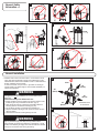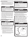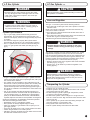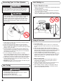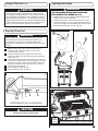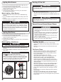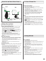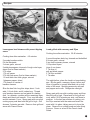
1
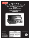
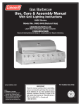
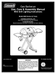
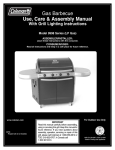
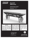
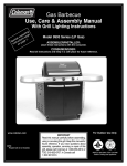
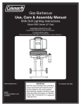
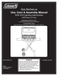
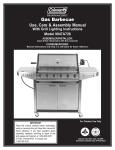
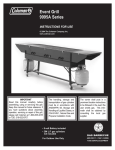
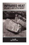
Gas Barbecue
Use, Care & Assembly Manual
With Grill Lighting Instructions
5100 LP Gas Series
5110 Natural Gas Series
ASSEMBLER/INSTALLER:
Leave these instructions with the consumer.
CONSUMER/USER:
Read all these instructions and keep them in a safe place for future reference.
For Outdoor Use Only
www.coleman.com
IMPORTANT
Read this manual carefully before assembling,
using or servicing this grill. Keep this manual for
future reference. If you have questions about
assembly, operation, servicing or repair of this
stove, please call Coleman at 1-800-835-3278
or TDD: 316-832-8707. In Canada call
1-800-387-6161.
CERTIFIED
®
®
Contents
WARNING
General Safety Information . . . . . . . . . . . . . . . . . . . . . . . . . . . . . . . . . . . . . . . . 2
General Installation . . . . . . . . . . . . . . . . . . . . . . . . . . . . . . . . . . . . . . . . . . . . . . 3
Electrical Attachments . . . . . . . . . . . . . . . . . . . . . . . . . . . . . . . . . . . . . . . . . . . . 4
Fuel Connections other than Portable L.P. Cylinders . . . . . . . . . . . . . . . . . . . . 4
Natural Gas Connections . . . . . . . . . . . . . . . . . . . . . . . . . . . . . . . . . . . . . . . . . 4
Portable L.P. Gas Barbecue Cylinders . . . . . . . . . . . . . . . . . . . . . . . . . . . . . . . 4
L.P. Gas Cylinder . . . . . . . . . . . . . . . . . . . . . . . . . . . . . . . . . . . . . . . . . . . . . . . . 5
Hose and Regulator. . . . . . . . . . . . . . . . . . . . . . . . . . . . . . . . . . . . . . . . . . . . . . 5
Transporting the Cylinder . . . . . . . . . . . . . . . . . . . . . . . . . . . . . . . . . . . . . . . . . 5
Filling and Purging Type 1 L.P. Gas Cylinders . . . . . . . . . . . . . . . . . . . . . . . . . 6
Purging and Evacuating Devices for L.P. Gas Cylinders
with Type 1 Cylinder Valves . . . . . . . . . . . . . . . . . . . . . . . . . . . . . . . . . . . . . . 6
Assembly/Set up . . . . . . . . . . . . . . . . . . . . . . . . . . . . . . . . . . . . . . . . . . . . . . . . 7
Connecting Type 1 L.P. Gas Cylinders . . . . . . . . . . . . . . . . . . . . . . . . . . . . . . . 26
Leak Testing. . . . . . . . . . . . . . . . . . . . . . . . . . . . . . . . . . . . . . . . . . . . . . . . . . . 26
Fixing a Fuel Leak . . . . . . . . . . . . . . . . . . . . . . . . . . . . . . . . . . . . . . . . . . . . . . 26
Start-Up Check List . . . . . . . . . . . . . . . . . . . . . . . . . . . . . . . . . . . . . . . . . . . . . . 27
Lighting Instructions. . . . . . . . . . . . . . . . . . . . . . . . . . . . . . . . . . . . . . . . . . . . . 27
Lighting Main Burners . . . . . . . . . . . . . . . . . . . . . . . . . . . . . . . . . . . . . . . . . . . 28
Lighting Side Burner . . . . . . . . . . . . . . . . . . . . . . . . . . . . . . . . . . . . . . . . . . . . 28
Shutting Off the Grill . . . . . . . . . . . . . . . . . . . . . . . . . . . . . . . . . . . . . . . . . . . . 28
General Use and Correct Burner Flames . . . . . . . . . . . . . . . . . . . . . . . . . . . . 28
Grilling Tips and Hints . . . . . . . . . . . . . . . . . . . . . . . . . . . . . . . . . . . . . . . . . . . 29
In Case of Grease Fire . . . . . . . . . . . . . . . . . . . . . . . . . . . . . . . . . . . . . . . . . . 29
Cooking methods. . . . . . . . . . . . . . . . . . . . . . . . . . . . . . . . . . . . . . . . . . . . . . . 29
Cleaning the Venturi . . . . . . . . . . . . . . . . . . . . . . . . . . . . . . . . . . . . . . . . . . . . 30
Cleaning and Maintenance . . . . . . . . . . . . . . . . . . . . . . . . . . . . . . . . . . . . . . . 30
Moving and Storage. . . . . . . . . . . . . . . . . . . . . . . . . . . . . . . . . . . . . . . . . . . . . 31
Troubleshooting . . . . . . . . . . . . . . . . . . . . . . . . . . . . . . . . . . . . . . . . . . . . . . . . 31
For Your Additional Safety . . . . . . . . . . . . . . . . . . . . . . . . . . . . . . . . . . . . . . . . 32
Registration Card. . . . . . . . . . . . . . . . . . . . . . . . . . . . . . . . . . . . . . . . . . . . . . . 33
Recipes . . . . . . . . . . . . . . . . . . . . . . . . . . . . . . . . . . . . . . . . . . . . . . . . . . . . . . 35
Warranty . . . . . . . . . . . . . . . . . . . . . . . . . . . . . . . . . . . . . . . . . . . . . . . Back Page
General Safety Information
This manual contains important information about the assembly, operation and maintenance of this product and system. General safety information is presented in these first few pages and is also located throughout the
manual. Particular attention should be paid to information accompanied by
the safety alert symbols: “ DANGER”, “ WARNING”, “ CAUTION”.
Keep this manual for future reference and to educate new users of this
product. This manual should be read in conjunction with the labeling on
the product.
Safety precautions are essential when any mechanical or propane
fueled equipment is involved. These precautions are necessary when
using, storing, and servicing. Using this equipment with the respect and
caution demanded will reduce the possibilities of personal injury or property
damage.
The following symbols shown below are used extensively throughout this
manual. Always heed these precautions, as they are essential when using
any mechanical or fueled equipment.
DANGER
DANGER indicates an imminently hazardous situation which, if not
avoided, will result in death or serious injury.
WARNING
WARNING indicates a potentially hazardous situation which, if not
avoided, could result in death or serious injury.
CAUTION
2
CAUTION indicates a potentially hazardous situation which, if not
avoided, may result in minor or moderate personal injury, or property
damage.
IF YOU
1.
2.
3.
4.
SMELL GAS:
Shut off gas to the appliance.
Extinguish any open flame.
Open lid.
If odor continues, immediately call your gas supplier
or your fire department.
5. NEVER use Natural Gas in a unit designed for Liquid
Propane (L.P.) Gas.
WARNING
FOR YOUR
SAFETY:
1. DO NOT Store or use gasoline or other flammable
vapors and liquids in the vicinity of this or any other
appliance.
2. An L.P. cylinder not connected for use shall NOT be
stored in the vicinity of this or any other appliance.
3. NEVER use Liquid Propane (L.P.) Gas in a unit
designed for Natural Gas.
WARNING
Combustion by-products produced when using this product contain
chemicals known to the State of California to cause cancer, birth
defects, or other reproductive harm.
DANGER
• FOR OUTDOOR USE ONLY. NEVER operate grill in enclosed
areas, as this could lead to gas accumulating from a leak, causing
an explosion or a carbon monoxide buildup which could result in
injury or death. DO NOT use in garages, breezeways, sheds or
any enclosed area. (Fig. 1)
• NOT FOR USE BY CHILDREN. (Fig. 2)
• If these instructions are ignored, a hazardous fire or explosion could
result in physical injury, death or property damage!
WARNING
• DO NOT move grill while it is lit. (Fig. 3)
• Keep outdoor cooking gas appliance area clear and free from
combustible materials, gasoline and other flammable vapors and
liquids. (Fig. 4)
WARNING
• NEVER place more than 15 pounds on a side table or a side burner.
DO NOT lean on grill. (Fig. 5)
• NEVER use charcoal briquettes or lighter fluid in a gas grill. (Fig. 6)
• Grill is hot when in use; to avoid burns, DO NOT touch any hot grill
surface. Keep children and pets away from hot grill. (Fig. 7)
• NEVER leave the grill unattended while it is in use. (Fig. 8)
• It is your responsibility to assemble, install, operate and care for
your gas grill properly.
• DO NOT vent propane vapor from the cylinder before taking it to be
refilled.
• DO NOT use gas grill indoors or store any propane cylinder(s) indoors,
including in the garage, breezeways, sheds or enclosed areas.
• Under some circumstances, propane may lose the distinctive odor
that was added. Keep the service valve closed and plugged or
capped (as recommended by the manufacturer) when the cylinder is
not connected to the appliance, including “empty” cylinders. Other
strong odors may hide or mask the odor of propane. Colds, allergies, sinus congestion, and the use of tobacco, alcohol or drugs
may impair your ability to detect the odor of propane.
General Safety
Information cont.
1
3
2
4
7
24"
8
5
6
General Installation
• Installation must conform with local codes or, in the absence of local
codes, with either the National Fuel Gas Code, ANSI Z223.1 (USA),
CAN/CGA-B149.1, Natural Gas Installation Code or CAN/CGA-B149.2,
Propane Installation Code (Canada).
To check local codes, see your local L.P. gas dealer or natural gas
company listed in the Yellow Pages for recommended installation procedures and regulations.
WARNING
9
Clear
36"
(90cm)
36"
(90cm)
36"
(90cm)
This appliance is not to be installed in or on a recreational vehicle
and/or boat.
Follow these safety rules before each use:
1. Always maintain a minimum clearance of 36 inches or 90 cm from
all sides of grill to any combustible construction. (Fig. 9)
2. Never locate grill under an unprotected combustible material or
overhang which is connected to a building. (Fig. 9a)
3. Do not obstruct the flow of combustion and ventilation air.
4. Keep the ventilation opening(s) of the cylinder enclosure free and
clear from debris.
5. Grill should be level and not facing directly into wind.
36"
(90cm)
REPRESENTATIVE
ILLUSTRATION
9a
WARNING
Keep any electrical supply cord away from any heated surface.
During assembly of grill and when attaching or replacing the L.P. gas
cylinder, insure that the gas supply hose is free of kinks and is at least
3" away from hot surfaces such as the grill housing.
3
Electrical Attachments
When using an electric attachment with grill, follow specification
and warning statements accompanying the attachment.
IMPORTANT: If using an external electrical source, the installed
appliance must be electrically grounded according to local codes
or, in the absence of local codes, with the National Electrical
Code, ANSI/NFPA 70 or the Canadian Electrical Code CSA
C22.1.
WARNING
Electrical Grounding instructions: An appliance
equipped with a three-prong (grounding) plug is for
your protection against shock hazard and must be
plugged directly into a properly grounded three-prong
receptacle. DO NOT remove grounding prong from a
three-prong plug.
Longer detachable power-supply cords or extension cords must
be used with care. The marked electrical rating of the cord set or
extension cord must be at least as great as the electrical rating of
the appliance. If the appliance is of the grounded type, the extension cord should be a grounding-type 3-wire cord. Use outdoor
extension cords with a surface marked with suffix letters “W-A”
and with a tag stating “Suitable for Use with Outdoor Appliances”.
Keep the connection to an extension cord away from water and
off the ground. Arrange the cord so that it will not drape over the
countertop or tabletop where it can be pulled on by children or
tripped over unintentionally.
Never clean any electrical product with water or cleaning fluids.
Store electrical products indoors and out of reach of children
when not in use. DO NOT allow cord to touch any hot surfaces
which could melt insulation.
LP Fuel Connections Other Than
Portable L.P. Cylinders
CAUTION
• This section applies to L.P. Gas (Propane) Grills and only
where propane gas is to be piped to the grill.
• Natural gas can be used only with grills which have been
equipped for use with natural gas.
If the appliance is for connection to other than an L.P. cylinder
(consult the Assembly Instructions) the gas connections must be
made by a qualified installer or a licensed plumber. The gas supply line must not be installed by the consumer.
The maximum inlet supply pressure is 13.0" w.c. for propane gas.
The specified supply pressure is 11.0" w.c. for propane gas.
Natural Gas Connections
WARNING
• Gas supply system must be installed in accordance with the U.S.
National Fuel Gas Code.
• This appliance and its individual shut off valve must be disconnected
from the gas supply piping system during any system pressure test in
excess of 1/2 PSI (3.5 KPA).
• Use a system manual shut off valve to shut off the gas supply to this
gas appliance before continuing with installation procedures.
The maximum inlet supply pressure is 10.5" w.c. for natural gas.
The specified supply pressure is 7.0" w.c. for natural gas.
WARNING
A liquid propane tank, not connected for use with this gas barbecue,
shall not be stored in the vicinity of this or any other appliance.
Installation and provision for combustion and ventilation air
must conform with the National Fuel Gas Code, ANSI Z223.1,
or CAN/CGA-B149.1, Natural Gas Installation Code, or
CAN/CGA-B149.2, Propane Installation Code.
Connections must comply with local requirements and are the
sole responsibility of the person performing the work. A certified plumber must make connection to gas source.
Portable L.P. Gas Barbecue Cylinders
Liquefied Petroleum gas (abbreviated L.P. gas or propane), is
highly flammable. It becomes liquid when stored under high pressure inside a cylinder and vaporizes when released. L.P. gas is
heavier than air and tends to collect in low areas. It is important
that there are no leaking connections on your gas grill that could
cause a fire or explosion (see “LEAK TESTING”, Pg. 26).
Portable LP gas grills require a fuel delivery system which is
comprised of a valve [A], a hose [B], a regulator [C] with vent hole
[G], an L.P. gas supply cylinder [D], a Type 1 coupling nut [E] and
a Type 1 cylinder valve [F]. (Fig. 10). Illustration in Fig. 10 is for
description purposes only. The valve assembly for this grill is of a
different configuration.
WARNING
Your new barbecue grill is equipped with a Type 1 coupling
nut [E]. DO NOT attempt to connect to any other L.P. cylinder
not equipped with a mating Type 1 cylinder valve [F]. This grill
is not to be used with any other cylinder connection device.
10
A
D
THE PIPING SYSTEM MUST BE INSTALLED IN ACCORDANCE
WITH NATIONAL FUEL GAS CODE IN THE USA, INCLUDING:
1. The appliance and its individual shut-off valve must be disconnected from the gas supply piping system during any
pressure testing of that system at test pressures in excess
of 1/2 psi (3.5 kPa).
2. The appliance must be isolated from the gas supply piping
system by closing its individual manual shut-off valve during
any pressure testing of the gas supply piping system at test
pressures equal to or less than 1/2 psi (3.5 kPa).
4
F
B
E
C
G
L.P. Gas Cylinder
DANGER
• DO NOT insert any foreign objects into the valve outlet.
You may damage the valve. A damaged valve can cause
a leak, which could result in explosion, fire, severe personal injury or death.
WARNING
• Cylinders must be stored outdoors out of the reach of
children and must not be stored in a building, garage or
any other enclosed area. (Fig. 11)
Cylinder Specifications
• Any L.P. gas supply cylinder used with this grill must be
approximately 12 inches diameter and 18 inches high. The
maximum fuel capacity is 80% and is approximately 20 pounds
of propane.
• The maximum weight of a properly filled cylinder will be
approximately 38 pounds (47.7 lbs. nominal water capacity).
• The L.P. cylinder must have a shut-off valve terminating in a
Type 1 L.P. gas cylinder valve outlet (see item [F], Fig. 10,
pg. 4).
11
L.P. Gas Cylinder cont.
CAUTION
Have the gas dealer weigh cylinder after filling to ensure that
the cylinder is not overfilled.
Hose and Regulator
The Type 1 connection system has the following features:
1.The system will not allow gas to flow until a positive connection
has been made.
NOTE: The cylinder control valve must be turned off before any
connection is made or removed.
2.The system has a thermal element that will shut off the flow of
gas in the event of a fire.
3.The system has a flow limiting device which, when activated, will
limit the flow of gas to 10 cubic feet per hour.
4.NEVER use grill without leak testing this connection.
WARNING
• DO NOT attempt to adjust the regulator as this could
create a situation causing personal injury or property
damage.
The pressure regulator and hose assembly with the Type 1 fitting
supplied with the appliance must be used. Do not use another
hose and regulator assembly other than the one supplied with the
grill or a Coleman replacement pressure regulator assembly. The
pressure regulator and hose assembly provided is factory set at
an outlet pressure of 11 inches water column (1/2 psi).
• Keep the small vent hole in the regulator clean of dirt and debris
(see item [G], Fig. 10, pg. 4).
• Consult your L.P. gas dealer if you think the regulator is not
working properly.
WARNING
• A Type 1 compatible cylinder with a Type 1 cylinder valve has
a back-check valve which does not permit gas flow, until a positive seal has been obtained.
• The cylinder must be arranged for vapor withdrawal. It must
also include a collar to protect the cylinder valve. A safety relief
device having direct communication with the vapor space of
cylinder must be provided. This will expel high pressure gas if
the cylinder is overfilled or overheated which could result in fire
or explosion.
• All L.P. gas cylinders used with this appliance shall be constructed and marked in accordance with the specifications for
L.P. gas cylinders of the U. S. Department of Transportation
(DOT) or the National Standard of Canada, CAN/CSA-B339,
Cylinders, Spheres and Tubes for Transportation of Dangerous
Goods; and Commission, as applicable; and shall be provided
with a listed overfilling prevention device.
• Read labels on the L.P. Gas Supply Cylinder.
• New cylinders are always shipped empty for safety.
• Allow only qualified L.P. gas dealers to fill or repair your L.P.
gas supply cylinder.
• Inform the gas dealer if it is a new or used cylinder to be filled.
• Caution the gas dealer not to overfill cylinder.
• After filling, have the gas dealer check for leaks and to see that
the relief valve remains free to function.
During assembly of grill and when attaching or replacing
the L.P. gas cylinder, insure that the gas supply hose is free
of kinks and/or damage and is at least 3" away from hot surfaces such as the grill housing.
Transporting the Cylinder
• Transport only one cylinder at a time.
• Transport cylinder in an upright and secure manner with a control
valve turned off and the cap in place.
• DO NOT transport cylinder in passenger compartment, unless
you have an open window ventilation.
• DO NOT leave cylinder in direct sunlight or in a high heat area
such as a closed car trunk. High heat areas could cause the relief
valve to vent gas.
• Use a cylinder cap on cylinder valve outlet during transport and
when the cylinder is not connected to grill.
• Keep cylinder valve closed when not in use.
• Take the cylinder directly home after it has been filled.
5
Transporting the Cylinder cont.
Filling and Purging Type 1
L.P. Gas Cylinders cont.
WARNING
Handle a full cylinder with care. Gas is under high pressure.
13
CGA-510 POL
DANGER
• NEVER store a spare L.P. gas supply cylinder under the
grill body or inside grill enclosure or in the vicinity of any
heat producing appliance. (Fig. 12)
• NEVER fill the cylinder beyond 80% full.
Failure to follow this information exactly could result in an
explosion and/or fire causing death or serious injury.
12
Purging and Evacuating Devices for L.P.
Gas Cylinders with Type 1 Cylinder Valves
CAUTION
After purging or filling an L.P. Gas cylinder, DO NOT insert a
POL plug into the valve outlet. Insertion of the plug will prevent the back-check from closing. Use ONLY the provided
cap and strap attached to the outlet. Close the cylinder valve
knob before returning the cylinder to the customer.
For proper purging procedures refer to:
In the US: Safety Bulletin NPGA# 133, “Purging L.P. Gas
Cylinders”, and Safety Bulletin NPGA #130, “Recommended
Procedures for Filling Cylinders”.
Filling and Purging Type 1
L.P. Gas Cylinders
Take these instructions to the L.P. gas dealer.
DANGER
Purging and filling of L.P. Gas cylinders must be performed
by personnel who have been thoroughly trained in accepted
L.P. Gas industry procedures. Failure to follow this instruction may result in explosion, fire, serious personal injury, or
death.
• When using cylinder exchange: If your grill is equipped with a
Type 1 cylinder, be sure the exchanged cylinder is a Type 1
cylinder, as a 510 POL cylinder will not fit Type 1 regulator.
• This tank is easily filled with a standard CGA 510 POL filling
connection. (Fig. 13)
• New cylinders must be purged before filling. Tell your L.P. Gas
dealer if your cylinder is new and has not been previously filled.
The L.P. Gas cylinder has a Type 1 cylinder valve with a backcheck module in its outlet which will not permit gas to flow until
an evacuation device is installed. To purge the L.P. Gas cylin
der, the back-check module must be opened with an evacuation
device.
6
A. Hose end valve with a bleed port (Fig. 13):
Purging can be accomplished using a hose end valve
containing a bleed port which also allows for evacuation without
the use of an adapter.
B. Hose end valve without a bleed port:
When a hose end valve does not have a bleed port, a separate
device must be used for evacuation.
C. Purging using a Type 1 connection (Fig. 14):
L.P. Gas cylinder evacuation can be accomplished during each
purging by using a Type 1 connection. The Type 1 valve outlet
has an external 1 5/16" ACME right-hand thread which will
accept this connection.
14
TYPE 1
Assembly/Set up
■ Remove components from package.
Left Side Burner Electrode
Firebox
Right
Side Table
Left Side
Burner
Table
Rear Trim Plate
Warming Rack
Grates
Rear Support
Top Panel
Grease Pan
Cylinder
Support
Cylinder
Retaining Bolt
Grease
Cup
Grease
Cup
Support
Burner Heat Tents™
9-Volt
Battery
Right
Panel
Electrode Module
Left
Panel
Tool
Hook
Side Burner
Door
Magnets
Base
Left
Door
Right Door
Locking
Casters
Side Burner Knob
Non-Locking
Casters
Side
Burner
Grate
7
Ö
NOTE: Use a large piece of cardboard or a ground
cloth to protect the painted finish on the grill.
Step
1
1-A
Right Panel
Hardware shown actual size
(TN)
M6 x 15mm Screw
(10) Qty.
TN
Base
Left Panel
1-A. Arrange the two panels and the base on the ground as shown.
Ö LOOSELY assemble the Right Panel and the Left Panel to the Grill Base
using one screw (TN) in each top corner.
1-C
1-B
TN (x2)
Left
Panel
Flange
TN (x2)
TN (x2)
1-B. LOOSELY assemble two fasteners (TN) into each bottom
corner from the outside.
8
1-C. LOOSELY assemble two fasteners (TN) through the Left
Panel Flange into the Base (as illustrated).
Ö Repeat Step 1-C on the Right Panel Flange.
Ö
Step
2
Carefully turn the assembly
up-side-down to perform
Step 2. This will give easy
access to assemble the
parts in Step 2.
Hardware shown actual size
2-C
TN (x2)
(TN)
M6 x 15mm Screw
(8) Qty.
2-A
Base (up-side-down)
2-A. Carefully turn the grill Up-Side-Down.
2-A. Carefully turn the grill Up-Side-Down.
See Detail 2-C
2-B
TN (x4)
2-D
Locking
Casters
NonLocking
Casters
Front
TN (x4)
Back
2-B. Assemble eight additional screws (TN) to fasten the Side
Panels to the base Base.
Ö Tighten all fasteners.
2-D. Fasten Casters tight against the Caster Brackets.
9
Ö
Step
3
NOTE: Use a ground cloth
to protect the paint finish
during this step.
4-A
AV (x2)
BW (x2)
3-A
Electronic Module
4-A. Attach the Electronic Module to the Left Panel on the
inside surface. Use two screws (AV) and two locking hex
nuts (BW).
4-B. Assemble the Cylinder
Retaining Bolt to the
Cylinder Support.
4-B
2-A. Carefully turn the grill Up-Side-Down.
Locking Casters
3-A. Check that all fasteners are tightened before turning the
grill Right-Side-Up.
Ö Carefully turn the grill Right-Side-Up.
Ö Engage the Locking Casters to prevent movement during
the rest of the assembly process.
Hardware shown actual size
(VP)
Self Tapping Screw
(1) Qty.
Step
4
4-C
4-C. Assemble the Cylinder
Support to the Base by
engaging the tabs in
the slots. Secure the
support with one screw
(VP).
VP
Hardware shown actual size
(AV)
M5 x 10mm Screw
(2) Qty.
(BW)
M5 Locking Hex Nut
(2) Qty.
Cylinder Support
10
Ö
Ö
Step
5
Assemble the Top Panel.
Assemble the Rear
Support.
Ö
Install Door Magnets.
Step
6
Hardware shown actual size
Hardware shown actual size
(TN)
M6 x 15mm Screw
(16) Qty.
(TN)
M6 x 15mm Screw
(4) Qty.
5-A
(UO)
M6 Locking Hex Nut
(2) Qty.
6-A
Door Magnet
Top Panel
TN (x2)
UO (x2)
TN (x8)
5-A. Assemble the Top Panel to the Left and Right Side Panels
with eight Screws (TN).
5-B
Rear Support
6-A. Assemble the Door Magnet to the Top Panel with two
Screws (TN) and two Locking Hex Nuts (UO).
6-B
Door Magnet
TN (x2)
TN (x8)
5-B. Assemble the Rear Support to the Left and Right
Side Panels with eight Screws (TN).
6-B. Assemble one Door Magnet to the Base with two Screws
(TN).
11
Ö
Step
7
Ö
7-B
NOTE: Use a ground cloth
to protect the paint finish
during Step 7 and 8.
Assemble Right Side Table
to the Firebox.
Hardware shown actual size
(CX)
M6 x 20mm Screw
(5) Qty.
CX (x2)
(UO)
M6 Locking Hex Nut
(1) Qty.
7-C
CX
7-A
UO
FIREBOX
RIGHT
SIDE
TABLE
7-A. Lay the Firebox on it’s backside with lid closed . This
will allow easy access to the fastener locations.
Ö Assemble the Right Side Table to the Firebox with
five Screws (CX) and one Locking Hex Nut (UO).
Place the Locking Hex Nut in the center position as
shown in 7-C.
Ö Tighten all fasteners.
12
7-D
CX (x2)
Ö
8-B
Assemble Left Side Burner
Assembly to the Firebox.
Step
8
CX (x2)
Hardware shown actual size
(CX)
M6 x 20mm Screw
(5) Qty.
(UO)
M6 Locking Hex Nut
(1) Qty.
8-C
8-A
FIREBOX
UO
CX
8-D
Left Side
Burner Table
8-A. Assemble the Left Side Burner Table to the Firebox with
five Screws (CX) and one Locking Hex Nut (UO). Place
the Locking Hex Nut in the center position as shown in
8-C.
Ö Tighten all fasteners.
CX (x2)
13
Ö
Step
9
Ö
Assemble Firebox to the
Grill Cart.
HINT: A second person is
helpful when aligning the
Firebox to the Grill Cart.
9-C
9-A
FIREBOX
9-C. Make sure the Firebox panel is located on the INSIDE of
the Left Panel.
GRILL
CART
9-A. Carefully place the Firebox onto the Cart Assembly. Take
care to not damage the fuel hoses. They must be routed
through the large hole in the top panel. See Step 9-B.
9-D
9-B
9-D. Make sure the Firebox panel is located on the INSIDE of
the Right Panel.
9-B. While lowering the Firebox, route the fuel hoses through
the large hole in the top panel.
14
Ö
Fasten the Firebox to the
Grill Cart.
Hardware shown actual size
Step
10
(TN)
M6 x 15mm Screw
(6) Qty.
(DY)
M6 Flat Washer
(4) Qty.
(UO)
M6 Locking Hex Nut
(4) Qty.
10-A
TN (x3)
UO (x2)
DY (x2)
10-A. LOOSELY fasten the right side of the Firebox to the Grill Cart with three
Screws (TN), two Flat Washers (DY) and two Locking Hex Nuts (UO).
Ö NOTE: You will tighten these screws LATER (after Step 10-B), after the left
side of the Firebox is attached to the Grill Cart (this helps with alignment).
10-B
DY (x2)
TN (x3)
UO (x2)
10-B. Fasten the left side of the Firebox to the Grill Cart with three Screws
(TN), two Flat Washers (DY) and two Locking Hex Nuts (UO).
Ö Tighten all fasteners.
15
Ö
Fasten the Rear Trim Plate
to the Grill Cart.
Step
11
Hardware shown actual size
(VP)
Self Tapping Screw
(2) Qty.
11-A
FIREBOX
REAR
TRIM
PLATE
11-B
REAR
TRIM
PLATE
VP (x2)
11-B. View showing Rear Trim Plate properly installed.
11-A. Fasten the
Rear Trim
Plate to the
Firebox with
two Screws
(VP).
Ö Tighten all
fasteners.
VP
16
Ö
Step
12
Ö
Fasten both Left and Right
Doors to the Grill Cart.
Attach the Tool Hook to the
Right Door.
Hardware shown actual size
(XR)
M5 x 15mm Flat Head Screw
(8) Qty.
12-A
12-C
TOOL HOOK
XR (x4)
LEFT DOOR
RIGHT DOOR
12-C. Fasten the Right Door to the Grill Cart with four Flat
Head Screws (XR).
Ö Repeat Step 12-C to attach the Left Door.
Ö Tighten all fasteners.
5-B
TOOL HOOK
12-B. Squeeze the Tool Hook to slip into the mounting
brackets.
17
Ö
Ö
Step
13
13-A
Ö
Install three Heat Tents™.
Install three Cooking
Grates.
Install the Warming Rack.
Warming
Rack
13-B
Heat
Tents™
13-B. Install three Heat Tents™ over the Burners.
Ö The Heat Tents™ are located using the alignment pins.
13-C
Cooking
Grates
Standard
Grate
Power
Grate
Standard
Grate
Heat
Tents™
Burners
13-C. Install three Cooking Grates, flat side downward.
Ö Locate the Power Grate in the center position.
13-D
18
Warming
Rack
13-D. Place the Warming Rack in the back of the Firebox.
Ö Align four posts downward into four holes.
Ö
Install the Side Burner
Valve.
Step
14
Hardware shown actual size
(WQ)
M4 X 10mm Screw
(2) Qty.
14-A
14-B
Side
Burner
Valve
Large
Hole
14-D
14-A. Route the Side Burner Valve through the Large Hole in
the Left Panel.
14-C
View
from
Above
WQ (x2)
14-E
Side
Burner
Valve
View From Back of Grill
14-C. Attach the Side Burner Valve with two Screws (WQ).
View
from
Below
19
Ö
Step
15
Ö
Assemble the Side Burner
to the Left Side Table.
Assemble the Electrode to
the Side Burner.
15-A
Hardware shown actual size
(ZT)
(WQ)
Hair Pin
M4 X 10mm Screw
(1) Qty.
(1) Qty.
(Attached to Burner)
(YS)
M4 Hex Nut
(1) Qty.
15-C
ZT
YS
WQ
15-A. Slip the Burner Tube through the Left Side Table.
15-B
Burner
Valve
15-B. Align Burner Tube with Burner Valve.
Ö NOTE: Make sure Burner Valve is inserted into Burner
Tube.
20
15-C. Lock the Side Burner in place with one hairpin (SS).
Ö Install electrode as shown with one screw (WQ) and one
hex nut (YS).
15-D
Burner
Tube
Electrode
Caution: Assemble the
wires BELOW the burner
tubes!
15-D. View showing Side Burner properly installed.
Assemble the Electrode
Wires and the Battery to the
Electrode Module.
Note: The fuel hoses are not
shown in this step, for
simplicity.
Ö
Step
16
16-A
Top Burner Wires
9-Volt Battery
Electrode Module
16-A. Slip the Top Burner Wires through the
large hole in the Top Panel.
Ö Slip the Side Burner Wire through the
large hole in the Left Panel.
Ö Assemble the 9-Volt Battery to the
Electrode Module.
Note: The polarity is marked on the Electrode
Module.
Side Burner Wire
16-B
Electrode Module
9-Volt Battery
Igniter Button Wires
(Note: Large Tabs)
TEST THE IGNITER:
A SPARK SHOULD APPEAR AT
ELECTRODE TIP.
IF THE SPARK DOES NOT
APPEAR:
-CHECK THE WIRE
CONNECTIONS TO THE
MODULE.
-CHECK PROPER
ASSEMBLY OF FRESH
9-VOLT BATTERY.
Side Burner
Electrode Wire
21
Ö
Step
17
Install Side Burner Knob
and Side Burner Grate onto
the Left Side Burner.
Assemble the Grease Cup
Support to the Grease Pan.
Note: The Grease Pan is shown
up-side-down during this step.
Ö
Step
18
Hardware shown actual size
(VP)
Self Tapping Screw
(2) Qty.
18-A
17-A
Side
Burner
Grate
Side
Burner
Knob
VP (x2)
Grease
Cup
Support
Note: Small
Surface
here.
Grease
Pan
17-A. Place the Side Burner Knob on the valve stem.
Ö Place the Side Burner Grate on the Left Side Burner.
Align the pins downward into the alignment holes.
Note: Lip
is up.
22
18-A. Attach the Grease Cup Support to the Grease Pan with
two self-tapping screws (VP).
Ö
Ö
Install the Grease Pan.
Install the Grease Cup.
Step
19
19-A
Grease Pan
Rear Support
19-A. Slide the Grease Pan Assembly into the back of the grill.
Ö Tilt the pan slightly upward until the Grease Cup Support
clears the Rear Support.
19-B
Grease Cup
19-B. Place the Grease Cup into the Grease Cup Support.
Note: Pull the Grease Pan outward slightly for easier access
when installing/removing the Grease Cup.
Ö After the Grease Cup is installed, push the Grease Pan
forward until it contacts the location stops.
23
NOTE: Step 20 applies to you only if your grill is set up from the factory to use LP GAS. If your grill is set up from the factory to
use NATURAL GAS, skip to Step 21.
Ö
Attach an LP Cylinder to the
Grill.
20-C
Step
20
20-A
LP Cylinder
Type 1 Nipple
Cylinder Support
20-A. Set LP Cylinder in the Cylinder Support with the outlet
valve facing toward the front of the grill.
Fuel Valve Outlet
20-C. Insert the TYPE 1 Nipple of the regulator into the cylinder’s Fuel Valve Outlet as shown. Turn the regulator
hand wheel clockwise to tighten. No tools are needed.
The hand wheel will come to a complete stop when the
connection is secure, and gas will not flow until a positive
seal is achieved.
20-B
IMPORTANT!
TO ENSURE PROPER GAS FLOW, BURNER
CONTROL VALVES MUST BE “OFF” BEFORE
OPENING THE GAS CYLINDER VALVE.
WARNING: During assembly of
Cylinder Hold-Down Bolt
20-B. Tighten the Cylinder Hold-Down Bolt against the bottom
cylinder collar.
24
grill and when attaching or replacing the
L.P. gas cylinder, insure that the gas supply hose is free of kinks and/or damage
and is at least 3” away from hot surfaces
such as the grill casting.
NOTE: Step 21 applies to you only if your grill is set up from the factory to use NATURAL GAS. If your grill is set up from
the factory to use LP GAS, skip back to Step 20.
Ö
Ö
Attach a NATURAL GAS
line to the grill.
Step
21
YOUR NATURAL GAS COMPANY MUST INSTALL AND CONNECT THE
GAS SUPPLY LINE TO THE GRILL.
21-A
PLACE THE RUBBER PLUG ONTO THE GAS SUPPLY LINE. THEN
ATTACH THE SOCKET END OF THE QUICK DISCONNECT COUPLING
ONTO THE GAS SUPPLY LINE. TIGHTEN WITH A WRENCH.
LEAK TEST AT THE FUEL SOURCE CONNECTION WITH SOAP AND
WATER. THE RUBBER PLUG IS USED TO PROTECT THE CONNECTOR WHEN THE HOSE CONNECTOR IS NOT INSERTED.
POSITION THE RUBBER CAP ONTO THE HOSE CONNECTOR.
USE THE CAP IS TO COVER THE HOSE CONNECTOR WHEN NOT
ATTACHED TO THE FUEL SOURCE.
CAUTION: MAKE SURE THE GAS CONTROL KNOBS
ARE IN THE “OFF” POSITION BEFORE CONNECTING THE LOWER
END OF THE HOSE TO THE FUEL SOURCE.
Rubber Plug
TO CONNECT AT THE FUEL SOURCE: PUSH BACK THE SLEEVE OF
THE QUICK DISCONNECT COUPLING AND INSERT THE HOSE CONNECTOR. RELEASE THE SLEEVE AND PUSH THE CONNECTOR INTO
THE COUPLER UNTIL THE SLEEVE SNAPS FORWARD.
TO DISCONNECT AT THE FUEL SOURCE: PUSH BACK THE SLEEVE
AND PULL OUT THE CONNECTOR. THIS AUTOMATICALLY SHUTS
OFF THE GAS. IMMEDIATELY PLACE THE RUBBER PLUG INTO THE
QUICK DISCONNECT END.TURN OFF THE FUEL SOURCE SHUT-OFF
VALVE IF APPLICABLE.
WARNING: DURING ASSEMBLY OF GRILL AND WHEN
Quick Disconnect Coupling
CONNECTING OR DISCONNECTING THE HOSE FROM THE FUEL
SUPPLY LINE, INSURE THAT THE GAS SUPPLY HOSE IS FREE OF
KINKS AND/OR DAMAGE AND IS AT LEAST
3” AWAY FROM HOT
SURFACES SUCH AS THE GRILL CASTING.
21-B
21-C
Rubber Cap
Hose Connector
Quick Disconnect Coupling
25
Connecting Type 1 L.P. Gas Cylinders
WARNING
This procedure MUST be performed OUTDOORS only! Be
sure L.P. cylinder valve is closed. Attach to Grill. Read and
follow directions on the cylinder and fuel hose safety tags.
CAUTION
In the connection process, the grill side of the connection will
seal on the back-check in the valve, resulting in a slight
resistance. The connection requires about one-half to threequarters additional turn to complete the connection. To disconnect, turn counterclockwise. Tighten by hand only. DO
NOT use tools.
Leak Testing (cont.)
How to Check for Leaks
1. Make a soapy solution of equal parts mild liquid dishwashing
detergent and water.
2. Turn off all burner control knobs.
3. Turn on fuel supply. Turn cylinder valve knob counterclockwise (right to left) one rotation.
4. Apply soap solution to connections indicated with arrows in
Fig. 16. If bubbles appear at these areas, a leak is indicated.
16
15
Fixing A Fuel Leak
1. Check that the cylinder valve is closed by turning the cylinder
knob clockwise to a full stop.
2. Check that all the grill burner knobs are in the off position.
3. Remove the protective caps from the cylinder valve and cou pling nut. NOTE: The coupling nut connects to the large outside
threads on the valve outlet.
4. Hold the regulator in one hand and insert the nipple into the
valve outlet. Be sure the nipple is centered in the valve outlet.
Hand-tighten the coupling nut, taking care not to cross-thread
the connection (see Fig. 15).
5. Turn the coupling nut clockwise, tighten to a full stop.
If you cannot complete the final connection, disconnect the regulator and repeat steps 4 through 6. If you are still unable to
complete the connection, DO NOT use this valve and regulator!
6. Check that the hose has no kinks or sharp bends and clears
areas that will become hot during use. Never put strain on the
hose where it joins a fitting.
7. BEFORE lighting grill, check all connections for leaks using the
procedure as shown in Fig. 16 on pg. 26.
Leak Testing
DANGER
TO PREVENT FIRE OR EXPLOSION HAZARD:
• NO SMOKING. DO NOT use or permit sources of ignition
in the area while doing a leak test.
• Perform leak tests outdoors only.
• NEVER perform a leak test with fire or flame.
26
• If you detect a leak:
1. Turn off the fuel supply. Push in and turn on control knobs
to release pressure in hose, then turn the control knobs back
to off.
2. Wash off soapy solutions with cold water and towel dry.
3. Stop a leak by tightening the loose joint, or by replacing the
faulty part with a replacement part recommended by Coleman.
DO NOT attempt to repair the cylinder valve if it should
become damaged; the cylinder MUST be replaced.
4. If you are unable to stop a leak, shut off the gas supply at the
cylinder valve. Remove the cylinder from the grill. Call a gas
appliance serviceman or L.P. gas dealer. DO NOT use grill
until the leak is corrected.
• When to test for leaks:
1. Perform a leak test each time the gas supply cylinder is
connected to the regulator. Leak test anytime a part of
the gas system is replaced.
2. Perform a leak test at least once each year whether the L.P.
gas supply cylinder has been disconnected or not.
3. Have a dealer check the cylinder for deterioration after 12
years, according to DOT regulations. Immediately replace
cylinder if any deterioration is found.
Fixing A Fuel Leak (cont.)
Lighting Instructions
WARNING
CAUTION
Inspect the gas supply hoses before each use. If there are
cuts, damage, excessive abrasion or wear, replace the hoses
prior to operating the appliance. During assembly of grill and
when attaching or replacing the L. P. gas cylinder, insure that
all gas supply hoses are free of kinks and/or damage and are
at least 3" away from hot surfaces such as the grill housing.
Use only hose replacements specified in the parts list.
THE FOLLOWING RULES MUST ALWAYS BE
FOLLOWED IN THIS ORDER (Fig. 18):
1. OPEN GRILL LID! Any attempt to light the grill with the
lid down could cause an explosion.
2. Check that the burner control knobs are turned to “OFF”.
3. Turn on fuel supply. For an L.P. gas cylinder, turn the top
cylinder valve knob counterclockwise one rotation to open.
4. DO NOT stand with head or arms over grill.
Start-Up Check List
18
3
WARNING
Failure to follow these safety steps before using grill each
time could result in a fire that could be hazardous to you,
your appliance or property. It is especially important to
observe these steps after the grill has been stored, moved or
cleaned.
4
1. Regularly check burner venturi tubes for blockage from an
insect nest. Read “Cleaning the Venturi” on pg. 30 and
“Troubleshooting” on pg. 31.
2. Check that all burner venturi [H] are set over the valve
outlets [J] correctly. The valve orifice [K] must be inside the
venturi. (Fig. 17)
3. Inspect the gas supply hoses before each use. Hoses can
be burned or chafed if they are routed improperly. See that
hoses have no kinks, sharp bends or tension. Insure that
hoses are at least 3 inches away from any hot surface.
4. Use only the gas specified.
5. Keep the grill on a level surface.
6. Keep grease pan empty at start up.
1
2
17
19
J
K
H
Igniter Switch
REPRESENTATIVE ILLUSTRATION
CAUTION
DO NOT add charcoal or lighting fluid!
LEFT
SIDE
BURNER
KNOB
Control Knobs for Main Cooking Area
27
Lighting Main Burners
Shutting Off the Grill
1. Turn on any or all burner gas control knobs to high. (Fig. 19)
2. Press the igniter switch until the flame ignites.
3. If the flame doesn’t immediately light, turn off control knob and
wait five minutes for gas to clear.
4. Repeat steps 1 through 3.
5. If the burner does not light on second try, turn off knob and
try match-lighting the burner.
Match Lighting - Main Burners
1. Strike and place the burning match near the BURNER being
operated.
2. Turn on BURNER CONTROL KNOB while holding match near
burner.
3. The other burners can be ignited by turning them on one at a
time after first burner is lighted.
CAUTION
DO NOT touch hot grill parts with bare hands! You MUST
use protective gloves.
1. Turn all burner control knob(s) to off.
2. After burner flame goes out, turn off fuel supply. For an L.P.
cylinder, turn the L.P. cylinder knob in a clockwise direction until
it stops.
CAUTION
Be certain the gas is shut off at the L.P. cylinder valve anytime the grill is not in use.
CAUTION
Use a LONG wooden match. Make sure all burner controls
are off except one being lighted. If a long-reach match or
lighter is not accessible, there is a match extension provided,
attached underneath the side burner table. Insert a match in
the holder end of the extension, strike the match, and insert it
through the match-lighting hole.
General Use and Correct Burner Flames
WARNING
• Keep grill area clean and free from combustible materials,
gasoline and other flammable vapors, liquids, and spare
L.P. cylinders.
• DO NOT obstruct the flow of combustion and ventilation air.
• Keep the ventilation opening(s) of the L.P. cylinder enclosure free and clear of debris.
• A barbecue grill becomes hot during use. DO NOT touch
grates, or cooking surfaces.
• Be sure to tighten all hardware (screws, nuts, bolts, etc.)
at least once a year or each grilling season.
Lighting Side Burner
1. Turn on side burner gas control knob to high. (Fig. 20)
2. Press the igniter switch until the flame ignites.
3. If the flame doesn’t immediately light, turn off control knob and
wait five minutes for gas to clear.
4. Repeat steps 1 through 3.
5. If the burner does not light, turn off knob and try match-lighting
the burner.
Condition The Grill
Match Lighting - Side Burner
CAUTION
Use a LONG wooden match or match extension.
1. Strike and place the burning match near the BURNER being
operated.
2. Turn on SIDE BURNER CONTROL KNOB while holding match
near burner.
WARNING
• Grill must be level before using side burner.
• NEVER move grill with a pot or pan on the side burner.
• Make sure pot or pan is centered on side burner. (Fig. 20a)
• To avoid the possibility of tipping over the grill, NEVER place
more than 15 pounds on the side burner. A filled 6-quart
aluminum pot weighs approximately 15 pounds.
20
20a
INCORRECT
CORRECT
28
•
•
Before using the grill for the first time or after storage,
operate grill 15 minutes on high setting, with lid closed, to burn
away oil.
Once the oil has burned away, check the burner flame per
next step.
The Burner Flame
•
•
•
Keep the grill lid closed and the cooking surfaces in place.
Observe the burner’s flame from below the grill bottom.
Flames should appear similar to the good flame shown in
Fig. 21 and as follows:
• A good flame should be blue with yellow tip.
• Some yellow tips on flames up to 1" in length are acceptable as long as no carbon or soot deposits appear.
• If flames are excessively yellow and irregular, the oil
residue may not be completely burned off, or the venturi
may be clogged or may not be properly positioned over the
orifices. Allow grill to cool before repositioning venturi over
valve and orifices.
• Grills that have been in use for a while sometimes begin to
show more yellow flame. A build-up of food deposits, fats
or cooking seasonings can cause yellowing flames.
Clean the burner to remove residue and check for clogged
burner holes or blocked venturi (see “Cleaning the Venturi”
pg. 30).
• Regular use of your grill will actually help keep it operating
more smoothly.
• Each grill may heat differently. Some units will heat somewhat more to the center and back of grill. Flavor of grilled
food will improve the more you use the grill and as you become
familiar with it.
In Case of Grease Fire
General Use and Correct Burner Flames cont.
21
Follow These Steps:
Yellow
Good
Bad
Yellow
Blue
Blue
1. Shut off gas at the burner valve(s) and stay away!
2. Allow the fire to burn itself out.
3. Once the fire is out and the appliance has cooled, shut off the
L.P. cylinder valve.
4. Clean all parts and inspect for damage. Parts to check for
damage are the L.P. cylinder, cylinder valve, regulator, gas
supply hose, burner valve(s) and burner(s).
5. If any of the above mentioned components are damaged,
seek replacement from Coleman before operating the grill
again. Locate your nearest service center by calling
1-800-835-3278.
Note:
•
Holes in
Burner
•
•
•
Grilling Tips and Hints
•
Some flare-up adds a smoky flavor and sears food. Excessive
grease fires can cause a potentially hazardous situation and
damage the grill.
Avoid excessive flare-ups by preheating the grill with the lid
closed for 5 minutes on high setting to burn off grease from
previous cooking.
Cook with lid down and continually monitor cooking food to
avoid grease fires and flare-ups.
Trimming excess fat from meat will reduce grease fires and
flare-ups. Cook fatty meat in smaller amounts over indirect
heat on low setting.
Be sure to follow the “Cleaning and Maintenance Instructions.”
Burner Control Setting Tips
• The high flame setting is too hot for direct cooking. The high
flame setting is good for quick searing of meat, then finish
cooking on medium or low flame settings.
• Use high flame setting with lid closed to preheat the grill for 5
minutes before cooking and with lid closed for a maximum of 5
minutes after cooking to burn off grease drippings.
• Use medium flame setting for direct cooking of steaks, pork
chops, chicken and hamburgers.
• Use low flame setting for roasts and rotisserie foods.
• Thick steaks will finish with a better texture and more juice if
first seared on high flame setting then cooked on low flame
setting.
Cooking Methods
Safe Grill Operation
• NEVER leave cooking food unattended. Continually observing
the food will help in maintaining an even temperature, conserve
fuel, improve the food’s flavor and lessen flare-ups.
• To open grill lid, slowly lift handle to avoid burning in case of a
grease fire flare-up.
• DO NOT expose any part of your body directly above the
cooking area.
Food Preparation Hints
Your grill can cook a variety of foods. For best results, follow these
instructions:
• Trim excess fat from meat and poultry. Slash any remaining fat
to stop curling, but take care not to cut the meat.
• Frozen meat and poultry should be thawed prior to cooking.
• Frozen fish and vegetables will cook without thawing.
• Placing frozen food on very hot porcelain cooking grates can
cause temperature shock and crack the finish.
• Salt food after cooking to help prevent drying out the food.
• Brush naturally lean meats with cooking oil or margarine.
• Cook small pieces of tender foods in foil or on special delicatefood cooking grates (see Cooking Methods on pg. 29).
• Apply barbecue, tom ato or sugar-based sauces no sooner than
the last 10 minutes of cooking.
• Turn food with tongs or spatula; piercing food, especially meat,
tends to dry it out.
Direct Method:
• The heat source is directly below the food.
• Use for browning meat or cooking hot dogs and hamburgers, but
check food frequently.
• Use for skillet and stir-fry cooking, but limit the amount of oil
and heat to be used.
• Cook roasts, turkey or duck on low heat. Place meat with
water in foil pan with corrugated bottom. Replenish water as
needed.
Indirect Method:
•
•
•
•
•
Light only one side of the burner and place food on opposite
side for cooking.
Allows food to cook at lower temperatures which increases
tenderness and reduces grease flare-ups.
Good method of cooking foods that burn easily (vegetables,
fish, etc.).
Cook casseroles in ovenware or foil pans much like
cooking in a conventional oven.
Also try placing a pan of water above the lit burner side to
help meat retain its juices. Replenish water as needed.
29
Cleaning the Venturi
WARNING
Spider’s nests or wasp’s mud inside the venturi may cause fire
at valve. If a fire occurs, immediately turn off gas supply at L.P.
cylinder valve (see representative illustration in Fig. 22). If
your grill is set up for use with Natural Gas, turn off gas supply
at the system manual shut off valve.
Note:
Spiders and small insects can spin webs and build nests inside the
venturi tubes. This especially occurs in late summer and fall before
frost when spiders are most active. These nests can obstruct gas
flow and cause a fire in and around the burner valves. Such a fire
can cause operator injury and serious damage to the grill. To help
prevent a blockage and ensure full heat output, clean and inspect
venturi tubes often (once or twice a month). NOTE: Water or air
pressure will not normally clear a spider web.
Steps For Cleaning Venturi:
1. Remove burner from grill bottom.
2. Look inside lower end of venturi tubes for nests, webs or mud.
3. To remove the above obstructions, use an accessory flexible
venturi brush or bend a small hook on one end of a 20-inchlong flexible wire such as the one shown in Fig. 23.
4. Inspect and clean the burner if needed.
5. Replace the burner assembly into the grill.
6. Make sure the valve orifices are inside the venturi tubes.
7. Secure burner back into grill bottom.
22
REPRESENTATIVE ILLUSTRATION
23
30
Cleaning and Maintenance
CAUTION
All cleaning and maintenance should be done only when
grill is cool & with the fuel supply turned off at the cylinder.
If your grill is set up for use with Natural Gas, turn off gas
supply at the system manual shut off valve.
Suggested Cleaning Materials:
• Mild dishwashing liquid detergent • Hot water • Wire brush
• Paper clip • Nylon cleaning pad • Soft brass-bristled brush
• Putty knife • Scraper
Component Cleaning:
• BURNER: Wire-brush loose corrosion from burner exterior.
Clean clogged gas port holes with an opened paper clip.
Replace corroded or damaged burners that would emit excess
gas.
• STAINLESS STEEL: Clean with any multipurpose (low abrasive,
no phosphorous) metal polish or stainless steel polish and a soft
cloth to prevent marring or scratching the surface. NEVER
USE OVEN CLEANER!
• ORIFICES: Unscrew orifices from rear of valves (Fig. 24). Wash
orifices in solvent and blow air through the small end holes.
Carefully replace the orifices in valve when they are dry. Make
certain that orifices are tightly reassembled.
Cleaning and Maintenance
Moving and Storage
cont.
CAUTION
A collision with the grill, as with any metal object, could cause
injury. Use care when moving a portable gas grill.
DANGER
NEVER attempt to operate your grill without orifices in the
valves. A serious and immediate fire hazard would result.
Moving the grill:
•
•
Move grill slowly. DO NOT run with or pull the grill behind you;
it could hit you from behind causing injury.
DO NOT move the grill while it is lit or hot, or with objects on
the cooking surface(s) or side table(s).
After moving the grill:
• COOKING GRATES: Clean cooking grates with mild soap and
hot water. Remove stubborn residue with a mild cleanser or scrub
brush. Use a brass-bristle brush on porcelain-coated grates. DO
NOT use a commercial oven cleaner.
• PORCELAIN-COATED HEAT TENTS™: Wipe off grease
residue using a cleaning pad and a brass-bristle brush to knock
off residue. Use care not to damage porcelain finish. Replace
heat tents to their correct position.
• GRILL INTERIOR: Remove grates and porcelain heat tents.
Scrape side with tools and remove excess grease and cooking
residue.
•
•
Check all gas connections for leaks that could occur from the
movement.
Check the venturi tubes to be sure they are still over the orifices.
Steps to follow before storing grill:
•
•
•
Clean the grill.
Coat the burner lightly with cooking oil to retard rusting.
For outdoor use only. If grill is stored indoors, detach and
leave cylinder outdoors. If left outdoors, turn off the fuel supply
to the L.P. cylinder and cover the grill for protection from the
weather. Grill covers may be purchased from a grill dealer or
manufacturer.
WARNING
If the grill is not in use, the gas MUST be turned off at the fuel
supply cylinder.
24
Troubleshooting
Orifices
Problem: Burner will not light or has incomplete burner flame.
Possible Causes and Solutions:
Valves
REPRESENTATIVE ILLUSTRATION
1. Make sure the 9-volt battery is fresh.
2. Check for spider webs or insect nest in venturi and clean venturi.
3. Lack of fuel. Check to see cylinder valve is open and cylinder
has fuel.
4. Misalignment of venturi on orifices. Position venturi over orifices.
5. Burner ports, orifices, valves or hose have blockage. Clean the
components.
6. If burner lights with match but not igniter, check ceramic electrode position in gas collector and condition of igniter wire and
its connections. Perform igniter test and replace any damaged
parts.
7. Crimped fuel supply hose needs straightened.
8. Regulator failure or damaged hose need to be replaced by an
authorized service dealer.
9. Make sure hose to cylinder is properly assembled (pg. 24).
Problem: Yellow flame.
Possible Causes and Solutions:
1. Check for spider webs or insect nest in venturi and clean
venturi.
2. New burner may have residual oil which will burn off.
3. Clean off any food residue, grease or seasoning salts on
burner.
4. Air may be in cylinder if cylinder was not properly purged.
Use up remaining gas; the yellow flame may disappear
with use.
5. Venturi may be misaligned and needs to be lined up over orifice.
31
Troubleshooting cont.
Problem: Flame blows out on low setting or
has uneven heat distribution.
Possible Causes and Solutions:
1. Check for spider webs or insect nest in venturi and clean
venturi.
2. Cold grill needs to be preheated for 5 minutes on high
setting.
3. Venturi may be misaligned and needs to be lined up over
orifices.
4. Cold and windy weather will require you to move grill away
from the wind.
5. Lack of fuel. Check to see cylinder valve is open and
cylinder has fuel.
Problem: Grill too hot.
Possible Causes and Solutions:
1. Excessive flareups which require the maintenance described
in this book, page 29, under “IN CASE OF GREASE FIRES”.
2. A damaged orifice or regulator which requires replacement
with factory authorized parts.
3. Buildup of grease inside grill will require cleaning and
emptying grease cup or tray.
4. Choose a lower cooking temperature if using excessively
high settings.
Problem: Fire at any connection.
Possible Causes and Solutions:
IMMEDIATELY shut off cylinder valve and allow grill to cool.
1. Gas is leaking from a faulty connection. Tighten connections
with an adjustable wrench and replace damaged parts.
Perform a leak test on all connections before cooking on grill
again.
Problem: Flame behind control panel or
control knob area.
Possible Causes and Solutions:
IMMEDIATELY shut off cylinder valve and allow grill to cool.
1. Check for spider webs or insect nest in venturi and clean
venturi.
2. Gas is leaking from a faulty connection. Tighten connections
with an adjustable wrench and replace damaged parts.
Perform a leak test on all connections before cooking on grill
again.
3. Venturi may be misaligned and needs to be lined up over
orifice.
DANGER
If a fire occurs at the cylinder valve, DO NOT attempt to move
the cylinder. IMMEDIATELY call the fire department and clear
the area. You can safely spray water with a garden hose from
a distance of at least 15 feet away from cylinder until firemen
arrive.
For Your Additional Safety cont.
YOUR NEW GAS GRILL IS EQUIPPED WITH A
TYPE 1 CONNECTION DEVICE WHICH HAS 3
SAFETY FEATURES:
(SEE TYPE 1 CONNECTION ILLUSTRATION)
1. Proof of gas seal between the connector and the cylinder
before gas flow takes place.
2. A flow-limiting device designed to limit the flow of gas in
the event of a regulator or hose failure.
3. The connection has a thermal shut-off which will stop the
flow of gas if the connection reaches a certain temperature.
CURRENT GAS CYLINDERS ARE ALSO
EQUIPPED WITH AN OVERFILL PROTECTION
DEVICE (O.P.D.) WHICH GREATLY REDUCES
THE CHANCE OF ACCIDENTALLY OVERFILLING THE CYLINDER.
SPECIAL NOTE CONCERNING L.P. GAS CYLINDERS:
It is important to insure that your gas cylinder is properly
purged before it is filled. If you purchase a new cylinder,
please inform your propane gas dealer that this is a new
cylinder and needs to be properly purged before being filled.
SPECIAL NOTE CONCERNING TYPE 1 CONNECTION
DEVICES:
If you notice very small flames on the burner(s), you may
have accidentally activated the flow-limiting device in the
Type 1
connection device. Besides a rupture in the gas hose, the
flow-limiting device may activate for one of the two following
reasons:
1. Opening the burner valves before opening the cylinder
valve. SOLUTION: Shut off the burner valves and the L.P.
cylinder valve and open in the proper order:
a). Open the L.P. cylinder valve first, then
b). Open burner valve and ignite the burner
according to the instructions in this manual for
your grill.
IF YOU STILL HAVE A PROBLEM, THEN THERE MAY BE AIR
IN THE CYLINDER DUE TO IMPROPER PURGING.
2. The L.P. cylinder was not properly purged before it was filled.
SOLUTION: See your L.P. gas supplier.
Nipple with
Excess Flow
Thermal
Sensitive
Handwheel
For Your Additional Safety
Current L.P. gas cylinders are fitted with an Overfill
Protection Device (O.P.D.). To insure that you retain this
safety-device, take your cylinder to an L.P. gas service
station for filling, or when exchanging your cylinder at a
cylinder exchange station, request that your replacement
cylinder be fitted with the O.P.D. feature.
32
Valve
1-5/16"
Acme Connection
Regulator
TYPE 1 CONNECTION ILLUSTRATION
ATTN: DEPT 586
PRODUCT REGISTRATION DEPARTMENT
PO BOX 2931
WICHITA ,KS 67201
Please
Place
First-Class
Stamp
Here
Please do not send other
correspondence to the address below.
PLEASE FOLD AND SEAL WITH TAPE. DO NOT STAPLE.
Coleman¨ Grill Warranty
Registration Card
IMPORTANT!
COMPLETE THE ATTACHED REGISTRATION CARD AND RETURN WITHIN 10
DAYS TO RECEIVE THESE IMPORTANT BENEFITS:
CONFIRM YOUR WARRANTY:
Your prompt product registration confirms your right to the protection available under the terms and
conditions of your Coleman¨ warranty.
PROTECT YOUR PRODUCT:
We will keep the model number and date of purchase of your new Coleman¨ product on file to help
you refer to this information in the event of an insurance claim such as fire or theft.
PROMOTE BETTER PRODUCTS:
We value your input. Your responses will help us develop products designed to best meet
your needs.
33
CONGRATULATIONS ON YOUR NEW COLEMAN® GRILL PURCHASE!
If you have any questions about your product, please call Coleman Customer Service at 1-800-835-3278.
For easier/faster warranty registration, please go to the warranty registration section of our Coleman Web site at
www.coleman.com.
1
1.
Mr.
2.
Mrs.
3.
Ms.
4.
Miss.
First Name:
Initial:
Last Name:
Address (Number and Street):
Apt #:
City:
State:
Zip:
Phone #:
2
3
Date of Purchase:
Month
Day
Year
Purchase Price: $
1.
Regular Price
2.
.00 (Excluding Tax)
Sale Price
3.
Don't Know
4
Store where purchased:
5
Product Model Number:
6
Can Coleman contact you with promotional information or updates about Coleman® products?
1.
7
Yes, Please contact me.
2.
No, Thanks
E-mail Address:
The following questions are not required to obtain warranty service but will greatly assist us in
understanding your needs and building better performing products.
8
Which factors most influenced your purchase?
(Please check all that apply.)
1)
2)
3)
4)
5)
6)
7)
9
8)
9)
10)
11)
12)
13)
14)
15)
Date of Your Birth:
Month
Magazine
In Store Display/Sign
Packaging
Size
Weight
Ease of Use
Other Features
Other
13
14
Received as a gift
First of this type of product owned
Addition to Coleman products
Replaced old Coleman product
Replaced another brand product
Purchase in addition to another brand
Day
Year
For your primary residence, do you:
1.
Own
2.
Rent
Education: (Check only one.)
1)
2)
3)
4)
5)
Which of these best describes this purchase?
(Please check all that apply.)
1)
2)
3)
4)
5)
6)
10
Received as a gift
Brand
Price
Style
Recommendation from Store Salesperson
Recommendation from Friend
Television
12
High school diploma
Some college
College degree
Some graduate school
Graduate degree
15 Marital Status:
1.
Single
2.
Married
Do you participate in any of the following activities?
(Please check all that apply.)
16
Number of people in household:
1)
2)
3)
4)
5)
6)
7)
8)
9)
17
Number of kids in household under 18 years of age:
18
Which best describes your family income?
Tent Camping
RV Camping
Hiking/Backpacking
Fishing
Boating
Going to the Beach
Tailgating
Picnicking
Hunting
10)
11)
12)
13)
14)
15)
16)
17)
18)
Barbequing
Rock Climbing
Bicycling
Leisure Walking
Canoeing
Kayaking
Entertaining
Backyard Entertaining
Attend Auto Racing
1)
2)
3)
4)
5)
6)
7)
8)
Under $15,000
$15,000 - $24,999
$25,000 - $34,999
$35,000 - $49,999
$50,000 - $74,999
$75,000 - $99,999
$100,000 - $149,999
Over $150,000
11
What other brands did you consider?:
19
What grill feature influenced the purchase of your Coleman® grill? (Please check all that apply.)
1)
2)
3)
4)
5)
6)
Amount of BTU's for cooking
Cart design
Flame control cooking system
Power burner
Stainless steel material (if applies)
Porcelain or stainless steel cooking grates
7)
8)
9)
10)
11)
12)
Side burner (if applies)
Steamer/Fryer/Warmer (if applies)
Side table design
Color of the grill (not including stainless steel)
Warming racks
Dependable igniter
13)
14)
15)
16)
17)
Size of the grill (available cooking square inches)
Integrated storage cabinet
Price
Rotisserie (if applies)
Other
Thank you for filling out this questionnaire. Your answers are important to us. Please check here [ ] if you prefer not to learn more about Coleman® Outdoor Cooking Products or
obtain information on new interesting opportunities from other companies.
34
Recipes
Lemongrass beef skewers with peanut dipping
sauce
Lamb grilled with rosemary and Dijon
Cooking time after marination: 30-40 minutes
Cooking time after marination: 4-5 minutes
2 pounds boneless sirloin
For the Marinade:
3 cloves garlic, minced
2 stalks lemongrass, trimmed of tough outer layer,
sliced (find in Asian markets)
2 Tb sugar
1 Tb soy sauce
3 Tb thai fish sauce (find in Asian markets)
1.5 inch thick slice fresh ginger, minced
1 jalapeno pepper, sliced
1 Tb peanut or canola oil
bamboo skewers
Slice the beef into long thin strips, about 1 inch
wide, 1/4 inch thick, and 4 inches long. Thread
onto bamboo skewers and set aside in a baking
dish. In a blender, combine all the remaining ingredients and blend until smooth. Pour over the meat
and let marinate 1 hour. Spray grate with non-stick
cooking spray and then heat the grill to high. Grill
skewers 2 minutes per side. Remove from grill and
serve with Peanut Sauce.
2 pound boneless lamb leg, trimmed and butterflied
8 cloves garlic, minced
2 tsp fresh rosemary leaves, minced
1/2 tsp dried thyme
juice of one lemon
1 Tb olive oil
salt and black pepper
2 Tb Dijon mustard
1 Tb water
The night before, place the lamb in a large baking
pan. Mix the garlic, rosemary, thyme, lemon and
olive oil together in a small bowl and rub on both
sides of the meat. Sprinkle generously with salt
and pepper and cover. Refrigerate overnight.
Spray grate with non-stick cooking spray and then
heat the grill to high. Place lamb on the grill and
cook, about 15-20 minutes per side, until done to
medium. In the last few minutes of cooking, mix
the Dijon mustard with the water and brush the
meat with it to glaze, taking care not to burn the
glaze. Remove to a cutting board and slice thinly
to serve. Serve on a bed of the French Lentil
Salad.
35
Warranty
Coleman Gas Barbecue Grill Limited Warranty
Castings and Burners - Limited Lifetime
Electronic Ignition Components - Limited Five (5) Years
Cooking Surfaces and Other Parts - Limited Three (3) Years
The Coleman Company, Inc. (“Coleman”) warrants that this product will be free from defects in material and workmanship. This
warranty applies to the following parts for the following time periods: the castings are warranted for Limited Lifetime against burnthrough; the burner is warranted for Limited Lifetime; electronic ignition components are warranted for five (5) years; cooking surfaces and other parts are warranted for three (3) years, except the propane cylinder and paint finish. We DO NOT WARRANT in
any way the propane cylinder (see label on cylinder for cylinder manufacturer’s warranty) or the paint finish of the product.
Coleman, at its option, will repair or replace this product or any component of the product found to be defective during the warranty period. Replacement will be made with a new or remanufactured product or component. If the product is no longer available, replacement may be made with a similar product of equal or greater value. This is your exclusive warranty.
This warranty is valid for the original retail purchaser from the date of initial retail purchase and is not transferable. Keep the original sales receipt. Proof of purchase is required to obtain warranty performance. Coleman dealers, service centers, or retail stores
selling Coleman products do not have the right to alter, modify or any way change the terms and conditions of this
warranty.
This warranty does not cover normal wear of parts or damage resulting from any of the following: negligent use or misuse of the
product, use on improper voltage or current, use contrary to the operating instructions, disassembly, repair or alteration by anyone other than Coleman or an authorized service center. Further, the warranty does not cover Acts of God, such as fire, flood,
hurricanes and tornadoes.
COLEMAN SHALL NOT BE LIABLE FOR ANY INCIDENTAL OR CONSEQUENTIAL DAMAGES CAUSED BY THE BREACH
OF ANY EXPRESS OR IMPLIED WARRANTY. EXCEPT TO THE EXTENT PROHIBITED BY APPLICABLE LAW, ANY
IMPLIED WARRANTY OF MERCHANTABILITY OR FITNESS FOR A PARTICULAR PURPOSE IS LIMITED IN DURATION
TO THE DURATION OF THE ABOVE WARRANTY. SOME STATES, PROVINCES OR JURISDICTIONS DO NOT ALLOW
THE EXCLUSION OR LIMITATION OF INCIDENTAL OR CONSEQUENTIAL DAMAGES OR LIMITATIONS ON HOW LONG
AN IMPLIED WARRANTY LASTS, SO THE ABOVE LIMITATIONS OR EXCLUSION MAY NOT APPLY TO YOU. THIS WARRANTY GIVES YOU SPECIFIC LEGAL RIGHTS, AND YOU MAY ALSO HAVE OTHER RIGHTS THAT VARY FROM STATE
TO STATE OR PROVINCE TO PROVINCE.
DO NOT RETURN THIS PRODUCT TO THE PLACE OF PURCHASE.
Take the product to an authorized Coleman service center. You can find the nearest authorized Coleman service center by calling 1-800-356-3612. If a service center is not conveniently located, you may call the same number for instructions on shipping
the product to the Coleman Company, Inc. You may also call the same number if you have any questions concerning this
warranty.
NOT VALID IN MEXICO.
For Warranty, Service and Parts
Locate your model number and serial number on the
label found on the back of the grill base.
The Coleman Co., Inc. • 3600 N. Hydraulic • Wichita, KS 67219 U.S.A.
1-800-835-3278 • TDD: 316-832-8707
©2003 The Coleman Company, Inc. All rights reserved.
Coleman ® is a registered trademark of The Coleman Company, Inc.
9990-300 (20031016)