1
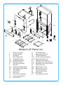
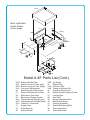
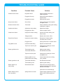
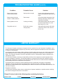
Fine Cooking Equipment For Over 70 Years
Installation,
Operation &
Maintenance
Instructions
MODEL A-4F OVER/UNDER BROILER
For Your Safety
Warning!
Do NOT store or use gasoline or
other flammable vapors and liquids
in the vicinity of this, or any other
appliance.
Improper installation, adjustment, alteration, service or
maintenance can cause property damage, injury or death.
Read the installation, operation and maintenance
instructions thoroughly before installing or servicing this
equipment.
To Purchaser
After installation of your broiler, immediately contact your local gas supplier to obtain
information in the event the user of your equipment smells gas. This information must be
posted in a prominent location.
To User
RETAIN THIS MANUAL FOR FUTURE USE
Upon receipt of this broiler, inspect it thoroughly for any damage which may have occurred during
shipment. If damage is observed, contact the delivery agency immediately.
1. Preparation For Installation: Safe and satisfactory operation of the broiler depends, to a great extent,
upon it’s proper installation. It should be installed in accordance with the National Fuel Gas Code
Z223.1, these instructions, and applicable State and Local Codes.
Installation must be made by a licensed plumber.
Initial setup must be made by a licensed service company.
A gas pressure regulator is supplied with your broiler. The regulator must be installed before connecting
broiler to gas supply line. Please note: air vent can plug with grease, thereby shutting gas supply off.
Install regulator in a drip-free area.
The broiler and it’s individual shutoff valve must be disconnected from the gas supply piping system
during any pressure testing of that system at test pressures in excess of 1/2 psig (3.45 kPa).
The Connerton Company
1131 E. Wakeham Avenue, Santa Ana, CA 92705-4145
Telephone: (714) 547-9218 Fax: (714) 547-1969
www.connertoncompany.com
Ceramic radiants are boxed and placed in grease pan for shipment. Remove top griddle plate and
carefully place them over top burners like a saddle.
2. Clearances And Ventilation: This appliance is design certified for installation on combustible floors and
adjacent to combustible walls. Minimum clearance from combustible construction; 6 inches from side
and 6 inches from back. 0 inch clearance sides and back for non-combustable locations.
Keep broiler area free and clear from combustibles.
The area in front of, and above the broiler must be clear to avoid obstruction of flow of combustion and
ventilation air. Means must be provided for adequate air supply and adequate clearance for air openings
into the combustion chamber.
Adequate clearances must be provided in front and sides of the broiler for servicing and proper
operation.
It is important that the broiler be installed under an exhaust hood which is adequate to remove the
products of combustion and cooking vapors. Sufficient make-up air must also be provided to the space
where the broiler is located to replace air removed through the exhaust hood.
3. Gas Piping: Make sure the gas pressure regulator supplied with the broiler is installed correctly, with the
arrow pointing toward the broiler. Connect outlet side of regulator to broiler. The regulator is set at 4 inch
w.c. on natural gas and 11 inch w.c. on propane gas. A 1/8” pressure tap is provided on the gas
manifold at the front of the broiler for checking the gas pressure. Please note: air vent on regulator can
plug with grease, thereby shutting gas supply off. Install regulator in drip-free area.
Connect broiler to the gas supply line. Under no circumstances should the gas supply line be smaller
than the inlet pipe on the broiler. A gas shutoff valve must be installed in the gas supply line upstream of
the broiler for complete shutdown and service. Use pipe sealant on all pipe joints. Sealant must be
resistant to the action of L.P. gasses.
For proper performance, the broiler must be level. Adjusting feet are provided at the bottom of the legs.
Carefully level the broiler using “bubble” type level on top plate.
If the broiler is supplied with casters, the installation must be made with a connector that complies with
the Standard for Connectors For Moveable Gas Appliances ANSI Z21.69, and a quick-disconnect device
that complies with the Standard For Quick-Disconnect Devices For Use With Gas Fuel ANSI Z21.41.
Adequate means must be provided to limit the movement of the broiler without depending on the
connector and the quick-disconnect device or it’s associated piping to limit the broiler movement.
Restraining device should be connected to legs or back of body.
IMPORTANT: Check all gas connections for leaks, using a soap and water solution.
DO NOT USE AN OPEN FLAME FOR CHECKING PURPOSES
4. Lighting And Relighting Of Broiler:
A. Turn gas valve and thermostat knob(s) located at the front of the broiler to “OFF”. Wait 5 minutes.
B. Turn valve knobs marked lower to “ON”. Note: thermostat remains “OFF”.
C. Turn pilot lighter valve adjusting screw(s) counterclockwise and light pilots. Adjust flame height to
approximately ¼”.
D. To light top burners, turn valve knobs marked upper to “ON”. To light bottom burners, turn
thermostats to desired temperature.
E. For complete shutdown, turn all gas valve knob(s) to “OFF” and turn pilot adjustment screw(s)
clockwise to shut off all gas supply to pilot light(s).
F. To relight, repeat above procedures.
5. Care And Maintenance:
Contact Factory, factory representative, or a local service company to perform maintenance and repairs.
Please Note: Contact Factory before any warranty repairs are made.
Operator Notes:
1. Flexible Gas Line: To prolong the life, it is important that the flexible gas line is not twisted or bent
while installing same. Carefully follow instructions, using two wrenches. Also, do not operate broiler with
the inner track pulled out, as this will cause excessive wear and breakage of the flexible gas line.
2. Roller Bearings: Lubricate rollers every other day. To prolong life, once a year the entire mechanism
should be disassembled and all bushings be cleaned and re-greased.
3. Thermostat: The thermostats can go out of calibration and should be checked periodically with a
surface thermometer.
4. Pressure Regulator: If there is no gas, the pressure regulator is possibly frozen closed, or the vent is
plugged. (Refer to section on preventative maintenance.) If this does not free the diaphragm and allow
the gas to flow through, the pressure regulator must be replaced.
5. Cleaning:
(See section on preventative maintenance for detailed cleaning procedures.)
A. To clean griddle plates, place a small amount of water on griddle while hot with long-handled
pot brush. (DO NOT USE ICE.)
B. Remove stainless steel liners for cleaning.
C. Lift out grease chute from inside to clean.
D. Periodically (but not sooner than every 3 months) clean broiler burner ports and orifices. (Note:
Make sure equipment is cold before removing.)
E. Empty grease pan and clean broiler drawer. Follow these instructions to remove broiler drawer.
1. Disconnect flexible gas connector from thermostat. Carefully hold inside hex nut with
wrench to avoid any bending or torquing of flexible line.
2. Remove front bolt from bar on inner track that assembly rolls on.
3. Pull inner track out to rear stop bolt.
4. Lift off broiling griddle from drawer.
5. Lift out broiler drawer through slots cut in inner track.
6. Clean and replace in reverse order. Grease track with high-temp grease.
6. Cooking:
1. This is a broiler/griddle combination unit. The heat from the bottom broiler burners combined with
the radiated heat from the top burners cook the product simultaneously from the top and bottom
while the broiler drawer is in the “up-and-in” position for red meat, lower for chicken, fish and pork.
2. The broiler griddle/drawer moves in and out easily on heavy duty roller bearings for loading and
unloading. It is spring balanced for easy movement up and down; automatically stays in chosen
position
3. For optimal griddle operation, turn on griddle 30 minutes prior to use.
4. Set the top burner flame at 1/2 throttle using both the left and right side manual control knobs. Set
higher if radiants do not glow red.
5. Ensure that the flames are blue in color. (Slight orange flickering is normal, but yellow flame
indicates improper gas combustion. Yellow tips on blue flames are considered acceptable.)
6. Put the bottom grill plate in the down-and-in position, and set the thermostat control knob to 350º.
7. When not cooking, the drawers must be kept in the down position. It is very important to keep the
temperature of the bottom grill plate below 450º. If the drawer is in the up-and-in position while idle,
the grill surface can reach 650º, creating hot spots as well as producing a tough meat product.
8. When turning the bottom grills on or off, use the thermostat control knob. The lower control valves
are used only for complete gas shut-off. The top burner heat temperature is controlled by the left
and right control valve knobs.
Installing Radiants:
1. Carefully remove radiant from it’s shipping
container. Radiants are made from ceramic
material and are easily chipped or broken.
2. Position radiant over top burner, lower radiant onto
burner, aligning holes in the top of the radiant with
the tabs extending from the burner.
3. Check radiant to make sure that it is centered and
resting on top of the burner, held in position by the
tabs on the burner.
NOTE: DO NOT FORCE RADIANT ONTO BURNER.
This will cause the radiant to break. If the radiant
does NOT fit gently onto burner, contact the
Factory or your factory representative.
Installing Bottom Griddle Plate:
1. Position bottom griddle plate onto drawer frame
with grease chute facing rear of broiler.
PREVENTATIVE MAINTENANCE
Overview:
Daily:
Grease chute must be kept clear and clean.
Clean griddle surfaces with grill screens and/or 3M-type coarse blending or cleaning pad.
Remove stainless steel side and back liners, clean and replace.
Drain and clean the grease pan.
Weekly:
Check thermostat calibration with surface thermometer. Contact local service company for calibration, if
necessary.
Monthly:
Disassemble grill, clean and reassemble the following parts:
Top lighter tubes
Flexible gas connector (inside grill)
Bottom drawer (remove from grill)
Griddles (top and bottom)
Inner track
Drip Spout
- Check leveling rods.
- Check drawer level (1/16” - 1/8” down in back)
- Check spring tension on bottom drawer - grill should easily return to ‘up’ position.
- Check detent assemblies - listen for ‘clicking’ sound as detent ball engages at each stop position as
drawer is moved up or down.
Daily Preventative Maintenance:
Grill screens and 3M-type cleaning pads are the only recommended method of cleaning the grills. With
repeated use they will smooth the surface of the grill, making cleaning easier.
Grill bricks are NOT recommended for use on the grills as they give a rough grill surface which causes
faster carbon buildup, resulting in the product sticking to the grill surface. The black residue from the grill
bricks is also transferred to the product, thus compromising quality.
Do not use corrosive cleaning agents on the grill. They may appear to work well on the top of the grill
surfaces, but they also destroy the interior walls of the grill, including the brackets that hold the shields and
chutes in place. Use mild to moderate degreasers only.
Cleaning the Grill: Use the following instructions for cleaning the grill:
1. Turn off grills and wait 15 minutes before cleaning.
2. Wet the grill surface with a small amount of water, or properly diluted soap solution if necessary.
Scrub the grill surface with a grill screen and/or grill pad using a left-to-right motion, to remove
almost all of the carbon buildup. NOTE: Never use ice on the grill surfaces as it will cause the grill
plate to warp. Clean lower grill in down and out position.
3. Wipe the grill surface with a towel.
4. Take a second DRY grill screen and scrub the grill surface again. This dry grill screen procedure
removes any remaining carbon buildup and polishes the grill surface.
5. Using a sharp-edged scraper, scrape any carbon buildup from the side and back walls that surround
the grill surface.
6. If available, wash the interior cavity of the grill using a hot water hose (Do not use water on the inside
when the grill is hot). Do not use the spray nozzle on the hose because splashing will damage the
top burner ceramic radiants.
7. Drain the drip pans, clean and replace them
8. Wash all front exterior surfaces using a diluted soap solution. Rinse with water and let dry.
Monthly Preventative Maintenance:
Checking Leveling Rods:
There are two leveling rods that adjust each lower griddle plate. Each rod has two adjusting nuts at the
top end, just behind the face plate of the bottom grill.
The lower nut adjusts the pitch of the back of the grill, and the upper nut tightens to secure the firm
tension of the leveling rod. The rods must NOT be lose.
Checking the lower grill plates:
To check the lower grill plates, use the following steps:
1. Put the bottom grill in the up-and-in position.
2. Mark the level of the bottom grill at the front.
3. Pull the bottom grill out and mark the level of the grill at the back.
The difference between the two marks should not exceed 1/8”. If the difference is not within this range,
adjust the leveling rods as described above.
Checking the Spring Tension of the Bottom Grills:
The spring tension regulates the ability of the drawer mechanism to lift the weight of the bottom griddle
plate. Difficulty of upwards movement indicates that spring tension must be increased. Difficulty of
downward movement indicates spring tension must be reduced.
To increase spring tension, tighten the nuts at the end of the threaded ‘J’ hook at the end of the spring,
thus extending the spring and increasing spring tension. To decrease spring tension, loosen the nuts.
NOTE: Make equal adjustments to BOTH springs to prevent unbalanced tension.
Checking the Detent Assembly:
The detent assembly regulates the full down and in-between settings before full up position is reached.
There is one detent assembly on each side of the mechanism support arms. Each assembly consists of
a steel ball bearing, spring, retaining bolt and lockdown nut. Check to insure that the depressions in the
detent plate are clean and free of deposits so that the ball bearing can roll in and out.
Screwing in the bolt increases compression on the spring which in turn increases pressure on the ball
bearing. Adjust spring compression by loosening lockdown nut and tightening the retaining bolt until a
forceful ‘clicking’ is heard as the ball bearing rides in and out of the detent plate depressions. Tighten
lockdown nut when satisfactory pressure is achieved. Adjust both detent assemblies to equal
compression for best operation.
Periodic Maintenance:
Radiants:
Verify that the radiants are glowing red. If not, the grill is not being used efficiently. Check flame color
and length. Flame tips should reach the end of the edge of the radiant fingers. Replace any broken
radiant when 2 or more fingers in a row are broken or missing. NOTE: Broken fingers will lead to
plugged burner ports.
Orifices:
2 orifice caps are used for the top burner assembly, 10 orifice caps are used for the bottom burner
assembly.
The orifice caps must be kept clean. To clean the orifices, use the following guidelines:
Remove the orifices to clean them. Clean hole in orifice hood with a toothpick from the inside to the
outside, being careful not to break the toothpick off inside the orifice. If cleaned while installed on orifice
assembly, grease will be pushed into the hood and will eventually re-plug the hole. Brass is an
extremely soft metal, and a paperclip or other harder, abrasive tool can easily enlarge the orifice
diameter leading to possible hazardous conditions.
Air Shutters:
The air shutters are located at the end of the top burner manifold and the ends of the broiler burners.
They are used to regulate the air/fuel mixture.
Typical adjustment range:
Top burners: 1/2 - 3/4 open (On top burner manifolds)
Bottom burners: 3/4 open
Insufficient air (shutter not open enough) results in longer blue to yellow flame. NOTE: this is a fuelrich setting that can produce excessive carbon monoxide. Excessive air (shutter open too far)
results in sharp translucent blue flame to flame that lifts off burner ports.
Pilot Flame:
When the pilot flame burns out beyond the lighter tube (bottom griddle), reduce the flame so that the
flame is touching and slightly around the lighter tube. The adjusting screw is on the gas supply line
between the thermostat and the pilot assembly itself. The pilot adjusting valves for the top lighter tubes
are found on the main gas manifold at the base of the unit.
Top Burners:
Clean top burners using the following steps:
1. Scrub thoroughly with a wire brush.
2. Use a #49 drill (or drill sized as close as possible without over-sizing) to re-open ports to their
original size (or as close as possible). Note: Over-sizing ports will cause improper operation
resulting in poor performance of the grill.
Ceraform Fiber Board:
Ceraform is a non-asbestos fiber board. It keeps the top griddle plate from getting too hot. It can be
damaged by water and/or by scraping it across the top of the cabinet when removing or replacing the
top griddle plate.
Inner and Outer Track Assemblies:
The inner track uses a bolt to hold it in place. Remove and replace for monthly cleaning and greasing of
the track. Removal of the bolt while in use will cause the track to slide out and cause excessive wear on
both the track and the flexible gas connector. The safety bolt is to be removed ONLY for full cleaning of
the tracks and then replaced.
Gas Pressure Regulator:
If there is little or no gas in the burners, the vent hole on the regulator is possibly plugged with grease.
To prevent the vent hole from plugging, cover the regulator lightly with aluminum foil. The regulator
should be installed on the main gas line between the grill and shut-off valve. Regulator should be
placed in a location that will minimize grease exposure.
2
4
16
3
18
1
5-L
20
5-A
13
5-R
6
9-L
19-L/R
5-A
23-B
18-B
23-A
23-B
14
46
15
22-A
9-R
7
11
10
24
45
45-A
12
21-R
21-S
22
Model A-4F Parts List
1
2
3
4
5-L
5-R
5-A
6
7
9-L
9-R
10
11
12
13
14
15
Grease Drip Spout
Ceramic Radiant
Top Burner
Back Support Bar
Top Manifold (Left)
Top Manifold (Right)
Manifold Air Mixer
Top Orifice Assembly
Valve Bar
Gas Supply Tubing (Left)
Gas Supply Tubing (Right)
Track Support
Outer Track
Inner Track
Gas Pressure Regulator
Primary Gas Manifold
Control Panel
16
17
18
18-B
19-L/R
20
21-R
21-S
22
23-A
23-B
24
45
45-A
46
Top Griddle Platel
Removable Back Liner
Top Pilot Assembly
Top Pilot Tubing Complete
Removable Side Liner
Flexible Gas Connector
Adjustable Foot Insert (Round)
Adjustable Foot Insert (Square)
Grease Drip Pan
Manual Valve (1/4 p)
Manual Valve (1/2 cc)
Chrome Valve Knob
Pop-in Swivel Caster
Stud Caster
Pilot Adjustment Valve
8-L/R
Note: right-hand
broiler drawer
mirror image
25-A
33
26
33-B
25-L/R
36
34
27
35
34-B
30-A
28
30-L/R
29
49
48
38
39
40
32
41
37
42
31
Model A-4F Parts List (Cont.)
8-L/R
25-L
25-R
25-A
26
27
28
29
30-L
30-R
30-A
31
32
33
Bottom Griddle Plate
Bottom Carryover Tube (Left)
Bottom Carryover Tube (Right)
Carryover Tube Bracket
Bottom Burner Orifice Hood
Bottom Manifold with Orifices
Mechanism Trim Panel
Mechanism Drawer Handle
Thermostat with Fittings (Left)
Thermostat with Fittings (Right)
Tubing for Thermostat
Support Arm
Roller Bearing
Bottom Burner
33-B
34
34-A
34-B
35
36
37
38
39
40
41
42
48
49
Air Shutter
Bottom Pilot
Orifice for Pilot
Tubing for Bottom Pilot
Carryover Tube Orifice
Bottom Griddle Support Frame
Leveling Rod
Axis Shaft
Spring Adjustment Rod
Mechanism Spring
Carriage Assembly
Detent (Ball/Spring/Bolt)
Thermostat Knob
Thermostat Bezel
FLEXIBLE GAS CONNECTOR INSTRUCTIONS
To prolong the life of your flexible gas connector, it is important that the
following instructions be precisely adhered to.
The connector is provided with hex-shaped fittings on each end. Fitting ‘A’ should be held
firmly with a wrench and not allowed to turn while a second wrench is used to tighten fitting
‘B’. The threaded fasteners, ‘C’, must always be in a horizontal position, pointing to the rear
of the unit. The connector should be in a smooth U-shape with upper and lower portions
being parallel when moved in any direction.
IMPORTANT: At no time should the inner track be pulled outward from the
original position while the connector is attached.
“B”
“A”
OUTER TRACK
INNER TRACK
“B”
“C”
“A”
TROUBLESHOOTING GUIDE
Condition
Small/no burner flame
Probable Cause
Solution
Regulator failure
Unplug regulator vent hole or
replace regulator.
Plugged orifice cap
Unplug hole with toothpick or
replace orifice.
Plugged burner port
Unplug burner port(s).
No top burner flame
Gas orifices
Unplug orifice hole with toothpick
or replace orifice.
No bottom burner flame
Thermostat
Check calibration and by-pass setting;
recalibrate or replace.
Small/no pilot flame
Adjustment valve setting
Adjust flame height.
Plugged pilot orifice
Clean or replace orifice.
Improper air shutter setting
Increase air shutter setting until
flame is blue.
Enlarged orifice
Replace with correct orifice.
Improper air shutter setting
Decrease air shutter setting
until flame sits on burner.
Plugged orifice
Unplug orifice hole or replace orifice.
Insulation board failing
Replace insulation board.
Top burners set full open
Change burner setting to a lower
Thermostat by-pass
Adjust by-pass setting.
Thermostat calibration
Re-calibrate thermostat.
Top burner set full open
Change burner setting to a lower
acceptable level.
Drawer griddle is in up
position when not cooking
Lower drawer when not cooking;
out if possible.
Thermostat calibration
Re-calibrate thermostat.
Thermostat by-pass
Adjust by-pass setting.
Grease/food matter
Clean inner and outer track and
carriage assembly with a degreaser.
Remove food matter.
Yellow burner flame
Flame lifts off burner
Top griddle too hot
acceptable level.
LIMITED WARRANTY
Drawer griddle too hot
Drawer griddle too cold
Bottom drawer not
easily rolling
Clean and re-oil roller bearings.
Bottom drawer hard to
lift to up position
Spring tension too loose
Tighten spring adjustment rod until
drawer can be lifted up with one
finger.
TROUBLESHOOTING GUIDE (cont.)
Condition
Probable Cause
Solution
Bottom drawer hard to
Push to down position
Spring tension too tight
Loosen spring adjustment rod until
drawer can be pushed down with one
finger.
Bottom drawer does not
remain in middle positions
Detent setup
Clean detent plate depressions, ball
bearings and springs. Replace with
new parts if necessary.
Bottom griddle not level
Leveling rod setting
Adjust left and right side rods evenly,
top nut first then bottom nut, until
pitch drops 1/8” in rear.
Top griddle not level
Broiler has not been
setup properly.
Adjust bullet feet inserts until broiler
is level from side to side, and from
front to rear.
LIMITED WARRANTY
The Connerton Company warrants to the original user for a period of one year from date of installation, not to
exceed 18 months from date of shipment by Connerton, that the equipment manufactured is free from defects
in material or workmanship.
Our obligation under this warranty shall be limited to furnishing without charge any part of said product which,
upon examination by The Connerton Company shall prove to be defective. Parts wear is not considered a
defect. The Connerton Company will not be responsible for labor or transportation charges incidental to the
replacement of same.
The Connerton Company assumes no responsibility for failure of the equipment to operate properly due to
improper installation or operation. This warranty applies to all equipment that has been unaltered, properly
installed and maintained in accordance with national and local codes and in accordance with the installation
and operating instructions included with this equipment.
This warranty does not extend to normal maintenance items, including but not limited to, thermostatic
calibrations, air and gas adjustments and adjustments to pilot flames. Proper installation, adjustments,
calibration and initial checkout is the responsibility of the dealer, the owner-user or installer and not that of The
Connerton Company.
Exceptions to warranty:
1) Flexible gas connectors that are bent or twisted due to improper installation or operation and/or modifying
the location of fittings that the tube is connected to.
Please fill out and refer to the following when contacting the factory:
Model # A-4F
Serial#
Gas Type:
Purchase Date: