1
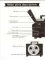
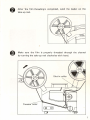
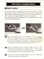
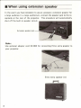
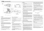
16mm
CHANNEL LOAD/Ne
~O[JfD ·.PBOJECTOB
IG-Cl/IG-CL
.
1
OPTICAL
Instruction Manual
IMPORTANT SAFEGUARDS
W hen using your photographic equipment, basic safety precautions should always be followed, including the following:
1. Read and understand all instructions.
2. Close supervision is necessary when any appliance is used
by or near children. ' Do not leave appliance unattended
while in use.
"- 3. Care must be taken as burns can occur from touching hot
parts.
4. Do not operate appliance with a damaged cord or if the
appliance has been dropped or damaged - until it has been
examined by a qualified serviceman.
5. Do not let cord hang over edge of table or counter or
touch hot surfaces.
6. If an extension cord is necessary, a cord with a suitable
current rating should be used. Cords rated for less amperage than the appliance may overheat. Care should be taken
to arrange the cord so that it will not be tripped over or
pUlled.
7. Always unplug appliance from electrical outlet when not
in use. Never yank cord to pull plug from outlet. Grasp
plug and pull to disconnect.
8. Let appliance cool completely before putting away. Store
cord in a manner provided.
9. To protect against electrical shock hazards, do not immerse
this appliance in water or other liquids.
to. To avoid electric shock hazard, do not disassemble this
appliance, but take it to a qualified serviceman when some
service or repair work is required. Incorrect reassembly
can cause electric shock hazard when the appliance is used
subsequently.
SAVE THESE INSTRUCTIONS
!
Congratulations and thank you on joining the large nation-wide
family of ELMO 16-CL sound projector owners.
You have selected a precision-engineered projector that will give
you the quality picture and sound reproduction you expected
from ELMO. However, to enjoy your ELMO projector be sure to
read this entire manual for important, helpful information.
CONTENTS
Major parts descriptions . . . . . . . . . . . . . . . . . . . . . . . . . . . .. 2
Preparation for projection ........................... 4
Film threading .................................... 6
Projection ........................................ 8
Various projections ............ ,. . . . . . . . . . . . . . . . . . . .. 9
When using extension speaker ......................... 10
Public address system ............................... 11
Rewinding ........................................ 12
Maintenance ...................................... 13
Replacing lamp and fuse ........................... . . 17
Trouble-shooting hints ....................... . ...... 20
Accessories ....................................... 22
Specifications ................................ .. ... 25
PLEASE NOTE
The instructions in this manual apply to Model 16-CL MO
(Optical/magnetic reproduction), to Model 16-CL 0 (Optical
reproduction only) and to Model 16-CL(H) (Optical/magnetic
reproducti on).
Note information as applies to specific model.
Major parts descriptions
Reel lock ------~
Take-up reel arm - - - - - - - - . . . . . :
Folding button for
take-up reel a r m - - - - - - - - - - - - - - i
Front
cover---------~
Tension roller ------------i
Tone control k n o b - - - - - - - - - Volume control k n o b - - - - - - - - - M-O switch
(Note: This switch not applicab l e to
model 16-CL - optica l on ly .)
80o-ft. take-up
reel-~
Extension speaker jack
2
~~!!!~----- Reel lock
'1-- - - - - - Feed
reel arm
:- - - - - - - - - Folding button for feed reel arm
,.-------Slot-in roller
- - - - - - Threading guide No. 1
- - - - - - Framing knob
------Scope lens holder socket
f - - - - - - - Focusing knob
- - - - - - Speaker
- - - - - - Projection lens cover
, -_ _ _ _ Threading guide No.2
f------- Master
motor, lamp, forward
& rewind control switch
: : - - - - - - - Projector elevation control
knob
!
1!.Q!i!--------Main power fuse
,.--_______ Amplifier fuse
=~~
=~
_______
Exciter lamp fuse
________ Power cord
r---------Microphone jack
3
Preparation for projection
o
Set up your projector and screen properly.
For steady projection, place the projector on a sturdy support
at right angle to the screen.
Making sure the master control power switch is at OFF, connect
the built-in power cord, which is stored in the top side receptacle
of the projector, to the AC electrical outlet.
Pull up the feed reel arm and take-up reel arm to maximum stop
position.
Turn
,
the master control
switch clockwise to a~
, which will turn the projector on forward and switch on
the lamp.
Then make adjustment for the projector and screen
positions for appropriate picture size.
pleted, turn the master
control
switch counter-
clockwise to 0 F F position.
4
through
After the set-up is com-
Install the take-up reel 240m (800ft.), which is stored on the
rear of the projector, on the rear reel spindle. The reel capacity of
the projector is max. 600m (2,OOOft.). Also install the feed reel
on the front reel spindle. At this time, be sure to set the reel in
correct position by turning down the reel locks.
Set the M-O switch in accordance with the film to be projected.
Set it to M position for magnetic sound film and 0 position
for optical sound film, respectively.
Note: Not applicable to 16-CL optical model.
Optical sound film
,0
0
0
0
~
Magnetic sound film
o
o
o
o
5
Film threading
O
Hold the tip of the film leader between thumb and index finger then pull the leader first through the slot-in roller, next over the
No.1 and No.2 rollers and finally over the tension roller.
Slot-in roller
6
Threading guide No.1
Threading guide No.2
After the film threading is completed, wind the leader on the
take-up reel.
Make sure the fi 1m is properly threaded through the channel
by turning the take-up reel clockwise with hand.
Slot- in rol ler
Tension roller
(8
7
o
Projection
Turn the master control switch clockwise to
ffJ
,then turn it
further to (]~ , and the lamp is switched on and simultaneously
the projector starts forward.
Adjust
focusing
by
turning
the
focusing knob.
If a frame I ine appears on the screen,
adjust the framing knob to left or
Framing knob
right.
Adjust the sound volume by turning the outer volume control
knob clockwise.
Adjust the sound tone by turn-ing the inner
tone control knob: Turn it clockwise or counterclockwise for
treble control.
Volume control
Tone control
Note:
If the film breaks during projection, a
safety mechanism of the projector removes the broken film from the film path
automatically_ In the event a film breaks,
t'u rn the projector to OFF and then remove the broken film for splicing.
8
Various, projections
.Quick review
This feature is used to see specific frames you wish to review. Turn the
control switch counter clock-wise from a~ all the way to ~ and the
film is quickly rewound through the gate. Then turn the control switch to
OFF, as soon as you get the desired frame for re-projection.
After making sure the film has stopped, turn the control switch from OFF
all the way to a~ through
1> .
Note:
o
When the operation switch is set t o ~ f rom 0 F F, the projector
may start rewinding onl y after a few seconds' pause depending
on the film volume on t he ree l t o be rewound.
This is not a
fault but safety mecha ni sm f o r rewinding. Th e projector is designed
to increase motor torque graduall y fo r t he protection of film .
When the operation switch is turned f rom ~ t o OF F, t he f i lm
may stop with some length of slackened loop.
I n such a case,
wind up the loose portion by turning the take-up reel clockwise
by hand and then turn the operation switch to
8
1> .
Be sure not to turn the operation switch from 0 F F to
;>
before
the film is brought to a complete stop.
9
• When using extension speaker
I n the event you have occassion to use an accessory extension speaker for
a large audience in a large auditorium, connect the speaker jack to the receptacle at the rear of the projector. This procedure will automatically
shut off the built-in speaker circuit.
Extension speaker jack
Note:
Use optional adapter cord SC-004 for connecting Elmo extra speaker to
your projector.
Elmo extra speaker (A)
10
• Public address system
You can utilize your ELMO sound projector as a public address system
during projection when an accessory microphone is inserted into the
microphone jack at the rear left side of the projector.
Use the micro-
phone with an impedance of 500 ~ 10k. Public address through a microphone during projection supercedes the sound from the projected film.
Microphone jack
• HIGH-LOW lamp switch
The switch is originally set to High position.
With the switch set to Low, a little lower voltage is applied to the
lamp to prolong the lamp service life.
When especially bright image is
required, set the switch to High to apply the rated voltage to the lamp.
(Refer to How to remove and install lamp cover, page 13.)
11
Rewinding
• When the projection is completed, rewind the film as follows.
o
I nsert the film end into
the slot of the front reel
hub.
@ Turn the operation switch
to
~.
In this case the projector
may start rewinding only
after a few seconds' pause
depending on the length of
film on the reel to b e reo
wound . The projector is d esigned to increase motor
8
torque gradually for the
protection of fi I m.
After the film is rewound, turn the operation switch to OFF .
• Stowing
o
Disconnect the power cord first.
Fold the front and rear
arms by depressing the
folding buttons.
@
Return the power cord and take-up reel to their stowing
receptacles.
8
Turn the elevation control knob fully counterclockwise.
Never transport the projector with the elevation leg extended.
12
Maintenance
Clean the film channel and lens prior to projection; accumulation of dust
and film particles in the film channel gate will scratct"l the film and decrease the projected image quality .
• How to remove and install covers
• Projection lens cover
To remove, hold the cover as shown in the picture and pull it out
toward yourself.
To install, align the guides at the lower side and
push the upper part of t he cover into place as shown in the picture.
Guide
• Front cover
To remove, hold the cover as
(,I
shown in the picture and pull
it out toward yourself.
Continued on page 14
13
To install the cover, align the framing knob with the cover notch and the
guide pins at the upper left and lower right with the corresponding holes
and push the cover into position.
(Cover shown in reverse)
Cover notch
Guide pin hole
• Cleaning film gate
Be sure to remove the film from the channel when cleaning the film
gate.
Remove the projection lens cover.
Hold the pressure plate as shown in the picture and pull it out toward
yourself, and the pressure plate can be removed.
14
Use the stiff cleaning brush (supplied) to clean film channel gate, then
wipe clean with lint-free cloth.
After the cleaning is over, align the two pins at the upper and lower
parts of the pressure plate holder with the corresponding slots on the
pressure plate base and push it back to place.
• Cleaning rollers, solar battery and sound lens
Brush off the rollers, solar battery and sound lens with the clean soft
brush supplied.
Note:
If a dust adheres to sound lens
or solar battery, the tone quality
or volume will be decreased.
15
• Cleaning projection lens
To remove the projection lens, pull it out straight while pulling the
focusing knob toward yourself.
To remove the dust, wipe the lens surface gently with soft, clean,
lint-free cloth.
Groove
To put the lens back, push it all the way to position while pulling the focusing knob toward yourself, and pull it until a click is heard . This click
sound means that the pin at the end of the focusing knob is positively inserted into the groove of the lens holder.
Make sure the lens can move back and forth by turning the focusing
knob.
16
Replacing lamp and fuse
BE SURE TO DISCONNECT THE POWER CORD WHEN
REPLACING LAMP AND FUSE .
• Replacing projection lamp
The type of projection lamp to be replaced is JCR24V-250W or
ANSI ELC or Osram 64653.
Remove the front cover.
Remove the lamp cover
by loosening the screws
cou nterclockwise.
Eject the blown lamp by
pushing down the ejector
lever to the left.
It is advisable to keep a spare projection lamp handy for immediate
replacement, should an unexpected
break or burn-out develop during
projection.
A spare projection lamp can be
stored on the back side of the front
cover.
17
To replace a new lamp, push it into the socket as shown in
the picture.
At this time, be sure to insert the lamp firmly
into its socket.
optimum
If it is inserted halfway into the socket, the
projection
performance
can't
be ·achieved or the
socket may be burned out.
Holder
_---li'-
Socket
• Replacing exciter lamp
The type of exciter lamp to be replaced is KE-04 or ANSI B R K.
o
Remove the blown exciter lamp by
turning its head counterclockwise.
To replace the new exciter lamp,
align the three prongs on the socket
with the holes on the lamp flange and
turn the lamp head clockwise until it
locks into place.
18
• Replacing fuse
To remove the fuse holders, turn the holder heads counterclockwise
with a Philips head screwdriver.
Exciter lamp fuse
Amplifier fuse
Power fuse
IMPORTANT
Use the fuse with specified value for each of the three as indicated above.
•
Check the exciter lamp fuse for blow·out when no sound is
reproduced when projecting optcial sound film. At this time, be
sure also to check the exciter lamp filament for blow-out.
•
Check the amplifier fuse for blow-out when no sound is reproduced when projecting either magnetic or optical film.
•
When the power (main) fuse is blown out, no power is supplied to
any part of the projector. Check the power (main) fuse for failure
when the projector does not operate even with the power cord
properly connected and the operation switch set to ,
19
Trouble-shooting hints
When the motor fails to operate:
• Check the power cord for proper connection.
• Check the power (main) fuse for blow-out.
When the lamp is not lit on:
• Check the lamp filament for blow-out.
• Check the lamp for proper connection with its socket.
When no sound is reproduced:
• Check the M-O switch for the correct position corresponding
to the film type used. (Not applicable to 16-CL optical)
• Check the exciter lamp if lighted (only in case of optical sound
film) .
• , Check the exciter lamp fuse for blow-out.
• Check the amplifier fuse for blow-out.
• Does a dust adhere to sound lens or solar battery?
When the image can't be properly focused:
• Check the projection lens for correct alignment, with the p in at
the rear of the focusing knob, with the groove in ! he projection
lens.
When the loop restorer operates continuously du ring p rojection:
• This
may
result
from the damaged perforat ions of several
frames, wh ich make the slack length of the film between the
two sprockets so short that no loop can be restored .
I n such
a problem, turn the operation switch to OFF and turn it again all
the way to <J ~ through
20
~
When changing the projection speed from
24 fps to 18 fps or to change electric
current cycles (50Hz - 60Hz)
• The projector is originally fixed for 24 fps. operation.
To change to 18 fps., remove the rear cover by loosening four screws
and change the projection speed as shwon in the picture .
•
Electric current cycles are adjusted at the factory for specific destined
countries.
But to change electric current cycles (50Hz ~ 60Hz)
remove the; ,rear , cover by loosening four screws and change the
belt position as indicated.
Note:
One belt
is utilized to change
electric
cycles or projection film speed.
When
belt
is used to change
electric current
cycles, the same belt cannot be used for
change of film
speed -
or vice versa.
The power cord should be detached from
electric
outlet
WITHOUT
FAI L, before
removing rear cover.
When changing voltage
When changing voltage, the power cord should be detached from
electric outlet - WITHOUT FAIL.
After removing rear cover, take out the connection wire and plug it
into the indicated voltage terminal
to be used.
There is a single voltage model
projector available to comply with
electrical regulations in specific
countries.
For this model, the
above instructions are not applicable.
21
Accessories
This lens is used for projecting
Cinemascope movies.
It can be
installed in front of the projection
lens simply by mounting it on the
accessory socket of the projector.
The projected image is horizontally
magnified twice .
• Zoom lens F1.7 f= SO
~
100mm
This wide range zoom lens eliminates the neccessity of moving projector to or from screen for desired
size of picture .
• Telephoto projection lens F1.B f= 7Smm
This telephoto lens is for projection
in a large auditorium .
• Wide-angle projection lens F1 .B 12.Smm
This is a unique super wide-angle
lens for 16mm film projection and
very effective when combined with
a
daylight
projection
device
in
schoolroom or display window etc.
22
'I
I
• Wide-angle projection lens F1.4 20mm
This wide -angle lens is designed for
projection in a small room.
This attachment lens converts the
• Conversion lens
focal length of the projection lens
to either xO.8 or x1.25, i.e., the
!
standard
50mm
lens
plus
this
accessory serves as a 40mm wideangle
lens or by reversing it a
63mm tele photo lens.
You can
make use of it when the projected
image is too small or large.
• Zoom converter
When this converter is used with
the
projection
length
from
lens,
the
focal
is conve rted con t in'uously
xO.8
to
x 1.25.
Using it,
you can vary the size of the projected image w ithou t cha ngi ng th e
projector-to-screen distance.
PROJECTION DISTANCE AND IMAGE SIZE
The projection distance refers to the dista nce between the film pla ne a nd the screen .
In meter.
In feet .
(L: Length, W: Width)
Stan dard lens
L
70
90
110
160
130
10
15
20 ~
30
40
10
15
20
30
50
0.4
0.7
1.0
1.4
2~
I
2.9
3.6
4~3
5.B
1.4
2~ I
2.9
4.3
7.2 10. 1 13 .0 15.B IB.7
7 ~7
1.9
2.9
3.B
5.B
9.6
I. B
2.7
3.6
5.4
9.0 12.6 16 .2 19 .5
7.2 12.0 16.9 2 1.7 26.5
3
---~-
e---
5
50
60
~~-
(F I.2,50mm)
IV
0 .6
0 .9
1.3
1.9
2.9
3.B
4.B
5.B
Standard lens
with Conv. lens
L
0 .5
0.9
1.2
I.B
2.7
3.6
4.5
5.4
13~5
17.4 2 1.2 25. 1
(x 0 .8)
IV
0~ 7
1.2
1.7
2.4
3.6
4.B
6.0
7 .2
2.4
3 .6
4. S
Sta nd;;ud lens
L
0.3
0~ 6
O.B
1. 1
1.7
2.3
2.9
3.4
4 .6
5 ~6
1.1
1.7
2.3
3.4
5.B
IV
0.4
0.8
1.1
1.5
2.3
3.1
3.B
4.6
6~ 2
7.5
1.5
2~3
3. 1
4.6
7.7 10.8 13.9 17 .0
1.4
2~
2.9
4.3
7.2 10 .0
13~0
15~S
3 4 ~7
4 2.4 50 .1
with Cony. lens
(x 1.25)
4 .3
5.S
I
190
B.I I DA 12.7 15.0 I S.4
20 ~
I 24 .7
I B.7
Standard le ns
L
0.4
0 ~7
9~9
1.4
2. 1
2.9
3.6
scope lens
IV
1.1
1.9
2~7
3~B
5.B
7.7
9.6
3.S
5~B
7.7 11.5 19.3 27.0
L
0 .3
0 .5
0 ~7
0 ~9
1.4
1.9
2.4
2.9
3~B
4.B
5~B
0 .9
1.4
1.9
2.9
4.B
6.7
B~6
1O~6
12.5 15 .4 I B.3
IV
0 .4
0~6
0~9
1.3
1.9
2.6
3.2
3.B
5.1
6.4
7.7
1.3
1.9
2.6
3.B
6.4
9~0
II ~6
1 4~ 1
16.7 20.6 24 .4
~
5.~
7.2 10.B IB.O
7 ~2
19.3 14.5 24 .1
wit h Elmo
Tele photo lens
(F I.B,75 mm)
Wide·angle lens
L
1.1
I.B
2.5
3.6
5.4
(F I .4,20mm)
IV
1.5
2.4
3.4
4.B
7.2
11 .5 15 .4
4.B
t--
23
• Twin extension speakers ES-1000
High performance extension speakers
with a 10" (25 cm) woofer and a tweeter. Stores conveniently in one portable case.
Rated input: 10W (Max. 15W)
16 ohms
• Carrying case with speakers
The carrying case incorporates 2 x
16.5 cm diameter dynamic speakers
and is especially useful for projection
in a large auditorium.
• Daylight projection mirror and ·Translucent screen
This accessory mirror provides a
clear projection image in a bright
area in combination with a special
translucent screen.
Two types of
screen (80 x 60 cm, 52 x 39 cm)
are available.
24
Specifications
E xciter lamp
Amplifier
MUsiqJoWer OllltPlilt
TOfle eOfltrol
Pubilfu address system
Speeifieatiofls afld desigfls are slIIbject to chaflge witholilt prior f1otice.
25
EIf1.9 ELMO CO.,LTD.
6, Kamiho-dori 1-chome, Mizuho-ku,
Nagoya, 467, JAPAN
Tel. 052-811-5131
Fax. 052-811-5142
OVERSEAS SUBSIDIARY COMPANIES
U.S.A.
Elmo Mfg. Corp.
70 New Hyde Park Road, New Hyde Park, NY 11040-9980
Tel. 516-775-3200
Fax. 516-775-3297
21720 Nordhoff Street, Chatsworth, CA 91311-5826
Tel. 818-346-4500
Fax. 818-998-4186
Canada
Elmo Canada Mfg. Corp.
44 West Drive, Brampton, Ontario, L6T 3T6
Tel. 416-453-7880
Fax. 416-453-2391
West Germany
Elmo (Europe) G.m.b.H.
Karl-Rudolf-Str. 178,4000, Dusseldorf
Tel. 0211-376051-53
Fax. 0211-376630
Printed in Japan (KO)