1
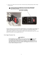
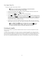
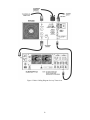
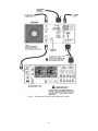
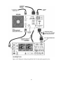
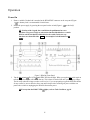
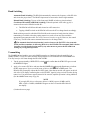
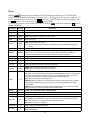
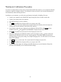
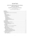
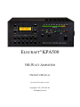
ELECRAFT KPA500 500-WATT AMPLIFIER OWNER’S MANUAL Revision D, December 24, 2013 Copyright © 2013, Elecraft, Inc. All Rights Reserved Contents Introduction............................................................................................................................................... 4 Installation ................................................................................................................................................ 5 Mains Voltage Settings ....................................................................................................................................... 6 Positioning the Amplifier .................................................................................................................................. 10 Connections to the Amplifier ............................................................................................................................ 11 Operation ................................................................................................................................................ 15 Power On ........................................................................................................................................................... 15 Band Switching ................................................................................................................................................. 16 Transmitting ...................................................................................................................................................... 16 Using ALC ........................................................................................................................................................ 17 Monitoring......................................................................................................................................................... 18 Remote Operation ............................................................................................................................................. 18 Fault Conditions ................................................................................................................................................ 19 Menu ................................................................................................................................................................. 20 Firmware Updates ............................................................................................................................................. 21 Checking your Firmware Revision ................................................................................................................... 21 Wattmeter Calibration Procedure ........................................................................................................... 22 Specifications .......................................................................................................................................... 23 Customer Service and Support ............................................................................................................... 24 Theory of Operation ............................................................................................................................... 25 AUX Connector Interface ....................................................................................................................... 26 KPA500 AUX Connector Pinout (DE-15 Male) ............................................................................................... 26 Elecraft KPAK3AUX K3 Cable ....................................................................................................................... 27 Icom Cable ........................................................................................................................................................ 27 Yaesu Cable ...................................................................................................................................................... 28 BCD Interface ......................................................................................................................................... 28 i Elecraft manuals with color images may be downloaded from www.elecraft.com. 2 WARNING Dangerous Voltages Inside the KPA500 Before opening the KPA500 enclosure: 1. Turn off the KPA500 by tapping the front panel ON switch and wait until the fan stops. (The fan drains the power supply to a safe voltage.) 2. Place the rear panel rocker switch in off (O) position and disconnect mains power from the rear panel. Key to Symbols Abbreviations and Text Styles Important – read carefully Operating tip TEMP PK HOLD Tap switch function (labeled above a switch; press for less than 1/2 second) Hold switch function (labeled below a switch; press for at least1/2 sec. to activate) LED Light Emitting Diode LCD Liquid Crystal Display CAUTION Follow the instructions under a Caution to avoid damage to the equipment. WARNING Follow the instructions under a Warning to avoid serious personal injury. 3 Introduction On behalf of our entire design team, we’d like to thank you for choosing the Elecraft KPA500 amplifier. The KPA500 offers a unique combination of features. It’s one of the smallest 500-W amplifiers available, yet it includes a built-in low-noise linear power supply based on a rugged toroidal transformer. It is capable of fully automatic operation, yet has an alphanumeric display and a full complement of front panel switches for precise manual control. A comprehensive remote-control command set is also included. The KPA500 can be used with nearly any transceiver, thanks to its instantaneous RF-based band switching, advanced protection circuitry, adjustable ALC, and extensive parametric monitoring. It also has inputs that allow direct band switching from many popular transceivers. T/R is completely noise-free thanks to the use of PIN-diode switching. Of course the KPA500 is an ideal companion for the Elecraft K3 transceiver, both physically and electrically. The K3 can sense whether the amp is in standby or operate mode, then select the appropriate per-band power settings. This allows you to set up the K3 for “barefoot” operation at one power level on each band, then switch the amp to operate and set up optimal drive levels for full 500-W output. The K3/KPA500 combination is also capable of extremely fast break-in, especially when the K3 is placed in QRQ (high-speed CW) mode. The two are so well-integrated that you can use the per-band switches on the amplifier to change bands at the transceiver. If you use the KPA500 with both the K3 transceiver and P3 panadapter – our new “K-Line” – you’ll enjoy a high degree of operating convenience, along with world-class performance and the power to get the job done. 73, Wayne, N6KR Eric, WA6HHQ 4 Installation Installation consists of the following: Installing fuses and setting the internal transformer taps according to the mains voltages used (page 5). Positioning the KPA500 to provide for proper cooling (page 10). Cabling the KPA500 to your other station equipment (page 10). The KPA500 rear panel is shown in Figure 1. The connectors and controls are described following the figure. Figure 1. KPA 500 Rear Panel SO-239 RF connector to your external antenna tuning unit (ATU), antenna or dummy load. Mains connector for the supplied power cord. ON/OFF rocker switch that controls mains power to the KPA500. Fuse block containing mains fuses. The correct fuses must be installed as described under Mains Voltage Settings on page 6. AUX connector used for connecting the KPA500 to an Elecraft K3 transceiver using the optional KPAK3AUX cable or with customer supplied cables for enhanced operation with Yaesu and Icom transceivers (see AUX Connector Interface on pg 26.) RCA type connector for PA Key input from the driving transceiver. RCA type connector for ALC to control the driving transmitter RF level. The output is negative-going from 0 VDC to -12VDC. RS232 (XVCR) connects the KPA500 to a Kenwood transceiver using a standard 9-pin serial cable. This connector cannot be used to update KPA500 firmware (see pg 21). RS232 (PC) connects the KPA500 to your personal computer with a standard 9-pin serial cable. Required for updating the KPA500 firmware. Station ground connection. A good station ground with short, direct leads connection each piece of equipment is important for consistent, reliable operation. SO-239 RF connector to the driving transceiver. 5 Mains Voltage Settings Your KPA500 is supplied with the power cable you ordered; either one using the 115VAC connector common in the USA, one with the common European (Schuko) plug for 200 VAC, or the NEMA 6-15P for 240V/15A outlets. . CAUTION Do not connect mains power to your KPA500 or attempt to turn it on before setting the fuse block switch and internal jumpers to match your supply voltage as described below; otherwise you may do extensive damage to your amplifier. Fuse Block Check to ensure the fuse block is set for either 115 VAC or 230 VAC to match your mains voltage. The current voltage setting is shown in the red window. If needed, change the fuse block setting as follows: Position the rocker switch to off (O) and disconnect the mains cord (if connected). Then open the door covering the fuse block and then carefully pry the red fuse block out of the holder as shown below: Install the proper fuses in the block. Use two 12A fuses for 115V or two 6A fuses for 230V. Use normal (fast-blow) size 3AG fuses. Both 12A and 6A fuses are supplied in marked envelopes. Note that the fuse block has a spring contact that presses one end of the fuse outward where it will rest against an electrical contact when the fuse block is reinstalled in the holder. 6 Replace the fuse block so that the correct mains voltage appears in the window in the cover. The orientation of the fuse holder sets the proper connections to the power transformer for each mains voltage range. When replacing the fuse block in the holder squeeze the fuses against the spring contact so they will slide into the holder. Be sure the fuse block is fully seated in the holder as shown below before trying to close the door. You may feel a lot of resistance just before it is fully seated as the fuses reach the contacts inside the holder. That is normal. 7 Close the cover and be sure the fuse block is oriented correctly showing the proper mains voltage as shown below: If you are setting up your just received factory-built KPA500 or a just assembled kit, the transformer tap is already set for either 116 to 126V or 231 to 250 V. Go directly to “Test the power supply voltage output” on pg 10 to determine whether you need to adjust the tap as described below. If you are reinstalling the amplifier in a new location and are unsure of the tap setting, open the top cover to verify that the correct tap is set before applying mains power. Power Supply Transformer Tap WARNING If the KPA500 has been previously turned on, tap the front panel O N switch to turn it on, and then tap it again to turn the unit off and wait for the fan to stop before removing mains power. This drains the power supply to a safe voltage. When the fan stops, remove mains power at the rear panel. (Units shipped from the factory are safe to open without turning them on first). 8 Remove the 14 screws securing the KPA500 top cover as shown below. Do not remove the screw indicated. It is part of the safety interlock switch mechanism. Lift the top cover off. Three taps are provided via red, green and yellow wires. Choose the tap according to the actual mains voltage at the outlet you plan to use for the KPA500. If you cannot measure your mains voltage, use the yellow tap. 115V Nominal Mains TAP 230V Nominal Mains 95V to 105V GREEN 190V to 210V 106V to 115V RED 211V to 230V 116V to 125V YELLOW 231V to 250V Be sure to place the unused taps side-by-side on the terminals at the back panel as shown. Do not leave them floating loose inside the unit. Replace the top cover before proceeding. An interlock switch prevents operating the amplifier with the top cover removed. 9 Power Supply Voltage Test Test the power supply voltage output as follows: The top cover must be in place on the KPA500 to activate the interlock switch before you can test the supply voltage output. Connect the mains supply cable to Position the rear-panel power switch Tap the front panel O N switch ( Tap the H V switch ( on Figure 2) and note the voltage displayed on the LCD. It must be between 65 and 85 volts. If it is outside of this range, immediately tap the O N switch to turn the KPA500 off, wait until the fan stops completely, and then position the rear panel power switch to off (O). The fan runs to discharge the power supply to a safe level. Do not disconnect mains power or position the rear panel rocker switch to off until the fan stops. Open the top cover and select a different transformer tap. If the voltage was too low, select a tap further up the list in the above table. If the voltage was too high, select a tap further down the table. on the rear panel and plug the cable into the mains outlet. to On (I). on Figure 5). The LCD should light. The red FAULT LED ( on Figure 5) will light when you tap the O N switch to protect your KPA500 if the power supply voltage is too far above the upper limit. Use a power transformer tap lower on the above table and retry the test. Positioning the Amplifier Provide at least 2 inches (5 cm) clearance behind the fan and 1 inch (2.5 cm) above the amplifier for normal cooling air flow. A clearance above the amplifier of less than 1 inch may be used when the amplifier is not subjected to highduty-cycle operation at full power (e.g. digital modes such as RTTY and PSK or contesting.) Higher duty-cycle modes will cause the amplifier temperature to increase, resulting in higher speed cooling fan operation. For those cases we recommend maintaining at least 1 inch (2.5 cm) clearance for cooling air above the amplifier. 10 Connections to the Amplifier Always turn the amplifier off using the rear panel switch ( or removing cables. in Figure 1) before attaching The KPA500 may be used with the Elecraft K3, K2 or any HF/6 meter transmitter that has a PA Key output meeting the requirements shown under note 4.below. Interconnections the transceiver are shown in Figure 2. The driving transceiver must provide up to 40 watts of RF drive for full output from the KPA500 and the driving transceiver output power must be adjustable as described under Transmitting on pg 16. The optional KPAK3AUX cable provides closer integration with the K3 by sharing band information between the KPA500 and the transceiver (see Figure 3). The KPAK3AUX cable provides all the operational features described under Operation, including coordinated band-switching (pg 16). The KPAK3AUX cable includes the PA Key line. If you need access to this line so that other equipment can control the amplifier, you can install the Key Line interrupter supplied with your KPAK3AUX cable set and use a separate key line as shown in Figure 4. You must use the Key Line Interrupter when using a separate key line with the KPAK3AUX cable set. Otherwise any external equipment inserted into the key line will not be able to inhibit the amplifier. You can make cables for use with Yaesu and Icom transceivers that also provide closer integration with the KPA500. For details of those cables and the KPAK3AUX cable set see AUX Connector Interface on page 26. 1. 2. 3. 4. NOTE Connect your station ground to the GND thumbscrew . A good station ground is important for safety and to minimize local radio frequency interference (RFI). to the output of your driving transceiver or transmitter using a 50 ohm coaxial Attach the RF INPUT cable with a PL-259 male connector on the KPA500 end. to a suitable load with an SWR of less than 1.5:1. A dummy load is strongly Attach the RF OUTPUT recommended for initial testing. The driving transmitter must ground the PA KEY line circuit during transmit while sinking up to 1 mA. If the transmitter Key Output is not a contact closure or equivalent, it must be at a level between +4 and +16 VDC during receive. (Compatible with all known transmitters. No key line buffer required.) 11 Figure 2. Basic Cabling Diagram for Any Transceiver. 12 Figure 3. K3 Enhanced Cabling Using KPAK3AUX Cable. 13 Figure 4. K3 Enhanced Cabling Using KPAK3AUX Cable and Separate Key Line. 14 Operation Power On 1. Ensure a suitable 50 ohm load is attached to the RF OUTPUT connector on the rear panel (Figure 1, ). A dummy load is recommended for initial tests. 2. Enable the power supply by pressing the rear panel rocker switch (Figure 1, position. ) to the On (I) Switches with a legend above and below the pushbutton have two functions. Tap (press briefly) to activate the function labeled above a switch. Hold to activate the function labeled below the switch. In the text, tap functions are shown like this: T E M P . An example of a hold function is P K HOLD . Figure 5. KPA500 Front Panel. 3. Tap the O N switch . The LCD and STBY LED should light. When you tap the O N switch again to turn the amplifier off you will hear the fan run. This is done to bleed off the 60V power supply voltage. The fan stops when the voltage reaches a safe level so, if you are preparing to open the KPA500 cabinet for any reason, be sure to allow the fan to run until it stops before switching off power with the rear panel rocker switch or unplugging the KPA500 from mains power. If at any time the FAULT LED lights, refer to Fault Conditions, pg. 18. 15 Band Switching Automatic Band Switching: The KPA500 automatically measures the frequency of the RF drive and selects the proper band. The PA KEY input must be connected to the driving transmitter. Manual Band Switching: Tap any of the front-panel BAND switches to select that band. Coordinated K3 and KPA500 Band Switching: When the optional AUX cable (pg 10) is connected between the KPA500 and the K3: The KPA500 will follow the band selected on a K3 transceiver. Tapping a BAND switch on the KPA500 will cause the K3 to change bands accordingly. Band switching control in which the KPA500 follows the transceiver band selection without transmitting is available with other popular transceivers such as Icom and Yaesu with the appropriate interconnection cable. See AUX Connector Interface on pg 26. However, the control is one-way. The KPA500 cannot command the transceiver to change bands. The automatic band selection function is active whenever the PA KEY is low (transmit mode) and the transmitter is delivering RF drive to the KPA500. The automatic band selection function overrides band selection made by any other means to protect the KPA500 from damage by wrong-band operation. Transmitting The POWER (W) and standing wave ratio (SWR) bargraphs are functional when the amplifier is in standby (STBY). Twenty-five watts from the driving transceiver will illuminate the first POWER LED. You may run up to 100 watts through the KPA500 in STBY. 1. Tap the operate/standby (OPER/STBY) switch the OPER LED lights. and confirm that the STBY LED goes out and 2. Apply a few watts of RF drive and note that the POWER (W) bargraph illuminates to indicate the RF output power. Never exceed 40 watts of drive to the KPA500 in OPER mode. The KPA500 will not amplify without the PA KEY signal. Note that an asterisk will appear on the left side of the LCD display confirming that a valid PA KEY signal is being received from the driving transceiver. If an underscore appears instead of the asterisk, amplifier operation is being inhibited (See the INHIBIT menu entry on pg 20) NOTE If you apply RF drive at a frequency below 1.6 MHz, between 26 MHz and 28 MHz, or above 54 MHz, INVALID will appear on the LCD and the KPA500 will not amplify. (Continued on next page) 16 3. Increase the drive power and confirm that the SWR bargraph indicates less than 1.5 while the output indicated by the POWER (W) LEDs increases. For ease in reading the critical SWR levels, the SWR LEDs are green from 1 to 1.5. The 1.5 to 2.1 SWR LEDs are yellow and the LEDs for SWRs above 2.1 are red. Up to 40 watts of drive may be required to produce the full 500 watts output from the KPA500. It is normal to hear hum from the power transformer. The hum level will increase with the power level. During heavy use, you may hear audible clicking sounds, particularly as amplifier components cool after transmitting. This is normal. it does not indicate that the amplifier is being overly stressed. NOTE The KPA500 operates to full specifications when the HV under full load is between 60V and 85V as shown on the LCD (Tap HV to display the voltage under CW “key down” conditions at full power). The maximum voltage is set using transformer taps as described on pg. 9. The KPA500 will operate with reduced performance at voltages as low as 40V. When the voltage is less than 60V the maximum output power may be less than 500W and distortion products will increase. The KPA500 will fault and automatically switch off-line if the supply voltage exceeds 90V to protect the power supply components. If your AC (Mains) line regulation is poor, such that your supply voltage is at least 85V in standby but sags below 60V during full power output, you may need to reduce the input drive to limit the power output to less than 500 watts. 4. When driving the KPA500 with an Elecraft K3, use the K3’s per-band power control to set the amplifier output just below the desired peak output on each band. Do not rely on ALC to control the power output (see Using ALC, pg 17). At the K3, set CONFIG:POWER SET to Per Band. See Per-Band Power Control in your K3 Owner’s manual for further details. If you use the AUX cable interface between the K3 and KPA500 (pg 26), the KPA500 will send the OPER/STBY status to the K3. You can then set two per-band power levels at the K3: one to drive the KPA500 when it is in OPER mode and another for pass-through transmitting when the KPA500 is in STBY. The K3 will automatically furnish your preset power levels as you switch the KPA500 between OPER and STBY. Using ALC Automatic Level Control (ALC) is a useful safety mechanism, but never use ALC as the principle power control. Doing so causes many of the unwanted transmit dynamics you often hear on the air including excessive intermodulation distortion (IMD) and clicks. Instead, set your transmitter power output correctly as described under Transmitting (pg 16) and adjust the ALC so it does not affect output power in normal operation. To do this, drive the KPA500 to the desired output. Adjust ALC THR in the menu (pg 20) until power just starts to drop and then set ALC THR above this setting so it does not affect the output power in normal operation. The Elecraft K3 ALC intentionally has a slow attack and much slower decay to avoid adding more distortion or dynamics problems than necessary. However, not all of the negative effects of ALC action can be avoided. It is still best to set the ALC threshold and then adjust the drive to avoid ALC action in normal operation. 17 Monitoring KPA500 operation is monitored by the LEDs , and and reported in text on the LCD. LEDs The SWR of the load and the output power are displayed on LED bar graphs. The bar graphs are color-coded: green for normal operating range, yellow for marginal levels and red for excessive levels. Excessive levels may trigger a fault and shut the KPA500 off (see Fault Conditions below). An LED lights if a fault condition occurs. Also two LEDs indicate whether the amplifier is in standby (STBY) or operating (OPER) mode. LCD Normally the LCD displays the band currently selected. The four switches around the LCD select other information to be displayed on the screen and the behavior of the LEDs. Note that these switches have both tap and hold functions (pg 3). Repeat the tap or hold action to return the LCD to the band display. HV displays the PA voltage on the LCD. Must be between 65 and 85 V when the KPA500 is in STBY. CURRENT TEMP displays the heat sink temperature on the LCD. Must be less than 90C. PWR displays the output power numerically on the LCD. Must not exceed 650 W. MENU EDIT displays the PA current on the LCD. Must never exceed 20 A. displays the menu system (see pg. 20). enables editing menu parameters (see pg. 20). PK HOLD toggles the peak power output display on the bar graph. When enabled, the LED corresponding to the peak power output remains lighted for one second. SWR displays the load SWR numerically on the LCD. Remote Operation The KPA500 can be controlled remotely using a personal computer connected to the RS232 port. A basic remote operating capability is built into the KPA500 Utility program (see pg 21). For those who may wish to develop their own software, a Command Reference Manual is available on the Elecraft web site. (www.elecraft.com). 18 Fault Conditions The FAULT indicator lights and the speaker sounds to indicate a fault condition has occurred. To avoid unnecessarily interrupting amplification because of moderately abnormal conditions, there are two levels of faults that may occur, attenuator faults and hard faults. Attenuator Faults Relatively minor faults such as excessive reflected power cause an internal 3dB attenuator to be switched into the RF path that reduces the output to protect the KPA500. When an attenuator fault occurs, the FAULT LED blinks and the cause is displayed on the LCD for about 1 second. The KPA500 tests the condition at intervals and will return to normal operation automatically after the cause of the fault is removed. The interval between tests is set with the ATTEN REL menu (pg 20). If the fault persists over time or if it is severe enough, a hard fault will occur. Hard Faults Hard faults are those that require switching the KPA500 to STBY to protect it, such as conditions of extremely high reflected power or high drive power, or because a critical component such as a power supply has failed. When a Hard Fault occurs, the cause of the fault is displayed on the LCD. When the condition has been corrected, tap the OP/STBY switch to return the KPA500 to normal operation, or tap the I N F O switch to return the KPA500 to STBY mode. LCD Display GAIN ERR HI CURR Fault Excessive overall amplifier gain. Excessive power amplifier current.2 HI TEMP Power amplifier temperature over limit. PWRIN HI Excessive driving power. 2 2 Fault Type Fault No.1 Hard 15 Attenuator→Hard 2 Hard 4 Attenuator→Hard 6 Hard 11 PA DISS Power amplifiers are dissipating excessive power. POUT HI Excessive power output. Attenuator→Hard 12 REFL HI Excessive reflected power (high SWR). Attenuator→Hard 9 60V HIGH 60 volt supply over limit (see Positioning the Amplifier, pg 10). Hard 8 60V FAIL 60 volt supply failure. Requires cycling KPA500 mains power after it is corrected.3 Hard 13 270V ERR 270 volt supply failure. Requires cycling KPA500 mains power after it is corrected.3 Hard 14 Communication failure between KPA500 and K3. N/A 0 N/A NOTES: 1. When the KPA500 is used with the Elecraft K3 transceiver, and the optional K3 interface cable (see Elecraft KPAK3AUX K3 Cable , pg 27) is used to connect the K3 to the KPA500, these numbers will be displayed on the K3’s LCD briefly if a hard fault occurs. 2. These faults are commonly caused by excessive power output or excessive reflected power. 3. An open KPA500 top cover interlock switch will cause this fault. See pg 9. If you have just built your KPA500 from a kit, ensure the interlock switch actuator is assembled exactly as shown under Top Cover and Side Handle in the Assembly Manual. Leaving any parts out will cause the actuator to be too short to operate the interlock switch properly. 19 Menu Holding M E N U enables the menu function to allow the following parameters to be set. With the menu function enabled, the MENU, EDIT and switches next to the and symbols all respond to a simple tap. Use them to scroll through the menu items. Tap E D I T and then the and switches to select the parameter and tap M E N U again to save the parameter. Tap M E N U to exit the menu. To reset all the parameters to the default value, press and hold the E D I T switch while tapping the O N switch to turn the KPA500 on. Menu Entry Default ALC THR 210 ATTN REL 3 Description ALC Threshold Adjustment: 0 to 210. See Using ALC on pg 17. Attenuator Release Time: 1.4 – 5 seconds. BAND CHG NOR NOR: OPER/STBY status the same after band change. STBY: Switches amp to standby after band change. DEMO NOR Factory Use Only. NOR Sets minimum fan speed. NOR: fan is off when not needed. 1 to 6: selects various minimum speeds. Fan speed increases automatically as needed for cooling. FAN CTL Displays firmware revision. FW REV ENABLE allows the amplifier operation to be inhibited (won’t amplify) when a logic low is applied to pin 11 of the AUX Connector (see pg 26). When amplification is inhibited, an underscore instead of the asterisk appears on the left end of the LCD display. INHIB IN DISABLE LCD ADJ 30 LCD Contrast Adjustment. LCD BRT 6 LCD Backlight Brightness. Use DAY in bright sunlight. 2 to 8 for indoor lighting. LED BRT 6 PWR ADJ 100 PWR ON STBY LED Brightness. Per-Band Wattmeter Calibration, range 80 to 120. These are percentages of the measured value.See Wattmeter Calibration Procedure on page 22. STBY: Amp is in standby mode when first turned on. OPER: Amp is in operate mode when first turned on. Specifies driving transceiver interface: K3: Allows use of Auxbus interface which allows the KPA500 band switches to change bands on the K3; sends KPA500 mode to the K3 so the K3 can automatically select correct drive power when the KPA500 is in OPER (see 16); reports KPA500 faults to K3. RADIO K3 BCD: Signals provided by Yaesu transceivers. ANALOG: Signals provided by Icom transceivers. Note that Icom transceivers do not identify WARC bands, but KPA500 frequency sensing will switch the KPA500 to the correct band upon transmit. SERIAL: Kenwood/Elecraft compatible interface using RS232X port. If transceiver is in split mode, the transmit frequency will select proper band at KPA500. RS232 P 38400 PC Serial Port Speed: 4800, 9600, 19200, 38400 bps RS232 X 4800 Transceiver Serial Port Speed: 4800, 9600, 19200, 38400 bps. Set RADIO to SERIAL. Displays the unit serial number. SER NUM ON: Enables KPA500 polling of the transceiver for frequency band via RS232X port (e.g. for Kenwood/Elecraft compatible interface). Note: RADIO menu entry must be set to SERIAL. SER POLL N/A OFF: Other device (PC, etc.) polls transceiver for frequency band. N/A: RADIO menu not set to SERIAL. SPEAKER TR TIME ON 0 Speaker (fault annunciator) ON or OFF. QSK Delay Time: 0 to 50 ms; Slows T/R release time for transceivers with poor transmit timing characteristics. 20 Firmware Updates From time to time updated and improved firmware may become available for the KPA500. To update firmware you will need: The KPA Utility Program available free from Elecraft at www.elecraft.com. An RS-232 cable. A computer with an RS232 port or a USB interface and a USB to RS232 converter such as the KUSB Universal Serial Bus adapter available from Elecraft. Connect your KPA500 RS232 (PC) port to your computer and launch the KPA Utility program. Use the KPA500 RS232 (PC) connector: Do not use the RS232 (XCVR) connector. Your PC must be connected directly to the RS232/PC port. You cannot ‘daisy chain’ the KPA500 with the K3 through the RS232 XCVR port. Updated firmware may be obtained in two ways. 1. Click on Firmware tab and then the Click on Copy Firmware Files from Elecraft to download the latest production released firmware or, 2. Download the new file from the Elecraft web site manually and place it in a local folder, then click on Browse… to locate the folder on your computer. This is the way to access the latest Beta firmware available from Elecraft. To install new firmware in your KPA500, click on the utility Send Firmware to the KPA500 button to start the transfer. Follow any on-screen instructions. During download the LCD will display MCU LOAD and the STBY LED will flash rapidly. The KPA500 will return to its normal power on state when the transfer is completed. Be sure to check the notes supplied with the new firmware. They may include changes that affect the instructions in this manual. If you don’t have Internet access, you can obtain a firmware upgrade on CD. If you don't have a computer, you can send your KPA500 to Elecraft to be upgraded. See Customer Service, pg.24. Checking your Firmware Revision Use the MENU entry FW Rev to determine your firmware revision. 21 Wattmeter Calibration Procedure If you have a wattmeter that you feel is more accurate than the KPA500 wattmeter, you can adjust the KPA500 wattmeter to match its readings as follows. The calibration is done per-band so you can make adjustments for individual bands without affecting the others. In addition to your wattmeter, you will need a good dummy load capable of handling 500 watts. Connect your wattmeter to the KPA500 RF Output using short, direct 50 ohm coaxial cable. Connect your dummy load to the wattmeter. Select the band that you wish to calibrate. Tap P W R on the KPA500 to display the RF power output on the LCD. Transmit briefly at 500 watts output into the external wattmeter and dummy load and compare the reading on the external wattmeter with the KPA500 wattmeter. If you wish the adjust the power displayed on the KPA500 LCD and LEDs, hold M E N U and tap switches next to the and symbols until PWR ADJ is displayed on the LCD. Hold E D I T . A number between 80 and 120 will be displayed on the LCD. If the power displayed on the KPA500 wattmeter needs to be higher, tap the switch. If the power displayed on the KPA500 needs to be lower, tap the switch. The number displayed indicates the percentage change in the power reading. For example, changing 100 to 110 will result in a 10% increase in the power indicated. Tap M E N U twice to exit the menu. The current band will be displayed on the LCD. Tap P W R on the KPA500 to display the RF power output on the LCD. Transmit again and compare the readings on the KPA500 and your external wattmeter. Repeat the procedure as needed until you are satisfied with the readings. 22 Specifications Frequency Range All Amateur Bands from 1.8 to 29.7 MHz and 50 to 54 MHz Supply Voltage and Current 100 to 125 VAC or 200 to 250 VAC, 50/60 Hz, approx. 1000 VA Weight 26 lbs (11.8 kilograms) Size Enclosure only, 4.0 x 10.8 x 10.0 in., HWD (10.2 x 27.4 x 25.4 cm). With projections, 4.4 x 10.8 x 11.8 in. (11.2 x 28.4 x 30.0 cm). The projections are the bottom feet and the fan and cable connectors on the rear. When installing, allow an additional 2” (5.1 cm) behind the fan and at least 1” (2.5 cm) above the top cover for unrestricted air flow. Power Output 500 watts PEP CW/SSB/Data Duty Cycle at 500 Watts 10 minutes key down / 5 minutes standby Drive Power 30 to 40 watts for 500 watts output Input VSWR Less than 1.5:1 ALC Out Negative-going, adjustable. Metering Power Output, SWR (bargraph and on the LCD display), supply voltage and current, temperature, frequency band. PA Current 20 A maximum PA Voltage 60 VDC, nominal Heat Sink Temperature 90°C, maximum Key In +5V maximum, open circuit on receive, closed to ground on transmit (1 mA max.) Efficiency Approximately 50% 23 Customer Service and Support Technical Assistance You can send e-mail to [email protected] and we will respond quickly – typically the same day Monday through Friday. If you need replacement parts, send an e-mail to [email protected]. Telephone assistance is available from 9 A.M. to 5 P.M. Pacific time (weekdays only) at 831-763-4211. Please use e-mail rather than calling when possible since this gives us a written record of the details of your problem and allows us to handle a larger number of requests each day. Repair / Alignment Service If necessary, you may return your Elecraft product to us for repair or alignment. (Note: We offer unlimited email and phone support, so please try that route first as we can usually help you find the problem quickly.) IMPORTANT: You must contact Elecraft before mailing your product to obtain authorization for the return, what address to ship it to and current information on repair fees and turnaround times. (Frequently we can determine the cause of your problem and save you the trouble of shipping it back to us.) Our repair location is different from our factory location in Aptos. We will give you the address to ship your kit to at the time of repair authorization. Packages shipped to Aptos without authorization will incur an additional shipping charge for reshipment from Aptos to our repair depot. Elecraft 1-Year Limited Warranty This warranty is effective as of the date of first consumer purchase (or if shipped from the factory, the date the product is shipped to the customer). It covers both our kits and fully assembled products. For kits, before requesting warranty service, you should fully complete the assembly, carefully following all instructions in the manual. Who is covered: This warranty covers the original owner of the Elecraft product as disclosed to Elecraft at the time of order. Elecraft products transferred by the purchaser to a third party, either by sale, gift, or other method, who is not disclosed to Elecraft at the time of original order, are not covered by this warranty. If the Elecraft product is being bought indirectly for a third party, the third party’s name and address must be provided at time of order to ensure warranty coverage. What is covered: During the first year after date of purchase, Elecraft will replace defective or missing parts free of charge (post-paid). We will also correct any malfunction to kits or assembled units caused by defective parts and materials. Purchaser pays inbound shipping to us for warranty repair; we pay shipping to return the repaired equipment to you by UPS ground service or equivalent to the continental USA and Canada. For Alaska, Hawaii, and other destinations outside the U.S. and Canada, actual return shipping cost is paid by the owner. What is not covered: This warranty does not cover correction of kit assembly errors. It also does not cover misalignment; repair of damage caused by misuse, negligence, or builder modifications; or any performance malfunctions involving non-Elecraft accessory equipment. The use of acid-core solder, water-soluble flux solder, or any corrosive or conductive flux or solvent will void this warranty in its entirety. Also not covered is reimbursement for loss of use, inconvenience, customer assembly or alignment time, or cost of unauthorized service. Limitation of incidental or consequential damages: This warranty does not extend to non-Elecraft equipment or components used in conjunction with our products. Any such repair or replacement is the responsibility of the customer. Elecraft will not be liable for any special, indirect, incidental or consequential damages, including but not limited to any loss of business or profits. 24 Theory of Operation When the KPA500 is in operating (OPER) mode, RF is routed by the transmit-receive (TR) switch to the power amplifier (PA) module where it is amplified by a pair of VRF2933 FETs. The PA module output is routed to the low pass filter (LPF) bank input. The LPF bank provides filters for each frequency band. The frequency of the incoming signal is monitored and the appropriate filter is automatically switched into the signal path. The filter also may be selected by band data provided by the transceiver or by front panel switches on the KPA500. However, the automatic selection based on the incoming signal frequency overrides either of those inputs to ensure the correct bandpass filter is always in the signal path. The output of the LPF bank is routed to the RF output via the TR switch. During receive or when the KPA500 is in Standby (STBY), the TR switch routes the RF input directly to the RF output, bypassing both the PA module and the low pass filter bank. The MCU in the display and control module monitors and makes critical measurements of a number of operating conditions including two levels of fault conditions that automatically alter the operation of the KPA500 (see pg 19). 25 AUX Connector Interface Do not attach a common VGA cable to the AUX connector. The AUX connector provides an optional interface that more closely integrates the KPA500 with the driving transceiver. Below are the signals available at the AUX connector. Specific cable connections for Elecraft, Icom and Yaesu equipment follow. Refer to the RADIO entry in the menu (pg 20) to enable communications via the AUX connector. KPA500 AUX Connector Pinout (DE-15 Male) Signal Name Pin Direction Notes Band VRef (Icom) 1 In AuxBus I/O 2 Out Band1 In 3 In BCD Band Input – Bit 1* NC 4 GND 5 Band V (Icom) 6 In Uses Icom standard band voltages Alarm Out 7 Out Drives low for fault input Not used by K3. Must not be connected to K3. Power On/Off 8 In Pulse low to turn KPA on or off – do not hold low! Band2 In 9 In BCD Band Input – Bit 2* Key 10 In Low enables amplification. Internally pulled up to +5V. Sources 1 mA when pulled to ground. Diode isolated from the PA KEY RCA jack. Inhibit# 11 In Low inhibits amplifier operation GND 12 Band0 In 13 In BCD Band Input – Bit 0* Band3 In 14 In BCD Band Input – Bit 3* ALC 15 Out ALC output to transceiver Reference for Icom input – connect to 8V K3 Only * See pg 28 for the BCD band codes used. Details of Aux Connector wiring cables for popular transceivers are shown on the following pages. 26 Elecraft KPAK3AUX K3 Cable This is available direct from Elecraft (pg 24): order KPAK3AUX . For the complete set: KPAK3AUX Cable, 59.5” (1.5 m) long. May be ordered separately. Order E850463. 15 pin Y cable that allows access to the K3 Aux port for other devices. May be ordered separately. Order E980190 15 pin male-female Key Line Interrupter KPAK3AUX cable wiring. Pins not shown have no connection. KPA500 AUX CONN. PIN K3 AUX CONN. PIN SIGNAL 2 2 AUXBUS 3 3 BAND 1 5 5 GND 9 9 BAND 2 10 10 PTT (See Note) 11 11 Inhibit 12 12 GND 13 13 BAND0 14 14 BAND3 15 15 ALC (Optional, see pg 17) Notes: 1. If you have devices that need access to the PTT line (e.g. some ATUs, SteppIR controllers, etc.), use the key line interrupter supplied with your KPAK3AUX cable set. The interrupter breaks the pin 10 line so you can use the separate PA Key cable (see Figure 4 on page 14). 2. Pin 4 is not used but the wire is included in the KPAK3AUX cable. Icom Cable Various models of Icom radios use either a 13-pin DIN or a 8-pin DIN connector. Be sure to use the connector that is correct for your radio. Pins not shown have no connection. KPA500 AUX CONN. PIN ICOM DIN13 CONN. PIN ICOM DIN7 CONN. PIN SIGNAL 1 1 1 8V Reference 5 2 2 Gnd 6 5 4 Band Voltage (Not CI-V) 10 3 3 HSEND 15 6 5 ALC (Optional, see pg 17) 27 Yaesu Cable Although various models of Yaesu radios use either DIN8/262 or a MiniDIN8 connector, the pin connections are the same. Pins not shown have no connection. KPA500 AUX CONN. PIN YAESU CONN. PIN SIGNAL 3 5 Bit 1 5 3&8 GND Note: Yaesu pin 8 must be grounded or TX is inhibited. 9 6 Bit 2 10 2 Key 13 4 Bit 0 14 7 Bit 3 BCD Interface The following are the band codes used by the KPA500: Band (Meters) BCD Code 60 0x0 160 0x1 80 0x2 40 0x3 30 0x4 20 0x5 17 0x6 15 0x7 12 0x8 10 0x9 6 0xA 28