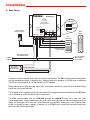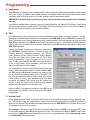
1
TECHNICAL
Practice
TELECOM SOLUTIONS
Practice
FOR THE
ES-3
Entry System
Door Controller
2 1 S T C E N T U RY
November 20, 2003
Add Up To 32 Access Entry Points
To Vikings Accessible Entry System
Up to 32 additional points of entry can be added to
Viking’s model AES-2000 Accessible Entry System.
One ES-3, one Wiegand device and a door strike or
magnetic lock of your choice is required for each additional entry point.
The ES-3 is an entry system door controller designed to
operate a door strike or magnetic lock upon receiving a
valid card read from a Wiegand device. The Wiegand
device used may be the Viking model HID-1 Proximity
Card Reader or any other card reader, RF transmitter or
digital keypad that outputs the 26 bit Wiegand format.
Up to 525 valid Wiegand codes can be programmed into the AES-2000, and up to 1024 access
entry events are logged and stored in the AES-2000. Other programmable parameters, like relay
activation and delay times, are also PC programmed via the AES-2000.
Only one pair of wires are needed to wire all 32 Entry System Door Controllers back to the AES2000. This two wire CAN communication protocol allows the ES-3 to be installed up to 1 mile
away. A door sensor input monitors for a forced door or door ajar condition. A Request to Exit input operates the
doors for people leaving the controlled area. Three separate relay outputs allow control of Door Strikes, Magnetic
Locks, Gate Opener, Lights, Camera and or Alarm. Power to the ES-3 can be daisy chained from unit to unit on
a single pair of wires, or simply tap into the local door
strike’s power supply.
Applications
Features
• Up to 525 tenants
• Up to 32 entry points are possible
• logs up to 1024 entry events
• Two wire CAN communication protocol can
be daisy-chained together
•
•
•
•
•
•
High rise apartment buildings
Condos
Senior citizen buildings
Assisted care centers
Retirement homes
Gated communities
[email protected]
• Use supplied power adapter or share with door
strike’s 12-24 Volt AC or DC power source
Specifications
• Inputs may be either normally open (NO) or
normally closed (NC) contacts
Power: Any 12-24 Volt AC or DC source @ 300mA, 12V DC
adapter included (Designed to share power with the local door
strike’s power supply)
Dimensions: 133mm x 89mm x 44mm (5.25” x 3.5” x 1.75”)
Shipping Weight: 1.3 kg (3 lbs)
Environmental: 0° C to 32° C (32° F to 90° F) with 5% to 95%
non-condensing humidity
Relay Contact Ratings: 3A @ 30V DC/250V AC maximum
Connections: 18 screw terminals
Maximum CAN Length: 0.8 Km (2600 ft) - 24 AWG twisted pair,
1.6 Km, (5300 ft) - using 2 pairs of 24 AWG twisted pair
Maximum Wiegand Length: 183 m (500 ft) - 24 AWG
• Relay outputs provide either normally open
(NO) or normally closed (NC) contacts
Phone...715.386.8861
h t t p : / / w w w. v i k i n g e l e c t r o n i c s . c o m
Wa r r a n t y
IF YOU HAVE A PROBLEM WITH A VIKING PRODUCT, PLEASE CONTACT: VIKING TECHNICAL SUPPORT AT (715) 386-8666
Our Technical Support Department is available for assistance Monday 8am - 4pm and Tuesday - Friday 8am - 5pm central time. So that we can give you better service, before you call please:
1. Know the model number, the serial number and what software version you have (see serial label).
2. Have your Technical Practice in front of you.
3. It is best if you are on site.
RETURNING PRODUCT FOR REPAIR
The following procedure is for equipment that needs repair:
1. Customer must contact Viking's Technical Support Department at 715-386-8666 to obtain a Return Authorization (RA) number. The customer MUST have a complete description of the problem, with all pertinent
information regarding the defect, such as options set, conditions, symptoms, methods to duplicate problem, frequency of failure, etc.
2. Packing: Return equipment in original box or in proper packing so that damage will not occur while in transit. Static sensitive equipment such as a circuit board should be in an anti-static bag, sandwiched between
foam and individually boxed. All equipment should be wrapped to avoid packing material lodging in or sticking to the equipment. Include ALL parts of the equipment. C.O.D. or freight collect shipments cannot be
accepted. Ship cartons prepaid to: Viking Electronics, 1531 Industrial Street, Hudson, WI 54016
3. Return shipping address: Be sure to include your return shipping address inside the box. We cannot ship to a PO Box.
4. RA number on carton: In large printing, write the R.A. number on the outside of each carton being returned.
RETURNING PRODUCT FOR EXCHANGE
The following procedure is for equipment that has failed out-of-box (within 10 days of purchase):
1. Customer must contact Viking’s Technical Support at 715-386-8666 to determine possible causes for the problem. The customer MUST be able to step through recommended tests for diagnosis.
2. If the Technical Support Product Specialist determines that the equipment is defective based on the customer's input and troubleshooting, a Return Authorization (R.A.) number will be issued. This number is valid
for fourteen (14) calendar days from the date of issue.
3. After obtaining the R.A. number, return the approved equipment to your distributor, referencing the R.A. number. Your distributor will then replace the product over the counter at no charge. The distributor will
then return the product to Viking using the same R.A. number.
4. The distributor will NOT exchange this product without first obtaining the R.A. number from you. If you haven't followed the steps listed in 1, 2 and 3, be aware that you will have to pay a
restocking charge.
WARRANTY
Viking warrants its products to be free from defects in the workmanship or materials, under normal use and service, for a period of one year from the date of purchase from any authorized Viking distributor
or 18 months from the date manufactured, which ever is greater. If at any time during the warranty period, the product is deemed defective or malfunctions, return the product to Viking Electronics, Inc., 1531
Industrial Street, Hudson, WI., 54016. Customer must contact Viking's Technical Support Department at 715-386-8666 to obtain a Return Authorization (R.A.) number.
This warranty does not cover any damage to the product due to lightning, over voltage, under voltage, accident, misuse, abuse, negligence or any damage caused by use of the product by the purchaser or
others.
Vikings sole responsibility shall be to repair or replace (at Viking's option) the material within the terms stated above. VIKING SHALL NOT BE LIABLE FOR ANY LOSS OR DAMAGE OF ANY KIND INCLUDING INCIDENTAL OR CONSEQUENTIAL DAMAGES RESULTING DIRECTLY OR INDIRECTLY FROM ANY BREACH OF ANY WARRANTY EXPRESSED OR IMPLIED, OR FOR ANY OTHER FAILURE OF
THIS PRODUCT. Some states do not allow the exclusion or limitation of incidental or consequential damages, so this limitation may not apply to you.
THIS WARRANTY IS IN LIEU OF ALL OTHER WARRANTIES, EXPRESSED OR IMPLIED, INCLUDING THE WARRANTIES OF MERCHANTABILITY AND FITNESS FOR A PARTICULAR PURPOSE,
WHICH ARE HEREBY EXCLUDED BEYOND THE ONE YEAR DURATION OF THIS WARRANTY. Some states do not allow limitation on how long an implied warranty lasts, so the above limitation may not
apply to you.
Definitions
26 bit Wiegand Format: The industry standard data output protocol of access control card readers.
CAN Communications: A highly reliable two wire communication protocol originally developed for the automotive industry.
Door is Ajar Condition: The door sensor input shows that the door remained open longer than a programmed amount of
time.
Entry Point: A door or gate allowing access into a secure or controlled area.
Facility Code: A 3-digit number that each proxy card contains in order to provide greater security. Usually the cards used
at a given building all have the same facility code. By programming cards with different facility codes, these cards can have
access to certain doors. Using this feature, the entry system can be set up for “zones”.
Forced Door Condition: The door sensor input shows that the door has opened, without the ES-3 allowing for access.
Proxy Card: A credit size card that identifies itself when within close proximity of a reader. Card “swiping” is not necessary.
The card contains a 3 digit Facility Code, a 5 digit Internal Card number and a 5 digit External Printed number, that may or
may not match the Internal number.
Proxy Card Reader: A device used to read the data from a Proxy Card when it’s held within a few inches of the reader.
Installation
A. Basic Wiring
VIKING ©
MODEL ES-3
VIKING
ELECTRONICS
HUDSON, WI 54016
Shunt
Selections
ENTRY SYSTEM
DOOR CONTROLLER
Normally
Open
Normally
Closed
ENTRY LOCATION
STATUS LED
12VDC, 500mA
Adapter (included)
INPUTS
GROUP
LO HI
POWER CAN
INPUT COMM
12-24V
AC or DC
L
H
CAN
WIEGAND
DEVICE JP6
RELAY OUTPUTS
S1
C
C
JP4
C
JP5
BLK RED GRN WHT REQUEST DOOR
WEIGAND DEVICE TO EXIT SENSOR
C
HID-2
Keypad
C
JP1
JP2
JP3
RELAY
1
RELAY
2
RELAY
3
HID-1
Card Reader
White
Green
or
Red
Black
To Wiegand Device
(not included)
CAN communications
from AES-NET board
CAN L
CAN H
and/or
HID
1
2
3
4
5
6
7
8
9
0
*
#
Up to 31 additional
ES-3 Controllers
may be added
Door Strike
Power Supply
12-24V AC or DC
Doorstrike/Magnetic Lock (not included)
A basic door access controlled entry point is wired as shown above. The ES-3 is designated to share power
with the attached door strike or magnetic lock. Voltage needs to be between 12-24 Volts with an additional
300 mA of current available or use the included 12V DC adapter.
Relays can be set as either Normally Open (NO), or Normally Closed (NC) using the shunt located directly
behind the relay screw terminals.
The Wiegand device (typically a proximity card reader) is fully supported (power and data) from the ES-3 and
can be installed up to 500 feet away using 24 gauge wire.
The ES-3 communicates with the AES-2000 through the AES-NET board via a two wire CAN
Communication Bus. CAN bus distances of up to 1/2 a mile (over 2600 feet) are achieved using common 24
gauge CAT-2 through CAT-5 wire, and 1 mile (5280 feet) is possible by doubling up on the 24 gauge twisted pair (or running at least 21 gauge). In addition, up to 32 ES-3 entry system door controllers may share
the same CAN communication pair.
B. Advanced Wiring
VIKING ©
MODEL ES-3
VIKING
ELECTRONICS
HUDSON, WI 54016
Shunt
Selections
ENTRY SYSTEM
DOOR CONTROLLER
Normally
Open
Normally
Closed
ENTRY LOCATION
STATUS LED
INPUTS
GROUP
LO HI
POWER CAN
INPUT COMM
12-24V
AC or DC
L
H
CAN
WIEGAND
DEVICE JP6
RELAY OUTPUTS
S1
C
C
JP4
C
JP5
BLK RED GRN WHT REQUEST DOOR
WEIGAND DEVICE TO EXIT SENSOR
"Push to Open"
button, push bar, switch
or motion sensor
C
C
JP1
JP2
JP3
RELAY
1
RELAY
2
RELAY
3
Alarm Panel,
Security Panel Lamp
or Camera
Magnet
Door Switch
Courtesy Lights,
Gate/DoorOpener,
Second Door Strike/
Magnetic Lock or Camera
The ES-3 can be wired with either a normally open or a normally closed Door Sensor switch by setting
the shunt located directly behind the Door Sensor screw terminals to either Normally Open (NO), or
Normally Closed (NC).
The ES-3 can be wired with either a normally open or a normally closed Request to Exit device switch by
setting the shunt located directly behind the Request to Exit screw terminals to either Normally Open
(NO), or Normally Closed (NC).
Relay 2 can provide either a Normally Open (NO), or Normally Closed (NC) contacts to control (switch
on) a courtesy light, a gate/door opener, a second door strike/magnetic lock, or start a camera. Use the
shunt located directly behind the relay screw terminals to set the normal state.
Relay 3 can provide either a Normally Open (NO), or Normally Closed (NC) contacts to trigger an alarm,
activate a security panel lamp, or start a camera. Use the shunt located directly behind the relay screw
terminals to set the normal state.
Programming
A. Assignment
Each ES-3 (up to 32 total) must be assigned with its own unique entry point location identifier. With the shunt
set to Low Group, 16 different rotary switch positions are available. After these 16 have been used, set the
remaining units to the High Group for 16 more settings using the same rotary switch.
IMPORTANT: Do NOT set group shunts and rotary switches until the entire system is wired and powered up.
If an ES-3 is installed with a duplicate entry point location identifier, the Status LED will flash. Simply move
the shunt/rotary switch to a new position. The Status LED will momentarily go off, then come on steady to
show it has its own unique entry point location identifier.
B. ES-3
Each ES-3 and all valid card numbers must be programmed in the system for proper operation. This programming is done through the telephone line interface of the AES-2000 using the PB-100 with special software. This allows either remote programming from a distant location, or local programming using the Viking
DLE-300 line simulator. The PB-100 is connected to a serial port of a P.C. and Windows based software is
used to enter relay activation times and alarm conditions for each ES-3 and the valid card numbers in the
AES-2000 data base.
Access the Remote Programmer software as described in
the AES-2000 Technical Practice. Proceed through the
"Building Selection", "Apartment Selection", and "Security
Code" screens until the "Data Transmit" screen appears.
Then click the "Entry Points" button and the "Entry Point
Quick Programming" screen will appear as shown to the
right. To start, select whether the ES-3 to be programmed is
a low or high group (shunt selectable), enter the rotary
switch position, and click "Get Status".
If a "Network Error" is given, check that the Group Shunt and
Rotary Switch assignment match an actual installed ES-3,
the ES-3 being programmed is powered up, and the CAN
bus connections are polarity correct (H & L). When all is OK,
the existing parameters such as Facility Code (see Access
Cards section C below), relay activation times and alarm
conditions will appear. New values may be entered and
applied, or click the "Guide" button to walk through detailed
programming instructions in the software itself.
After one ES-3 is programmed, select the next ES-3 to be
programmed and continue until all entry points have been
programmed.
C. Access Cards
26-bit Wiegand Access Cards, such as the HID Proximity Card, identify themselves with an eight digit number. The first three digits are considered the Facility Code and are programmed into the ES-3. The last five
digits are the Internal Card Number and are programmed into the AES-2000 as the "Keyless Entry Code"
for the person the card will be issued.
For example: If the facility code is 477 and the Internal Card Number is 00023, then program 477 as one
of the Facility Codes in each ES-3 entry point to be used. The Internal Card Number “00023” must be programmed in to AES-2000 as the Keyless Entry Code for the given apartment. (See Programming section
in the AES-2000 Technical Practice).
D. Creating Zones
Each ES-3 entry point can be programmed to accept up to 8 different Facility Codes. In this manner, different groups of users can be issued access cards with different Facility Codes to create entry points in which
some groups are allowed access, and/or other groups are not. This open form of creating “Zones” means
each Entry Point can be its own unique zone.
Note: If all Facility Codes are left set to “0”, the entry point will disregard the Facility Code all together, thus
making access entry based only on a Card Number match from the Keyless Code programmed in the AES2000.
Operation
The ES-3 Entry System Access Controller monitors the Wiegand device (ie. proximity card reader) for 26 bit
Wiegand data. When data is received, it is converted into CAN data and sent (up to 1 mile away) to the AESNET board through the shared CAN two wire pair. The AES-2000 compares the data against its programmed
data base and communicates back to the originating ES-3 whether access is granted or not. If access is granted, Relay 1 and Relay 2 will activate per their programmed delay and activation times. The Entry Point Location,
time, and Card Number will all be logged in the AES-2000. Relay 1 operates first and should be used to operate the door strike or magnetic lock. Relay 2 can be delayed from Relay 1 to operate a gate / door opener, or a
second door strike or magnetic lock for double entrance doors. Relay 2 may also be programmed with longer
times to operate courtesy lights or a camera.
If a "Push to Open" button, push bar switch, or motion sensor activates the Request to Exit input of the ES-3,
the relays will activate the same as if access is granted. No data is logged on a Request to Exit event.
If a door sensor switch is wired to the Door Sensor input of the ES-3 and the door remains open longer than the
programmed Door is Ajar timer, Relay 3 will activate for either 1 second or until the door closes (programmable). This can be used to set an alarm, light a security panel lamp, turn on a camera, etc.
If both a request to exit device and a door sensor switch are used, a Forced Door alarm condition may be selected. If the door is opened other than by the ES-3, Relay 3 will activate for either 1 second or until the door closes (programmable).
LED’s are provided for the 2 inputs and the 3 relay outputs. Each LED is located behind its associated screw
terminals. The LEDs will remain off showing the idle state, and turn on when its associated input/output is triggered/activated.
Related Products
The AES-2000 Accessible Entry System provides both audio and visual assistance for
those with disabilities.
The LCD display with large 1/2” tall characters is back-lit and will display a directory of
tenants as well as directions and prompts. A built in voice recorder and announcer can
also provide a supporting audio message. When the EZ™ Access button is pressed,
instructions on how to use the system are both displayed and announced.
AES-2000S Surface Mount
?
Need More Information on the AES-2000?
Call (715) 386-4345 and select 202.
The built in directory can support up to 525 tenant names and phone numbers and will
dial a pre-programmed phone number upon selection of a tenant. Once two-way communication has been established, the tenant can activate a remote door strike by
entering a Touch Tone command. A second relay is also provided to operate an automatic door. The AES-2000 will also support keyless entry at the door via its built-in
keypad, or by adding Wiegand-type proximity card readers, such as the Viking HID-1.
The unit is available in flush (AES-2000F) and surface mount (AES-2000S) configurations and features a highly vandal resistant housing. Note: This unit requires a PB-100 for programming.
The ES-1 is a door controller designed to operate a door strike or
magnetic lock upon receiving a valid card read and/or keyless entry
code from Wiegand devices. One ES-1, one or two Wiegand devices
and a door strike or magnetic lock of your choice is required for each
entry point.
The Wiegand device used may be the Viking model HID-1 Proximity
Card Reader and/or the Viking model HID-2 Wiegand Output Keypad
or any other card reader, RF transmitter or digital keypad that outputs
the 26 bit Wiegand format. Up to 250 valid Wiegand codes can be programmed into the ES-1.
?
Need More Information on the ES-1?
Call (715) 386-4345 and select 193.
Other programmable parameters, like relay activation, mode (normal,
off or open) and facility codes are also stored in non-volatile memory.
All programming is done with a local touch tone phone. Up to three ES-1s can be programmed simultaneously
if they will be sharing all the same programming codes and parameters. Entry logging is possible with the ES1’s log bus data output.
The HID-1 Proxy Card Reader allows proxy card entry for select Viking apartment or
office entry systems.
Using the HID-1 Proxy Card Reader instead of keyless entry codes, allows the building manager to keep control over the number of people that can let themselves into the
building. The HID-1 features standard 26-bit Wiegand interfacing and a potted enclosure with pigtail connection for indoor or outdoor applications.
The HID-1 interfaces with the AES-2000 Accessible Entry System when used with an
AES-NET Network Board. Up to 32 entry points with HID-1 Proxy Card Readers may
be added to the AES-2000.
Alternatively, the HID-1 can be used with the C-4000 Apartment/ Office Entry
Controller. Up to 4 entry points with HID-1 Proxy Card Readers may be added to each
C-4000.
?
Need More Information on the HID-1?
Call (715) 386-4345 and select 197.
The HID-2 Keypad with Wiegand output allows keyless entry for select Viking apartment or
office entry systems.
The HID-2 Keypad features standard 26-bit Wiegand interfacing, a metal enclosure with potted
electronics and a pigtail connection for indoor or outdoor applications.
The Keypad interfaces with the AES-2000 Accessible Entry System when used with an AESNET Network Board. Up to 32 entry points with HID-2 Keypads may be added to the AES-2000.
Alternatively, the HID-2 can be used with the ES-1 Stand Alone Door Entry Controller, and the
C-4000 Four Door Entry Controller.
?
Need More Information on the HID-2?
Call (715) 386-4345 and select 199.
Product Support Line...715.386.8666
Fax Back Line...715.386.4345
Due to the dynamic nature of the product design, the information contained in this document is subject to change without notice. Viking Electronics, and its affiliates and/or
subsidiaries assume no responsibility for errors and omissions contained in this information. Revisions of this document or new editions of it may be issued to incorporate
such changes.
Fax Back Doc 195
Printed in the U.S.A.
ZF301720 Rev A
8
7
6
5
4
3
2
1
8
7
6
5
4
3
2
1
Relay 3 (Alarm)
Activation Time
Door Ajar
Delay Time
Relay 2 (Doorstrike)
Activation Time
Relay 2 Delay Time
(after Relay 1 activated)
Relay 1 (Doorstrike)
Activation Time
Facility
Codes
Shunt: Hi-Group
Relay 3 (Alarm)
Activation Time
Door Ajar
Delay Time
Relay 2 (Doorstrike)
Activation Time
Relay 2 Delay Time
(after Relay 1 activated)
Relay 1 (Doorstrike)
Activation Time
Facility
Codes
Shunt: Lo-Group
0
0
1
1
2
2
3
3
4
4
5
5
6
6
7
7
8
8
Please use these charts to record the numbers programmed for the ES-3 (use pencil).
9
9
A
A
B
B
C
C
D
D
E
E
F
F