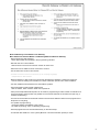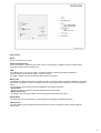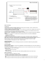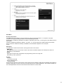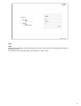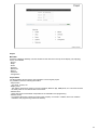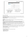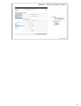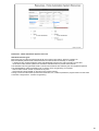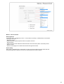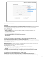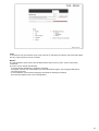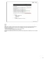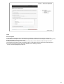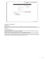
1
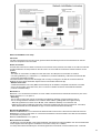
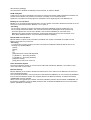
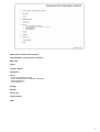
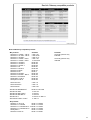
BeoLink Gateway
Type 1703
Installation Guide
Ver. 1.0 Contents
Page
BeoLink Gateway
BeoLink Gateway vs Master Link Gateway
Features
Sockett panel
Technical specifications
Basic functionality
Master Link setup
Network Link setup
Network Link / Master Link setup
Supported Home Automation Systems
BeoLink Gateway compatible products
LED System Status / Setup Button
Web-based User Interface
Connecting a PC to BeoLink Gateway
1
2
3-4
5
6
7
8
9
10
11
12
13
14
15
Menus:
- Start Menu
- Login
- Project
- Setup
- Network Settings
- Date & Time Settings
- Integration Protocol Settings
- Zones
- Systems
- BeoLink / Home Automation System
- Resources
- BeoLink / Home Automation System / Virtual
- Macros
- Macros
- Resource Event / Resource Command
- Generic Resource Event / Generic Resource Command
- Interfaces
- Tools:
- Monitor
- Log
- Service Reports
- Firmware
- Configuration:
- Save Revision
- Load from file
- Download to file
- Revision History
16 - 41
16
17
18
19
20
21
22
23 - 24
25 - 27
28
29 - 30
31 - 32
33
34
35
36
37
38
39
40
41
BeoLink Gateway
BeoLink Gateway is the successor to Master Link Gateway and is a control interface between Bang &
Olufsen products in a BeoLink system (Network Link/Master Link) and one or more Home Automation Systems.
BeoLink Gateway has a Web-based User Interface and can be accessed via the Internet browser on a
computer - Google Chrome or a similar browser.
The BeoLink Gateway makes operation and control possible in both directions - from the BeoLink system to the
Home Automation System and from the Home Automation System to the BeoLink system.
The type of connection varies depending on the Home Automation system:
- via Ethernet - IP-base systems
- via USB ↔ RS232/RS485 - non-IP-based systems.
It is possible - via the Bang & Olufsen products in the BeoLink system - to have remote operation and control of
the connected Home Automation System. As BeoLink Gateway is a two-way solution it is also possible for the
Home Automation System - via buttons on the system - to control the B&O products in the BeoLink system.
1
BeoLink Gateway versus Master Link Gateway:
Main differences between Master Link Gateway MKII and BeoLink Gateway:
- New programming web interface
- More opportunities and flexibility in the programming interface.
- General rules can now be added.
- Macros does not have to be built from scratch for each zone.
- Wait times can be added for each command in a macro.
- Use of astronomic clock for timer events.
- Possible to add own drivers in the future (“Lua” scripting language).
- Independent of SW releases.
- BeoLink Gateway is able to tell (for most drivers) the difference between a switch and a dimmer.
- Can be used for creating User Interfaces in Home Automation panels and to ease installation.
- Two way feedback with selected Home Automation Systems.
- Home automation panel instead of Web panel.
- Built in HTML5, which results in better user experience.
- CSV (Comma Separated Values) files can be used for programming to make it easier to maintain and
copy from setup to setup (makes it is possible to have a basic CSV file for favourites and just copy it
into BeoLink Gateway).
- A house can be divided into areas that contains several zones. Makes it easier for the programmer to
keep track of everything.
- Live update of programming.
- Changes happens immediately in the system.
- No need for pressing “Test” or uploading programming.
- Several programmers can work simultaneously on the same setup.
- An Indicator tells whether or not a system (BeoLink or Home Automation system) is active.
2
Features
Web panel.
Connection of IP-cameras.
Home Automation menu on the TV
- Like Smart TV.
- Overview/status/control of the entire house.
- Two-way feedback form Home Automation systems.
- Set-up and control of IP cameras.
- Must be setup manually in the browser in the TV using the IP-address of BeoLink Gateway.
Network Link functionality
- Control and status from Network Link products.
- PUC control received automatically from the TV’s.
- Favourite logos for TV and Radio stations to be programmed.
Master Link functionality
- Control and limited status feedback from Master Link products.
- Browsing CD covers and control of BeoSound 5 via the Beolink App.
- Favourite logos for TV and Radio stations to be programmed.
- Operation and control of the Master Link system via and iPhone/iPad.
System setup via BeoLink App (will be implemented later)
- All general system related items such as favourites, users, zones, specialized buttons etc. are stored
in BeoLink Gateway.
3
Features
In a BeoLink setup (Network Link/Master Link) with a BeoLink Gateway and a Home Automation System
connected the following features are available:
Beo4, Beo6, BeoRemote One and BeoLink App operation
Operation of Bang & Olufsen products in a BeoLink Link system (Network Link/Master Link) with Beo4, Beo6,
BeoRemote One and the BeoLink App.
- Home Automation System operation with Beo4, Beo6, BeoRemote One - via the BeoLink system from every zone (product) in the house. BeoLink App operation is possible as well.
The functions of the Home Automation System reacting on Beo4, Beo6, BeoRemote One and BeoLink App
commands, are decided by the programming of the BeoLink Gateway.
Home Automation System operation
- Home Automation System operation of Bang & Olufsen products - via the BeoLink system - with buttons on
the Home Automation System panels.
Which of the Bang & Olufsen products reacting and how are decided by the programming of BeoLink
Gateway.
With Bang & Olufsen products and a BeoLink Gateway in a BeoLink system (Network Link/Master Link), it is
possible to control and operate the Home Automation equipment connected all over the house with a B&O
remote control.
Actions involving both the Home Automation equipment and B&O products can be combined - e.g. switching on
the light and turning on the TV in the main room, or different light scenes can be set.
A button on Beo4, Beo6 and the BeoLink App can be dedicated and named, to carry out the wanted operation
sequence.
4
Socket panel
Mains
For the connection to the mains.
Network Link (Ethernet)
For the connection to a Network Link router to have communication via Ethernet with a IP-based Home
Automation system and the Network Link.
USB
The USB sockets are for the connection of Home Automation systems with RS232 and RS 485
communication. This requires an USB ↔ RS232 converter.
The USB ↔ RS232 converter for the B&O ServiceTool can be used.
Master Link
The Master Link socket and the RJ45 socket are used to connect products connected in a Master Link system.
This makes it possible to control a compatible audio and video system and to distribute sound throughout the
house.
The connections in the RJ45 socket and the Master Link socket are identical.
- RJ 45 socket
The RJ45 socket is for Master Link cable equipped with a RJ45 socket.
- Master Link socket
The Master Link socket is for Master Link cable equipped with a Master Link plug.
Setup Button
The setup button can be used during normal operation by pressing and holding the button.
LED Indicator
The LED Indicator gives feedback about the status of the system and about functions selected with the
‘Setup button’.
5
Technical specifications
Type no:
- Type 1703
- One type only.
Mains
- 100 V~ - 240 V~ - 50 Hz/60Hz.
Power consumption
- 7.7 W
- 13 W - with USB devices connected.
Display
- Internal Web server.
Operating conditions
- Temperature: 10° C - +50° C.
- Humidity: 20% - 80%.
6
Basic funtionality
Control flow
The control flow in BeoLink Gateway is based on macros by their functionality. A macro contains a list of
‘EVENTS’ (data) and a list of ‘COMMANDS’ (data).
A macro is triggered (activated) by an ‘EVENT’, which could be an IR command from a B&O remote control or a
command from the Home Automation System.
The ‘EVENTS’ from the products on the Network Link and/or the Master Link and ‘EVENTS’ from the Home
Automation System are ‘mapped’ (listed) in BeoLink Gateway.
BeoLink Gateway ‘COMMANDS’ are also ‘mapped’. The ‘mapping’ is done during the programming of BeoLink
Gateway.
When a macro is triggered by an ‘EVENT’ BeoLink Gateway transfers the associated ‘COMMANDS’.
- ‘EVENTS’ = input data
- ‘COMMANDS’ = Output data
‘EVENTS’ are transferred to the BeoLink Gateway from products on the BeoLink system (Network Link/
Master Link) and the Home Automation System and ‘COMMANDS’ are transferred from the BeoLink Gateway to
the products on the BeoLink system (Network Link/ Master Link) and the Home Automation System.
BeoLink Gateway is able to control Home Automation Systems with RS232 connection via USB.
Connecting RS232 via USB requires an USB ↔ RS232 converter.
Identifying products
BeoLink Gateway has a function for identifying the products connected to the BeoLink system (Network
Link/Master Link).
2 x 65 commands
BeoLink Gateway is offering 2 x 65 LIGHT and CONTROL commands (‘EVENTS’) per room and the operation of
the system is very flexible.
The commands can be local or global or a combination of both. It is the command list in the macro, which decides
whether or not a command is local or global.
- Local command:
- Switching the light off in one room.
- Global command:
- Switching the light off in the entire house and/or switching off B&O products in the entire house.
BeoLink commands
IR simulated commands via the BeoLink system:
- Transmits (Tx) IR simulated commands to products on the Network Link.
- Transmits (Tx) IR simulated commands to products on the Master Link.
- Receives (Rx) IR simulated commands (LIGHT and CONTROL address) from products on the Network
Link.
- Receives (Rx) IR simulated commands (LIGHT and CONTROL address) from products on the Master
7
Link.
- Receives (Rx) status information from products on the Network Link and the Master Link. Status is passed
on by the BLGW protocol to the Home Automation System via Ethernet or USB/RS232.
Master Link setup
ISP router
The ISP (Internet Service Provider) router gives access to the Internet and is used as router for computers on the
LAN and for the BeoLink Gateway.
BeoVision 7-40
BeoVision 7-40 is the ‘video master’ in the Master Link setup and is set to option 2.
The TV is connected in the Master Link system with a Master Link cable from the Master Link socket to
a junction box.
- Rerouting
The re-routing of light and controls commands to BeoLink Gateway must be enabled in BeoVision 7-40.
The re-routing should be enabled in the ‘Customer Service Menu’ [Adjustment].
- MLGW Command:
Must always be enabled when a BeoLink Gateway is connected on the Master Link system. Enabling the
MLGW Command allows light and control commands - from Beo4/Beo6 - to be rerouted to the BeoLink
Gateway.
- MLGW Status:
Must be enabled only if the Home Automation System connected is equipped with a display. Enabling the
MLGW Status allows display information to be shown in the display on the Home Automation System
panel.
BeoSound 4
BeoSound 4 is the ‘audio master’ in the Master Link setup and is in option 0.
BeoSound 4 is connected in the Master Link system with a Master Link cable from the Master Link socket to a
junction box.
BeoSound 4 is only able to work with the Home Automation System because it is connected via a ‘master’
(BeoVision 7-40 ) when it is in option 0. BeoSound 4 In option 0 acts as Source Center to the TV, and audio
sources played via the TV is controlled through the TV.
BeoSound 4 in option 1 or 2 is able to work on it’s own with a Home Automation System.
Link room products
- BeoVision 7-32
BeoVision 7-32 is working as a Link Room product and is in option 6. It is connected in the Master Link
system via a Master Link cable from the Master Link socket to a junction box.
- Rerouting
The re-routing of light and controls commands to BeoLink Gateway must be enabled in BeoVison 7-32.
The re-routing should be enabled in the ‘Customer Service Menu’ [Adjustment].
- MLGW Command:
Must always be enabled when a BeoLink Gateway is connected on the Master Link system.
Enabling the MLGW Command allows light and control commands - from Beo4/Beo6 - to be rerouted to
8
the BeoLink Gateway.
- MLGW Status:
Must be enabled only if the Home Automation System connected is equipped with a display.
Enabling MLGW Status allows display information to be shown in the display on the Home Automation
System panel.
- BeoLab 3500
BeoLab 3500 is in option 6 and connected in the Master Link system via a Master Link cable from the
Master Link socket to a junction box.
- Re-routing
To activate the re-routing of light and control commands to the BLGW in BeoLab 3500 is done in the
following way with Beo4/Beo6.
- [Menu]
- [Menu]
- [0]
- [5]
- [GO] ‘BLGW off’ Current state displayed
- [∧] ‘BLGW on’ - (Rerouting enabled)
- [∨] ‘BLGW off’ - (Rerouting disabled)
- [GO] Store setting
- [Stop] Exit (or after 3 sec. time out)
Home Automation System
The Home Automation System is connected to the router to be connected to BeoLink Gateway.
BeoLink Gateway
The BeoLink Gateway is connected to the router/switch with a CAT7 cable from the Network Link socket to a
port on the router/switch and to the Master Link system via the Master Link socket.
The ‘EVENTS’ from the products on the Master Link and ‘EVENTS’ from the Home Automation System on
the Ethernet are ‘mapped’ (listed) in the BeoLink Gateway.
When a macro is triggered by an ‘EVENT’ the BeoLink Gateway transfers the associated ‘COMMANDS’ via
the Master Link to the B&O products and/or via the Ethernet to the Home Automation System. (See Basic
functionality).
Network Link setup
ISP router
The ISP (Internet Service Provider) router gives the BeoLink Gateway access to the Internet and is used as
router for computers on the local LAN.
Router and switch
As most ISP routers have a stable connection to the Internet and to products connected on the LAN it is sufficient
to build a Network Link setup based on the ISP router. As more LAN connections are needed a switch can be
applied.
- Switch
The switch is connected to a LAN port on the ISP router. Five LAN ports on the switch are used for
connecting two BeoPlay V1, a Beovison 11, a BeoLink Gateway and a Home Automation System.
This basic Network setup has the advantage, that it is easy to configure to be able to access the BeoLink
Gateway and the Home Automation System from an iPad with the BeoLink App.
- Network Link router.
A dedicated Network Link router (B&O recommended) can be added if a separate sub-network is needed,
due to varying quality of the ISP router, when it comes to a stable connection and distribution between
products in the B&O setup.
BeoPlay V1 and BeoVison 11
The two BeoPlay V1 and BeoVison 11 are connected to the switch via CAT7 cables connected to the
Ethernet sockets on the TV’s and ports on the switch.
BeoVision 11 and both BeoPlay V1 are in option 2.
- Rerouting
The re-routing of light and controls commands to the BeoLink Gateway must be enabled in the TVs.
The re-routing should be enabled in the ‘Customer Service Menu’ [Settings/Reroute Light/Control].
- ‘Reroute Light/Control’ must be set to ‘BLGW’, when a BeoLink Gateway is connected on the Network
Link system. Enabling ‘Reroute Light/Control’ allows light and control commands - from Beo4, Beo6,
BeoRemote One and the BeoLink App - to be rerouted to the BeoLink Gateway.
Home Automation System
The Home Automation System is, for the communication with the BeoLink Gateway, connected to a port on the
switch with a CAT7 cable.
BeoLink Gateway
The BeoLink Gateway is connected to the switch with a CAT7 cable from the Network Link socket to a port on the
switch.
The ‘EVENTS’ from the products on the Network Link and ‘EVENTS’ from the Home Automation System are
‘mapped’ (listed) in macros in the BeoLink Gateway. The BeoLink Gateway ‘COMMANDS’ are also ‘mapped’.
When a macro is triggered by an ‘EVENT’ the BeoLink Gateway transfers the associated ‘COMMANDS’ via the
9
Network Link to the B&O products and/or via the Ethernet/RS232 to the Home Automation System. (See
Basic functionality).
Network Link/Master Link setup
ISP router
The ISP (Internet Service Provider) router gives the BeoLink Gateway access to the Internet and is used as
router for computers on the local LAN.
Router and switch
As most ISP routers have a stable connection to the Internet and to products connected on the LAN it is sufficient
to build a Network Link setup based on the ISP router. As more LAN connections are needed a switch can be
applied.
- Switch
The switch is connected to a LAN port on the ISP router. Six LAN ports on the switch are used for
connecting a BeoPlay V1, a BeoVison 11, a BeoSound 5, a BeoLink Gateway, a BeoLink Converter NL/ML
and a Home Automation System.
This basic Network setup has the advantage, that it is easy to configure to be able to access the BeoLink
Gateway and the Home Automation System from an iPad with the BeoLink App.
- Network Link router.
A dedicated Network Link router (B&O recommended) can be added if a separate sub-network is needed,
due to varying quality of the ISP router, when it comes to a stable connection and distribution between
products in the B&O setup.
BeoVision 11
BeoVision 11 is connected to the switch via CAT7 cables connected from the Ethernet sockets to a port on the
switch. BeoVision 11 is in option 2.
- Rerouting
The re-routing of light and controls commands to the BeoLink Gateway must be enabled in the TV.
The re-routing should be enabled in the ‘Customer Service Menu’ [Settings/Re-route Light/Control].
- ‘Reroute Light/Control’ must be set to ‘BLGW’, when a BeoLink Gateway is connected on the
Network Link system. Enabling the Reroute Light/Control allows light and control commands - from Beo4,
Beo6, BeoRemote One and the BeoLink App - to be rerouted to the BeoLink Gateway.
BeoSound 5/BeoMaster 5
BeoSound 5/BeoMaster 5 is connected to the Ethernet switch with a CAT7 cable from the Ethernet socket on
BeoMaster 5 to a port on the switch. Is connected to the Master Link with a Master Link cable from the Master
Link socket to a junction box.
BeoSound 5/BeoMaster 5 is in option 0.
BeoLink Converter NL/ML
The BeoLink Converter NL/ML is the interface between the Network Link and the Master Link and it handles both
control signals and audio signals. The BeoLink Converter is setup as a V.Master.
In a setup with a BeoLink Gateway the ‘Forward Light/Control commands’ must be enabled in the ‘‘Customer
10
Service Menu’ [Settings].
The hostname for the BeoLink Gateway must be entered, for instance ‘BLGW’.
NL/ML Delay Box
A delay box is mounted in the Master Link system to prevent echo-effects (delay) between the Network Link
product and the Master Link products in Link Room. The delay occur because the audio
signals are converted from analog signals on the Master Link to digital signals on the Network Link.
BeoPlay V1 in a Link Room
BeoPlay V1 is connected to the Ethernet switch via CAT7 cables connected to the Ethernet socket on the TV
and a port on the Ethernet switch. BeoPlay V1 is in option 2.
- Rerouting
The re-routing of light and controls commands to the BeoLink Gateway must be enabled in the TV.
The re-routing should be enabled in the ‘Customer Service Menu’ [Settings/Re-route Light/Control].
- ‘Reroute Light/Control’ must be set to ‘BLGW’, when a BeoLink Gateway is connected on the
Network Link system. Enabling the Reroute Light/Control allows light and control commands - from
Beo4, Beo6, BeoRemote One - to be rerouted to the BeoLink Gateway.
BeoLab 3500 in a Link Room
BeoLab 3500 is in option 6 and connected in the Master Link system via a Master Link cable from the
Master Link socket to a junction box.
- Re-routing
To activate the re-routing of light and control commands to the BLGW in BeoLab 3500 is done in the
following way with Beo4/Beo6.
- [Menu]
- [Menu]
- [0]
- [5]
- [GO] ‘BLGW off’ Current state displayed
- [∧] ‘BLGW on’ - (Rerouting enabled)
- [∨] ‘BLGW off’ - (Rerouting disabled)
- [GO] Store setting
- [Stop] Exit (or after 3 sec. time out)
Home Automation System
The home Automation System is, for the communication with the BeoLink Gateway, connected to a port
on the switch with a CAT7 cable.
BeoLink Gateway
BeoLink Gateway is connected to the Ethernet switch with a CAT7 cable from the Network Link socket to a
port on the Ethernet switch.
The commands (‘EVENTS’), from the products on the Network Link/Master Link, and commands (‘EVENTS’)
from the Home Automation System are ‘mapped’ (listed) in the BeoLink Gateway. The BeoLink Gateway
‘COMMANDS’ are also ‘mapped’.
When a macro is triggered by an ‘EVENT’ the BeoLink Gateway transfers the associated ‘COMMANDS’ via
the Network Link/Master Link to the B&O products and/or via the Ethernet/RS232 to the Home Automation
System. (See Basic functionality).
Supported Home Automation Systems
Lauritz Knudsen, IHC-Schneider, LexControl
KNX - EIB
Clipsal
Legrand - Bticino
SmartHouse
Lutron
- Lutron HomeWorks Interactive
- Lutron Homeworks QS - Radio Ra2 - Grafik QS
- Lutron Graphic Eye
- Lutron Radio Ra
Vantage
Dynalite
Conson XP
Custom Strings
Velux
11
BeoLink Gateway compatible products
- ML products
- BeoVision 7-32 MK I - MK IV
- BeoVision 7-32 MK I - MK IV
- BeoVision 7-32 MK V
- BeoVision 7-40 MK I / MK II
- BeoVision 7-40 MK I / MK II
- BeoVision 7-40 MK III
- BeoVision 7-40 MK IV
- BeoVision 7-40 MK V
- BeoVison 7-55
- BeoVison 7-55 MK II
- BeoVision 8-26/32
- BeoVision 8-40
- BeoVision 8-40 MK II
- BeoVision 9-50 MK I - MK III
- BeoVison 10-32/40/46
- BeoSystem 3 / MK II
- Beosystem 3 MK III
Software
≥ SW 7.94
≥ SW 30.08
≥ SW 10.11
≥ SW 7.94
≥ SW 30.08
Build 433
Build 524
Build 632
Build 551
Build 956
Build 137
Build 77
Build 109
Build 433
Build 165
Build 433
Build 933
- BeoLink Active
- BeoLink Passive
- BeoLab 3500
≥ SW 1.6
≥ SW 1.6
≥ SW 3.30
- BeoSound 5/BeoMaster5*
- BeoSound 3200*
- BeoSound 9000 / MK II*
- BeoSound 9000 MK III*
- BeoSound 4*
- BeoCenter 2 MK II / Audio*
Build 6.0.2.00.1902
≥ SW 1.94
≥ SW 2.21
≥ SW 3.42
≥ SW 32.15 / SW 2.5
≥ SW 5.9
- NL products
- BeoPlay V1-32/ V-40
- BeoVision 11-40/46/55
- BeoVision 11-40/46/55 MK II - III
- BeoVision 11-40/46/55 MK IV
- BeoSystem 4
- BeoVision Avant-55
Build 1.0.3.30552
Build 1.0.4.31549
Build 1.0.5.33043
Build 1.0.5.34322
Build 1.0.4.31549
Build 1.0.6.35397
Remarks
HD-ready products only
DVB-HD
HD-ready products only
DVB-HD
12
*As the audio products are ML audio masters they can be used alone with BeoLink Gateway.
All Audio Masters are able to receive commands from BLGW, no matter which option they are in.
In a integrated setup (option 0) the commands must be send to the Video Master using the audio master as
source center.
Note!
For further information about SW versions and compatibility follow the link:
https://retail.bang-olufsen.dk/beowise/BeoWise_UK.nsf/DocName/Tip.MLGateway.17981799.RSKA7PDANF
LED System Status
BeoLink Gateway is equipped with an LED indicator, which is used to display the system status of BeoLink
Gateway. The LED, placed at the lower part of the connection panel, is also used to give feedback when the
Setup button is operated.
LED Indicator
Solid green
Quickly - green/red loop
Solid red
Flashing green - slowly
Flashing red - slowly
- Normal operation
- Critical error
- H8 / FEP or FPGA upgrade
- Software upgrade / System boot
- Master Link synchronization
Setup Button functions
The Setup button, providing several functions during normal operation, is placed at the lower part of the
connection panel.
Function 1: System event
- Executing macros with EVENT.
Function 2: Reset password to default
- ‘Password’ to factory default (admin).
Function 3: Fixed IP-address
- Enables the default IP-address (192.168.1.10).
Function 4: Factory default
- Erases all configuration and settings.
Function 5:
Function 6: Dynamic IP-address
- Enables DHCP - dynamic IP-address.
Select a function
Press and hold the setup button and the system will cycle through the functions. The LED indicator lights red and
indicates the function number by flashing - function no 1 = one flash, function no 2 = two flashes,
3 = flashes,etc.
When the desired function is reached the button should be released and the LED indicator starts to flash red.
To confirm the function execution the setup button should pressed again within 3 seconds.
13
Web-based User Interface
BeoLink Gateway contains a web-based User Interface - as in a router. This means that the user interface can be
accessed by using the Internet browser on the PC. All configuration of BeoLink Gateway is done by means of the
web-based User Interface.
The browser must be, for instance Google Chrome, IE 10, Safari with Bonjour or a similar browser.
Navigation
The User Interface contains different menus, which can be selected in a navigation bar. It is recommended not to
use the back and forward navigation buttons in the browser because information entered may be lost.
Save settings
Auto saving at least every 20th minute if there is a low or no programming activity. At a higher programming
activity auto saving will be performed with shorter intervals.
The ‘Save’, 'Add' or ‘Apply’ buttons in a specific menu should always be used, before leaving the menu, as
changing to another menu will not save the settings made.
Help function
The Help function, which contains all help items can be accessed with the ‘Help’ button and a ‘Table of Contents’
button.
All menus in the web-based User Interface have a link to the Help-function. When the link is activated the current
window with the menu is replaced and the relevant part of the help function is shown.
To avoid the window with the menu to be replaced right-click on ‘Help’ and select ‘Open another tab’.
14
Connecting a PC to BeoLink Gateway
Basic connections
As the BeoLink Gateway contains a web-based user interface a PC must be connected to be able to access the
user interface. The user interface is used to setup and configure BeoLink Gateway.
The PC and BeoLink Gateway can be connected in two ways:
- BeoLink Gateway connected to a LAN.
If a router is available it is recommended to connect the BeoLink Gateway and the PC via the router. This
makes it possible to update the BeoLink Gateway automatically via the Internet.
- The PC directly to BeoLink Gateway.
BeoLink Gateway can - for initial setup and SW update - be connected directly to a PC with an Ethernet
cable from the Network Link socket to the network port on the PC. It can be necessary - depending on the
PC - to use a ‘cross-over’ Ethernet cable.
To use ‘direct’ Ethernet cable the BLGW must be setup with a static IP-address.
Note!
DHCP is default enabled from the factory.
If a fixed IP-address is selected the default IP-address of BeoLink Gateway is 192.168.1.10
Depending on the actual network settings it may be necessary to change the IP-address to fit the network
range.
15
Start Menu
Access to the menus
The WEB-based user interface can be accessed by using the Internet browser on a computer. The latest
browser’s are supported. Bang & Olufsen recommends Google Chrome.
As the DHCP is enabled by default the IP-address - allocated by the router - must be typed in the address field of
the browser.
If DHCP is disabled the default IP-address - 192.168.1.10 - must be typed in the address field of the browser.
When connection to BeoLink Gateway is established, the Start Menu appears on the computer
screen.
Start menu
The Start Menu contains two functions, which gives access to sub-menus.
- WEB panel
The WEB panel menu is a for remote control of the Home Automation System via mobile phone, iPad, etc.
Protected by ‘user password’.
- Setup
Setup gives access to the configuration and programming menus via a login box.
Protected by ‘admin’ password.
Access
- Computer
- Via Internet and LAN
- iPad and Mobile phone
- Via 3G and WiFi
Access from the Internet or 3G requires a router with known IP address or URL. BeoLink Gateway will publish all
relevant configuration of rooms, sources and virtual buttons to the mobile applications. This makes it possible for
the mobile applications to build a user interface which match the current setup.
16
Login
Login
To access the configuration and programming menus ‘admin’ must be entered in both fields in the login box
followed by <Enter>.
The ‘Password’ can be changed, while the ‘User Name’ is always ‘admin’.
17
Project
Menu Bar
All menus in BeoLink Gateway can be accessed via the menu bar in the top of the display. The following
menus are available:
- Project
- Setup
- Zones
- Systems
- Resources
- Macros
- Interfaces
- Configuration
Project Menu
The Project Menu can be used to give information concerning the project.
It is possible to store the following information:
- Project name
- Any name, number, etc.
- Display name
- The display name will be shown on all user interfaces, BeoLink App, WEB panel, etc. The name could be
the family name or the name/number of the house.
- Installer name
- Name of the technician/installer responsible for the installation and programming.
- Installer contact
- For instance the phone number and name of the company / technician / installer, which has made the
installation and programming of BeoLink Gateway.
18
Setup - Network settings
The Network Settings menu is used to setup the network settings to adapt to the actual network to which the
BeoLink Gateway is connected.
BeoLink Gateway is delivered with DHCP enabled from the factory, which means that the network settings are
assigned automatically.
All the network settings can be changed in the Network Settings menu.
Hostname
The name by which BeoLink Gateway is found in the LAN. The Hostname must always be a single word,
which contains capital letters, small letters or numbers.
DHCP
If the DHCP server in the router is enabled the DHCP must also be enabled in the Network Settings menu. It is
recommended to reserve an IP-address in the router or use a static IP-address if DHCP is disabled.
If the DHCP is disabled in the router, the IP-address must be entered manually in the Network Settings menu.
The settings for subnet mask, default gateway and DNS server must be set to the same settings as in the router.
Apply button
Networks settings must be applied with the Apply button. It is possible to edit the settings and check the
consistency safely, as changes will first takes place when the Apply button is activated. The settings will be saved
automatically by the ‘Auto Save’ function.
Depending on the actual network it might be necessary to change the IP-address in order to adapt to the network
in range. The other networks settings in the Network Settings menu must also - if necessary - be changed to
match the router settings.
To determine the network settings the router in the network must be accessed.
DHCP is enabled from the factory.
Default network settings with static IP-address (DHCP disabled):
- IP-address: 192.168.1.10
- Subnet mask: 255.255.255.0
- Default gateway: 192.168.1.1
- DNS server: 192.168.1.1
19
Setup - Date & Time Settings
Date & time settings
A correct time setting is important as it is used for the monitoring of events, astronomic clock events and for
time stamping the error log, for instance to show the exact time a fault has occurred.
The system will still work even if the time setting is not correct.
The date and time settings can be synchronized with Internet time servers (recommended) if BeoLink
Gateway has access to the Internet or they can be set manually.
Date
Settings for Year, Month and Day.
Time
Settings for time
Synchronize from Internet
Possible to enable/disable the connection with Internet time servers.
Time Zone
Setting for the time zone.
Location settings (Astronomic Clock)
The Locations Settings are used by the BeoLink Gateway to calculate, e.g. sunrise and sunset.
Latitude and longitude are the settings for the astronomic clock. The settings is in decimal degrees and the
positive values are for North and East and negative values are for South and West.
20
Setup - Integration Protocol Settings
Integration Protocol
The Integration Protocol makes it possible for other devices to interact with BeoLink Gateway. The protocol is
used by mobile applications or by other home automation controllers. Integration protocol can be enabled on the
local network, as well as on the RS232 port.
Note!
To be able to use the BeoLink App the Integration Protocol must be enabled on the local network.
TCP port
For the LAN a TCP port must be allocated. The default port is 9000. Ports below 1024 are reserved for
standard TCP services.
Requires authentication - [Enable/disable]
Authentication is optional. Enabled is recommended to prevent unauthorized access to BeoLink Gateway.
It could be necessary to disable the function if a controller connected to BeoLink Gateway does not support
authentication.
RS232 - via USB serial converter*
If RS232 is used a bit rate must be selected.
- Options:
- Bit rates: 9600 bps
19200 bps
38400 bps
57600 pbs
115200 bps
When integration protocol over RS232 is active (TCP disabled) other devices will not be able to use this port. The
RS232 connection does not require authentication.
*USB to RS232 converter
The USB to RS232 converter, which is used for the B&O ServiceTool can be used.
21
Zones
Zone Settings
Name
In BeoLink Gateway rooms in the house, such as living room, kitchen, bedroom are organized in zones.
Area
Zones are organized in areas to be able to handle big installations. An area could be: ‘Guest house’,
‘Basement’, etc.
- ‘Global’
‘Global’ is a special zone and it has its own special area. It is meant to be used for resources that apply to
the entire house. Macros which act on several zones at a time such as ‘Party mode’, ‘Welcome’ and ‘Good
Night’ may all be added to the ‘Global’ zone.
Never assign A/V products to the ‘Global’ zone as these products do not appear in the BeoLink App or in
the WEB panel interface.
Icon
In the icon drop-down box it is possible to choose a name for a zone. The name in the Icon-box will be shown in
the User Interfaces. It is not possible to correct or add names.
Add and edit Zones and Areas
On the left hand side of the screen a list shows all areas and their zones and in this list it is possible to add
and edit ‘Zones’ and ‘Areas’.
- A ‘Zone’ can be found quickly by typing into the ‘Filter’ box.
- It is possible to rename, add and remove ‘Areas’.
- A ‘Zone’ can be assigned an ‘Icon’, which will be visible on the user interfaces. It is also possible to
rename, remove or move a ‘Zone’ to another ‘Area’.
- A ‘Global’ zone’ can only be renamed.
22
Systems
The systems settings is for setting-up systems connected to BeoLink Gateway.
BeoLink and Home Automation systems are ‘systems’.
System settings
Select ‘+’ to add a new system. Any of the supported systems can be added, except internal systems, which only
appear once in the installation, such as BeoLink and Virtual Resources. BeoLink and Virtual Resources are
added by default.
It is possible to change zone, rename the system, and to adjust the configuration and connections settings of the
system. The systems have to be assigned to zones, but several of the systems affect or have resources
throughout the house.
Systems are invisible to the users. They will have access to resources and macros, not systems. Resources and
macros are distributed into the corresponding zones.
Assigning systems to zones is for the installer.
Place the system in the zone where the control/interface hardware such as BeoLink Gateway hardware,
network interfaces for lighting control systems and controller hardware are located.
System status icons
Connection status for each system icon is added at the bottom of the screen. The icons is a quick status
indication by means of a color code and a pop-up message under the mouse pointer.
If a system cannot connect the system logs should be checked for information about the problem.
23
24
Resources - BeoLink resources
The components in a system is mapped to a resource. The resources have the following parameters:
- Zone
The zone to which the resource belongs. Is used for setting-up BeoLink Gateway and for the generation of
user interfaces.
- Name
For easy identification the resources should be named.
-Type
The type of available resources depends on the actual system, for instance a button, a dimmer or an
A/V product.
- Address
Unique identification of a resource - the serial number. The format depends on the system.
- Capture
An easy way to add resources is to use the capture function. Recent activities on a system is
recorded by BeoLink Gateway and the Capture button will show the activity.
When a resource is selected on the capture list it is added automatically to the table of defined
resources.
The capture functionality is supported by most systems.
25
Resources - Home Automation System resources
Standard resource types
Most resources from the supported systems fall into a few groups: buttons, dimmers, shades, etc.
BeoLink Gateway defines a set of standard resources with a basic functionality, for example:
- a standard button supports PRESS, HOLD and RELEASE actions plus a status indication (a LED that
can be ON or OFF). Some systems can extend the standard button to provide extra features.
The standard resource types means that a common set of features are shared by the most supported systems.
The standardization makes it possible to set up generic macro programming; for example:
- when a button named "LIGHT" is pressed in any zone
- set the dimmer named "MAIN" on the same zone to 90% intensity.
Having a common feature base (for buttons and dimmers, etc.) makes it possible to program actions for the entire
house with a single macro - Generic Programming.
26
Resources - Virtual resources
Virtual Resources
Virtual Resources makes it possible to define buttons for systems, without implementing these directly. The
BeoLink App currently uses virtual buttons for displaying scene buttons. It is not able to display all available
resources in each zone.
Virtual Resources have no functionality by themselves. Macros must be defined to link user actions on a virtual
resource, with events and commands on the systems. In the future BeoLink Gateway will be updated to be able
to support virtual dimmers, shades and thermostats.
User experience
Virtual Resources can appear as a single functional entity on user interfaces, hiding the fact that internally in
BeoLink Gateway the resource is implemented by combining a set of macros for all the needed actions on the
button.
Addressing
Virtual Resources have an address which is a unique number. The address is used by external controllers and
applications to identify the resource.
27
Macros
Macro Programming
The interaction between the devices connected to BeoLink Gateway is defined by means of macros.
A macro consists of a set of events and a list of commands. When any of the events which are defined in a macro
occur (e.g. a key press on a keypad, a Control Command on Beo5), the macro will be triggered. This means that
the commands in the macro will be executed in order.
Macros are also assigned to zones, even if they do not correspond to physical device. Macros assigned to zones
are useful, when setting up user interfaces.
28
Macros - Resource Event
Defining Events
The list of events - for triggering a macro - can be filled in manually, or selected from recent events.
Three types of events:
- Resource events
Resource events match a specific event on a specific resource.
- System events
System events include calendar and astronomical clock events and system connectivity events
- Generic events
Generic events apply to a number similar events throughout the house.
Event coding
Each event is represented by a code shown on each row of the events list. Event codes start with
area/zone/type/name A generic event has an asterisk wherever a field is generic.
29
Macros - Resource Command
Commands
Commands are the actions executed when a macro is triggered. The list of commands is executed in order, and a
delay can be set before each command as a combination of seconds and milliseconds.
The list can be reordered by dragging the handles at the left of each row, or by clicking on the arrows on
the far right of each row.
Four types of commands:
- Generic commands
Generic commands apply to any area or zone, with the possibility of selecting the same area or zone
where the event was generated.
- Resource Commands
Resource Commands apply to a specific resource.
- System Commands
System Commands act directly on the systems, which support them.
- Macro commands
Macro commands call other macros, or act on other macros.
Command coding
Command coding commands are also represented by a code. The main difference is that there is a new
type of selector for matching the same area or zone as of the generating event.
A command code starting with $area/$zone/AV renderer/TV will act on all audio and video renderers named ‘TV’
on the same area where the event generated and a command code starting with */*/AV renderer/TV can be used
to work with all TVs in the house.
Actions on macros
A macro can contain delays between commands, and therefore take some time to complete. What happens if,
that during the macro execution, another related macro is called?
Several commands act on macros:
- FIRE: Call the macro, as if an event for that macro had happened. This is the default action.
- CANCEL: Will stop executing an on going macro.
- COLLAPSE:Will execute remaining commands in a on-going macro, but with no delays between
commands.
Firing another macro makes it possibly to take advantage of existing functionality without having to maintain
several copies inside different macros. It is possible to try a loop where a macro calls itself as the last command.
As a macro execution can take some time due to delays between commands, it is important to take care of what
could happen if another macro is triggered during the execution - for instance if a macro called ‘THEATER ON’
(for setting- up a home theater) takes more than one minute to execute.
What will happen if this macro is called repeatedly? Will all commands start to overlap each other?
What will happen if the THEATER OFF macro is called to switch the home theater off during the set-up?
It is important to understand that a possible messy overlap of command executions from different macros may
30
occur.
The possibility to cancel or collapse a macro being executed ensures that the ongoing macro will end
immediately.
In the above mentioned example, the macro to switch the home theater off should first cancel the macro for
setting-up the home theater:
THEATER OFF macro commands:
- 1. Cancel THEATER ON macro.
- 2. Raise screen.
- 3. Shut down projector.
- 4. Switch BeoVision to STAND-BY.
- 5. etc.
Orphan commands and events
If commands and events are defined for a resource, and the resource is deleted or modified to another
address, events and commands will become orphan (without an associated resource).
Orphan events and commands will be functional, and refer to the original addressing of the resource.
The macro screen will signal the presence of orphan commands or events
Macro - Generic Resource Event
Generic programming
Standard events and commands apply to a single specific resource.
Generic programming makes it possible to refer to a whole set of resources at once.
It is possible to specify:
- A single command to mute all products called BeoVision.
- An event specification that matches any button pressed that is called Light On.
This have the following advantages:
A single macro can now substitute a lot of macros previously tailored for individual resources and the list of
events and commands on a macro can be reduced.
It encourages a consistent setup throughout the installation.
Note!
Generic events and commands are matched against all possible resources every time an event occurs or a
command is executed. If the name of a resource is changed on a working configuration, the resource will no
longer match an existing generic event or command. Therefore it is important to be consistent when naming
resources. It is also important to avoid to spoil functionality by renaming resources.
31
Macro - Generic Resource Command
32
Interfaces
This menu is for setting up the user interfaces generated by BeoLink Gateway. It is possible to configure the
following features:
- Virtual resources, which provide a friendly way for interacting with some systems.
- Sources and features of A/V products.
- Lists with favorite TV channels and radio stations.
- IP cameras access in the house.
- Users which can access the system and restrictions.
The user interfaces, generated by the configuration can be accessed via the BeoLink App on mobile devices, on
the WEB Panel and on controllers, which interface with BeoLink Gateway via the Integration
Protocol.
The synchronizing with the BeoLink App is done automatically. The BeoLink user interface is updated
automaticall y when changes in the configuration has been saved - manually via the Configuration Menu
or when an auto save has been executed.
User Management
The user named ‘admin’ is for the technician/installer, who has access for setting-up BeoLink Gateway and is
allowed to access zones via WEB or a mobile interface. Only possible to change the password for ‘admin’.
Users
If other users should have access to the user interfaces it may be defined in the menu.
The options for are:
- User management access
- when selected, the user is allowed to add or edit other users. This option should be set for the owner of
the installation or a 'superuser' who is responsible for managing users access.
- Controller
- should normally be selected. Allows the user to access BeoLink Gateway via mobile devices
(BeoLink App). When disabled, the only access is via the web panel.
- Zone access
- shows a list of zones to which the user has access. Zones can be enabled or disabled.
B&O products
For A/V products there are some basic options and a source list, which can be presented to the user.
Product options:
- Name:
Possible to rename the product.
- MLN:
An unique integer in the range 1 to 240. Used by the BeoLink App and external controllers to identify
B&O products on BeoLink Gateway.
- Beo4 navigation:
Choose the type of Beo4 by which the product is operated.
33
Sources
For each product sources available to the user can be added. For Network Link products it can be queried
directly from the product by pressing the Synchronize sources with product button.
The information to provide for each source is the following:
- Source:
Actual IR command for selecting the source.
- Name:
Optional label to show with the source. Max. 5 to 6 characters. It is recommended to leave this field
empty unless a specific description for this source is required.
- Dst:
Equivalent to the A/V button on Beo4, or the Destination field for BeoLink commands in macros. AUTO
can be selected to retrieve the default setting for the source type. The setting can be modified if
needed.
- Link:
If a link product has local sources, sources from the Audio/Video masters are selected using the LINK
Modifier. Also necessary for products in OPTION 4. Some BeoLink products do not support the
modifier.
- UI type:
Indication to a the mobile application of the type of user interface is needed for operating the product.
The type that suits the specific source best should be chosen.
- Favourites list:
This makes it possible to select a favourite list defined in the Favourites section.
HDMI matrix support
BeoLink Gateway supports unconventional source selection commands where source selection is a
sequence of more than one command.
HDMI matrix sources 00 to 19 can be selected on the source drop-down menu. The commands sequence will
be visible on the mobile application.
Note! The mobile applications do not support source selection sequences.
Network cameras setup
In this section the configuration for several network cameras can be added. The optional user name and
password are used for basic HTTP authentication to the camera.
A base URL to which all commands will be appended must be provided, e.g. http://192.168.1.37/axis-cgi/.
Then commands for obtaining video and images both in high and low resolution must be provided, e.g.
mjpg/video.cgi for high resolution video. All the commands will be appended to the base URL.
Optional commands can be provided for cameras with pan/tilt/zoom control.
Note! Some browsers will not be able to work with HTTP authentication.
Raw edit option
By pressing the Raw edit button a text representation of all the fields appears. It is possible to copy/paste, edit
in the favourite text editor.
It is possible to copy and paste the text when setting up other similar cameras.
Zone Setup
- Zone resource filtering
Zone resource filtering makes it is possible to check and re-order the available resources, which will be
shown to the user. Not used resources can be hidden.
- Options / Hints
For macro and buttons, which are visible on the user interfaces the following options are available:
- Compact
When ‘Compact’ is enabled a half-width button will be produced. Two half-width buttons will appear
next to each other.
- On camera
With ‘On camera’ enabled the half-width button will shown next to the IP camera images in that zone.
- Confirm
‘Confirm’ can be enabled for buttons, which need confirmation from the user before the desired
function is executed.
Favourites
This menu is for the definition of favourite lists for TV channels and radio stations. Favourite lists can be
allocated to one or more sources. The mobile application shows channel/station logos, based on the
selected favourite list. The favourite lists are identified by name. This name will be visible in the sources
configuration section for each source.
For each favourite list a global delay and end command - that will affect each favourite command - can
be set. The end command must be added at the end of each favourite command sequence and can be either
PLAY or SELECT.
The global delay is added between all digits and between digits and the end command for each favourite
command.
For listed TV channels/stations the following information should be provided:
- Caption:
A short description for the favourite.
- Path:
The full URL of the logo image. The URL must point valid image as it will be used periodically by the
mobile application to retrieve the logo. It can be set manually or by using the logo picker.
- Command:
The command which is executed when a logo is selected in mobile applications.
Logo picker
The logo picker shows a pop-up window for selecting logos from the B&O, and shows up by clicking the
logo. Available logos are shown in groups of 50. It is possible to search for a channel using the filter. A search
string will immediately restrict the channels displayed to only the matching entries.
When a logo has been chosen the picker window will close and complete the path and command fields,
and show the selected logo. The caption will also be updated, but not if it has been edited explicitly.
Note!
The logo picker only works when an Internet connection is available.
Tools
To access the Tool menus select ‘Tools’ in the menu bar. A drop-down box with the sub-menus will appear,
and any of the sub-menus can be accessed.
Monitor
The ‘Monitor Menu’ shows a list of the 100 latest actions which have occurred - events, macros and
commands.
The menu can be used for the following:
- To find the precise addressing of a specific component.
If a keypad, a sensor, etc. is activated on the Home Automation System, the event generated will be
monitored by the tool.
- To check whether macros and the belonging commands are working as intended.
The monitoring applies to the ‘Current Configuration’.
34
Tools
Logs
The ‘System Log Menu’ is able to show system messages concerning the interaction between BeoLink
Gateway and external devices connected, such as application errors and critical system errors.
The menu can be used to:
- verify the connection to external devices. Errors will be shown.
- check of incoming ML-Gateway protocol connections.
The size of the system log is limited, which means that old messages will be deleted when new messages
appear.
35
Tools
Service Reports
If a hardware or software error is experienced it is possible to create a service report by pressing the
‘Download Service Report’ button. The service report contains information concerning the current configuration,
BLGW identification and the recent activity.
To download the service report on a connected computer, press the ‘Download Service Report’ button.
The contents in the text-box must be copied into to an e-mail and the service report should be attached to
the e-mail. The e-mail must then be send to Global Service at Bang & Olufsen.
- e-mail: [email protected]
36
Tools
Firmware
This menu is for updating software. There are two ways to update software - manually via computer and on-line
updating via the Internet.
37
Configuration - Save Revision
Save Revision
Saving a revision means saving the current configuration. The revision can be named, which is useful if
changes have been made to the configuration. The saved revision is available in the Revision History list and can
be restored.
Versioning and backup
Every time changes are made - in any of the configuration menus - during the setup of the system changes
takes effect immediately - this is the ‘current configuration’.
Auto saving at least every 20th minute if there is a low or no programming activity. If the programming activity is
higher auto saving will be performed with shorter intervals, depending on the activity.
Up to ten revisions of the configuration can be saved. It is possible to recall a previous revision, to download
a configuration to a connected computer for backup purposes and to upload a configuration to BeoLink Gateway.
These functions are available in the ’Configuration’ menu in the menu bar.
38
Configuration - Load from file
Uploading a configuration from a computer
By selecting ’Configuration’ -> ‘Load from file’ a configuration file can be uploaded into BeoLink Gateway. The
uploaded configuration will become active immediately and substitute the current configuration.
39
Configuration - Download To File
Saving a revision to a computer
By selecting ’Configuration’ --> ‘Download to file’ the current configuration can be downloaded to a computer.
It is recommended to take a copy of the configuration when leaving an installation. it can be useful to a have
as a reference if a problem should occur or as a back-up if the BeoLink Gateway should be defective.
40
Configuration - Revision History
Revision history
BeoLink Gateway keeps a record of the latest ten configuration releases. A new release can be saved by
selecting ’Configuration’ -> ‘Save revision’.
Every time a configuration is saved the system prompts for a short description of the revision.
The current configuration is copied to the top of the revision history.
If the revision history contains ten revisions, the oldest revision is discarded to leave space for the latest
revision. If an auto-save version is present it will be discarded.
When ‘SAVE’ has been pressed the current configuration will be copied into a new revision and the
auto-save configuration will be discarded.
It is not necessary to save a revision for every change which is made. Auto-save will take care of small
changes.
Auto-save configuration
When changes are made, BeoLink Gateway will automatically save a revision called ’auto-save configuration’.
Auto-save will takes place when changes have been made and nothing happens for one minute and during
the configuration and there are unsaved changes for more than 15 minutes. This means that BeoLink Gateway
ensures that the recent changes periodically are saved into the ‘auto-save configuration’.
Saving a new revision will remove the auto-save configuration, because the saved revision is up to date with
the current configuration.
If BeoLink Gateway is restarted the configuration will be recovered from the auto-save configuration if it is
available.
If an auto-save configuration is not available the configuration will be recovered from the latest revision.
Recalling a saved revision
To access any of the ten saved revisions or the auto-save configuration select ‘Configuration’ --> ‘Revision
History’ and choose one of the revisions.
The selected revision will be copied into the current configuration. It will become active immediately and it
will be saved as a new auto-save configuration.
41