1
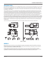
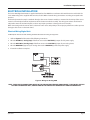
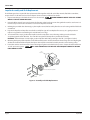
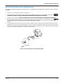
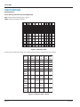
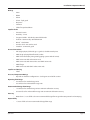
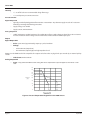
Series 4000
Flow Sensor
®
IMPORTANT:
This manual contains important information.
READ AND KEEP FOR REFERENCE.
872121-EN (April 2012)
Rev. 2
Installation & Operation Manual
Series 4000
Page ii
April 2012
Installation & Operation Manual
CONTENTS
INTRODUCTION . . . . . . . . . . . . . . . . . . . . . . . . . . . . . . . . . . . . . . . . . . . . . . . . . . . . . . . . . 5
MODELS . . . . . . . . . . . . . . . . . . . . . . . . . . . . . . . . . . . . . . . . . . . . . . . . . . . . . . . . . . . . . . 5
MECHANICAL INSTALLATION . . . . . . . . . . . . . . . . . . . . . . . . . . . . . . . . . . . . . . . . . . . . . . . . . 6
General . . . . . . . . . . . . . . . . . . . . . . . . . . . . . . . . . . . . . . . . . . . . . . . . . . . . . . . . . . . . 6
Installation for PVC Sensors. . . . . . . . . . . . . . . . . . . . . . . . . . . . . . . . . . . . . . . . . . . . . . . . 6
Installation of PVDF Sensors . . . . . . . . . . . . . . . . . . . . . . . . . . . . . . . . . . . . . . . . . . . . . . . 6
ELECTRICAL INSTALLATION . . . . . . . . . . . . . . . . . . . . . . . . . . . . . . . . . . . . . . . . . . . . . . . . . . 7
Electrical Wiring-Digital Unit . . . . . . . . . . . . . . . . . . . . . . . . . . . . . . . . . . . . . . . . . . . . . . . 7
Impeller Assembly and Shaft Replacement. . . . . . . . . . . . . . . . . . . . . . . . . . . . . . . . . . . . . . 8
Detecting Coil and Electronic Assembly Replacement. . . . . . . . . . . . . . . . . . . . . . . . . . . . . . . 9
REPLACEMENT PART NUMBERS . . . . . . . . . . . . . . . . . . . . . . . . . . . . . . . . . . . . . . . . . . . . . . 10
CALIBRATION . . . . . . . . . . . . . . . . . . . . . . . . . . . . . . . . . . . . . . . . . . . . . . . . . . . . . . . . . . 12
CALIBRATION TABLE-DIGITAL OUTPUT . . . . . . . . . . . . . . . . . . . . . . . . . . . . . . . . . . . . . . . . . . 13
SPECIFICATIONS . . . . . . . . . . . . . . . . . . . . . . . . . . . . . . . . . . . . . . . . . . . . . . . . . . . . . . . . 14
TROUBLESHOOTING. . . . . . . . . . . . . . . . . . . . . . . . . . . . . . . . . . . . . . . . . . . . . . . . . . . . . . 17
General . . . . . . . . . . . . . . . . . . . . . . . . . . . . . . . . . . . . . . . . . . . . . . . . . . . . . . . . . . . 17
TROUBLESHOOTING THE SENSOR . . . . . . . . . . . . . . . . . . . . . . . . . . . . . . . . . . . . . . . . . . . . . 17
Digital Circuit. . . . . . . . . . . . . . . . . . . . . . . . . . . . . . . . . . . . . . . . . . . . . . . . . . . . . . . . 17
Analog Circuit . . . . . . . . . . . . . . . . . . . . . . . . . . . . . . . . . . . . . . . . . . . . . . . . . . . . . . . 18
April 2012
Page iii
Series 4000
Page iv
April 2012
Installation & Operation Manual
INTRODUCTION
Data Industrial® nonmagnetic flow sensors by Badger Meter provide an accurate measurement of liquid flow. The Series 4000
flow sensor covers applications for ½" to 1" pipe sizes and a wide range of pressure/temperature specifications. When used
in conjunction with Badger Meter Series 1500, Series 2000, and Series 300 electronics, the measurement may be displayed or
transmitted as a rate or total.
The Series 4000 sensors consist of a molded housing, rotating impeller, and externally mounted electronics housing using
a proprietary, nonmagnetic sensing technology. The closed six-bladed impeller design provides higher and more constant
torque than four-bladed designs, and is less prone to fouling by water borne debris. The shape of the impeller and the
absence of magnetic drag provides improved operation and repeatability even at low flow rates. The housing design allows
the impeller, bearings, shaft, or o-rings to be cleaned or replaced without removing the sensor from the piping system.
Two signal output options are available. One option is a five volt DC square wave frequency proportional to flow rate. Power
for the circuit is provided by a Badger Meter flow monitor or other external source via a three-wire shielded cable. An internal
preamplifier allows the signal to travel 2,000 feet without amplification, 20 feet of three conductor cable is provided with this
option. The second output option is a 4-20mA current analog signal. Power is provided by the two wire loop so the distance
from the receiver is a function of power supply voltage and wire resistance. A 30 inch connector cable is provided with the
analog version.
Sensors of similar type are interchangeable, so there is no need for recalibration after servicing or replacement.
Figure 1: Models
MODELS
Badger Meter provides several basic sensor configurations using the same impeller element. This allows for a wide range
of applications and pipe sizes. Standard configurations use the materials listed above for wetted parts in the housing and
closure. Consult factory for availability of other materials.
All Series 4000 sensor electrical components are self-contained. They may be replaced in the field without requiring
recalibration or breakdown of the piping system. Pressure/temperature ratings for the various models are contained in the
Specifications section of this manual. The Series 4000 flow sensor models are summarized in the tables above.
April 2012
Page 5
Series 4000
MECHANICAL INSTALLATION
General
The accuracy of flow measurement for all flow measuring devices is highly dependent on proper location of the sensor in the
piping system. Irregular flow velocity profiles caused by valves, fittings, pipe bends, etc. can lead to inaccurate overall flow
rate indications even though local velocity measurement may be accurate. A sensor locates the pipe where it can be affected
by air bubbles, floating debris, or sediment may not achieve full accuracy, and could be damaged. Badger Meter flow sensors
are designed to operate reliably under adverse conditions, but the following recommendations should be followed to ensure
maximum system accuracy:
1.
Choose a location along the pipe where 10 pipe diameters of straight pipe upstream and five pipe diameters of straight
pipe downstream of the sensor provide no flow disturbance. Pipe bends, valves, other fittings, pipe enlargements and
reductions should not be present in this length of pipe.
2.
The preferred orientation for horizontal flow is with the curved portion of the sensor housing down. Sensors installed
with the curved portion in the up position could trap air causing inaccurate flow measurement, especially at low flows.
Sensors installed with the curved portion pointing sideways may not only trap air, but increase impeller friction, which
may also affect measurements at low flow rates. Locate sensor to facilitate servicing.
3.
The preferred vertical location is with liquids flowing up. If vertical flow downward is the only option, the pipe must
be completely filled with fluid. Any circumferential orientation is correct, but the sensor should be located to facilitate
servicing. A vertical location may result in reduction of accuracy.
4.
Sensors must be mounted in such a way to provide a minimum of 3 inches (75mm) clearance in all directions around
the blue electronics assembly to prevent electro-mechanical interference. This space requirement applies to multiple
4000 sensors installed in close proximity as well as to other EMI generators such as electric motors or controls for motors,
heaters, or lighting.
Installation for PVC Sensors
Ten diameters of straight pipe upstream and five diameters downstream are supplied with the PVC sensor in the form of
attached schedule 80 plain end pipe nipples. Any compatible size and type of fitting or adapter may be connected to the
pipe nipples by thermal or solvent welding. Be sure the fittings and method you choose to install the PVC unit complies with
American Society for Testing and Materials (ASTM) standards. Proper installation has the arrow in the stainless steel cover
pointing the same direction as the flow of the fluid. Do not connect directly to reducing (or enlarging) fittings. An additional
10 diameter upstream and five diameter downstream allowance should be made if this is unavoidable.
Installation of PVDF Sensors
PVDF sensors are supplied with combination end connections. A socket sized to accept most metric sized PVDF pipe may be
used for direct thermal welding. In addition, there is an external thread compatible with George Fisher PVDF union fittings
for use with existing fittings. PVDF flow sensors may also be purchased with George Fischer unions that terminate in metric
dimension sockets, or a wide variety of threaded or flanged connections.
In PVDF sensors with the enhanced flow feature, the flow enhancement jet must be inserted before installing the sensor into
the system. With the stainless steel cover facing you, insert the jet into the left socket (upstream end) and then perform the
method chosen for installation. Proper sensor orientation is with the arrow on the stainless steel cover pointing in the same
direction as the flow of the liquid. The same ten and five diameter upstream and downstream allowance and orientation
recommendations, as described under Installation for PVC sensors above, must be followed.
Page 6
April 2012
Installation & Operation Manual
ELECTRICAL INSTALLATION
The Series 4000 digital transmitter is supplied with 20 feet of 20 AWG three conductor cable with drain wire and shield. The
Series 4000 analog unit is supplied with 30 inches of cable. Make electrical wiring connections according to accepted trade
practices.
An electrical junction box may be attached directly to the sensor electronic module, or mounted in the vicinity of the sensor.
Locate it conveniently to facilitate replacement of the electronic module assembly. The wiring connections should not be
subjected to water of conductive liquids, as these may impair operations or damage the sensor circuitry.
When connecting to the electronic device, observe the wire colors and polarity to insure proper performance and to prevent
damage to the sensor or electronic device.
Electrical Wiring-Digital Unit
4-20mA power must be off and all wiring should be done before turning on loop power.
1.
Refer to Figure 2 for illustration of the following instructions.
2.
Wire the Red Wire (+ Analog loop) of the flow sensor to the POSITIVE (+) output of a DC power supply.
3.
Wire the Black Wire (- Analog Loop) of the flow sensor to the POSITIVE (+) input of your analog device.
4.
Wire the NEGATIVE (-) input of your analog device to the NEGATIVE (-) of the DC power supply.
5.
Electrical installation complete.
(Vintage Units)
Figure 2: Wiring For Analog 4000
NOTE: THERE ARE TWO ADDITIONAL WIRES IN THE SENSOR CABLE (BROWN AND ORANGE). THESE WIRES ARE FOR
FACTORY CALIBRATION ONLY, CONNECTING TO THESE WIRES MAY DAMAGE UNIT AND VOID WARRANTY.
April 2012
Page 7
Series 4000
Impeller Assembly and Shaft Replacement
The following tools are required for the replacement of the impeller and shaft: 5/32" Allen wrench, flat blade screwdriver,
torque driver in “in-lb” with 5/32" male hex adapter. Units are factory calibrated at 12in-lbs.
1.
Depressurize the pipe on which the sensor is to be serviced.
WHILE SYSTEM IS UNDER PRESSURE.
DO NOT REMOVE SOCKET HEAD CAP SCREWS
2.
Using the Allen wrench, loosen and remove the four #10 socket head cap screws along with the stainless steel cover. It is
not necessary to remove the electronics to service the impeller and shaft.
3.
Utilizing the provided slots alternately, pry the impeller cover/shaft assembly from the sensor housing with the flat blade
screwdriver.
4.
Inspect the impeller and impeller cover/shaft assembly for signs of wear. Replace if necessary. It is good practice to
replace o-rings before reassembling. Use no lubricants on o-rings.
5.
To reassemble the sensor, position the impeller into the cavity of the sensor housing, making sure the six blades
are pointing into the flow direction. The unit will not operate if the impeller is positioned incorrectly.
EXAMPLE: If flow direction is to the right, position impeller with blades pointing to the left. (See Figure 3 below.)
6.
Orienting the keyway of the impeller cover/shaft assembly to the small slot between the two large slots and aligning the
shaft to the shaft hold of the impeller, hand press the impeller cover/shaft assembly into the sensor housing cavity.
7.
Fasten the stainless steel cover to the sensor housing using the #10 socket head cap screws. Torque the #10 hardware to
12 in-lb. pressurize system.
ALL FOUR SCREWS MUST BE IN PLACE AND TORQUED CORRECTLY BEFORE
PRESSURING SYSTEM!
Flow
Direction
PVC VERSION
IMPELLER
IMPELLER COVER/SHAFT ASSEMBLY
STAINLESS STEEL
COVER
#10 HARDWARE
Figure 3: Assembly and Shaft Replacement
Page 8
April 2012
Installation & Operation Manual
Detecting Coil and Electronic Assembly Replacement
A #1 Phillips screwdriver is required for servicing electronics. It is not necessary to depressurize or drain the system to service the
electronics.
1.
Disconnect sensor wiring from display or transmitter.
2.
Using a Phillips screwdriver, loosen and remove the two #4 Phillips head screws and accompanying hardware.
LETTING ELECTRONIC ASSEMBLY DROP FROM SENSOR COULD DAMAGE DETECTING COIL.
3.
Unplug coil from electronics NOTE: ON ANALOG UNITS THE COIL IS PERMANENTLY ATTACHED TO ELECTRONICS.
4.
Plug coil to replacement electronics and reattach the electronics to the sensor with the two #4 Phillips screws.
BE SURE WIRES FROM COIL ARE TUCKED IN BEFORE TIGHTENING SCREWS. (See next page for replacement part
numbers).
5.
To replace detecting coil, first remove the electronic assembly per Step 1. Unplug coil from electronics. Remove the two
#6 Phillips head screws, the coil retaining plate and secure to sensor housing with the #6 hardware. Plug replacement coil
to electronic assembly and fasten the electronics to the sensor with the hardware (see the next page for replacement part
numbers.) The coil wire orientation is not critical to the operation.
COIL
IMPELLER BODY
COIL RETAINING PLATE
#6 HARDWARE
ELECTRONIC ASSEMBLY
#4 HARDWARE
Figure 4: Coil and Electronic Assembly Replacement
April 2012
Page 9
Series 4000
REPLACEMENT PART NUMBERS
Impeller
08010
Coil Kit (for digital output unit only)
(1) coil
(1) retaining plate
(2) #6 screws
711333
O-Ring Kit
PVDF units only for use with Unions
O-Ring Kit, EPDM O-Rings, 1/2" for 20 mm Union
4003OKE
O-Ring Kit, EPDM O-Rings, 3/4" for 25 mm Union
4013OKE
O-Ring Kit, EPDM O-Rings, 1" for 32 mm Union
4023OKE
O-Ring Kit, Viton O-Rings, 1/2" for 20 mm Union
4003OKV
O-Ring Kit, Viton O-Rings, 3/4" for 25 mm Union
4013OKV
O-Ring Kit, Viton O-Rings, 1" for 32 mm Union
4023OKV
Union Kit 1/2" (20mm) PVDF
(2) PVDF Union Ends, 20 mm
(2) PVDF Union Nuts, 20 mm
(2) Viton O-Rings
711380
Union Kit 3/4" (25mm) PVDF
(2) PVDF Union Ends, 25 mm
(2) PVDF Union Nuts, 25 mm
(2) Viton O-Rings
711381
Union Kit 1" (32mm) PVDF
(2) PVDF Union Ends, 32 mm
(2) PVDF Union Nuts, 32 mm
(2) Viton O-Rings
711382
Page 10
April 2012
Installation & Operation Manual
Example: 400P 2RK
COVER MATERIAL
PVC
2RK
PVDF
3RK
COVER O-RING
Viton®
EPDM
Kalrez ®
Food Grade Silicon
Neoprene®
Chemraz ®
Teflon® Encapsulated Viton®
Teflon Encapsulated Silicon
Buna N
Aflas ®
Kalrez Cover/TFE Encapsulated Viton
SHAFT
Zirconia Ceramic
Hastalloy ® C
Tungsten Carbide
Titanium
Monel®
316 Stainless Steel
Tantalum
Sapphire
IMPELLER
Tefzel®
BEARING
UHMWPE
Tefzel®
Teflon
-
0
0
2
2
0
1
2
3
4
5
6
7
8
9
A
0
1
2
3
5
6
7
9
2
1
2
3
Figure 5: Series 4000 Impeller Repair Kit
Example: 4000EK
ELECTRONICS
Pulse output
Pulse output with EFI foil shield
CE Pulse output
4-20mA analog output
4-20mA analog output with foil shield
CE 4-20mA analog output
-
10
00
01
05
10
11
15
Figure 6: Series 4000 Electronics Repair Kit Matrix
April 2012
Page 11
Series 4000
CALIBRATION
If you are replacing an existing Series 4000 sensor and have already calibrated your flow monitor, no calibration changes are
necessary. For installation of a new flow monitor, please refer to the calibration instructions in the flow monitor manual.
The Series 4000 flow sensor, like all impeller or turbine flow meters, operates by converting kinetic energy (in the flow stream)
into rotation (of an impeller). Indeed, almost all flow sensors work on the principle of converting flow energy to output
signals. The only arguable exceptions are ultrasonic and electromagnetic sensors. The interaction of the flow stream and
the impeller depend, to a currently unquantified extent, on fluid properties (density, viscosity, and pressure), and on physical
properties of the impeller. The Badger Meter impeller design features the following:
1.
A low mass polar moment of inertia
2.
No magnetic drag
3.
Very low eddy current drag
4.
Low bearing friction
The impeller housing forms the periphery of a rotating fluid stream, the only source of drag tending to retard the impeller.
The efficiency of this design is the key to the repeatability of sensor output at very low flow rates, and is the reason that the
pressure drop across the installed sensor is so low.
The Series 4000 flow sensors have been calibrated on the Badger Meter flow bench, shown schematically on TD4000CAL. The
calibrating fluid is untreated tap water, at ambient temperature, and at various pressures.
All calibration tests are based on average flow rate and average frequency measured during the delivery of 200 pounds
of water over the time period required to deliver that weight of water at a given flow rate. Our flow bench and calibration
practice conform to ASME/ANSI MFC-9M-1988, measurement of liquid flow in closed conduits by weighing method.
Sensors are calibrated based on the average flow rate. Flow velocity in feet per second is calculated there from based on the
theoretical pipe diameters. Data accuracy, as noted on TD4000CAL, is estimated to be the following for each individual test of
sensor/flow rate combination:
+/-0.15 percent on average flow rate (q)
+/-0.10 percent on average frequency (f )
Tests on at least 12 points across the rated flow range of the specific sensor, including at least one slightly above maximum
rated flow, and at least one slightly below minimum, were performed on at least six different samples of each of the basic
design.
Output data points (72 minimum) for each basic model were analyzed using standard regression techniques, to find the best
linear least squares fit describing flow rate (q) as a function of frequency (f ) in the form:
q=kf+b(EQ1)
The values of k and b are developed to produce the minimum summed squared differences between the actual flow rate at
an observed frequency and the flow rate predicted by EQ1 at that observed frequency. The results of this analysis indicate
that the calibration constants given below are accurate within +/- 1 percent of full scale given the following constraints:
1.
Constant pressure
2.
Constant temperature
3.
Water as the fluid medium
This 1 percent covers the effects of non linearity in the flow rate/frequency relationship and dimensional variations from
sensor to sensor.
Testing to date indicates that over a relatively broad range of operating pressure and temperature, factory calibration should
be adequate to yield results accurate within +/-1 percent of full scale in fluids not markedly different in density and viscosity
from water. Repeatability with most compatible fluids at constant pressure and temperature should be within 0.7 percent or
less, although the actual readings may be significantly in error if the viscosity and density of the sensed fluid depart drastically
from water.
PVC sensor calibration is based on flow through standard schedule 80 PVC pipe. The effects on calibration of joining the
standard schedule 80 pipe terminations in a system of other than PVC schedule 80 have not been investigated. We caution
you to anticipate some deviation in calibration. This effect can be minimized if an additional 10 to 20 diameter lengths of
Page 12
April 2012
Installation & Operation Manual
PVC schedule 80 pipe of the appropriated diameter is installed upstream of the sensor, and a similar 5 to 10 diameter lengths
downstream.
PVDF sensor calibration is based on flow through industry standard PVDF pipe. Similar action should be taken if the PVDF
sensor is used in a system based on other piping technologies.
CALIBRATION TABLE-DIGITAL OUTPUT
The following table provides calibration and operational data for the various models of the Badger Series 4000 sensor. The
data is organized as follows:
Column 1:
Model number, to which the data listed in the particular column pertains
Column 2:
Housing material
Column 3:
Nominal pipe size
Column 4:
Pipe O.D., per applicable standards
Column 5:
Pipe I.D., per applicable standards
Column 6:
Slope of the regression line used in calibration (K)
Column 7:
Intercept of the regression line (Offset)
Column 8:
Minimum recommended flow rate (GPM)
Column 9:
Maximum recommended flow rate (GPM)
Column 10:
Pulse rate at minimum flow (Hz)
Column 11:
Pulse rate at maximum flow (Hz)
The calibration constants in columns 6 and 7 relate frequency (Hz) to flow rate (GPM) in the equations:
FREQ=
GPM
K -Offset
GPM = K (FREQ + Offset)
April 2012
Page 13
Series 4000
SPECIFICATIONS
Wetted Materials
Sensor Housing and Enhancing Jet (If Applicable)
PVC - Virgin polyvinyl chloride, type 1, grade 1
PVDF - Virgin polyvinylidene fluoride
Sensor
#
Mat'l
Nom.
Pipe
Pipe
OD
Pipe
ID
K
Offset
GPM
min
GPM
max
Hz
min
Hz
max
400200
PVC
1/2 #80
.0840 in
401200
PVC
3/4 #80
1.050 in
0.546
0.413
0.3496
0.75
15.00
1.46
35.97
0.824
0.5735
0.2638
1.75
35.00
2.78
402000
PVC
1 #80
60.76
1.315 in
0.957
0.6134
0.1826
2.25
45.00
3.48
410200
PVC
73.17
1/2 #80
.0840 in
0.546
0.1421
0.8474
0.18
6.00
0.48
41.37
411200
400300
400400
400500
401300
401400
401500
402300
402400
402500
410300
410400
410500
411300
411400
411500
PVC
3/4 #80
1.050 in
0.824
0.3287
0.2159
0.40
13.00
1.00
39.33
PVDF
1/2"
20mm 16.2mm 0.5987
(0.787in) (0.638in)
0.0008
1.00
20.00
1.66
33.40
PVDF
3/4"
25mm 21.2mm
(0.984in) (0.835in)
0.613
0.02664
1.75
35.00
2.82
57.06
PVDF
1"
32mm 27.2mm 0.6266
(1.260in) (1.071in)
0.0314
3.00
50.00
4.75
79.76
PVDF
1/2"
20mm 16.2mm 0.1445
(0.787in) (0.638in)
0.4841
0.25
8.00
1.24
54.87
PVDF
3/4"
25mm 21.2mm 0.3195
(0.984in) (0.835in)
0.4679
0.40
14.00
0.78
44.28
Figure 7: Calibration Table
Analog versions of the Series 4000 are precalibrated at the factory using the flow ranges below.
Sensor
#
Mat'l
Pipe
ID
4mA
Flow
20mA
Flow
400210 PVC 1/2 #80 .0840 in
0.546
0
20
401210 PVC 3/4 #80 1.050 in
0.824
0
30
402010 PVC
1.315 in
0.957
0
40
410210 PVC 1/2 #80 .0840 in
0.546
0
8
411210 PVC 3/4 #80 1.050 in
0.824
400310
400410
400510
401310
401410
401510
402310
402410
402510
410310
410410
410510
411310
411410
411510
PVDF
PVDF
PVDF
PVDF
PVDF
Nom.
Pipe
1 #80
1/2"
3/4"
1"
1/2"
3/4"
Pipe
OD
0
12
20mm 16.2mm
(0.787in) (0.638in)
0
20
25mm 21.2mm
(0.984in) (0.835in)
0
30
32mm 27.2mm
(1.260in) (1.071in)
0
40
20mm 16.2mm
(0.787in) (0.638in)
0
8
25mm 21.2mm
(0.984in) (0.835in)
0
12
Figure 8: Calibration Table - Analog
Page 14
April 2012
Installation & Operation Manual
O-Rings
•
Viton®
•
EPDM
•
Kalrez®
•
Silicon - food grade
•
Neoprene®
•
Chemraz®
•
Teflon® Encapsulated Viton
Impeller Shafts
•
Zirconia Ceramic
•
Hastelloy® - C-276
•
Tungsten Carbide - GE carboloy 883 colbalt binder
•
Titanium - titanium alloy 86Ti-6AL-6V-25A
•
Monel® - Grade K500
•
Stainless Steel - 316 stainless steel
•
Tantalum - commercial grade
Process Connections
•
PVC (virgin polyvinyl chloride, type 1, grade 1) schedule 80 tail pieces
•
PVDF (virgin polyvinylidene fluoride) sockets
•
PVDF union thread (for joining existing piping systems with GF unions)
•
PVDF union nuts with socket union ends
•
PVDF union nuts with 316 stainless steel FNPT union ends
•
PVDF flanges
•
PVDF union nuts with CPVC socket union ends
Impeller and Bearing
•
Tefzel®
Pressure, Temperature Ratings
•
Depends on hardware configurations. See diagram at end of this section.
Operating Flow Range
•
0 to 20 ft/sec for standard range units
•
0 to 10 ft/sec for enhanced flow range units
Recommended Design Flow Range
•
1 to 20 ft/sec for standard range units to maintain calibration accuracy
•
0.25 to 8 ft/sec for enhanced flow range units to maintain calibration accuracy
Accuracy
•
Better than +/- 1.0% of full scale over recommended design flow range with water @50-80 F and 20-40 psig
Repeatability
•
April 2012
+/- 0.5% of full scale over recommended design flow range
Page 15
Series 4000
Linearity
•
+/- .7% of full scale over recommended design flow range
•
+/- 1.0% frequency to current conversion
Transducer Power
Digital Output Unit
•
Typically provided by Badger Meter flow monitor or transmitter. Any alternate supply must be of a resistancelimited type meeting the following constraints:
•
Supply voltage: 9 to 20 VDC
•
Supply current: 2mA maximum
Analog Output Unit
•
10 VDC minimum to 35 VDC maximum. The combination of loop supply voltage and total loop series resistance
must insure that the device voltage remains within these limits over the 4-20mA output span.
Output
Digital Output Unit
•
Pulse: square wave (approximately) output @ 1 pulse/revolution
•
Voltage:
•
0.4 V maximum (output low)
•
45 V minimum (output high) into high impedance load
Output is 5 volt CMOS and LSTTL compatible. The output can be forced to any logic level up to 20 volts by an external pull-up
resistor.
•
Sink Current: 2mA maximum
Analog Output Unit
•
Signal: Loop powered 4-20mA current analog with offset compensation output for ripple less then 0.25% of full
scale.
400
350
300
275
250
Pressure
(psi)
200
150
100
PVC
PVDF
50
0
50
100
140
150
200
220
250
Figure 9: Pressure Temperature Diagram for Series 4000 Sensors
Page 16
April 2012
Installation & Operation Manual
TROUBLESHOOTING
General
Primary consideration for troubleshooting a Series 4000 flow sensor is to first establish that the problem lies with the sensor
and not with the electronic device connected to it. A simple way to help determine this is to substitute a known working
sensor for the suspect unit. If the electronics react in an appropriate manner, you may conclude that the problem is sensor
related. Another option would be to provide a similar, square wave pulse simulation by hooking up a frequency generator to
the interface electronics and simulating as close as possible the actual sensor signal.
If you suspect a sensor problem, there are a few mechanical considerations to be addressed:
1.
Make sure there is flow in the pipe line appropriate to the operations range (0.25-20 feet/second) of the sensor.
2.
Make sure that the wiring between the sensor and the electronics is correct. If a junction box has been added, also make
sure that all wiring connections are right.
3.
Check the impeller assembly to make sure it is not mounted in the reverse direction of flow.
4.
Make sure that the impeller can spin freely on the shaft and that no foreign matter of debris has lodged in the sensor
housing.
TROUBLESHOOTING THE SENSOR
Digital Circuit
A sensor is a powered device, required voltage between 8VDC and 20 VDC, applied between the red (+) and black (-) sensor
leads. The sensor will normally draw about 1mA for this supply. WARNING: DO NOT EXCEED 20 VDC; SENSOR DAMAGE
MAY RESULT.
1.
The white sensor wire should be disconnected. Make sure that the black, red and shield wires remain connected to the
proper terminals.
2.
Install a voltmeter, positive (+) to the white sensor wire and negative (-) to the black sensor wire. If flow exists, you
should see a square wave switching between 0.0 VDC (low) and 4.0 VDC (high). NOTE: The pulse may be too fast for the
voltmeter to recognize as a square wave, but it may appear as an unstable reading somewhere between 2.0 and 4.9 VDC.
If flow is stopped, the output will hold in either a high (4.0 VDC) state or low (0.0 VDC) state, depending on the position of
the impeller reflector or other factors. To simulate impeller rotation, simply pass a metal object (i.e. large screwdriver or
pliers) past the back of the sensor. The output signal should then switch states.
3.
If the sensor produces pulses in the above tests, reconnect the white sensor wire to the signal input terminal of the
transmitter. With the voltmeter still connected, note the actual voltage levels between the output switching (such as 0.0
VDC low or 4.0 VDC high). If reconnecting the sensor to the transmitter either stops or significantly alters the voltage
levels of the pulses, or if the transmitter does not respond to the pulses, consult the factory or your local representative.
4.
A nonworking sensor could be the result of either a sensing coil failure or a component failure in the electronic module
(blue cover). Using an ohm meter, determine the coil resistance by removing the blue electronics cover containing the
encapsulated circuitry. Unplug the coil from the electronics in the cover. Connect the probes of the ohm meter to the
wire terminals of the coil plug-in connector. The coil resistance should measure between 5 and 10 Ohms. A very low or
very high resistance reading may indicate failed coil; if this appears, replace the coil.
5.
If the coil appears to be within specification, replace the blue cover assembly from another working device. If the sensor
begins working, replace the electronic assembly.
6.
If the sensor switches states when a metal object is passed near the back of the sensor, but no pulse occurs when flow
exists, verify that the flow meets our minimum flow requirements for the sensor. Check further the condition of the
impeller and the shaft for mechanical wear or damage. If replacement is necessary, a repair kit is available containing the
appropriate components.
April 2012
Page 17
Series 4000
7.
If the sensor was working and a rebuild kit was installed due to a failure of the impeller or shaft and the sensor did not
return to working order, check to ensure that the impeller was installed in the proper direction. If the impeller was
installed backwards to the flow direction, no signal pulse will be generated even if the impeller spins freely.
8.
Should you experience any other difficulties with the sensor, please consult the factory or your local representative.
Please have a description of the problem, model, serial number, and application information available when you call.
Analog Circuit
1.
Connect power supply and ammeter in a series loop.
2.
With no flow in the pipe, check to see if the output is reading 4mA. If the output is greater or less than 4mA then the
analog electronics assembly must be recalibrated at factory.
3.
With flow in the pipe the output should be something higher than 4mA but not greater than 20mA. If you cannot get
flow through the system you can simulate flow two ways. The first way is to blow into one side of the unit to make
impeller spin and the other is to pass a metal object (nut driver, wrench, etc...) across the back of the electronics housing.
Either one of the last two methods will excite the analog output to change and read greater then 4mA.
4.
If the analog output does not change with any of the actions done in step three then the electronics assembly is
defective.
5.
If the analog changes when you pass a metal object across the rear of the electronics assembly but does not at any other
time then inspect the impeller assembly.
Page 18
April 2012
Installation & Operation Manual
(This page intentionally left blank.)
April 2012
Page 19
Please see our website at
www.badgermeter.com
for specific contacts.
www.badgermeter.com
Data Industrial® is a registered trademark of Badger Meter, Inc.
Other trademarks appearing in this document are the property of their respective entities.
Due to continuous research, product improvements and enhancements, Badger Meter reserves the right to change product or system specifications without notice,
except to the extent an outstanding contractual obligation exists. © 2012 Badger Meter, Inc. All rights reserved.
Badger Meter | PO Box 245036, Milwaukee, Wisconsin 53224-9536 | 800-876-3837 | [email protected]