1
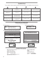
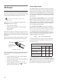
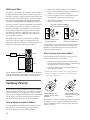
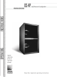
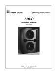
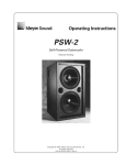
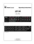
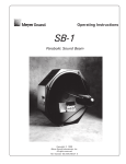
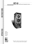
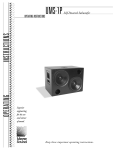
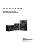
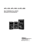
PSM-2
Operating Instructions
Patents
Pending
Self-Powered Stage Monitor
PSM-2 at 55°
PSM-2 at 35 °
The PSM-2 self-powered stage monitor contains
independent amplifier and control electronics for one
12” cone driver and one 4” diaphragm horn driver in a
compact enclosure. This integrated design eliminates
amplifier racks, improves durability and reliability,
and simplifies setup and installation.
varying speaker impedance by measuring current, in
addition to voltage, to compute the power dissipation
and voice coil temperature.
The PSM-2 can be oriented such that the planes of the
cabinet face and the horizontal surface on which the
PSM-2 is placed form a 35°, 55°, or 90° angle. Its top-tobottom profile is 20.5” at 35°, and 19.5” at 55° (1” higher
than the Meyer UM-1). The high-Q horn provides uniform
coverage in both the horizontal and vertical planes.
The PSM-2 has the following acoustical specifications:
Frequency Response
± 4 dB 50 Hz – 18 kHz
Max Peak SPL at 1 m
139 dB
Dynamic Range
> 110 dB
Coverage
–6 dB: 50° H x 50° V
–10 dB: 70° H x 70° V
The PSM-2 is phase-corrected through the crossover
and has an overall phase response of ±90° 200 Hz–16 kHz,
which yields exceptional system impulse response
and accurate reproduction of all signals.
The PSM-2 employs TruPower™ limiting (TPL), the
first limiting technique that accurately calculates the
power dissipation within the speaker. TPL accounts for
All Meyer self-powered speakers use TPL, which
• allows the speaker to produce its highest SPL
across its entire frequency range during limiting;
• eliminates long-term power compression when
the loudspeaker is operated at high levels for
extended periods;
• protects the drivers and extends the lifetime of
amplifier and driver components.
The PSM-2 uses the Intelligent AC™ power supply,
which protects the amplifier and drivers by autoselecting the voltage, minimizing inrush current, filtering
EMI, and performing surge suppression. The dualchannel amplifier (620 W/channel) is cooled by a variablespeed primary fan that runs continuously, and a
secondary fan that turns on when the PSM-2 is operated
in hot conditions or at its maximum level for an
extended period.
The PSM-2 can be equipped to operate with the Remote
Monitoring System™ (RMS) interface network and
software application. RMS displays signal and power
levels, driver and cooling fan status, limiter activity,
and amplifier temperature for all speakers in the
network on a Windows-based PC.
Symbols Used
These symbols indicate important safety or operating features in this booklet and on the chassis.
!
Dangerous voltages:
risk of electric shock
Important operating
instructions
Frame or chassis
Protective earth ground
Pour indiquer les risques
résultant de tensions
dangereuses
Pour indequer important
instructions
Masse, châssis
Terre de protection
Zu die gefahren von
gefährliche spanning zeigen
Zu wichtige betriebsanweisung und unterhaltsanweisung zeigen
Rahmen oder chassis
Die schutzerde
Para indicar azares provengo
de peligroso voltajes
Para indicar importante
funcionar y mantenimiento
instrucciones
Armadura o chassis
Tierra proteccionista
Declaration of Conformity
According to ISO/IEC Guide and EN 45014
The Manufacturer:
declares that the product:
Product Name:
PSM-2
Product Options: All
Name:
Meyer Sound Laboratories
Address: 2832 San Pablo Avenue
Berkeley, California 94702-2204, USA
conforms to the following Product Specifications:
Safety:
EMC:
EN 60065: 1994
EN 55022: 1987
IEC 801-2: 1984
IEC 801-3: 1984
IEC 801-4: 1984
-
Class A
8 kV
3 V/m
0.5 kV Signal Lines,
1.0 kV Power Lines
The product herewith complies with the requirements of the Low Voltage Directive 73/23/EEC and
the EMC Directive 89/336/EEC.
Office of Quality Manager
Berkeley, California USA
October 1, 1995
Environmental Specifications for
Meyer Sound Electronics Products
Operating temperature:
0° C to +45° C
Non-operating temp:
< –40° C or > +75° C
Humidity:
to 95% at 35°C
Operating altitude:
to 4600 m (15,000 ft)
Nonoperating altitude:
Shock:
to 6300 m (25,000 ft)
30 g 11 msec half-sine
on each of 6 sides
10 – 55 Hz (0.010 m
peak-to-peak excursion)
Vibration:
Made by Meyer Sound, Berkeley, CA, USA
U
® L
UL
LISTED
3K59 C ®
COMMERCIAL
AUDIO SYSTEM
European Office:
Meyer Sound Germany
GmbH
Carl Zeiss Strasse 13
56751 Polch, Germany
Contact Information
Meyer Sound Laboratories, Inc.
2832 San Pablo Avenue
Berkeley, California 94702
Telephone: 510 - 486 - 1166
FAX:
510 - 486 - 8356
E-mail: [email protected]
http://www.meyersound.com
2
Meyer Sound Germany
Gmbh
Carl Zeiss Strasse 13
56751 Polch, Germany
Telephone: 49.2654.9600.58
FAX:
49.2654.9600.59
Contents
Controls and Connectors ..................................
Dimensions ........................................................
AC Power ...........................................................
Audio Input ........................................................
Limiting and Protection Circuitry .....................
Example Applications ....................................... 7
Verifying Polarity ............................................... 8
Safety Summary ................................................ 9
Specifications .................................................. 10
3
3
4
5
6
Controls and Connectors
!
WARNINGS:
THIS PRODUCT MUST BE GROUNDED
This surface may reach high temperatures while in use.
To ensure proper operation, allow at least 6 inches
clearance from this surface and adequate ventilation.
To reduce the risk of electric shock do not remove cover.
No operator serviceable parts inside.
Refer servicing to qualified personnel.
To reduce the risk of fire or electric shock
do not expose this appliance to rain or moisture.
Mains circuit
breakers
-I T
IRK
UK WARNING : THIS APPARATUS MUST BE EARTHED.
NO OPERATOR SERVICEABLE PARTS INSIDE.
REFER SERVICING TO QUALIFIED PERSONNEL
PUSH
2+
10K Ω
ENTRETIEN ET REPARATIONS
INTERNES NE SONT AUTORISEES QU'AU
PERSONNEL TECHNIQUE QUALIFIÉ
-I T
RE
Input Polarity
Power LED (green/red)
ATTENTION :
S
PU H
-C
Active / Speaker Fault
Auto-Voltage Select
95-125V
208-235V
50-60Hz
50-60Hz
1400W RMS MAX 1400W RMS MAX
3+
~
Balanced
~
-C
1
ESD
220K Ω
Case
Signal input and
loop connectors
2
3
1
1
3
es
ity
ct
Network
A
R
iv
et
e
ic
k
in
W
rv
Se
Remote
Monitoring
-C
System
ATTENTION : ENTRETIEN ET
INTERNES NE SONT AUTORIU
S
PU H
RE
Remote Monitoring
System panel
(if RMS is installed)
Loop
ACHTUNG : GEHÄUSE NICHT
UND REPARATUR NUR DURCH
IRK
2
Earth / Chassis
Input
ATENCIÓN : ACCESO INTER
AUTORIZADO A PERSONAL TÉ
S
PU H
RE
Input polarity switch
This surface may reach high t
To ensure proper operation, allow
clearance from this surface and ad
To reduce the risk of electric shoc
No operator serviceable parts insi
Refer servicing to qualified person
To reduce the risk of fire or electr
do not expose this appliance to ra
ACHTUNG : GEHÄUSE NICHT ÖFFNEN WARTUNG
UND REPARATUR NUR DURCH ELEKTROFACHKRÄFTE
IRK
HI Limit
LO Limit
!
WARNINGS:
THIS PRODUCT M
-I T
RE
-C
High Limit (red)
Low Limit (red)
Tie-wrap anchor
ATENCIÓN : ACCESO INTERNO SOLO
AUTORIZADO A PERSONAL TÉCNICO CALIFICADO
S
PU H
Meyer Sound, Berkeley, CA. USA
PERSONNEL TECHNIQUE QUA
-I T
PSM-2
Mains AC inlet
IRK
UK WARNING : THIS APPAR
NO OPERATOR SERVICEABLE PA
REFER SERVICING TO QUALIFIED
PUSH
Auto-Voltage Select
5
10A RMS
1
20A Peak
2
88-127V
5
50-60Hz
700W RMS MAX 7
~
2
3
1
1
3
et
ic
es
k
A
R
rv
in
W
Se
Input
~
~
2
e
Rear User Panel shown with the optional
Remote Monitoring System (RMS) panel
Operational voltage
Turn on 80V
Tur
Tur
Turn on 160V
ct
iv
ity
Network
Loop
Remote
Monitor
System
Meyer Sound, Be
European User Panel with
IEC 309 connector
Dimensions
All units in inches
Front
Side
Top
6.2
12.1
35°
55°
18.0
18.0
12.1
24.0
24.0
14.7
Grill shown here
is 1.5" thick
3
Power Requirements
AC Power
The AC voltage operating ranges for the PSM-2 are
85–134 V and 165–264 V, at 50 or 60 Hz. The PSM-2
performs surge suppression for high voltage transients
and can safely withstand voltages up to 275 VAC.
Continuous voltages above 275 VAC may
damage the unit!
When an AC source is applied to the PSM-2, the
Intelligent AC power supply
•
auto-selects the voltage;
•
performs surge suppression and minimizes
inrush current;
•
filters EMI.
After three seconds, the main power supply is slowly
ramped on. The PSM-2 uses a NEMA L6-20P or IEC 309
male power inlet and satisfies UL, CSA, and EC safety
standards.
Use the following AC cable wiring diagram to create
international or special-purpose power connectors:
brown = hot
blue =
neutral
yellow/green =
earth ground
(chassis)
AC cable color code
If the colors referred to in the diagram don't correspond
to the terminals in your plug, use the following
guidelines:
• Connect the blue wire to the terminal marked
with an N or colored black.
• Connect the brown wire to the terminal marked
with an L or colored red.
• Connect the green and yellow wire to the
terminal marked with an E (or ) or colored
green (or green and yellow).
4
The PSM-2 presents a dynamic load to the AC mains
which causes the amount of current to fluctuate between
quiet and loud operating levels. Since different types
of cables and circuit breakers heat up at varying rates,
it is essential to understand the types of current ratings
and how they correspond to circuit breaker and cable
specifications.
The maximum continuous RMS current is the maximum
RMS current in a period of at least 10 seconds. It is
used to calculate the temperature increase in cables,
which is used to select cables that conform to electrical
code standards. It is also used to select the rating for
slow-reacting thermal breakers.
The maximum burst RMS current is the maximum
RMS current in a period of approximately 1 second. It
is used to select the rating for most magnetic breakers.
The maximum peak current during burst is used to
select the rating for fast-reacting magnetic breakers
and to calculate the peak voltage drop in long AC
cables according to the formula
Vpkdrop = Ipk x Total Cable Resistance
Use the table below as a guide to select cables and
circuit breakers with appropriate ratings for your
operating voltage.
PSM-2 Current Ratings
Max. Continuous RMS
115 V
230 V
100 V
8 ARMS
4 ARMS 10 ARMS
Max. Burst RMS
15 ARMS 8 ARMS 18 ARMS
Max. Peak During Burst
22 APEAK 11 APEAK 25 APEAK
The minimum electrical service amperage required by a
system of PSM-2s is the sum of the maximum continuous
RMS current for each speaker. We recommend allowing
an additional 30% above the minimum amperage to
prevent peak voltage drops at the service entry.
Safety Issues
Audio Input
Pay close attention to these important electrical and
safety issues.
The PSM-2 presents a 10 kΩ input impedance to a threepin XLR connector wired with the following convention:
Use a power cord adapter to drive the PSM-2
from a standard 3-prong outlet (NEMA 5-15R;
125 V max).
earth
ground
chassis
ground
The PSM-2 requires a grounded outlet. Always
use a grounding adapter when connecting to
ungrounded outlets.
Pin 1 —
220 kΩ to chassis and earth ground (ESD clamped)
Pin 2 —
Signal
Pin 3 —
Signal
Case —
Earth (AC) ground and chassis
Differential Inputs
Pins 2 and 3 carry the input as a differential signal;
their polarity can be reversed with the input polarity
switch on the user panel. If the switch is in the up
position, pin 2 is hot relative to pin 3, resulting in a
positive pressure wave when a positive signal is applied
to pin 2. Use standard audio cables with XLR connectors
for balanced signal sources.
Shorting an input connector pin to the case can
form a ground loop and cause hum.
Do not use a ground-lifting adapter or cut the
AC cable ground pin.
Keep all liquids away from the PSM-2 to avoid hazards
from electrical shock.
Do not operate the unit if the power cables are frayed
or broken; replace worn or damaged cables immediately.
Tie-wrap anchors on the amplifier chassis provide
strain relief for the power and signal cables. Insert the
plastic tie-wraps through the anchors and wrap them
around the cables.
The PSM-2 should not be installed outdoors without
weather protection. The cabinet, exposed electronic
circuitry, and drivers can all receive weather protection
treatment that allows the unit to be used safely in wet
conditions. Contact Meyer Sound for information
about weather-protected units.
A single source can drive multiple PSM-2s with a
paralleled input loop, creating an unbuffered hardwired loop connection. Make certain that the source
equipment can drive the total load impedance presented
by the paralleled input circuit. For example, since the
input impedance of a single PSM-2 is 10 kΩ, cascading
20 PSM-2s produces a balanced input impedance of
500 Ω. If a 150 Ω source is used, the 500 Ω load results
in a 2.28 dB loss.
Troubleshooting
If the Active lamp does not light after connection to an
AC source for three seconds, the problem is probably in
the power supply. In the unlikely case that the circuit
breakers trip (the white center buttons pop out), the
amplifier or power supply may be malfunctioning.
Do not reset the breakers! Contact Meyer Sound for repair
information.
If abnormal noise (hum, hiss, popping) is produced
from the loudspeaker, disconnect the audio source
from the speaker. If the noise stops, then the problem
is not within the loudspeaker; check your audio and
AC power sources.
If problems persist, contact Meyer Sound. If repairs are
necessary, the PSM-2’s modular components are easy
to remove and ship.
5
Limiting and Protection
Circuitry
TruPower Limiting System
Conventional limiters assume that the resistance of a
speaker remains constant and set the limiting threshold
by measuring voltage only. This method is inaccurate
because the speaker’s resistance changes in response
to the frequency content of the source material and
thermal variations in the speaker’s voice coil and magnet.
Conventional limiters begin limiting prematurely,
which under-utilizes system headroom and deprives
the speaker of its full dynamic range.
The TruPower limiting (TPL) system accounts for
varying speaker impedance by measuring current, in
addition to voltage, to compute the power dissipation
and voice coil temperature. TPL allows the speaker to
deliver its highest SPL across its entire frequency
range during limiting, eliminates long-term power
compression, protects the drivers, and extends the
lifetime of all components.
Hi Limit and Lo Limit LEDs on the user panel indicate
TPL activity for the high and low frequency drivers,
respectively. The limiters for each driver function
independently and do not affect the signal when the
LEDs are inactive. Limiting begins when the driver
temperature exceeds the maximum safe level and ceases
when the temperature returns to normal.
The PSM-2 performs within its acoustical specifications
and operates at a normal temperature if the TPL LEDs
are on for no longer than two seconds, and off for at least
one second. If the LEDs remain on for longer than
three seconds, the PSM-2 is hard limiting with these
negative consequences:
• Increasing the input level will not increase the
volume.
• The system distorts due to clipping and nonlinear
driver operation.
• Unequal limiting between the low and high
frequency drivers alters the frequency response.
• Driver and amplifier components are subjected
to maximum heat, which shortens their life span.
NOTE: Although the TPL limiters exhibit smooth sonic
characteristics, we do not recommend using them for
intentional compression effects. Use an outboard
compressor/limiter to compress a mixed signal.
6
Troubleshooting with TPL
The TPL LED can indicate serious driver problems, if
interpreted correctly. If one PSM-2 in a system exhibits
substantially more TPL activity than others receiving the
same audio signal, then the driver associated with
the excessively active LED may have a short circuit. This
is a potentially dangerous condition for the electronics;
shut the PSM-2 down immediately.
The TPL circuit does not activate if there is no power
dissipation in the driver, regardless of the input signal
level. Therefore, if all PSM-2s in a system receiving the
same audio signal exhibit TPL activity except one,
then that unit may have an open voice coil; disconnect
it and contact Meyer Sound for repair information.
Fans and Cooling System
The PSM-2 uses a forced-air cooling system with two
fans to prevent the amplifiers from overheating. A
variable-speed primary fan runs continuously with an
inaudible operating noise of 22 dBA at 1 m at its slowest
speed. The speed of the primary fan begins increasing
when the temperature of the heatsinks reaches 42°C.
The fan reaches full speed at 62°C and is barely audible
near the cabinet, even without an audio signal.
In the unusual event that the temperature reaches
74°C, the secondary fan turns on and is clearly audible.
The secondary fan turns on in response to
• primary fan failure (check its status immediately);
• high source levels for a prolonged period in hot
temperatures or direct sunlight;
• driver failure.
The secondary fan turns off when the temperature
decreases to 68°C.
In the highly unlikely event that the secondary fan
does not keep the temperature below 85°C, the PSM-2
automatically shuts down until AC power is removed
and reapplied. If the PSM-2 shuts down again after
cooling and reapplying AC power, contact Meyer
Sound for repair information.
The fans draw air in through ducts on the front of the
cabinet, over the heatsinks, and out the rear of the
cabinet. Since dust does not accumulate in the amplifier
circuitry, its life span is increased significantly. Make
sure that the air ducts are clear and that there is at
least 6” clearance for exhaust behind the cabinet.
PSM-2 at 35 °
With the PSM-2 at 35°, a 5’10” person is within the
coverage area when standing at distances up to about
6 ft from the monitor. The diagram below shows a
grey figure at 8 ft, outside the coverage area.
At 35°, the horn is above the 12” cone driver and the
top-to-bottom profile is 20.5”.
cooling
fans
50°
air
power
supply
heatsinks
5'10"
air
35°
A foam insert filter, in combination with the entire
front grill surface, acts as an air filter for the cooling
system. Despite the filtering, extensive use or a dusty
operating environment can allow dust to accumulate
along the path of the airflow, preventing normal cooling.
We recommend periodically removing the grill, filter,
and amplifier module and using compressed air to
clear dust from the grill, filter, fans, and heatsinks.
Example Applications
20.5"
1'
4'
8'
PSM-2 at 55 °
With the PSM-2 at 55°, a 5’10” person is within the
coverage area when standing at distances from 2 to 20 ft
from the monitor. The diagram below shows a grey
figure at 1 ft, outside the coverage area.
At 55°, the horn is to the left of the 12” driver and the
top-to-bottom profile is 19.5”.
NOTE: Orientations refer to the angle formed by the
planes of the cabinet face and the horizontal surface on
which the PSM-2 is placed; see the diagrams (right).
The PSM-2 is most often used as a stage monitor at a
35° or 55° angle. The choice of orientation depends on
the musician’s height and distance from the monitor.
In general, orient the PSM-2 at
• 35° to stand within 2 ft of the monitor;
• 55° to stand further than 6 ft from the monitor.
50°
5'10"
55°
19.5"
1'
4'
20'
The PSM-2 can be used effectively with a Meyer selfpowered subwoofer with, or without, a crossover. The
third example discusses an application without a
crossover. The Meyer LD-1A Line Driver assists using
the PSM-2 as a mid-hi speaker with a sub by providing
a crossover, mid-hi and sub level controls, and EQ
functions. Contact Meyer Sound for information about
the LD-1A.
At any orientation, the PSM-2’s coverage area is:
–6 dB points:
50° H x 50° V
–10 dB points:
70° H x 70° V
7
PSM-2 and PSW-2
The PSM-2 can be used with the Meyer PSW-2, PSW-4,
or 650-P self-powered subwoofers. However, due to the
overlap of frequency response between the PSM-2 and
the subwoofer, the system frequency response exhibits a
rise in the range 50–120 Hz. The rise can be eliminated
by the Meyer CP-10 Parametric Equalizer, if desired.
In a close-proximity coplanar orientation, set the PSM-2
and a Meyer self-powered subwoofer to the same
polarity. Although it is preferable to use the PSM-2
with a self-powered sub, the Meyer 650-R2, USW-1,
and MSW-2 externally amplified subwoofers can
also be used if the sub’s amplifier and the PSM-2 are
set to opposite polarities.
Although the 90° angle is often used for the PSM-2
with a sub, the best angle to use depends on the
musician’s height and distance from the monitor and
whether the musician is standing or seated.
CP-10 EQ
(1 Channel)
input
PSM-2
loop
1. Position two PSM-2s adjacent to each other.
2. Place a measurement microphone 6 feet from the
monitors on the axis between them.
3. Connect a signal source to one PSM-2 and note
the frequency response and overall level.
4. Apply the same signal to the second PSM-2 with
the first still connected.
Top view of adjacent PSM-2s
with measurement microphone
Correct polarity causes
acoustic addition
Opposite polarity causes
acoustic cancellation
The polarity is correct if the frequency response remains
constant with a significant increase in amplitude.
Broadband cancellation (decreased overall level)
indicates polarity reversal.
Driver Polarity in the Same PSM-2
Use the following test procedure to verify polarity
between drivers in the same PSM-2:
PSW-2
Set the PSM-2 and PSW-2 to the same polarity. All Meyer
self-powered speakers have a loop connection on the user
panel that can send the input signal to another speaker.
1. Place a monitoring microphone 3 feet from the
front of the monitor at the midway point between
the high and low frequency drivers.
2. Connect a signal source to the PSM-2 and note
the frequency response.
NOTE: Since polarity reversal causes excessive driver
excursion at high source levels, use moderate levels
when conducting this test.
Verifying Polarity
Incorrect driver polarity impairs system performance
and may damage the drivers. Every PSM-2 is shipped
with the drivers in correct alignment. However, if the
driver or circuit wiring has been removed or disassembled
for any reason, check the polarity between adjacent
monitors and between drivers in the same monitor.
Polarity Between Adjacent PSM-2s
It is essential that two PSM-2s used together have the
same polarity. Use the following test procedure to
verify the polarity between adjacent PSM-2s:
8
Drivers with correct
polarity cause acoustic
addition
Drivers with reverse
polarity cause acoustic
cancellation
The polarity is correct if the frequency response is smooth
through the crossover region (±4 dB 600 Hz–1 kHz).
Severe cancellation in the crossover region indicates
polarity reversal.
Safety Summary
English
• To reduce the risk of electric shock, disconnect the
loudspeaker from the AC mains before installing audio
cable. Reconnect the power cord only after making all
signal connections.
• Connect the loudspeaker to a two-pole, three wire
grounding mains receptacle. The receptacle must be
connected to a fuse or circuit breaker. Connection to any
other type of receptacle poses a shock hazard and may
violate local electrical codes.
• Do not install the loudspeaker in wet or humid locations
without using weather protection equipment from
Meyer Sound.
• Do not allow water or any foreign object to get inside the
loudspeaker. Do not put objects containing liquid on, or
near, the unit.
• To reduce the risk of overheating the loudspeaker, avoid
exposing it to direct sunlight. Do not install the unit near
heat emitting appliances, such as a room heater or stove.
• This loudspeaker contains potentially hazardous
voltages. Do not attempt to disassemble the unit. The
unit contains no user serviceable parts. Repairs should
be performed only by factory trained service personnel.
Deutsch
• Um die Gefahr eines elektrischen Schlages auf ein
Minimum zu reduzieren, den Lautsprecher vom
Stromnetz trennen, bevor ggf. ein AudioSchnittstellensignalkabel angeschlossen wird. Das
Netzkabel erst nach Herstellung aller
Signalverbindungen wieder einstecken.
• Der Lautsprecher an eine geerdete zweipolige
Dreiphasen-Netzsteckdose anschließen. Die Steckdose
muß mit einem geeigneten Abzweigschutz (Sicherung
oder Leistungsschalter) verbunden sein. Der Anschluß
der unterbrechungsfreien Stromversorgung an einen
anderen Steckdosentyp kann zu Stromschlägen führen
und gegen die örtlichen Vorschriften verstoßen.
• Der Lautsprecher nicht an einem Ort aufstellen, an dem
sie mit Wasser oder übermäßig hoher Luftfeuchtigkeit in
Berührung kommen könnte.
• Darauf achten, daß weder Wasser noch Fremdkörper in
das Innere den Lautsprecher eindringen. Keine Objekte,
die Flüssigkeit enthalten, auf oder neben die
unterbrechungsfreie Stromversorgung stellen.
• Um ein Überhitzen dem Lautsprecher zu verhindern,
das Gerät vor direkter Sonneneinstrahlung fernhalten
und nicht in der Nähe von wärmeabstrahlenden
Haushaltsgeräten (z.B. Heizgerät oder Herd) aufstellen.
• Im Inneren diesem Lautsprecher herrschen potentiell
gefährliche Spannungen. Nicht versuchen, das Gerät zu
öffnen. Es enthält keine vom Benutzer reparierbaren
Teile. Reparaturen dürfen nur von ausgebildetem
Kundenienstpersonal durchgeführt werden.
!
Français
• Pour réduire le risque d’électrocution, débranchez la
prise principale de l’haut-parleur, avant d’installer le
câble d’interface allant à l’audio. Ne rebranchez le bloc
d’alimentation qu’après avoir effectué toutes les
connections.
• Branchez l’haut-parleur dans une prise de courant à 3
dérivations (deux pôles et la terre). Cette prise doit être
munie d’une protection adéquate (fusible ou coupecircuit). Le branchement dans tout autre genre de prise
pourrait entraîner un risque d’électrocution et peut
constituer une infraction à la réglementation locale
concernant les installations électriques.
• Ne pas installer l’haut-parleur dans un endroit où il y a
de l’eau ou une humidité excessive.
• Ne pas laisser de l’eau ou tout objet pénétrer dans l’hautparleur. Ne pas placer de r´cipients contenant un liquide
sur cet appareil, ni à proximité de celui-ci.
• Pour éviter une surchauffe de l’haut-parleur, conservezla à l’abri du soleil. Ne pas installer à proximité
d’appareils dégageant de la chaleur tels que radiateurs
ou appareils de chauffage.
• Ce haut-parleur contient des circuits haute tension
présentant un danger. Ne jamais essayer de le démonter.
Il n’y a aucun composant qui puisse être réparé par
l’utilisateur. Toutes les réparations doivent être
effectuées par du personnel qualifié et agréé par le
constructeur.
Español
• Para reducir el riesgo de descarga eléctrica, desconecte
de la red el altoparlante antes de instalar el cable de
señalización de interfaz de la segnale. Vuelva a conectar
el conductor flexible de alimentación solamente una vez
efectuadas todas las interconexiones de señalizatción.
• Conecte el altoparlante a un tomacorriente bipolar y
trifilar con neutro de puesta a tierra. El tomacorriente
debe estar conectado a la protección de derivación
apropiada (ya sea un fusible o un disyuntor). La
conexión a cualquier otro tipo de tomacorriente puede
constituir peligro de descarga eléctrica y violar los
códigos eléctricos locales.
• No instale el altoparlante en lugares donde haya agua o
humedad excesiva.
• No deje que en el altoparlante entre agua ni ningún
objeto extraño. No ponga objetos con líquidos encima de
la unidad ni cerca de ella.
• Para reducir el riesgo de sobrecalentamiento, no
exponga la unidad a los rayos directos del sol ni la
instale cerca de artefactos que emiten calor, como estufas
o cocinas.
• Este altoparlante contiene niveles de voltaje peligrosos
en potencia. No intente desarmar la unidad, pues no
contiene piezas que puedan ser repardas por el usuario.
Las reparaciones deben efectuarse únicamente por parte
del personal de mantenimiento capacitado en la fábrica.
9
Specifications
Acoustical
± 4 dB 50 Hz – 18 kHz
± 90° 200 Hz – 16 kHz
139 dB peak at 1 m
> 110 dB
–6 dB: 50° H x 50° V; –10 dB: 70° H x 70° V
Frequency Response1
Phase Response1
Maximum SPL1
Dynamic Range2
Coverage
Transducers
Low Frequency
High Frequency
Acoustical Crossover Point
12” diameter MS-12 cone driver
4” diaphragm MS-2001CQ horn driver
800 Hz
Audio Input
Type
Connector
Nominal Input Level
10 kΩ impedance, electronically balanced
XLR (A-3) male and female
+4 dBu (1.23 Vrms)
Amplifiers
Type
Burst Capability3
THD, IM, TIM
Complementary power MOSFET output stages class AB/H
1240 Watts (620 Watts per channel)
< .02 %
AC Power
Connector
Automatic voltage selection4
Max Continuous RMS Current (> 10s)
Max Burst RMS Current (< 1s)
Max Peak Current During Burst
Soft-Current Turn-on
250 V NEMA L6-20P / IEC 309 Twistlock male receptacle
85 – 134 V / 165 – 264 V; 50 Hz / 60 Hz
115 V: 8 A
230 V: 4 A
100 V: 10 A
115 V: 15 A
230 V: 8 A
100 V: 18 A
115 V: 22 Apk 230 V: 11 Apk 100 V: 25 Apk
Inrush current < 12A @115V
Physical
Dimensions
Weight
Enclosure
Finish
Protective Grill
24” W x 18” H x 14 5/8” D
90 lb (41 kg); shipping: 103 lb (47 kg)
All birch plywood
Black textured
Perforated metal grill, charcoal grey foam
Notes
1. Subject to half-space loading; measured
with one-third octave frequency resolution
in fixed ISO bands.
2. Measured as the ratio between the peak
SPL and the A-weighted noise floor.
10
3. Nominal 8 Ω resistive load, pink noise,
100 V peak.
4. The unit is rated at 88–125 V and 182–235 V,
50/60 Hz, to satisfy EC standards for –10%
to 6% AC line voltage.
Copyright © 1997, Meyer Sound Laboratories, Inc.
All rights reserved
Part #: 05.044.012.01 Rev A