1
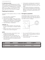
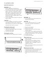
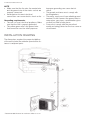
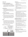
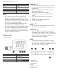
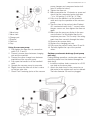
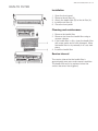
www.electroluxaircomfort.com
www.electrolux.com A
CXH09HL1W
CXH12HL1W
EN SPLIT INVERTER
HEAT PUMP
USER MANUAL
2 www.electroluxaircomfort.com
TABLE OF CONTENTS
Safety precautions...........................................................................................................................3
Description......................................................................................................................................4
Remote control................................................................................................................................4
Cleaning and maintenance..............................................................................................................9
Troubleshooting.............................................................................................................................10
Operation tips...............................................................................................................................11
Installation......................................................................................................................................12
Health filter.....................................................................................................................................20
WE’RE THINKING OF YOU
Thank you for purchasing an Electrolux appliance. You’ve chosen a product that brings with it
decades of professional experience and innovation. Ingenious and stylish, it has been designed
with you in mind. So whenever you use it, you can be safe in the knowledge that you’ll get great
results every time.
Welcome to Electrolux.
Electrolux Central Vacuum Systems
5855 Terry Fox Way
Mississauga, ON, L5V 3E4
Canada
Visit our website:
Get usage advice, brochures, trouble shooter, service information:
www.electroluxaircomfort.com
CUSTOMER CARE AND SERVICE
We recommend the use of original spare parts.
When contacting Service, ensure that you have the following data available.
The information can be found on the rating plate. Model, PNC, Serial Number.
Warning / Caution-Safety information
General information and tips
Environmental information
Subject to change without notice.
www.electroluxaircomfort.com 3
SAFETY PRECAUTIONS
•
Read the manual carefully before operation.
•
Keep the manual for further reference.
•
This appliance is not intended for use by
persons (including children) with reduced
physical, sensory or mental capabilities
or lack of experience and knowledge,
unless they have been given supervision or
instruction concerning use of the appliance
by a person responsible for their safety.
•
Make sure that the unit is properly grounded
to prevent electric shock.
•
Do not attempt to repair the unit yourself to
prevent electric shock or fire. Have the unit
repaired by an authorised service centre.
•
Keep combustible materials at least 1 m
from the unit to prevent fire or explosion.
•
Install the outdoor unit firmly to prevent
personal injury.
•
Children should be supervised to ensure they •
are away from the appliance.
Do not stand on the outdoor unit. Do not
place heavy things on the outdoor unit.
•
If something abnormal occurs (e.g.
•
unpleasant smells of burning), disconnect
•
the unit from the power supply and
contact an authorised service centre. If the
abnormality remains, the air conditioner may •
be damaged or even cause electric shock or
fire.
•
Before cleaning or maintenance, switch off
the unit and disconnect the unit from the
•
power supply. If the unit is connected to a
fuse box, remove the fuse.
•
Do not damage the mains cord or the signal
control wire. If the mains cord or the signal
control wire is damaged, have it replaced by •
a qualified electrician.
Do not block the air inlet or the air outlet.
•
•
Do not splash water on the unit to prevent
electric shock.
Do not operate the unit with wet hands to
prevent electric shock.
Do not insert your hands or objects into the
air inlet or the air outlet.
Do not expose animals or plants directly to
the air flow.
Do not expose yourself to cold air directly for
a long time.
Do not use the unit for any other purpose,
such as preserving food or drying clothes.
•
Do not use an unspecified mains cord to
prevent electric shock or fire.
•
Select the most appropriate temperature to
save electric energy.
•
The unit must be installed according to
national regulations for electrical safety.
Incorrect wiring can lead to over heat or fire
in the cable, the plug or the electrical outlet.
•
Do not keep windows and doors open for a
long time during operation.
•
To change the airflow direction, use remote
control to adjust the horizontal and vertical
airflow direction.
•
Do not dispose this product as unsorted
municipal waste. Collection of such waste
separately for special treatment is necessary
•
Do not switch on and off the unit frequently.
•
If the voltage is too high, electrical elements
will be damaged easily. If the voltage too
low, the compressor will vibrate fiercely
and damage the cooling system or the
compressor. Electrical components cannot
be operated.
4 www.electroluxaircomfort.com
DESCRIPTION
1 Indoor unit
2 Air inlet (indoor unit)
3 Air outlet (indoor unit)
4 Outdoor unit
5 Air inlet (outdoor unit)
6 Air outlet (outdoor unit)
7 Mains cord
8 Remote control
9 Front panel
10 Filter
11 Horizontal louvre
12 Wall pipe
13 Binding tape
14 Connection pipe
15 Drain hose
16 Drain connector
REMOTE CONTROL
The remote control can be used for different
models. Depending on the model, some
functions on the remote control might not be
available.
CAUTION
• Do not drop or throw the remote control.
• Do not pour liquid onto the remote control.
• Do not expose the remote control to direct
sunlight.
• Do not place the remote control in areas
where it is very hot.
NOTE
• Make sure that there are no objects between
the signal transmitter on the remote control
and the signal receiver of the unit.
www.electroluxaircomfort.com 5
Explanation of buttons
No.
Button
Explanation
17
ON/OFF
Press the button to switch on the unit. Press the button again to
switch off the unit.
18
MODE
Press the button to set the operation mode: AUTO, COOL, DRY,
FAN and HEAT. Default setting: AUTO.
In the AUTO mode, the temperature is not shown. In HEAT mode,
the initial value is 28 °C (82 °F). In other modes, the initial value is 25
°C (77 °F).
19
FAN
Press the button to set the fan speed: AUTO, LOW, MEDIUM LOW,
MEDIUM, MEDIUM HIGH and HIGH. Default setting: AUTO. In the
DRY mode, only LOW can be set.
20
UP ^
Press the button to increase the temperature. Keep the button
pressed for two seconds to accelerate the process. Release the
button to set the temperature and send the order that the °C/°F
signal will be displayed constantly.
Temperature range: 16-30 °C (61-86 °F).
In AUTO mode, the temperature cannot be set. If you press the UP
or DOWN button, a beep will sound.
21
DOWN v
Press the button to decrease the temperature. Keep the button
pressed for two seconds to accelerate the process. Release the
button to set the temperature and send the order that the °C/°F
signal will be displayed constantly.
Temperature range: 16-30 °C (61-86 °F).
In AUTO mode, the temperature cannot be set, but the order can be
sent by pressing the button.
22
CLOCK
Press the button to set the clock. If the clock symbol blinks, press
the UP or DOWN button to set the time. Keep the button pressed
for two seconds to accelerate the process. Press the CLOCK button
again to set the clock. The clock symbol stops blinking.
After battery replacement, “12:00 PM” will be shown. If the clock
symbol is visible, the actual time will be shown. If the clock symbol is
not visible, the timer will be shown.
23
LIGHT
Press the button to switch the display of the indoor unit on or off.
Default setting: OFF.
24
TURBO
In COOL or HEAT mode, press the button to enable or disable the
turbo function. If the turbo function is enabled, the turbo symbol will
be shown. Default setting: OFF.
If the turbo function is enabled, the unit will operate at turbo speed
to cool or heat rapidly so that the ambient temperature approaches
the set temperature as soon as possible.
If the operation mode or the fan speed is changed, the turbo symbol
will not be shown.
25
X-FAN
In COOL or DRY mode, press the button to enable or disable the
X-FAN function. If the X-FAN function is enabled, the X-FAN symbol
will be shown. Default setting: OFF.
If the X-FAN function is enabled, the indoor fan will continue operation at low speed for 10 minutes after switching off the unit. This
function prevents the possible condensation on cold parts of the
indoor unit. Press the X-FAN button to switch off the unit during the
process.
If the X-FAN function is disabled, the unit will be switched off immediately.
In AUTO, FAN or HEAT mode, X-FAN is not available.
26
ION-FILTER
Press the button to enable or disable the operation of the health
filter.
6 www.electroluxaircomfort.com
No.
Button
Explanation
27
TIMER ON
Press the button to set the timer function for switching on the unit. If
the TIMER ON symbol blinks, press the UP or DOWN button to set
the time. Keep the button pressed for two seconds to accelerate the
process. Press the button to set the timer. Default setting: 8:00 AM
(12-hour mode). Press the button again to cancel the timer function.
28
TIMER OFF
Press the button to set the timer function for switching off the unit. If
the TIMER OFF symbol blinks, press the UP or DOWN button to set
the time. Keep the button pressed for two seconds to accelerate the
process. Press the button to set the timer. Default setting: 5:00 PM
(12-hour mode). Press the button again to cancel the timer function.
29
SWING-V
Press the button to enable or disable the vertical swing function.
30
SWING-H
Press the button to enable or disable the horizontal swing function.
31
I FEEL
Press the button to enable or disable the I FEEL function. If the I
FEEL function is enabled, the I FEEL symbol will be shown.
If the I FEEL symbol is enabled, the remote control will send the
ambient temperature to the main unit every 10 minutes or when you
press one of the buttons.
32
QUIET
Press the button to enable or disable the QUIET function. If the QUIET function is enabled, the indoor fan operates at ultra-low speed so
that the indoor noise is low.
33
SLEEP
Press the button to select (SLEEP 1, SLEEP 2, SLEEP 3 or SLEEP
CANCEL). Default setting: SLEEP CANCEL.
SLEEP 1
In COOL and DRY mode:
Sleep status after 1 hour of operation: The temperature will increase
by 1 °C.
Sleep status after 2 hours of operation: The temperature will increase by 2 °C.
After this time the unit continues to use the new temperature.
In HEAT mode:
Sleep status after 1 hour of operation: The temperature will decrease by 1 °C.
Sleep status after 2 hours of operation: The temperature will decrease by 2 °C.
After this time the unit continues to use the new temperature.
SLEEP 2
In COOL mode:
If you set a temperature of 16-23 °C, the temperature will increase
by 1 °C every hour. After 3 °C, the temperature will be maintained.
After 7 hours, the temperature will decrease by 1 °C. After this time
the unit continues to use the new temperature.
If you set a temperature of 24-27 °C, the temperature will increase
by 1 °C every hour. After 2 °C, the temperature will be maintained.
After 7 hours, the temperature will decrease by 1 °C. After this time
the unit continues to use the new temperature.
If you set a temperature of 28-29 °C, the temperature will increase
by 1 °C every hour. After 1 °C, the temperature will be maintained.
After 7 hours, the temperature will decrease by 1 °C. After this time
the unit continues to use the new temperature.
If you set a temperature of 30 °C, the temperature will decrease by
1 °C after 7 hours. After this time the unit continues to use the new
temperature.
In HEAT mode:
If you set a temperature of 16 °C, the unit will operate at this temperature.
If you set a temperature of 17-20 °C, the temperature will decrease
by 1 °C every hour. After 1 °C, the temperature will be maintained.
www.electroluxaircomfort.com 7
No.
Button
Explanation
If you set a temperature of 21-27 °C, the temperature will decrease
by 1 °C every hour. After 2 °C, the temperature will be maintained.
If you set a temperature of 28-30 °C, the temperature will decrease
by 1 °C every hour. After 3 °C, the temperature will be maintained.
SLEEP 3
The user-defined behaviour mode. The time on remote control will
show “1hour”. The temperature to use after 1 hour will blink.
Press the UP and DOWN buttons to set the desired temperature.
Press the TURBO button again to confirm.
The value “1hour” will increase to the value “2hours”, “3hours” or
”8hours”. In each step the corresponding temperature will blink.
Repeat the above (2 3) operation for the “2hours”, “3hours” and
”8hours” steps.
Sleep3: Display the set temperatures:
Select SLEEP 3 without changing temperature. Press the TURBO
button to confirm.
Note: The above setting or enquiry procedure terminates if no button is pressed for 10 seconds. The ON/OFF button, the MODE
button and the SLEEP button also terminate the setting or enquiry
procedure.
General operation
Special functions
1. Disconnect the unit from the power supply.
2. Press the ON/OFF button to start the unit.
3. Press the MODE button to set the operation
mode.
4. Press the UP and DOWN buttons to set the
temperature. (Note: It is unnecessary to set
the temperature in AUTO mode.)
5. Press the FAN button to set the fan speed.
6. Press the SWING-H and SWING-V buttons
to set the swing.
AUTO mode
The temperature will not be displayed. The unit
automatically sets the operation mode.
Optional operation
1. Press the SLEEP button to enable or disable
the sleep mode.
2. Press the TIMER ON and TIMER OFF buttons to enable or disable the timer function.
3. Press the LIGHT button to turn on or to turn
off the display of the indoor unit.
4. Press the TURBO button to enable or disable the turbo function.
Locking/unlocking the remote control
Simultaneously press the SWING-V button and
the ION-FILTER button to lock or unlock the remote control. If the remote control is locked, the
LOCK symbol will be shown. Press any button
to make the LOCK symbol blink 3 times and unlock the remote control. If the remote control is
unlocked, the LOCK symbol will not be shown.
Celsius (°C) ~ Fahrenheit (°F)
If the unit is switched off, simultaneously press
the SWING-H button and the ION-FILTER button to switch between Celsius (°C) and Fahrenheit (°F).
Energy-saving function
In COOL mode, simultaneously press the IONFILTER button and the CLOCK button to enable or disable the energy-saving function. The
display shows ”SE”.
8 www.electroluxaircomfort.com
8 °C heating function
In HEAT mode, simultaneously press the IONFILTER button and the CLOCK button to enable
or disable the 8 °C heating function. The display
shows ”8 °C” (”46 °F”). The unit starts to heat
when the temperature drops below 8 °C. Fan
Speed will be AUTO and cannot be changed.
Replacing the batteries
The remote control operates with two 1.5V AAA
batteries.
1. Open the battery compartment.
2. Remove the old batteries.
3. Insert the new batteries. Make sure that the
positive (+) and negative (-) markings on the
batteries match the positive (+) and negative
(-) markings on the battery compartment.
4. Close the battery compartment.
•
•
If the remote control transmits a signal, the
transmitting symbol will blink for 1 second.
The bell will ring if the main unit receives the
signal.
If the remote control does not operate normally, remove the batteries and insert them
again 30 seconds later. If the remote control
still does not operate normally, replace the
batteries.
Emergency operation
If the remote control cannot be used, use the
AUTO/STOP button on the main unit. The unit
will operate in AUTO mode. The temperature or
fan speed cannot be changed.
CAUTION
• Always use new batteries of the same type.
Do not use old batteries or different batteries
types.
• Remove the batteries when the remote control will not be used for a long time.
NOTE
• Operate the remote control within its transmitting and receiving range.
• Operate the remote control at least 1 m
away from your TV set or stereo sound set.
• Aim the remote control at the receiver of the
main unit to improve the receiving sensitivity
of the main unit.
Mode
AUTO
AUTO
AUTO
Model
Cooling only
Heat pump
Heat pump
1. Press the AUTO/STOP button to switch on
the unit. The unit automatically sets the operation mode.
2. Press the AUTO/STOP button again to
switch off the unit.
Temperature setting
25 °C (COOL, FAN)
25 °C (COOL, FAN)
20 °C (HEAT)
Fan speed
AUTO
AUTO
AUTO
www.electroluxaircomfort.com 9
CLEANING AND
MAINTENANCE
WARNING
• Before cleaning and maintenance,
disconnect the unit from the power supply.
• Do not immerse the unit in water or other
liquids. If the unit is immersed in water or
other liquids, do not remove the unit with
your hands. Immediately disconnect the
unit from the power supply. If the unit is
immersed in water or other liquids, do not
use the unit again.
• Do not splash water on the unit to prevent
electric shock.
CAUTION
• Do not use aggressive liquids (e.g. thinner
or gasoline) to clean the unit. Clean the
unit using a soft, dry cloth or a cloth slightly
moistened with water or cleaner.
Cleaning the front panel
1. Remove the front panel.
2. Clean the front panel using a cloth slightly
moistened with water.
3. Install the front panel.
Cleaning the air filter
The air filter must be cleaned every 3 months.
WARNING
• Do not touch the fin of the indoor unit to
prevent personal injury.
CAUTION
• Do not use water above 45 °C to clean
the air filter to prevent deformation or
discolouration.
1. Open the front panel.
2. Remove the air filter.
3. Remove dust from the air filter using a
vacuum cleaner.
4. If the air filter is dirty, clean the air filter with
warm water and a mild detergent. Allow the
air filter to dry naturally in a cool, dark place.
5. Install the air filter.
6. Close the front panel.
Check before use
• Make sure that nothing obstructs the air inlet
or the air outlet.
• Make sure that the installation stand of
the outdoor unit is not damaged. If the
installation stand is damaged, consult a
qualified technician.
• Make sure that the batteries are inserted into
the remote control.
Maintenance after use
• Disconnect the unit from the power supply.
• Clean the filters and the housings of the
indoor unit and the outdoor unit.
• Remove any obstructions from the outdoor
unit.
10 www.electroluxaircomfort.com
TROUBLESHOOTING
CAUTION
• The unit is not user-serviceable. Do not
attempt to repair the unit yourself to
prevent electric shock or fire. Have the unit
repaired by an authorised service centre.
The following checks can save you time
and money before consulting an authorised
service centre.
Problem
Solution
The unit does not operate.
The unit does not operate if it is switched on immediately
after switching off the unit. After switching off the unit,
wait for approximately 3 minutes before switching on the
unit.
Odours are emitted.
Some odours may be emitted from the indoor unit as the
result of room smells (furniture, tobacco, etc.) which have
been taken into the unit. If the odours persist, contact an
authorised service centre.
Water-flowing noise.
The water-flowing noise is the refrigerant flowing inside
the unit.
Mist is emitted in COOL mode.
During cooling operation, mist may be emitted from the
indoor unit due to high room temperature and humidity.
The mist will disappear if the room temperature and
humidity decrease.
Cracking noise.
The cracking noise is the sound of friction caused by
expansion and/or contraction of the front panel or other
parts due to the change in temperature.
The unit cannot be started.
Is the unit disconnected from the power supply?
Is the mains plug loose?
Is the circuit protection device tripped off?
Is the voltage higher or lower? (tested by professionals)
Is the timer function used correctly?
The cooling/heating effect is poor.
Is the temperature set correctly?
Is the air inlet or the air outlet blocked?
Is the air filter dirty?
Is the window or the door open?
Is a low fan speed set?
Are there heat sources in the room?
The remote control does not work.
Is there any magnetic or electrical interference near the
unit? If yes, remove and reinsert the batteries.
Is the remote control within its transmitting and receiving
range without any obstructions? If necessary, replace the
batteries.
Is the remote control damaged?
Water leakage in indoor unit.
The room humidity is high.
Condensing water over cools.
The drain hose is loose.
Water leakage in outdoor unit.
In COOL mode, water condensate is generated around
the pipes and connection joints.
In HEAT mode, the water on the heat exchanger drips
out.
In defrost mode, the thawed water flows out.
Noise from indoor unit.
The noise emitted when the fan or compressor relay is
switched on or off.
www.electroluxaircomfort.com 11
Problem
Solution
If the defrost mode is started or stopped, you will hear
the sound of refrigerant cooling in the reverse direction.
The indoor unit cannot blow air.
In HEAT mode, when the temperature of the indoor heat
exchanger is low, the airflow is stopped within 2 minutes
in order to prevent cold air.
In HEAT mode, when the outdoor temperature is low
or the outdoor humidity is high, frost will be formed
on the outdoor heat exchanger. The unit will defrost
automatically and the indoor unit will stop blowing air for
3-12 minutes.
In DRY mode, the indoor fan will stop blowing air for
3-12 minutes in order to avoid condensing water being
vaporised again.
In defrost mode, water or vapour may be emitted.
Moisture on air outlet.
If the unit operates at high humidity for a long time,
moisture will be generated on the grill of the air outlet.
C5: Malfunction of connector jumper.
Check if the connector jumper contacts properly. If
necessary, replace the old circuit board with a new circuit
board.
F1: Malfunction of indoor ambient temperature sensor.
Check if the indoor room temperature sensor is
connected properly.
F2: Malfunction of evaporator temperature sensor.
Check if the evaporator temperature sensor is connected
properly.
There is harsh sound during operation.
Immediately stop operation, disconnect the unit from the
power supply and contact an authorised service centre.
Strong odours are emitted during operation.
Immediately stop operation, disconnect the unit from the
power supply and contact an authorised service centre.
Water is leaking from the indoor unit.
Immediately stop operation, disconnect the unit from the
power supply and contact an authorised service centre.
The air switch or protection switch often interrupts power Immediately stop operation, disconnect the unit from the
supply.
power supply
Water or other liquid is splashed into the unit.
Immediately stop operation, disconnect the unit from the
power supply and contact an authorised service centre.
Mains cord and mains plug are overheated.
Immediately stop operation, disconnect the unit from the
power supply and contact an authorised service centre.
OPERATION TIPS
Cooling operation
Heating operation
Air conditioners absorb heat from indoor and
transmit the heat to the outdoor unit in order to
decrease the room temperature. The cooling
capacity will increase or decrease according to
the outdoor temperature.
Air conditioners absorb heat from outdoor and
transmit the heat to the indoor unit in order to
increase the room temperature. The heating
capacity will increase or decrease according to
the outdoor temperature.
Anti-freezing function
Defrosting
If the unit is in COOL mode and in a low ambient • If the outdoor temperature is low and the
temperature, frost will be formed on the heat
outdoor humidity is high, frost will form on
exchanger of the indoor unit. If the temperature
the outdoor unit during extended operation.
of the heat exchanger decreases below zero,
The heating capacity will decrease. The unit
the compressor will stop operation to protect
may stop operation during defrosting.
the unit.
• During defrosting, the fan motors of the
12 www.electroluxaircomfort.com
•
•
indoor unit and outdoor unit will stop
operation.
During defrosting, the indoor indicator
flashes and the outdoor unit may emit
vapour. This is normal operation to remove
frost from the heat exchanger of the outdoor
unit.
After defrosting, the heating operation will
resume automatically.
Anti-cold air function
•
In HEAT mode, the temperature reaches the
set value and the compressor has stopped
operation for 1 minute.
Operating temperature range
The operating temperature range for coolingonly units is 16-48˚C. The operating temperature
range for heat-pump units is -20-(+24)˚C.
Tips for energy saving
In HEAT mode, the indoor fan will not operate in •
order to prevent cold air from blowing out if the
indoor heat exchanger does not reach a certain
temperature in one of the following situations:
•
• when the heating operation starts;
• when the defrosting operation is finished;
• when heating at low temperature.
•
Gentle breeze
Do not overcool or overheat. Setting the
temperature at a moderate level helps energy
saving.
Cover windows with a blind or a curtain.
Blocking sunlight and air from outdoor is
favourable for cooling.
Clean air filters every two weeks. Clogged air
filters lead to inefficient operation and energy
waste.
The indoor unit may blow gentle breeze and the
horizontal louvre rotates to a certain position in
one of the following situations:
• In HEAT mode, the compressor does not
start operation after switching on the unit.
Tips for relative humidity
Indoor side (°C)
Outdoor side (°C)
Max. cooling
32
48
Min. cooling
21
16
Max. heating
27
24
Min. heating
20
-20
•
If the unit is operated in an area with a
relative humidity of more than 80% for a long
time, condensate may drip from the indoor
unit.
INSTALLATION
Installation notes
•
•
•
•
•
Not following the instructions can cause
personal injury and/or property damage.
Not following the instructions can cause the
unit to fail.
Let the unit be installed by an authorised
service centre.
Let the unit be installed in compliance with
local and governmental regulations.
Let the unit be installed according to the
instructions from this manual.
•
•
•
•
•
First contact an authorised service centre
before relocating an already installed unit
Disconnect power before working on the
unit.
Let the mains cable be repaired by an
authorised service centre or qualified
technician for units with Y-attachment.
The mains plug must remain accessible after
installation.
Keep sufficient distance between the
interconnection cable and the refrigerant
www.electroluxaircomfort.com 13
•
•
circuit because the circuit operating
temperature is high.
The pipes connecting the indoor and
outdoor unit are not included in the unit.
The outdoor unit is powered by the indoor
unit.
Installation site
Do not install the unit in areas with:
• strong heat sources;- vapours or flammable
gasses;
• contamination with oil particles;
• high frequency electromagnetic equipment
(e.g. welding equipment or medical devices);
• high salinity (e.g. close to coastal areas);
• sulphuric gas (e.g hot water springs);
• poor air quality.
•
•
•
•
•
•
•
•
•
Indoor unit
• Maintain the minimum installation distances
specified in this document. Do not block the
air inlet or the air outlet.
• Do not use the unit in places with extremely
high humidity.
• Install the indoor unit out of reach of children
• The wall must be strong enough to support
the weight and vibration of the unit.
• Install the indoor unit at least 50 cm above
the floor surface.
• Leave sufficient space for cleaning and
maintenance.
• The air filter should remain accessible.
• Leave at least 1 m distance between the unit
and other electrical appliances.
• Install the indoor unit in a place where the
condensate water can be easily drained
• Install at a location protected from direct
sunlight.
Outdoor unit
• Maintain the minimum installation distances
specified in this document.
• Do not block the air inlet or the air outlet
• Install the outdoor unit out of reach of
children.
Install the outdoor unit where there is
sufficient ventilation.
Install the outdoor unit where produced
noise and airflow will not disturb neighbours
or animals.
Install the outdoor unit in a dry place.
Install the outdoor unit in a place not
exposed to direct sunlight or strong wind.
Install the unit in a place that supports the
weight and vibration of the unit.
The height difference between the indoor unit
and the outdoor unit must be less than 5 m.
The length of the connecting pipes must be
less than 10 m.
Leave sufficient space for cleaning and
maintenance.
The outdoor unit is powered by the indoor
unit.
Safety precautions for electrical appliances
• Use a dedicated mains circuit.
• The unit must be properly grounded.
• Install a Residual-current device (RCD) to
protect against personal injury in case of
leakage currents.
• Use an all pole disconnection switch with
a contact separation of at least 3 mm in
all poles in fixed wiring. For models with a
mains plug, make sure that the mains plug is
within reach after installation.
• The installation must comply with local
electrical safety regulations and with other
relevant local regulations
• The unit must be installed in accordance with
national wiring regulations.
• Do not subject the mains cable to force.
• The distance between the unit and heat
sources is at least 1.5 m.
• Use an air switch. The air switch must have
functions for magnetic tripping and heat
tripping to prevent short circuit and overload.
The suitable capacity is specified in the
following table.
Air conditioner (Btu)
Air switch capacity
09-12K
16A
14 www.electroluxaircomfort.com
NOTE
• Make sure that the live wire, the neutral wire
and the ground wire in the mains socket are
properly connected.
• Inadequate or incorrect electrical
connections can cause electric shock or fire.
•
•
Grounding requirements
• The unit is a type I electrical appliance. Make
sure that the unit is properly grounded.
•
• The yellow-green wire is the ground wire
that cannot be used for other purposes.
INSTALLATION DRAWING
The dimensions required for proper installation
of the unit include the minimum permissible distances to adjacent parts.
* Recommended distance for maximum airflow is 15 cm.
Improper grounding can cause electric
shock.
The ground resistance must comply with
local regulations.
The mains supply must have reliable ground
terminal. Do not connect the ground wire to
water pipes, gas pipes, contamination pipes
or other possible unsafe places.
Fuses must comply with the prescribed
model and rating printed on the fuse cover or
circuit board.
www.electroluxaircomfort.com 15
Indoor unit
CAUTION
• Check the wiring to make sure that there is
no short circuit. Incorrect wiring can cause
Installing the mounting plate
malfunction.
1. Install the mounting plate horizontally.
1. Open the front panel.
2. Fix the mounting plate to the wall with
screws. Make sure that the mounting plate is 2. Remove the wiring cover.
fixed firmly enough to support approximately 3. Fix the mains cord to the terminal board (as
shown).
60 kg. The weight must be evenly shared by
4. Guide the mains cord through the hole at the
each screw.
back of the indoor unit.
5.
Install the cord anchorage and wiring cover.
Drill piping hole
6. Close the front panel.
1. Slant the piping hole (Ø 55 mm) on the wall
slightly downward to the outdoor side.
2. Insert the piping-hole sleeve into the hole to NOTE
• The electrical wiring between the indoor unit
prevent damage to the connection piping
and the outdoor unit must be connected by
and wiring.
a qualified electrician.
•
Tighten the terminal screws tightly.
Installing the drain hose
• After tightening the screws, pull the wire
1. Connect the drain hose to the outlet pipe
slightly to confirm whether it’s firm or not.
of the indoor unit. Bind the joint with rubber
•
Make sure that the electrical connections are
belt.
properly grounded to prevent electric shock.
2. Put the drain hose into the insulating tube.
•
Make sure that the wiring connections are
3. Wrap the insulating tube with wide rubber
secure and that the cover plates are properly
belt to prevent the insulating tube from shiftmounted to prevent electric shock.
ing. Slant the drain hose slightly downward
for smooth drainage of the condensate
Installing the indoor unit
water.
The piping can be output from the right, the right
rear, the left or the left rear.
NOTE
1. When routing the piping and wiring from the
• The insulating tube must be connected relileft or right of indoor unit, cut off the tailings
ably with the sleeve outside the outlet pipe.
from the chassis when necessary.
The drain must be slanted downward slightly
2.
Remove the piping from the body case.
without distortion, bulge or fluctuation. Do
3. Wrap the piping, the mains cords and the
not put the outlet of the drain hose in water
drain hose with the tape.
to prevent the drain hose from freezing.
4. Guide the piping, the mains cords and the
drain hose through the piping hole.
Electrical wiring indoor unit:
5. Firmly hang the mounting slots of the indoor
unit on the upper hooks of the mounting
plate.
6. The installation site must be at least 50 cm
above the floor surface.
No.
Colour
1
Blue (Neutral)
2
Black
3
Brown
4
Yellow (Ground)
Installing the connection pipe
1. Align the centre of the piping flare with the
related valve.
2. Screw in the flare nut by hand and then tighten the nut with spanner and torque wrench.
Refer to the following table.
16 www.electroluxaircomfort.com
Hex nut diameter (mm)
Tightening torque (Nm)
Ø6
15-20
Ø 9.52
30-40
Ø 12
45-55
Ø 16
60-65
Ø 19
70-75
NOTE
• First connect the connection pipe to the
indoor unit and then to the outdoor unit.
Handle the piping bending with care. Do not
damage the connection pipe. Firmly tighten
the joint nut to prevent leakage.
• The pipes connecting the indoor and outdoor unit are not included in the unit.
• In case the connective pipe length is longer
than 7.5m charge the unit with additional
refrigerant. Add 20g/m of R410A for models with a capacity of less than 6500W. Add
50g/m for the other models.
Outdoor unit
CAUTION
• Check the wiring to make sure that there is
no short circuit. Incorrect wiring can cause
malfunction.
1. Remove the handle (x2) on the right side
plate of outdoor unit.
2. Remove mains cord anchorage.
3. Connect the mains cord to the terminal
board.
4. Lock the position of the cord with wire
clamps.
5. Check for improper connections.
6. Reinstall the handle.
NOTE
• Check for free space between the connection and the lock positions.
CAUTION
• Open the stem of the packed valve until it
hits against the stopper. Do not try to open
it further. Close the stem of the packed valve
with a special tool. Close the cap of the
packed valve with a spanner.
Electrical wiring
NOTE
• The outdoor unit has two outlets, the low
side outlet and the high side outlet. Only the
low side outlet contains a charging port. The
low side outlet is shown below.
No.
Colour
1
Blue (Neutral)
2
Black
3
Brown
4
Yellow (Ground)
1 Indoor unit
2 Outdoor unit
3 Refrigerant
4 Gas
5 Packed valve
6 Half union
www.electroluxaircomfort.com 17
1 Valve body
2 Valve stem
3 Charge port
4 Stopper
5 Flare nut
6 Cap
Using the vacuum pump
1. Fully tighten the flare nuts at connection
point A, B, C and D.
2. Connect vacuum hose between charging
port and the manifold.
3. Connect the other charge hose between
manifold and the vacuum pump.
4. Fully open the handle Lo of the manifold
valve.
5. Operate the vacuum pump to evacuate.
6. Slightly loosen the flare nut of the Lo valve
on the gas pipe side.
7. Check if air is entering (noise of the vacuum
pump changes and compound meter indicates 0 instead of minus).
8. Tighten the flare nut.
9. Make evacuation for 15 minutes or more and
check that the compound meter indicates
-7.6 x 10⁵ μmHg (-1x10⁵ Pa) (-0,7Bar).
10. Fully close the handle Lo of the manifold
valve and stop the operation of the vacuum
pump.
11. Turn the stem of the packed valve B about
45° counterclockwise for 6~7 seconds after
the gas comes out, then tighten the flare nut
again.
12. Make sure the pressure display in the pressure indicator is a little higher than the atmosphere pressure. This to verify if the refrigerant does flow correctly through the tubes.
13. Remove the vacuum hose.
14. Replace the charging port cap.
15. Fully open the packed valve stems B and A.
16. Securely tighten the cap of the packed
valves.
Outdoor condensate drainage (heat-pump
unit only)
During heating operation, condensate water and
defrosting water must be drained through the
drain hose.
1. Install the outdoor drain connector in a Ø 25
mm hole on the base plate.
2. Attach the drain hose to the connector so
that water in the outdoor unit can be drained.
The hole diameter 25 must be plugged.
18 www.electroluxaircomfort.com
Check after installation
Items to be checked
Possible malfunction
Has the unit been affixed firmly?
The unit may drop, shake or emit noise.
Have you done the refrigerant leakage test?
Insufficient cooling or heating.
Is the thermal insulation sufficient?
Condensation.
Is the water drainage satisfactory?
Water leakage.
Is the voltage in accordance with the rated voltage on the Electrical malfunction or damage to the unit.
nameplate?
Is the electrical wiring or piping connection installed
correctly and securely?
Electrical malfunction or damage to the parts.
Has the unit been securely grounded?
Electrical leakage.
Is the mains cable as specified?
Electrical malfunction or damage to parts.
Is the air inlet or the air outlet blocked?
Insufficient cooling or heating.
Is the length of the connection pipes and the refrigerant
capacity as specified
Inaccurate refrigerant capacity.
Is the length of the connection pipes and the refrigerant
capacity as specified
Inaccurate refrigerant capacity.
Operation test
Before operation test
• Do not connect the unit to the power supply
before the installation is completed.
• The electrical wiring must be connected correctly and securely.
• The cut-off valves of the connection pipes
must be opened. Refer to the section “Vacuuming and leakage test”.
• The unit must be cleaned thoroughly.
Operation test method
1. Connect the unit to the power supply.
2. Press the ON/OFF button to switch on the
unit.
3. Press the MODE button to set the operation
mode and check whether the operation is as
expected.
www.electroluxaircomfort.com 19
HEALTH FILTER
Installation
1.
2.
3.
4.
5.
Open the front panel.
Remove the air filter (A).
Attach the health filter (B) to the air filter (A).
Install the air filter (A).
Close the front panel.
Cleaning and maintenance
1. Remove the health filter.
2. Remove dust from the health filter using a
vacuum cleaner.
3. If the health filter is dirty, clean the health filter
with warm water and a mild detergent. Allow
the health filter to dry naturally in a cool, dark
place.
4. Install the health filter.
Service interval
The service interval for the health filter is
approximately one year under normal condition.
The health filter must be replaced when the
surface becomes black (green).
20 www.electroluxaircomfort.com
Distributed by: