1
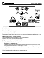
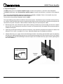
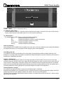
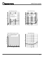
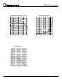
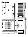
14B-SST
POWER AMPLIFIER
OWNER’S MANUAL
UPDATED 2006-10-26
14B-SST Series Amplifier
Table of Contents
General Introduction Description
InstallationandVentilation
Page1
Rear Panel Input Settings/Connections
SettingInputSelectorSwitch
BalanceInputConnectorConfiguration
SettingInputSensitivity
Page2
Output Binding Posts Power
Page3
Control Panel MasterCircuit-Breaker
ACPowerInput
Local/AutoSwitch
Page4
Front Panel Description
LEDIndicator(Power-upSequence)
LEDIndicator(OperatingConditions)
Typical Performance Graphs Page5
Page6-7
External Dimensions Page8
Technical Specifications
Page9
Important Safety Instructions & Warranty Information
BackCover
14B-SST Series Amplifier
Introduction
Thankyouforchoosingthe14B-SST Stereo Power Amplifier.
Brystonwelcomesanysuggestionsyoumayhave,orcommentsregardingtheoperationofyouramplifier.Weconsider
you,ourcustomer,tobeBryston’smostimportantresource,andyouropinionisverymuchappreciated.
Description 14B-SST
The14B-SSTisadualchannel600Wattaudiopoweramplifier.The14BSSTcanacceptabalanced(3-pinXLRconnector)orsingleendedinput(RCAorphonoconnector)andcanbesettoagainof29dB(sensitivity=1V)or23dB(sensitivity
=2V).The14B-SSTincludes‘softstart’powercontrolcircuitrytoeliminatehighinrushcurrentswhenA/Cpowerisapplied.
Thepoweruporturn-onofthe14B-SSTmaybeactivatedbyaremotecontrolvoltage4vto12vacordc.
Warranty ( see back page for details )
Shipping Box & Packing Material
Pleasekeeptheoriginalshippingboxandallpackingmaterial.Thiswillensuretheamplifierisprotectedinfuturetransport.
Intheunlikelyeventyouhaveaproblemandmustreturnitforserviceyou mustusetheproperpackingmaterial.Shipthe
amplifieronlyintheoriginalpackingmaterial,astheunitisnotinsurablebycarriersotherwise.
Installation ( see rack mounting section if applicable )
Ventilation. The most important installation consideration is ventilation. The 14B-SST amplifier is convection cooled.
Unrestricted air-flow across the 14B-SST heat sinks is a must. For this reason do not install anything directly above it.
Allow3.5’(2u)to5”(3u)inchesofspaceaboveandtothesidesofthisamplifier.Donotinstalldirectlyaboveotherheat
generatingequipment.Shouldyourinstillationconditionsbeconstricted,thenadditionalforcedair-coolingmaybenecessary.Brystoncanprovideanoptionalfanpackageifrequired.Thermalshutdownduringoperationindicatesinsufficient
airflow,andaremedymustbefoundforcoolingtheamplifier.Provideaminimum6”spacetotherearoftheamplifierfor
ventilationanddressingcablestoandfromtheamplifier.
Never operate the amplifier in a vertical position.
Wiring the 14B-SST amplifier ( also see rear panel description )
Speaker wiresshouldbeasshortaspractical.Usequalitywire,andifrunsaremorethan3metersuseatleast12gage
wire.Thespeakerbindingpostswillacceptwireupto3gageinsize.Brystonoffersspeakercablesandampinterconnects
foryourapplication.Checkourwebsiteunderproducts/cables(www.bryston.ca)formoreinformation.
A/C power
Beforeplugginginthepowercordbesureyour14B-SSTamplifierisspecifiedforthecorrect AC voltageforyourlocality.
Thevoltageislistedonthelabelfoundattheupperrightoftherearpanel.Thecircuitfeedingthe14B-SSTshouldbesufficientsoasnottocausethecircuitbreakertotrip(15ampmin.).Note:the14B-SSTwhendeliveringmaximumpowerinto
a4ohmload,willconsumealltheavailablepowerinanormalhouseholdcircuit,thereforeadedicatedelectricalcircuitmay
benecessarywiththissituation.Neverliftthesafetygroundtotheamplifiernorremovethegroundpinfromtheplug.
1
14B-SST Series Amplifier
Rear Panel Input / Output Connections
Figure1
1. Input Select Switch.
TheINPUTSELECTswitchgivestheusertheoptionofswitchingbetweeneitherbalancedinputorsingleendedinput.
2. Input Sensitivity Selection.
Thisswitchchangesthegainoftheamplifier.
● The1vsettinghasagainof29dB
● The2vsettinghasagainof23dB
Theoptimumgainsettingwilldependuponthesourcepre-ampoperatinglevel,andorpersonalpreference.
Usethe2vsettingwithanysystemswherethevolumecontrolrotationislimitedtothebottomhalfofthecontrolorless.
3. Balanced Input connector. (input imp 58K each leg)
Thisinputconnectoracceptsstandard‘XLR’or1/4”Phonejack(Tip-Ring-Sleeve).
Usequality,100%shieldedcableswithgold platedconnectors.
4. Single Ended Input. ( Un-balanced input) ( Imp. 50K )
Thisinputconnectoracceptsstandard‘RCA’or‘Phono’connectors.
Usequality,100%shieldedcableswithgold platedconnectors.
Balanced input Vs Single ended input:
Thebalancedinputrequiresabalancedpre-ampsource.Balancedsystemsprovidenoiserejectionfromexternal
electricalinterference,socablelengthcanbeverylong(50morlonger).
Thesingleendedorunbalancedinputisprovidedforpre-ampswithoutbalancedoutput.Single-endedcablesshould
bekeptto20’(7m)orless.Ingeneralneveruselongercablesthannecessary,nevercoilexcesscablelength,and
keepsignalwiresawayfromACpowerorspeakercables.
5. Level Control. (Pro models only)
Thelevelcontrolwillattenuatetheinputsignallevelfrom0dBthrough-14dB.
2
14B-SST Series Amplifier
6. Output binding posts.
TheREDbindingpostisthein-phase amplifier output.Connecttothispostthe(+)terminalontheloudspeaker.
TheBLUEbindingpostistheinverted-phase amplifier output.Connecttothispostthe(-)terminalontheloudspeaker.
Note:At no time shouldeither output be connected to a ground, or chassis.Failureoftheamplifiermayresult.
Neverconnecteitheroutputinparallelwithanotheramplifier.
Theminimumrecommendedloudspeakerloadis4 ohms.
TheOutputbindingpostsprovidethreedifferentinterconnectoptions.Combinationsmaybeusedwhenbi-wiring.Seefigure2below.Cablesshouldbekeptasshortaspracticalandshouldneverbeterminatedwithconnectorsthatmaybecome
confusedforACpowerconnectors.Cablesshouldbedressedawayfrominputandpowercables.
● Banana plugsofferaquickdisconnectoption.Beforeinsertingabananaplugintothebindingpostbesuretotighten
thepostnuttoavoidrattlingandtoprovidefullinsertionofthebananaplug.Goldplatedlockingbananaplugsare
availablefromBryston.
● S
pade lugsprovidehighcontactareaandsecurefastening.Lugsshouldbegoldplated.Seediagramfordetails.Post
diameteris5/16’(8mm),lugwidth5/8”(16mm).GoldplatedspadelugsareavailablefromBryston.
● Stripped bare wireupto3gagecanbeinsertedthroughtheholeinthebindingpostandheldinplacebytightening
thepostknob.Additionaltighteningpressurecanbeachievedusingacoinintheslotsoftheknob.Donotovertighten
orthebindingpostmaybecomedamaged.Notethatcopperwireismalleableandmayrequirefurthertighteningafter
theinitialinstallation.
SPADE
LUG
Spadelugdimensions
BARE
WIRE
5/8”
5/16”
BANANA
PLUG
3
14B-SST Series Amplifier
Power Control
(refer to figure 1 on page 2)
7. Master circuit - breaker.
The14B-SSTamplifierusesamagnetic-tripcircuitbreakertoprotecttheamplifier.
Thisswitchshouldbe‘OFF’duringinstallation.Whenswitched‘OFF’
AllA/Cpowerisremovedfromtheamplifier,includingstandbypower.
Thecircuitbreakerisnotthepowerswitchandshouldbeswitchedtoandleft‘ON’aftertheinstallationiscomplete.Use
the14B-sstfrontpanelpowerswitchoranexternalcontrolvoltagetoPower-uporPower-downtheamplifier.
Shouldthebreakertrip,lowerorremovetheamplifierinputsignal(alsoseesection9below).Switchthebreakertothe
‘ON’position.Thenpowertheunitupnormally.
The circuit breaker must be ‘ON’ at all times for the 14B-SST amplifier to operate.
8. AC power input.
Ontherearpanelisprovidedahighcurrentplugforthepowercordreceptacle.Checkthatthevoltageratingonthelabel
(item12infigure1,page2)conformswithyourlocality.Withthecircuitbreaker‘OFF’insertthepowercordintothe14BSSTamplifier,thenplugtheotherendtoanappropriateA/Cpoweroutlet.Switchthecircuitbreakertoonandobservethe
LEDlabeled"LineVoltageStatusIndicator".
9. LINE VOLTAGE STATUS INDICATOR
ThisLEDwillbeonanytimetheamplifierispluggedintoasourceofelectricalpower.NormallytheLEDwillbegreen,
anditmustbegreenfortheamplifiertopoweron.
Shouldtheamplifiernotpoweron,andtheLEDisflashing,removethepowercordfromtherearoftheamplifierand
waitafewsecondsthenplugthepowercordbackin.
ShouldtheLEDbered,aconditionexistspreventingtheamplifierfrompoweringup.
Reasons–theappliedelectricalpowerisoutsidetheoperatingrange–120vunitconnectedto230v–Checktheelectricalratingslabelontherearpaneltoseeifthevoltageiscorrectforyourlocation.Otherwiseconsultyourdealerorcall
thefactory.
10 & 11: External control voltage power up ( Local/External switch & Interface Connector)
● Topower-uptheSSTamplifierusinganexternalcontrolvoltage:
1) Supplya4vto12vA/CorDCcontrolvoltagetothe‘IN’terminalsofconnector(10).
2) Usepairedwireof22to18gagesufficientinlengthbetweenthesourcedeviceandtheSSTamplifier.
3) Setslideswitch(item11infigure1,page2)to“External”.Theamplifierwillnowpower-uponlywhenthecontrol
voltageispresent(on).
Immediatelyfollowingpowerup,thecontrolvoltagewillappearatthe’OUT’terminalsoftheinterfaceconnector
(item10onfigure1,page2,alsoseebelow)forthecontrolofotherequipment.Theremovalofthecontrolvoltage(0v)causestheamplifiertoturn‘off’andthecontrolvoltageatthe‘OUT’terminalsisinterrupted.
●Inthe"Local”setting:
The14B-SSTamplifierwillignorethecontrolvoltage,andpoweruponlybyusingthefrontpanel‘SSTPOWER’
switch,orasinsection3above. Ifacontrolvoltageispresentatthe‘IN’terminalsitwillstillbeavailableatthe
‘OUT’terminalsafterthepower-upsequence.
Note:
The ‘OUT’ terminals are connected to the ‘IN’ terminals once the 14B-SST amplifier has powered-up. The control current is determined by the source equipment. The carrying current of
the ‘OUT’ relay is 2 amps. The 14B-SST control circuitry itself draws less than 2 mA from the
control current when operating.
4
14B-SST Series Amplifier
14
13
FRONT PANEL (refer to illustration above)
13. ‘14B-SST’ power switch
Thefrontpanellabel‘14B-SST’,isapushonpushoffswitchusedtoapplyorremoveAClinepowertothesoftstart
circuitry.(Note:therearcircuitbreakermustbeonfortheamplifiertopower-up)
14. LED Indicators
The14B-SSThasanLEDindicatortomonitorthefollowingconditions:
Unlit - indicatestheamplifieristurnedoff.
Red - indicatestheamplifierismuted(inapower-upsequence)
GReen -indicatestheamplifieroperationisnormal.
FlashinG Red - indicatestheamplifierclipping.
ORanGe -
indicateschannelthermalshutdown.
Power up sequence
Afterpushingthe'SSTPOWER'switch,theLEDwillturnfromunlittored(mute).Whenthepowersupplyhasstabilized
theamplifierwillcomeoutofmuteandtheLEDwillchangetogreen(normaloperation).
Unlit LED ( power off )
The14B-SSTLEDwhenunlitindicatesnoA/Cmainspowerispresentandtheamplifierprobablyneedsonlytobe
poweredonortherearpanelcircuitbreakerisswitchedoff.Shouldtheamplifiernotpoweronwhenthepowerswitchis
pushedseetheinstallationinstructions.
Clipping ( flashing red )
Clippingoccurswhenthechanneloutputlevelnolongercanfollowthelevelincreaseattheinput(Over-driveninput
condition).Whenthe14B-SSTisdrivenintoclippingtheLEDwillchangefromgreentoredthenbacktogreenwhenthe
levelisreduced(FlashingRed).Momentaryclippingcanbetolerated,howeveritindicatesthatmaximumun-distorted
powerhasbeensurpassedandpotentialspeakerdamagemayresultifoverloadconditionspersist.Anyamplifierthatis
constantlyoperatedintoclippingindicatesamorepowerfulamplifierisneededforthatapplication.
Thermal Shutdown ( orange )
The14B-SSThasthermalshutdowncircuitrytopreventdamageduetooverheating.
Shouldthermalshutdownoccur,theamplifierwillmute,andtheLEDwillturnorangeindicatingthiscondition.Whenthe
amplifierhascooledtoasafeoperatingconditionthe14B-SSTwillreturntonormaloperation.
PersistentThermalshutdownindicatesstepsneedtobetakentoincreaseairflowacrosstheheatsink.(Alsoseeinstallationsectiononventilation).
5
14B-SST Series Amplifier
Typical Band-pass Noise
Power supply artifacts are all
below -95 dBu
BAL+6db input shown
Typical THD+N Sweep
Graph shows that distortion is
essentiallyunaffectedbyload.
BAL+6dbinputshown.
dBu: dB relative to a reference of 0.7746 Volts
4 ohm 900w
8 ohm 600w
Typical THD+N Harmonic Content
Typical IMD Sweep
The harmonic content of the
14B-SST is all even order.
4 ohm 900w
8 ohm 600w
6
14B-SST Series Amplifier
Typical Frequency Response 14B-SST
Typical Phase Response
8ohm600w
4ohm900w
4 ohm 900w
8 ohm 600w
Damping Factor
8 ohm reference
7
14B-SST Series Amplifier
8
14B-SST Series Amplifier
Technical Specifications
Power Output
600wattsperchannelinto8ohms
900wattsperchannelinto4ohms
Gain Select and Sensitivity
29dB-2.5Vin=600W@8Ohms-(Unbalancedposition)
29dB-2.5Vin=600W@8Ohms-(Balanced+6dbposition)
23dB-5.0Vin=600W@8Ohms-(BalancedRegposition)
Input Impedance
50Kohmssingleended
58Kohmseachleg,balanced
DistortionIM or THD+noise <0.005%20Hzto20kHzat600wattsinto8W
<0.007%20Hzto20kHzat900wattsinto4W
Noise Measuredwithinputshorted-20Hzto20kHz.
>110dBbelowratedoutput29dBgain(-75dBu)
>113dBbelowratedoutput23dBgain(-78dBu)
Slew Rate >60voltspermicrosecond
Power Bandwidth<1Hztoover100kHz
Damping Factor Over300at20Hz,ref.8ohms
Dimensions-LxHxD
19”versionwithhandles:
48.3x20.5x52.1cm(19”x8.05”x20.525“)
See page 8 for more details
Weight:approx.36.4kg-80lbs
Power Consumption & Heat Load
AtIdle-
Max.HeatDissipation-
Output@600W@8ohms- Max.HeatDissipation8ohms-
Output@900W@4ohms- Max.HeatDissipation4ohms-
215Watts
733Btu/Hr.
1284Watts
2333Btu/Hr.
1980Watts
3684Btu/Hr.
9
IMPORTANT SAFETY INSTRUCTIONS
The lightning flash with arrowhead symbol within an equilateral triangle, is intended to alert the user to the presence of un-insulated
“dangerous voltage “ within the product’s enclosure that may be of sufficient magnitude to constitute a risk of electric shock to
persons.
The exclamation point within an equilateral triangle is intended to alert the user to the presence of important operating and maintenance
(servicing) instructions in the literature accompanying the product.
1.
2.
3.
4.
5.
6.
7.
8.
9.
Read these instructions.
Keep these instructions.
Heed all warnings.
Follow all instructions.
Do not use this apparatus near water.
Clean only with dry cloth.
Do not block any ventilation openings. Install in accordance with the manufacturer’s instructions.
Do not install near any heat sources such as radiators, heat registers, stoves, or other apparatus (including amplifiers) that produce heat.
Do not defeat the safety purpose of the polarized or grounding-type plug. A polarized plug has two blades with one wider than the other. A
grounding type plug has two blades and a third grounding prong. The wide blade or the third prong are provided for your safety. If the provided plug does not fit into your outlet, consult an electrician for replacement of the obsolete outlet.
10. Protect the power cord from being walked on or pinched particularly at plugs, convenience receptacles, and the point where they exit from the
apparatus.
11. Only use attachments/accessories specified by the manufacturer.
12. Use only with the cart, stand, tripod, bracket, or table specified by the manufacturer, or sold with the apparatus. When a cart is
used use caution when moving the cart/apparatus combination to avoid injury from tip-over.
13. Unplug this apparatus during lightning storms or when unused for long periods of time.
14. Refer all servicing to qualified service personnel. Servicing is required when the apparatus has been damaged in any way, such as powersupply cord or plug is damaged, liquid has been spilled or objects have fallen into the apparatus, the apparatus has been exposed to rain or
moisture, does not operate normally, or has been dropped.
WARNING: TO REDUCE THE RISK OF FIRE OR ELECTRIC SHOCK, DO NOT EXPOSE THIS APPARATUS TO RAIN OR MOISTURE.
DO NOT EXPOSE THIS EQUIPMENT TO DRIPPING OR SPLASHING AND ENSURE THAT NO OBJECTS FILLED WITH LIQUIDS, SUCH AS VASES, ARE
PLACED ON THE EQUIPMENT.
TO COMPLETELY DISCONNECT THIS EQUIPMENT FROM THE AC MAINS, DISCONNECT THE POWER SUPPLY CORD PLUG FROM THE AC
RECEPTACLE.
THE MAINS PLUG OF THE POWER SUPPLY CORD SHALL REMAIN READILY OPERABLE.
BRYSTON LIMITED WARRANTY
Bryston analog audio circuits are warranted to be free from manufacturing defects for twenty (20) years from the original date of manufacture. The
warranty includes parts and labour.
Bryston Digital circuits and cables are warranted for five years from the original date of manufacture. The warranty includes parts and labour.
Bryston products having motorized moving parts, excluding motorized volume controls, are warranted for three years from the original date of manufacture. The warranty includes parts and labour.
Bryston will remedy the problem by repair or replacement, as we deem necessary, to restore the product to full performance. Bryston will pay shipping costs one way (usually the return portion) during the first three years of warranty coverage.
In the event of a defect or malfunction, contact Bryston’s repair centers for return authorization. Products must be returned using original packaging
material only. Packing material may be purchased from Bryston if necessary. This warranty is considered void if the defect, malfunction or failure of the
product or any component part was caused by damage (not resulting from a defect or malfunction) or abuse while in the possession of the customer.
Tampering by persons other than factory authorized service personnel or failure to fully comply with Bryston operating instructions voids the warranty.
This warranty gives you specific legal rights and you may also have other rights which may vary from province to province and country to country.
As of 2006-02-22 Bryston will only warranty Bryston products purchased through authorized Bryston dealers. Bryston products with a date code
of 0608 or higher (date code format is “yyww”, where “yy” is the two least significant digits of the year and “ww” is the week of the year) must be
accompanied by a copy of the bill-of-sale from a Bryston authorized dealer to qualify for warranty service. The warranty is transferable from the original
owner to a subsequent owner as long as a copy of the bill-of-sale from the original authorized Bryston dealer accompanies the re-sale. The copy of the
bill of sale to any subsequent owner need ONLY include the Name of the Bryston Authorized Dealer and the Model and Serial number of the Bryston
product The warranty will only be honored in the country of the original purchase unless otherwise pre-authorized by Bryston.
BRYSTON SERVICE in CANADA:
BRYSTON SERVICE in the USA:
BRYSTON SERVICE outside Canada and the USA:
Postal address:
Courier address:
P.O.BOX2170,Stn.Main
PETERBOROUGH,ONTARIO
CANADAK9J7Y4
677NEALDRIVE
PETERBOROUGH,ONTARIO
CANADAK9J6X7
79COVENTRYST.,Suite5
NEWPORT,VERMONT
U.S.A.05855-2100
contact your local distributor or
PHONE:
FAX:
E-mail:
705-742-5325
705-742-0882
[email protected]
PHONE:
FAX:
E-mail:
802-334-1201
802-334-6658
[email protected]
14B-SST_MANUAL_20061026
CHECK OUR WEB SITE:
E-MAIL BRYSTON DIRECTLY:
FAX BRYSTON DIRECTLY:
PHONE BRYSTON DIRECTLY:
www.bryston.ca
[email protected]
01-705-742-0882
01-705-742-5325