1
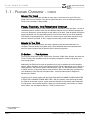
SERIES II
PreAmp Controller
INSTALLATION AND
HOMEOWNERS MANUAL
ELAN
HOME
SYSTEMS
INSTALLATION MANUAL
SERIES II
TABLE
OF
CONTENTS
SECTION 1
Introduction
Congratulations and Thank You . . .
1.1 Feature Overview . . . . . . . . . .
1.2 Z•630 Specs. . . . . . . . . . . . . . .
1.3 Z•630 Front Panel Adjustments
1.4 Z•630 DIP Switch Settings . . . .
.
.
.
.
.
.
.
.
.
.
.
.
.
.
.
.
.
.
.
.
.
.
.
.
.
.
.
.
.
.
.
.
.
.
.
.
.
.
.
.
.
.
.
.
.
.
.
.
.
.
.
.
.
.
.
.
.
.
.
.
.
.
.
.
.
.
.
.
.
.
.
.
.
.
.
.
.
.
.
.
.
.
.
.
.
.3
.6
.8
.9
.9
SECTION 2
Z 630 Users Guide
2.1 Feature Definitions . . . . . . . . . . . . . . . . . . . . . . . . . .10
2.2 Using the Z•030 HandHeld Remote Control . . . . . . . .10
2.3 Factory Default Key Functions . . . . . . . . . . . . . . . . . .11
Z•Series Applications
2.4 Independent Zones . . . . . . . . . . . . .
2.5 One Zone, Two Rooms w/Keypads .
2.6 Creating Zones with Sub-Zones . . . .
2.7 Setting up a “Wide Coverage” Zone .
2.8 The Z•025 Audio Detect Module . . .
2.9 The Z•025 in a Zone with a Sub-Zone
2.10 Commercial Application . . . . . . . . .
.
.
.
.
.
.
.
.
.
.
.
.
.
.
.
.
.
.
.
.
.
.
.
.
.
.
.
.
.
.
.
.
.
.
.
.
.
.
.
.
.
.
.
.
.
.
.
.
.
.
.
.
.
.
.
.
.
.
.
.
.
.
.
.
.
.
.
.
.
.
.
.
.
.
.
.
.
.
.
.
.
.
.
.
.12
.13
.14
.15
.16
.17
.18
SECTION 3
Z•Series System Design
3.1 Designing a System . . . . . . . . . . . . . . . . . . . . . . . . . .19
3.2 System Wire Management . . . . . . . . . . . . . . . . . . . . .20
3.3 Z•Series System and Wire Requirements . . . . . . . . . .21
SECTION 4
Z•630 Connections
4.1 Source Connections . . . . . . . . . . . . . . . . . . . . . . . . .22
4.2 Sharing Sources . . . . . . . . . . . . . . . . . . . . . . . . . . . .22
4.3 IR Emitter Connections . . . . . . . . . . . . . . . . . . . . . . .23
4.4 IR “ALL” Port Connections . . . . . . . . . . . . . . . . . . . . .24
4.5 System Keypad Specifications . . . . . . . . . . . . . . . . . .25
4.6 Z•PAD Connections . . . . . . . . . . . . . . . . . . . . . . . . . .26
4.7 Z•Pads with Z•025s . . . . . . . . . . . . . . . . . . . . . . . . . .27
4.8 Using the PZ6 Precision Panel . . . . . . . . . . . . . . . . . .28
4.9 Multiple Z•630 System Connections . . . . . . . . . . . . . .30
4.10 Connecting a Z•600 to the Z•630 . . . . . . . . . . . . . . . .34
4.11 Connecting a Z•600 to Multiple Z•630s . . . . . . . . . . . .35
SECTION 5
Z•System Troubleshooting
5.1
5.2
5.3
5.4
Page 2
Keypad Operation . .
Infrared . . . . . . . . . .
Audio Source Control
Telecomm . . . . . . . .
.
.
.
.
.
.
.
.
.
.
.
.
.
.
.
.
.
.
.
.
.
.
.
.
.
.
.
.
.
.
.
.
.
.
.
.
.
.
.
.
.
.
.
.
.
.
.
.
.
.
.
.
.
.
.
.
.
.
.
.
.
.
.
.
.
.
.
.
.
.
.
.
.
.
.
.
.
.
.
.
.
.
.
.
.
.
.
.
.
.
.
.
.
.
.
.
.36
.37
.37
.38
© ELAN Home Systems 2002 • All rights reserved. 3/02
ELAN
HOME
SYSTEMS
INSTALLATION MANUAL
SERIES II
CONGRATULATIONS
AND
THANK YOU
You have purchased the highest quality multi-zone controller on the market
today––the Z•630 PreAmp Controller. We at ELAN Home Systems are proud of
this precision component and are pleased you have chosen this ELAN product
as the cornerstone to your audio system. Crafted to be the de facto standard in
its class, the Z•630’s circuit design, small footprint and robust peformance are
the latest in technology and should provide you with years of superior audio
performance. The Z•630 is also available in a rack mount version––the Z•631.
As a manufacturer, ELAN strives to provide you with excellent service after the
sale. If you have any questions or comments concerning the performance,
installation or features of the Z•630 PreAmp Controller, please call the ELAN
Technical Support Department at 1 (859) 269-7760. We are at your service.
Please take a few minutes to read this manual thoroughly. It will help you fully
understand and successfully integrate the capabilities and features of your
Z•630 PreAmp Controller with your existing audio system and speakers.
ELAN Home Systems designs and manufactures the industry’s most complete
line of multi-room audio/video systems and components. For free product information write to us at:
ELAN Home Systems Product Information
2428 Palumbo Drive
Lexington, Kentucky
40509
Look for these other Z•Series Products:
Z•880 Video Controller
Z•600/601 Comm Controller
Z•660/661 Multi-Channel Power Amplifier
Z•300/301 Two-Channel Power Amplifier
Z•FAN Modular Cooling Component
Z•100 and Z•150 Intelligent Keypads
Z•Power Manager
Page 3
© ELAN Home Systems 2002 • All rights reserved. 3/02
ELAN
HOME
SYSTEMS
INSTALLATION MANUAL
SERIES II
Page 4
© ELAN Home Systems 2002 • All rights reserved. 3/02
ELAN
HOME
SYSTEMS
INSTALLATION MANUAL
SERIES II
FEDERAL COMMUNICATIONS COMMISSION (FCC) NOTICE:
This device complies with Part 15 of the FCC Rules. Operation is subject to the following conditions: (1) This device may not
cause harmful interference and (2) this device must accept any interference received, including interference that may cause undesired operation.
Page 5
© ELAN Home Systems 2002 • All rights reserved. 3/02
ELAN
HOME
SYSTEMS
INSTALLATION MANUAL
SERIES II
SECTION 1 - INTRODUCTION
1.1- FEATURE OVERVIEW
The Z•630 Preamp Controller enables you to independently listen to and control up to six different audio sources (i.e. Tuner, CD, Tape Deck and the audio signals from your VCR, DVD and
Satellite Receiver) in three distinct listening areas, or “zones”. As many as three Z•630s may be
used to expand your system to twelve zones.
VIA! Panel, Keypad, or IR Controllable
Whether it’s from a hand-held remote control, an ELAN in-wall Keypad, or VIA! Touch Panel, the
Z•630 Keypad/Infrared interface allows you to easily select a source, adjust the volume, and
enjoy sound in any room of your home. Add multiple Touch Panels, Keypads, or IR Receivers
for maximum flexibility.
EQ, Loudness, and Spacial Enhancement
Just as you have your own listening preferences, each room in your home also has its own
distinct acoustical characteristics. The Z•630 allows you to custom-tailor the bass, treble, loudness contour and spatial sound enhancement for each zone independently. Once set, these
parameters are retained in the Z•630’s flash memory.
Independently Routed IR Outputs
Source-specific IR output ports enable multiple components of the same make and model to be
utilized in your system simultaneously. Want the audio from three DSS receivers available
throughout your home? No problem. The ELAN Z•630 will let you change channels on one without changing the channel on the others.
Bi-D
Directional Communication
The Z•630 communicates with - and receives feedback from VIA! Panels and ZPADS. These
features inform you of which source is currently selected, volume level, mute, Do-Not-Disturb,
EQ settings, and more!
Buffered Source Loop-TThrough Outputs
Every source input on the Z•630 has an accompanying buffered Loop Output. These loop outputs enable any of the sources plugged into the Z•630 to be shared with other devices such as
a Surround Sound Processor or an existing stereo receiver. The loop outputs are also used to
connect your six sources to a additional Z•630s.
Monaural Capable
In how many rooms of your house do you actually sit between two perfectly placed speakers
and listen to music? The Family Room? Sure. The Master Bedroom? Maybe.
* Requires an ELAN
Z•100 keypad
** Impedance
matching volume
controls required
Page 6
Adding single speakers with volume controls in the kitchen, bathrooms, garage, hallways, outdoor patio . . . wherever, is a breeze with the Z•630. The buffered Zone Outputs enable you to
combine the Left and Right audio signals from any selected source and send it to a power
amplifier. Now, from just one amp channel**, you can truly enjoy ‘housewide’ entertainment in
stereo and/or mono simultaneously anywhere in the home.
© ELAN Home Systems 2002 • All rights reserved. 3/02
ELAN
HOME
SYSTEMS
INSTALLATION MANUAL
SERIES II
1.1 - FEATURE OVERVIEW -
CONT.
Music-O
On-H
Hold
The Music-On-Hold output jack provides an easy way to send music from the Z•630 to the
ELAN Z•600 Comm Controller or any phone system that has a music-on-hold input. What is a
Z•600 Comm Controller? Keep reading...
Page, Doorbell, and Telephone Interrupt
The Z•630 Pre-Amp Controller is the perfect system for restaurants, cafes and pubs - as well as
residential systems. Its three zones can can distribute different music for different atmospheres
in the main dining area, private dining area and waiting or bar area. With its special microphone
paging capabilities you can page waiting diners in the bar area while the rest of the establishment listens to uninterrupted music. At home, the music may be muted when the phone rings,
when the doorbell is pressed, or when a page is issued using a touch-tone telephone.
Made in the USA
Designed by ELAN Home Systems’ pro audio engineering staff and manufactured in our
Lexington, Kentucky facility, the highest quality control standards have been implemented to
ensure a superior product that will provide years of listening enjoyment.
Z•Series . . . The System
The Z•Series components (Z•630, Z•600 Comm Controller, Z•880 Video Switcher, and either the
Z•300 or Z•660 power amplifiers) may be seamlessly integrated to create a high-quality and
user-friendly system.
Additionally, the Z•600 will become an essential part of your housewide tele-communications
network, able to distribute whole-house Paging and Door Chime audio through your in-wall or inceiling speakers, and mute the system when the phone rings. The Z•600 also features Phoneto-Phone Intercom, 2-Way Door Station communications, Door Latch and Relay activation from
your telephones, Caller-On-Hold, and Music Mute - as well as other features designed to
enhance your lifestyle.
Complete your Z• Series system with the ELAN Z•660 MULTI-CHANNEL POWER AMPLIFIER
or Z•300 TWO CHANNEL POWER AMPLIFIER. With six channels, each delivering 60 Watts,
the Z•660 is the ultimate in power, sound quality and flexibility for housewide audio distribution.
If a high-power, 2 ohms stable amplifier is what your critical listening, home theater or outdoor
zones require, the 150 Watt-per-channel*** Z•300 is just the ticket.
*** Rated 150WPC into
a 2 Ohm load
Page 7
© ELAN Home Systems 2002 • All rights reserved. 3/02
ELAN
HOME
SYSTEMS
INSTALLATION MANUAL
SERIES II
1.1 - Z 630 FEATURE OVERVIEW -
CONT.
FRONT VIEW
MUSIC ON HOLD
OUTPUT GAIN
PAGE/DOORBELL
SENSE LEVEL
PAGE/DOORBELL INPUT
GAIN
REAR VIEW
Source-Specific
IR Output Ports
VIA! Panel, Keypad, or
IR Sensor input, plus
IR Loop IN/OUT
IR “ALL” Output
(not-Source Specific)
12VDC
Remote Out
Source Inputs with
Buffered Source (Loop) Outputs
Zone-Specific
PreAmp Outputs
IN/OUT for
Music-On-Hold
and Page & Doorbell
1.2 - Z 630 SPECIFICATIONS
FREQUENCY RESPONSE....................20Hz to 20kHz, +/-2.5dB
CHANNEL SEPARATION.....................................70dB Minimum
INPUT IMPEDANCE..................................................24.3k Ohms
VOLUME RANGE...........................-80dB to 0dB, 2dB Step Size
SIGNAL-TO-NOISE...................................>95dB, 1V RMS Input,
A-weighted 1kHz
MUTE ATTENUATION.............................................95dB, Typical
MAXIMUM OUTPUT LEVEL........................................2.3V RMS
TOTAL HARMONIC DISTORTION.... ......... .01%, 300mV Input,
100Hz to 10kHz
MAXIMUM INPUT LEVEL.......................2.0 V RMS @ Clipping,
1% Harmonic Distortion
TYPICAL INPUT LEVEL.............300mV to 2V RMS (Line Level)
REMOTE OUTPUT.................................12 VDC @ 100mA Max.
KEYPAD DC OUTPUT.................................10.6 VDC @ 300mA
DIMENSIONS (HxWxD)
Freestanding.........................................1.75” x 17” x 8”
Rackmount............................................1.75” x 19” x 8”
BASS/TREBLE GAIN LEVEL.................+/-12dB, 2dB Step Size
Page 8
© ELAN Home Systems 2002 • All rights reserved. 3/02
ELAN
HOME
SYSTEMS
INSTALLATION MANUAL
SERIES II
1.3 - Z 630 FRONT PANEL ADJUSTMENTS
MUSIC ON HOLD OUTPUT GAIN
PAGE/DB INPUT GAIN
PAGE/DB SENSE LEVEL
Z630 DIP SWITCHES
Music-On-Hold
Output Gain Adjustment
Page/Doorbell
Sense Level Adjustment
Adjusts the Music-On-Hold output level of Source #1 going to the
Music-On-Hold input on a phone system or the ELAN Z•600
Comm Controller.
Adjusts the sensitivity level needed to automatically trigger a
page from a powered microphone (see Z•630 Commercial
Application, page 18).
Page/Doorbell Input
Gain Adjustment
NOTE: This pot should be turned all the way off when
using the Z•600 Comm Controller.
Adjusts the input level of the Page and Doorbell signal being
received from the ELAN Z•600 Comm Controller
(see Connecting a Z•600 Comm Controller to the Z•630, page
34). Also used to adjust the input level of a powered microphone plugged into the PAGE & DB input (see Z•630
Commercial Application, page 18).
Source Status LED Indicators
SOLID
WINKING
Indicates the source selected in a zone.
Indicates that the zone is in “DO-NOT-DISTURB”.
1.4 - Z 630 DIP SWITCH SETTINGS
Chassis
Chassis
Chassis
Chassis
Page 9
1 (MAIN)
2
3
4
=
=
=
=
Dip
Dip
Dip
Dip
4
4
4
4
-
DOWN
DOWN
UP
UP
Dip 5 - DOWN
Dip 5 - UP
Dip 5 - DOWN
Dip 5 - UP
CHASSIS CONFIG.
CHASSIS CONFIG.
4 and 5. CHASSIS CONFIGURATION DIP SWITCHES. Factory Default - Both DOWN
(Chassis 1 / MAIN).
ZONE 3 VAR / FIX
3. ZONE 3 VAR / FIXED (Factory Default, VAR––Down Position)
Changes the output of Zone 3 from VARIABLE to FIXED
(see Creating Zones with Sub-Zones, page 14)
ZONE 2 VAR / FIX
2. ZONE 2 VAR / FIXED (Factory Default, VAR–Down Position)
Changes the output of Zone 2 from VARIABLE to FIXED (see Creating Zones with
Sub-Zones, page 14)
ZONE 1 VAR / FIX
1. ZONE 1 VAR / FIXED (Factory Default, VAR–Down Position)
Changes the output of Zone 1 from VARIABLE to FIXED (see Creating Zones with
Sub-Zones, page 14)
(Zones 1-3)
(Zones 4-6)
(Zones 7-9)
(Zones 10-12)
© ELAN Home Systems 2002 • All rights reserved. 3/02
ELAN
HOME
SYSTEMS
INSTALLATION MANUAL
SERIES II
SECTION 2 - Z 630 USER’S GUIDE
2.1 FEATURE DEFINITIONS
SPATIAL ENHANCEMENT (ENH)
•
In whole-house system design it is rare indeed that
in-wall speakers can be placed to create an ideal
stereo listening area (i.e. an equilateral triangle
between the listener and the speakers, with the speakers placed at ear level). To compensate for these
imbalances, the SPATIAL ENHANCEMENT feature
widens the stereo soundstage, giving the listener
increased stereo separation between left and right
channels.
•
The ENH feature can be turned on or off independently
in each zone. To reset, press EQ FLAT.
WHOLE-HOUSE MUSIC (WHM)
•
After turning on a zone and selecting a source,
activating the WHOLE-HOUSE MUSIC feature
(WHM ON) will turn on all the other zones in the
house to the source you have selected.
•
When in WHM mode, all the zones are “grouped”.
Change your source selection in one zone, and all the
other zones will follow; change tracks or radio stations
in one zone, and all the other zones will follow.
Volume control in each zone remains independent.
•
Deactivating the WHM feature (WHM OFF) simply
“un-groups” all zones, permitting each zone to once
again act independently of each other. WHM OFF does
not “turn off” any of the zones, it just deactivates the
wholehouse music feature.
2.2
USING THE Z 030 HAND
HELD REMOTE CONTROL
DO-NOT-DISTURB (DND)
•
If your system includes an ELAN Z•600 COMM CONTROLLER, placing a zone in DND will bar PAGE &
DOOR CHIME audio from that zone. It will also disable the TELEMUTE AND WHM feature for that zone.
•
Each zone can be independently placed in DND.
•
If a zone is in DND, the Z•630 Source Select LED for
that zone will wink. If your system includes ELAN
Z•100 keypads, the Power LED on the keypad will wink
if a zone is in DND.
LOUDNESS (LOUD)
•
When listening to music at low levels, the human ear
perceives a loss in both low and high frequencies.
Activating the LOUDNESS contour compensates for
this loss by boosting the Bass and Treble.
•
The LOUDNESS feature can be turned on or off independently in each zone. To reset, press EQ FLAT.
Page 10
© ELAN Home Systems 2002 • All rights reserved. 3/02
ELAN
HOME
SYSTEMS
INSTALLATION MANUAL
SERIES II
Page 11
© ELAN Home Systems 2002 • All rights reserved. 3/02
ELAN
HOME
SYSTEMS
INSTALLATION MANUAL
SERIES II
SECTION 3 - Z SERIES SYSTEM
DESIGNS
AND
APPLICATIONS
3.1 SETTING UP INDEPENDENT ZONES
Separate zones provide you with totally independent
source and system control in each zone. Stereo zones
are appropriate in rooms where the listening area is centrally located between the two speakers (i.e. Family Room,
Master Bedroom.) Mono zones are often used in rooms
where there is no stationary listening area (i.e. Kitchens,
Decks & Patios, Exercise Rooms, etc). Depending on the
size of the room, mono zones can be wired for one, two,
or more speakers. In the scenario below, Zones 1 & 2 are
stereo and Zone 3 is a mono zone with two speakers. All
speakers in each zone are being powered at 60 WPC by
the ELAN Z•660 Multi-Channel Power Amplifier.
Y - Cord
Figure 3.1 - Setting Up Independent Zones
WE RECOMMEND....
Both the Z•630 PreAmp Controller and the Z•660 MultiChannel Power Amplifier are equipped with REMOTE
AUDIO MUTE circuitry. Connecting the Z•630 REMOTE
OUT to the Z•660 REMOTE IN (as shown above) will
eliminate any residual noise (hiss) that may be heard
through the speakers when the system is off, and will also
Page 12
eliminate potential “pops” through the speakers should
power be removed from the system (i.e. power outage).
All that is required for this connection is a “mini-plug” patch
cable.
(NOTE: Should a zone be ON when power is removed, a
“pop” may be heard through the speakers in that zone.)
© ELAN Home Systems 2002 • All rights reserved. 3/02
ELAN
HOME
SYSTEMS
INSTALLATION MANUAL
SERIES II
3.2 ONE ZONE (TWO ROOMS
• Excellent for rooms with common, open areas.
• Provides source select and system control from both
rooms (these functions are not, however, independent)
IN
STEREO
W/KEYPADS)
• Room 1 and Room 2 can be set to different turn on levels (via gain pots on the Z•660), but the VOL
UP/DOWN on either keypad will affect both rooms.
INSTALLATION TIP:
A jumper located on
the back of the Z•025
Sensing/ Relay Module
can enable a special
feature called “Zone
Mute Relay”. When
enabled, both keypads
in this scenario can
independently mute the
speakers in each room
when the MUTE button
on the keypad is
pressed.
NOTE: In this scenario, zone-designating dip switches
on both Z•100’s will be set to Zone 1. (see Z•Pad
installation manual for details)
Figure 3.2 - A Z•630 and Z•660 distributing audio to two separate rooms in stereo within a single zone.
Page 13
© ELAN Home Systems 2002 • All rights reserved. 3/02
ELAN
HOME
SYSTEMS
INSTALLATION MANUAL
SERIES II
3.3 CREATING ZONES
WITH
SUB-ZONES
The dip switches located on the front of the Z•630 enable
you to easily configure zones with sub-zones. When
moved to the UP position, these zone-specific dip switches
disable the VOLUMEUP/VOLUME DOWN buttons on the
keypad and independently “FIX” the output level for each
zone at maximum.
Should the volume on a keypad be turned all the way
down, no level would be available at any of the sub-zone’s
volume controls. By setting the output level to FIXED,
audio will always be present at the volume controls. This
configurations does, however, require that a volume
control be installed in the main zone as well.
SUB-ZONE CONTROL
In this scenario below, Zone 1 is a stand-alone; Zone 2 is
a stereo zone with a stereo sub-zone; and Zone 3 is a
mono zone with three mono sub-zones. Note that the dip
switches for Zones 2 and 3 have been moved to the UP or
“FIXED” position.
When the dip switches are in the DOWN or “VARIABLE”
position, pressing VOLUME UP/VOLUME DOWN on the
keypad would not only raise or lower the volume in the
main zone, but would also affect the volume levels in other
rooms that are a part of that zone (sub-zones).
Make sure to maintain proper impedance loads at the amplifier.
In this diagram, Zone 2 would require impedance matching
stereo volume controls set at 2x, and Zone 3 would require
impedance matching mono volume controls set at 2x (assuming all speakers are 8 ohms).
NOTE: Set Dip Switches 2 and 3
to the UP position to FIX the line
outputs of zones 2 and 3
Figure 3.3
Page 14
Y - Cord
- A three zone system utilizing volume controls in the sub-zones.
© ELAN Home Systems 2002 • All rights reserved. 3/02
ELAN
HOME
SYSTEMS
INSTALLATION MANUAL
SERIES II
3.4
SETTING UP A “WIDE COVERAGE” OR
“UTILITY ” ZONE (ONE ZONE CONSISTING OF MULTIPLE SPEAKERS RUN
IN
MONO
UTILIZING IMPEDANCE
MATCHING VOLUME CONTROLS).
The scenario below is excellent for providing background
music, paging and door chime in secondary areas that do
not require stereo or high-volume listening, i.e. hallway,
laundry room, utility room, garage. Below, only one Z•660
channel is being used for four speakers. Coverage can be
extended to even more rooms by using a second Z•660
channel (with a single patch cord, take the line output of
channel 1 and send it to the line input of channel 2).
NOTE: In the Figure below, Dip Switch #1 (Zone 1
VAR/FIX) on the Z•630 has been set to the UP or “FIXED”
position, which disables the Z•PAD’s VOL UP / DOWN
keys. This configuration provides a full-strength line level
signal to the amplifier and a generous amount of speakerlevel power to the volume controls for use at any time. If
you choose not to listen to music in any given location,
simply turn the Volume Control(s) all the way down.
Z 660 AMP
Z 630 PRE
Set DIP Switch 1 to the UP(or “FIXED”) position.
Set the Impedance Magnification settings as follows:
4x position if utilizing 8 Ohm speakers.
8x position if utilizing 4 Ohm speakers.
Figure 3.4 - Using ELAN VMO Volume Controls to distribute audio (in mono) to four separate rooms within one zone.
Page 15
© ELAN Home Systems 2002 • All rights reserved. 3/02
ELAN
HOME
SYSTEMS
INSTALLATION MANUAL
SERIES II
3.5
THE Z 025 AUDIO DETECT MODULE
The Z•025 is a speaker-level sensing module that plugs
directly onto the back of the Z•100 keypad.
When installed, it automatically detects and routes the
speaker-level signal from either the Z•System or a local
source to the speakers in that zone.
In the scenario below, the speaker-level output from a TV
is automatically routed to the in-wall speakers when the
TV is turned on.
Should the TV be turned off (or if any source select button
on the keypad in this zone is pressed), the Z•025 will automatically switch back to the Z•System.
This scenario works just as well with a local stereo receiver. (See the Z•PAD Homeowner’s/Installation Manual for
detailed wiring information.)
NOTE: See page 27 for a detailed wiring diagram.
PLAN AHEAD
DURING PRE-WIRE
If you intend on
using a Z 025 in a
room, make sure
your amplifier,
speaker, and audio
wiring from your
“local” source are
run to the KEYPAD
location.
The Z•025 also allows for the connection of the Page &
Doorbell Override control signal from a Z•600 Comm
Controller. This permits ELAN Page and Doorbell audio to
pass through into the zone even if you are currently listen-
ing to a local source. The Z•025 will automatically switch
to the Page and/or Doorbell signal when it is sensed, then
switch back to the local source audio when the Page
and/or Doorbell has ended.
Figure 3.5 - Utilizing a Z 025 to override the speaker-level distributed audio feed when a local source (TV) is activated.
Page 16
© ELAN Home Systems 2002 • All rights reserved. 3/02
ELAN
HOME
SYSTEMS
INSTALLATION MANUAL
SERIES II
3.6
THE Z 025
IN A
ZONE
WITH A
SUB-ZONE
PLAN AHEAD
DURING PRE-WIRE
If you intend on
using a Z 025 in a
room, make sure
your amplifier,
speaker, and audio
wiring from your
“local” source are
run to the KEYPAD
location.
Set DIP Switch #1
on the Z 630’s
front panel to the
UP or “FIXED”
position.
The Z•025 also enables the connection of the Page &
Doorbell Override control signal from a Z•600 Comm
Controller. This permits ELAN Page and Doorbell audio to
be heard in the zone wether you are listening to the
distributed audio system or a local source.
The Z•025 will automatically pass the Page and/or
Doorbell signal when it is detected, then switch back to the
original audio source when the Page and/or Doorbell has
ended.
Figure 3.6 - Z•Series connections enabling a MAIN Zone and a Sub-Zone to reproduce audio from Zone 1 of the Z•630,
speaker-level audio from the “local” TV, as well as ELAN Page and Doorbell audio.
Page 17
© ELAN Home Systems 2002 • All rights reserved. 3/02
ELAN
HOME
SYSTEMS
INSTALLATION MANUAL
SERIES II
3.7
UTILIZING THE Z SERIES SYSTEM
COMMERCIAL APPLICATIONS
IN
The Z•630 Page & Doorbell Input can be used with a
powered (line-level) microphone making it a natural for
zoned audio distribution in restaurants, cafes, pubs, offices
and warehouses where paging (in addition to multi-source/
multi-zone music), is desired.
table is ready...”) is activated.
Source equipment, Z•Series components, keypads, and
volume controls can be located in a back room or behind
the bar for easy access to source control, level adjustments, and paging.
In the example below, a restaurant is set up for three
zones. Both dining areas receive uninterrupted music from
independent sources, while the Bar/Waiting Area receives
music from a third independent source which will be
interrupted whenever a page (“Jones party of three, your
NOTE: Always be sure to maintain the minimum load
specification of the amplifier. Multiple Impedance
Magnifying volume controls may be necessary (minimum
load on the volume control is 4 Ohms; minimum load on
the amplifier is 8 Ohms.
IMPORTANT NOTE: Always maintain an 8 Ohm load at
the amplifier. If more than one pair of 8 Ohm speakers is
to be connected in parallel to a given amplifier’s output,
Impedance Magnifying volume controls must be utilized.
INSTALLATION TIP:In Zones where you would not
like the Paging signal to interrupt the music (i.e. a
restaurant’s dining area), be sure to press DND (DoNot-Disturb) on the keypad in that zone .
Figure 3.7 - A typical three zone system installed in a restaurant. Zone 1 has DND disabled, while Zones 2 and 3
have DND enabled so the partons will not hear the Paging. Additionally, Impedance Magnifying volume controls are
used to enable two pairs of 8 Ohm speakers to be connected in parallel and still show the amp an 8 Ohm load.
Page 18
© ELAN Home Systems 2002 • All rights reserved. 3/02
ELAN
HOME
SYSTEMS
INSTALLATION MANUAL
SERIES II
SECTION 4 4.1
DESIGNING
Z SERIES SYSTEM DESIGN GUIDELINES
A
SYSTEM
Home Run ALL Wiring
All wire runs in a Z•System are “home run”; meaning that every keypad, every
speaker or volume control, every telephone line or coax cable path, has its own
dedicated wire run pulled back to the main ELAN components location or ELAN
Wire Management Center (BINT2000, AV/EC BASIC1 or BASIC2).
Plan for the FUTURE
Pulling wire to every keypad, audio, coax and telephone location, even if these
devices will not be installed right away, will save considerable time & money (not
to mention holes in the drywall) in the future. Rule of Thumb: Wherever you
don’t pull wire during the pre-wire phase will be exactly where the customer
would like something installed three months from now!
Map the System
Sit down with the floor plan and decide the number (and the location) of zones
and sub-zones. Include the number, type and location of speakers, the number
and location of keypads, IR receivers and volume controls, as well as the number and location of all telephone and coax wall plates. If using a wire management center like the ELAN BINT2000 to pull all of your wiring to, try to install it in
an easily accessible and centrally located part of the home.
Rooms and Zones
A ‘zone’ is simply a specified listening area. A zone can consist of one room or
many rooms. A single Z•630 system provides you with three zones; as many as
four Z•630 chassis may be linked to create systems containing as many as
twelve zones. Deciding which rooms will have music–– and therefore speakers,
keypads and/or volume controls––should be planned out carefully in advance.
Sub-Z
Zones
Creating a sub-zone off a main zone is an efficient way to distribute audio to
rooms that you’d ‘like’ to have music in, but don’t quite rate (economically
speaking) as zones unto themselves (i.e. a Master Bath attached to the Master
Bedroom, or a Breakfast Nook area near the Kitchen). The Z•630 provides you
with the flexibility to configure sub-zones in a number ways.
The volume in a ‘zone’ is usually controlled by a keypad which increases or
decreases the variable zone outputs that the Z•630 sends to an amplifier. In
sub-zones, however, it may not be economical to add additional keypads, so
you may choose to use volume controls instead. A dip switch located on the
back of the Z•630 can be set to “fix” the variable zone outputs at maximum.
This will disable the volume up/down buttons at the keypad, and give you maximum output to the volume control at all times.
Page 19
© ELAN Home Systems 2002 • All rights reserved. 3/02
ELAN
HOME
SYSTEMS
INSTALLATION MANUAL
SERIES II
4.1
DESIGNING
A
SYSTEM -
CONT.
Monaural (Mono)
When it comes to house-wide audio distribution, there may actually be more
applications for mono listening areas than stereo. Kitchens, patios, decks, hallways, bathrooms, laundry rooms––any room where you are not going to be sitting comfortably between a pair of speakers - may all benefit from being wired in
mono.
Single or multiple speakers wired in a mono configuration simply means that
you are getting both the left and right channel information through one speaker––it does not mean that you are getting poorer sound. It is also a great way
to cut costs without compromising quality and providing full sound in locations
where the use of two speakers isn’t justified or practical.
Zone and Sub-Z
Zone Scenarios
The buffered zone outputs on the Z•630 make it easy to configure stereo or
mono zones and sub-zones. If you are also using ELAN’s Z•660 Multi-Channel
Power Amplifier, its buffered inputs and loop outputs may be combined with
those of the Z•630, give you virtually limitless zone configuration options.
On pages 12 through 18 in this manual, we have provided seven unique zone
configuration scenarios which show different ways to create zones and subzones. These Sub-Zones may be configured for stereo or mono operation, and
may utilize keypads and/or volume controls.
4.2
SYSTEM WIRE MANAGEMENT
Wire management is extremely important in all multi-room systems, but even
more so when the wiring for Audio, Video, and Telephone are all being run back
to one system that does it all––the ELAN Z•Series.
Use of the ELAN BINT2000 Wire Management Center and TBK2000 Telephone
Punchdown Block is a convenient, cost-effective way to house and terminate the
bulk of the structured wiring in a new home.
Once all the wires are terminated at this location, only a few wire runs––in a
nice, neat snake––need to be pulled back to the “head-end” or main equipment
location.
Also note that the BINT2000, with its mounting pan and built-in power strip, is
the ideal location for housing a video modulator and any RF distribution amplifiers or splitters that may be incorporated into your distributed entertainment
system. The BINT2000 mounts easily in any standard stud bay.
Page 20
© ELAN Home Systems 2002 • All rights reserved. 3/02
ELAN
HOME
SYSTEMS
INSTALLATION MANUAL
SERIES II
4.3
Z SERIES SYSTEM
AND
WIRING REQUIREMENTS
(VSE/VSO/VMO)
(x4)
DSC2000/DS1500/1550
Figure 4.3 - ELAN Z Series system wiring.
Page 21
© ELAN Home Systems 2002 • All rights reserved. 3/02
ELAN
HOME
SYSTEMS
INSTALLATION MANUAL
SERIES II
SECTION 5 -
5.1
Z 630 CONNECTIONS
SOURCE CONNECTIONS
In a multiple Z•630 systems, the buffered source loop outputs are used to
send the source signal from the MAIN Z•630 to the AUX Z•630s.
#2
5.2
SHARING SOURCES
The Z•630’s buffered source loop outputs enable you to
share any source connected to the Z•630 with other
devices such as a Surround Sound Processor or A/V
Receiver (i.e. in the diagram below, the CD player is
accessible in all zones, as well as in the main media room
or home theater).
Page 22
NOTE:
1. ALL system connections
should be made with the
components unplugged.
2. Never remove power from
the system if any zone is on.
3. Simply duplicate the connections shown if utilizing additional Z•630s.
4. See page 9 for multiple
Z•630 DIP Switch settings.
NOTE: 1. ALL system connections should be made with
the components unplugged.
2. Never remove power from the system if any of
the zones are on.
3. Simply duplicate the connections shown if
utilizing additional Z•630s.
4. See page 9 for multiple Z•630 DIP Switch
settings.
© ELAN Home Systems 2002 • All rights reserved. 3/02
ELAN
HOME
SYSTEMS
INSTALLATION MANUAL
SERIES II
5.3
IR EMITTER CONNECTIONS
The Z•630’s source-specific IR output ports enable
independent IR control of all six sources.
NOTE: These six IR outputs are routed, enabling identical
components to be utilized independently.
Each IR output port corresponds to a specific source input
number (i.e. source input 1 = IR port 1, etc.). An IR emitter (ELAN IR2040) should be plugged in to the appropriate
IR port and paced over the IR receiver window on the
corresponding source. Different sources may have different IR signal strengths. Sources whose remote’s feature
high-output may require you to slightly offset the Emitter
from the component’s window. When using sources of the
same make or model number, “masking” the IR emitter
may be necessary to prevent the output of one IR emitter
from reaching the other source components.
Single Z 630 IR Emitter Connections
Multiple Z 630 IR Emitter Connections
Figure 5.3 - Using the Z•630’s IR LOOP IN/OUT to “daisy-chain” multiple chassis together and to enable source
components to be shared by all zones. NOTE: See page 9 for multiple Z•630 DIP Switch settings.
Page 23
© ELAN Home Systems 2002 • All rights reserved. 3/02
ELAN
HOME
SYSTEMS
INSTALLATION MANUAL
SERIES II
5.4
IR “ALL” PORT CONNECTIONS
Controlling Additional Components
Although the Z•630 can directly select and control up to six
sources, a seventh source (i.e. an A/V Receiver) may be
controlled via the Z•630’s ALL port IR Pass-Thru feature.
Additionally, if multiple Z•630s are used, the “IR ALL” ports
on the AUX Z•630s may be utilized to control additional
source components from any zone on any chassis.
Page 24
In the scenario below, the A/V Receiver may select any of
the sources it is “sharing” with the Z•630 using the
receiver’s original hand-held remote––or a learning remote
which has been programmed to control the receiver, the
source components, and the ELAN Z•630.
© ELAN Home Systems 2002 • All rights reserved. 3/02
ELAN
HOME
SYSTEMS
INSTALLATION MANUAL
SERIES II
5.5
SYSTEM KEYPAD SPECIFICATIONS
The specifications below apply to the following ZPAD combinations (when utilizing the Z•630’s internal power supply to
power the Keypads):
a.
b.
Z•100 Single-gang Keypad only
Z•100 Single-gang Keypad and Z•150 Direct Access Keypad with IR Receiver
NOTE: An outboard power supply may be utilized to power additional ZPADS if desired. Call ELAN Tech
Support for power supply specifications.
Maximum
Maximum
Maximum
Maximum
number
number
number
number
of
of
of
of
Keypads per zone
Keypads per Z•630
Z•630s per system
Keypads per system
2
6
4
24
NOTE: If utilizing Z•025 Audio Detect Modules (see page 27) an external 12VDC plug-in power supply (ELAN
Z•027) must be used. Each ELAN 12VDC plug-in power supply will power up to three Z•025s. A maximum of
six Z•025s per Z•630 (24 per quad Z•630 system) may be used.
Pin#
1
2
3
4
5
6
7
8
Z•630 IR Input Jack
Zone 1, 4, 7,10
Zone 2, 5, 8,11
Zone 3, 6, 9,12
RS485 +
RS485 +12VDC
Ground
PAGE Control
Color Code
Blue
White/Blue
Orange
White/Orange
Green
White/Green
Brown
White Brown
Zone 1/4/7/10 Z•100 Zone 2/5/8/11 Z•100 Zone 3/6/9/12 Z•100
White/Blue
White/Blue
White/Blue
White/Orange
White/Orange
White/Orange
Green
Green
Green
White/Green
White/Green
White/Green
Brown
Brown
Brown
Z 630 / Z PAD Connection Reference Table
Z 630 / IR Sensor Connection Reference Table
Z•630 Function
Zone 1, 4, 7,10 IR
Zone 2, 5, 8,11 IR
Zone 3, 6, 9,12 IR
RS485 +
RS485 +12VDC
Ground
PG & DB Control
Page 25
Z•630 Wire Color Key Zone 1, 4, 7,10 RC3000 Zone 2, 5, 8,11 IRC3000 Zone 3, 6, 9,12 IRC3000
Blue
Send (Data)
White/Blue
Send (Data)
Orange
Send (Data)
White/Orange
Green
White/Green
+12VDC
+12VDC
+12VDC
Brown
Ground
Ground
Ground
White Brown
© ELAN Home Systems 2002 • All rights reserved. 3/02
ELAN
HOME
SYSTEMS
INSTALLATION MANUAL
SERIES II
5.6 Z PAD CONNECTIONS
Both the Z•630 and the ELAN Z•PADs utilize the RJ-45
quick connect plugs. To save time and eliminate potential
termination problems, we strongly recommend the use of
ELAN’s pre-terminated RJ45-to-Pigtail cable, the C45P
RJ-45 Interface Cable. Independent runs of 22/24 gauge,
4 twisted-pair telephone wire (or standard CAT5) are used
to connect to the C45P plugged into each Z•PAD and the
C45P at the Z•630.
INSTALLATION TIP
ELAN recommends the use of the
PZ6 Precision Panel for quick and
easy Z System wire terminations.
See the PZ6 Manual and page 28
of this document for details
Page 26
© ELAN Home Systems 2002 • All rights reserved. 3/02
ELAN
HOME
SYSTEMS
INSTALLATION MANUAL
SERIES II
5.7 Z PADS
WITH
Z 025S
INSTALLATION TIP
ELAN recommends the use of
the PZ6 Precision Panel for
quick and easy Z System wire
terminations. See the PZ6
Manual and page 28 of this document for details
ELAN Z 027
12VDC
Regulated
Power Supply
Page 27
© ELAN Home Systems 2002 • All rights reserved. 3/02
ELAN
HOME
SYSTEMS
INSTALLATION MANUAL
SERIES II
5.8 USING
THE
PZ6 Z SERIES PRECISION PANEL
ELAN’s PZ6 Precision Wall Plate enables ‘plug-and-play’
installation of Z•Series Multi-Source/Multi-Zone systems.
The PZ6 was designed with the custom installer in mind,
and meets the design goal of cutting hours off of every
Z•Series installation while assuring that all system wire
runs and Z• Series components are connected properly
first time, every time.
FEATURES
Front Panel RJ45 Jacks
Accommodate the connection of every ELAN
Z•Series component, including a dual Z•630 sixzone system (two PZ6s may be linked to accomodate a quad Z•630 system). ELAN's new line of
Essential Cables include 1 and 2 meter RJ45-toRJ45 interconnects that make all component
connections plug-and-play.
No “Butt-Splicing”
The PZ6 completely eliminates the need to interconnect ELAN Z•Series components. Previously,
numerous 'butt-splices' were required to connect
Page 28
the Z•630 PreAmp Controller, the Z•600 Comm
Controller and the Z•880 Video Controller so that
they could 'talk' to each other. Now, the PZ6’s
circuit board does all of that for you.
Standard 110 Punchdown Block
The rear panel features a standard 110 punchdown connector for every Z•Series wire run,
including Z•PADs, Z•025 modules, Door Speaker
Assemblies, Relays, Volume Control Overrides,
Telephone and even a punchdown connector that
will interface with VIA! LCD Touch Panel Precision
Wall Plates.
Clearly Labeled Connections
The PZ6’s front panel is clearly silkscreened to
make the connection of Z•Series components
quick and easy. The rear panel PC board is
labeled with the name and function of each punchdown connection. To make things even easier, a
rear panel color-code overlay is included with each
PZ6. Just match up every Z•PAD and Door
Speaker Assembly wire to the corresponding
connector and punch it down!
© ELAN Home Systems 2002 • All rights reserved. 3/02
ELAN
HOME
SYSTEMS
INSTALLATION MANUAL
SERIES II
5.8 THE PZ6 Z SERIES PRECISION PANEL- CONT.
Gold-plated Binding Posts
The PZ6 also features twelve gold-plated 5-way
binding post for professional speaker wire terminations. For clean, ‘no-short’ connections, ELAN
recommends the use of its "BLACKJACK" goldplated Banana plugs, which are accepted on both
sides of the PZ6’s binding posts.
+12VDC Inputs
Two +12VDC Inputs are provided on the front of
the PZ6 to enable Z•025 & VCO relay control.
Simply plug in ELAN's Z•027 power supply and
the PZ6 automatically routes the power to the
appropriate punchdown terminals.
RCA-to-F Barrel Connectors for Video
Eight RCA-to-F barrel connectors enable easy
connection of all your coax wire runs to the Z•880
Video Controller or other video distribution
components.
Page 29
© ELAN Home Systems 2002 • All rights reserved. 3/02
ELAN
HOME
SYSTEMS
INSTALLATION MANUAL
SERIES II
5.9 MULTIPLE Z 630 SYSTEM CONNECTIONS
1. Decide which Z•630 will be your MAIN (Zones 1-3) and
which chassis will be AUXILIARY (Zones 4-6, 7-9, 1012).
5. IR emitters for each source should be connected to the
corresponding outputs on the “MAIN” Z•630’s IR output
ports. (See IR EMITTER CONNECTIONS on page 23).
2. Peel back the Lexan strip on the front panel of the
AUXILIARY Z•630(s), and assign chassis ID numbers
to the AUX units using DIP Switches #4 and #5. (See
page 9 for the appropriate Chassis ID settings for each
Z•630. NOTE: The “MAIN” Z•630’s #4 and #5 DIP
Switches should remain in the DOWN position.
6. Use ELAN C4545 RJ45-to-RJ45 interconnects to link
each each of the Z•630’s IR LOOP IN/OUT ports
together.
3. If not utilizing a PZ6 Precision Panel, connect RS485+/connections between all the Z•630s in the system. (See
details on page 26).
4. Source components should be connected to the MAIN
Z•630 first, then looped out from the MAIN Z•630 to the
AUX Z•630s (see SOURCE CONNECTIONS on page
22).
Page 30
7. Keypads, VIA! Panels, and/or IR Receivers are connected as follows:
Zones 1-3 to CHASSIS 1(MAIN).
Zones 4-6 to CHASSIS 2.
Zones 7-9 to CHASSIS 3
Zones 10-12 to CHASSIS 4
(See pages 25 and 26 for more detailed information).
8. Connect the Zone Outputs of each Z•630 to the amp
channels dedicated to each zone (not shown).
© ELAN Home Systems 2002 • All rights reserved. 3/02
ELAN
HOME
SYSTEMS
INSTALLATION MANUAL
SERIES II
5.9 MULTIPLE Z 630 SYSTEM CONNECTIONS - CONT.
RS-4
485 / P&DB CONNECTIONS (ONLY NECESSARY WHEN NOT USING A PZ6 ).
NOTE: Only 4 wires (RS-485 +/-, PAGE & DOORBELL CONTROL, and GROUND) need to
be tied together between the Z 630’s WHEN NOT USING A PZ6. The P&DB Control wires
are to be paralleled together and connected to pin 1 of the Z 600 Comm Controller.
Page 31
© ELAN Home Systems 2002 • All rights reserved. 3/02
ELAN
HOME
SYSTEMS
INSTALLATION MANUAL
SERIES II
5.9 MULTIPLE Z 630 SYSTEM CONNECTIONS - CONT.
LINKING TWO PZ6 PRECISION PANELS TOGETHER TO ACCOMMODATE THREE
OR FOUR Z 630 CHASSIS.
PZ6 #1
The new version of the PZ6 enables the 485+/-,
PAGE & DOORBELL CONTROL, as well as the
PZ6’s GROUNDs to be linked. NOTE: The PZ6s
must have production dates later than 2/19/02.
This configuration enables the connection of as many
as four Z 630 chassis as well as the neat and clean
termination of all associated Z Series system wiring.
GROUND
If three or four Z 630 chassis will be linked using
two PZ6s, the diagram to the right details the connections of the RS485+, RS485 -, Z 600Page/Doorbell,
and Ground between the two PZ6s.
P&DB
GROUND
P&DB
PZ6 #2
Page 32
© ELAN Home Systems 2002 • All rights reserved. 3/02
ELAN
HOME
SYSTEMS
INSTALLATION MANUAL
SERIES II
5.9 MULTIPLE Z 630 SYSTEM CONNECTIONS - CONT.
LINKING TWO PZ6 PRECISION PANELS TOGETHER TO ACCOMMODATE A THREE
OR FOUR CHASSIS Z SYSTEM.
Z 600
Z 630 #1 (Zones 1-3)
Z 630 #2 (Zones 4-6)
CAT 5 (See page 32)
When linking two PZ6s together to support a
multiple chassis Z 630 system with a single
Z 600 Comm Controller, PZ6 #2’s Z 600
RJ-45 jack inputs are not used.
Z 630 #3 (Zones 7-9)
Z 630 #4 (Zones 10-12)
Page 33
© ELAN Home Systems 2002 • All rights reserved. 3/02
ELAN
HOME
SYSTEMS
INSTALLATION MANUAL
SERIES II
5.10 CONNECTING A Z 600 COMM CONTROLLER
TO THE Z 630 (NO PZ6)
There are three connections which must be made
to link the Z 600 to the Z 630:
1. Page and Doorbell Override Control
This connection must be made so the Z 630 will
mute whatever audio signal is currently playing in
each zone and permit the Page and Doorbell audio
signal to be passed through.
2. Page and Doorbell Audio*
The Page and Doorbell audio output of the Z 600
must be connected to the Page and Doorbell audio
input on the Z 630. ( * a single stereo interconnect
cable may be used to connect both the Page and
Doorbell as well as Music-On-Hold signals).
3. Music-On-Hold (MOH)*
The Music-On-Hold output from the Z 630 sends a
summed mono signal from Source 1 to the MOH input
on the Z 600.
For example, if you have a tuner connected to the
Z 630’s Source 1 input (and the Tuner is left ON all
the time), whenever a caller is placed on hold they will
automatically hear the audio from the Tuner in the tele
phone headset until the call is taken off Hold again.
( * a single stereo interconnect cable may be used to
connect both the Page and Doorbell as well as MusicOn-Hold signals).
NOTE: The above mentioned
connections may be quickly
and easily terminated using
the PZ6 Precision Panel .
Page 34
© ELAN Home Systems 2002 • All rights reserved. 3/02
ELAN
HOME
SYSTEMS
INSTALLATION MANUAL
SERIES II
5.11 CONNECTING THE Z 600 COMM
CONTROLLER TO MULTIPLE Z 630S (NO PZ6)
1. In a multiple Z 630 system, the Page and Doorbell
Output of the Z 600 must be “Y’d” to the Page and
Doorbell Input of all the Z 630s.
3. The Page and Doorbell Control wire from the Z 600
connects to all of the Z 630s.
2. ONLY the MAIN Z 630’s Music-On-Hold Output should
be sent to the Z 600’s MOH Input.
NOTE: The above
mentioned connections
may be quickly and
easily terminated using
the PZ6 Precision
Panel .
Page 35
© ELAN Home Systems 2002 • All rights reserved. 3/02
ELAN
HOME
SYSTEMS
INSTALLATION MANUAL
SERIES II
SECTION 6 -
Z SYSTEM TROUBLESHOOTING GUIDE
ELAN “O N-S
S ITE ” T ECHNICAL SUPPORT 1(800) 622-E
ELAN (3256)
6.1 KEYPAD OPERATION
NOTE: When troubleshooting Keypads, always make sure the
keypad’s DIP switches are set properly, and the switches are
firmly seated in either the UP or DOWN position.
SYMPTOM
POSSIBLE CAUSE
WHAT TO DO
•
1. White/Green (+12V) and/or Brown wire
(GND) not connected or shorted
1. Confirm connections
(see pages 25 & 26)
2. Maximum number of keypads per zone or
per Z•630 has been
exceeded
2. See pg. 25 for system maximums
Keypad controls Z630 & sources,
System LED is lit, but source
LED will not track sources, no
Mute LED
1. RS485+/- connections at keypad improperly wired
1. Confirm connection
(see pages 25 & 26)
2. DIP switch setting may be incorrect
(Keypad / Z•630)
2. Confirm DIP configuration
(see pages 9)
•
Keypad LEDs are lit, but will not
control Z•630 or sources
1. White/Blue wire (IR send) connected
incorrectly (or not at all)
1. Confirm connection
(see pages 25 & 26)
•
Z•100 power LED is lit, but no
other LEDs. Keypad controls the
wrong zone.
1. The White/Blue wire from the Z•100 is
connected to the wrong Z•630 zone IR
wire
1. Confirm wiring
(see pages 25 & 26)
2. The Z•100 dip switch is set to the wrong
zone
2. Confirm dip switch setting
(see Z•PAD installation manual)
Press any key on the Z•100 or
Z•150, power LED flashes red,
does not stay on or turn green,
keypad controls the right zone,
but no LED feedback
1. The Z•100 dip switch is in ELAN Series
HD mode
1. Set dip switch to proper zone
setting (see Z•PAD Installation
Manual)
2. RS485+/- connections at keypad improperly wired
2. Confirm wiring
(see pages 25 & 26)
No keypad LEDs, keypad controls proper zone
1. Z•630 MAIN/AUX DIP switch set to wrong
position
1. See pg. 9 for DIP switch settings
2. Z•100 DIP switch settings incorrect
2. See pg. 9 for DIP switch settings
•
•
•
Keypad totally inoperable
(no functions, no LEDs)
•
Unable to control volume from
keypad, preamp output is full
blast
1. Zone output on Z•630/MCU is set to
“FIXED”
1. See pg. 9
•
System LED on the Z•100 in a
zone in a constant slow wink
1. Zone is in Do-Not-Disturb
1. Press *, MUTE on the Z•100 or DND
on the Z•030 hand-held remote
(see pages 10)
Page 36
© ELAN Home Systems 2002 • All rights reserved. 3/02
ELAN
HOME
SYSTEMS
INSTALLATION MANUAL
SERIES II
6.2 INFRARED
SYMPTOM
POSSIBLE CAUSE
WHAT TO DO
• No IR pass-thru, IR indicator LED
1. The IR tube connector is not plugged
in correctly (tab up) to the Z•150
1. See Z•PAD installation manual
2. The White/Blue wire (IR Send) from the
Z•100 to the Z•630 is not connected
2. Confirm connection
(see pages 25 & 26)
1. IR window is being flooded.
1. Cut out a small circle of paper and
place it behind the IR window of the
keypad or other IR receiver. If the
flooding is severe, double up on the
thickness of the paper.
always on orange
• Power LED on the Z•100 and IR
activity LED on Z•630 are flickering
orange. Keypad/IR receiver in that
zone may be inoperable or have
intermittent operation.
If the LEDs flash on their own, the IR
tube in the Z•150, or another IR receiver in that zone, is probably being flooded by ambient light. To confirm this,
place your hand over the IR receiver in
that zone. If the flashing stops, you
have confirmed that it is being flooded.
If flooding persists, the interference
may be inductive, i.e. caused by the
keypad’s proximity to a light dimmer.
In this instance, the keypad or dimmer
may have to be moved, or the dimmer
may be swapped out for a higher
quality unit with better shielding.
6.3 AUDIO SOURCE CONTROL
SYMPTOM
POSSIBLE CAUSE
WHAT TO DO
• No audio from one or more source,
1. Sources may be plugged into the loop
out jacks instead of the source input
jacks
1. Plug sources into source input
jacks (see pg. 22)
Single Z•630 system
1. IR emitter plugged into wrong IR output
port
1. Make sure the source’s IR port
position matches that of the
source’s audio input position
Multiple Z•630 system
2. If not above, see page 23 for more info
2. Confirm above. See page 23 for
more info
1. RS485+/- connection between the
two Z•630s not made or mis-wired.
1. See pages 31& 32
all other functions on keypads and
Z•630 seem operable
• Unable to control source(s) from
keypad
• In a multiple Z•630 system––no
Wholehouse Music feature, System
ON/OFF turns on/off one Z•630 but
no the other.
Page 37
© ELAN Home Systems 2002 • All rights reserved. 3/02
ELAN
HOME
SYSTEMS
INSTALLATION MANUAL
SERIES II
6.4 TELECOMM
SYMPTOM
POSSIBLE CAUSE
WHAT TO DO
• No Music-On-Hold
1. Source #1 is not on
1. Turn on Source #1
2. The MOH output level on the Z•630 or
the MOH input level on the Z•600 is
turned down
2. Adjust levels (see pg. 26 in the
Z•600 manual and pg. 8 in this
manual)
1. Zone is in Do-Not-Disturb
1. Press *, MUTE on the Z•100 or DND
on the Z•030 hand-held remote
(see pg. 10)
2. Page/DB output from Z•600 not
plugged into Page/DB input on Z•630
-and3. The Page & Doorbell control wire
between the Z•630 and the Z•600 is
not connected
2. Connect Page/DB output from Z•600
to Page/DB input on Z•630 (see pg.
34)
1. Z•630 Page/DB input level adjustment or Z•600 Page/DB output level
turned all the way down
1. Increase Page/DB gain adjustment on
Z630 (see pg. 8).
2. Page/DB output from Z•600 not
plugged into Page/DB input on Z•630
2.Connect Page/DB output from Z•600
to Z•630 Page/DB input (see pg 34)
• No Page or Door Chime audio (music
does not mute when page or doorbell
is activated)
• No Page or Door Chime audio (music
mutes when page or doorbell is activated)
3. Connect Page & Doorbell control wire
(see pg. 34)
• There is a 3 second delay before the
music comes back on after a page, ---ORSystem will not come out of Page
1. The sense level adjustment on the
front of the Z•630 is turned up
1. Turn the sense level adjustment
all the way down (see pg. 8)
• (Mic Application) Page cuts out while
speaking
1. Sense level adjustment set too low
1. Turn up Sense level adjustment
• (Mic Application) Page triggering on
its own
1. Sense level adjustment set too high
1. Turn down Sense level adjustment
• Page/Doorbell too loud or too low
1. Page/DB output level adjustment on
the Z•600 and/or Page/DB input level
adjustment on the Z•630 is not set
properly
1. Adjust Page/DB output level on 600
and/or Page/DB input level on Z•630
(see pg. 26 in the Z•600 manual or
pg. 8 in this manual)
• No Page or Door Chime audio when
all zones are off and a Page or Door
Chime is initiated
1. The remote out of the Z•630 is connected to an amplifier with a power up
delay
1. Disconnect the Remote Out to the
amplifier and leave amp on, or replace
amplifier with one that does not have
a power up delay (such as the ELAN
Z•660)
Page 38
© ELAN Home Systems 2002 • All rights reserved. 3/02
ELAN
HOME
SYSTEMS
INSTALLATION MANUAL
SERIES II
630 PREAMP CONTROLLER
Limited Warranty
ELAN HOME SYSTEMS, L.L.C. (“ELAN”) warrants the Z•630 PreAmp Controller manufactured
by it to be free from defects in materials and workmanship for two (2) years from the date of purchase. If within the applicable warranty period above purchaser discovers such item was not as
warranted above and promptly notifies ELAN in writing, ELAN shall repair or replace the items at
the company’s option. This warranty shall not apply (a) to equipment not manufactured by ELAN,
(b) to equipment found to have been installed by other than an authorized ELAN installer, (c) to
installed equipment which is not installed to ELAN’s specifications, (d) to equipment found to have
been repaired or altered by others than ELAN, (e) to equipment found to have been subjected to
negligence, accident, or damage by circumstances beyond ELAN’s control, including, but not limited to, lightning, flood, electrical surge, tornado, earthquake, or any other catastrophic events
beyond ELAN’s control, or to improper operation, maintenance or storage, or to other than normal
use of service. With respect to equipment sold by, but not manufactured by ELAN, the warranty
obligations of ELAN shall in all respects conform and be limited to the warranty actually extended
to ELAN by its supplier. The foregoing warranties do not cover reimbursement for labor, transportation, removal, installation, or other expenses which may be incurred in connection with repair
or replacement.
Except as may be expressly provided and authorized in writing by ELAN, ELAN shall not be subject to any other obligations or liabilities whatsoever with respect to equipment manufactured by
ELAN or services rendered by ELAN.
THE FOREGOING WARRANTIES ARE EXCLUSIVE AND IN LIEU OF ALL OTHER
EXPRESSED AND IMPLIED WARRANTIES EXCEPT WARRANTIES OF TITLE, INCLUDING
BUT NOT LIMITED TO IMPLIED WARRANTIES OF MERCHANTABILITY AND FITNESS FOR
A PARTICULAR PURPOSE.
Page 39
© ELAN Home Systems 2002 • All rights reserved. 3/02