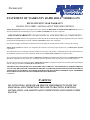
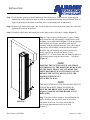
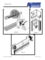
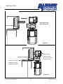
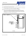
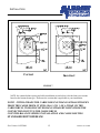
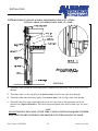
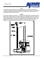
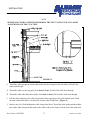
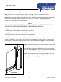
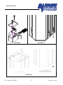
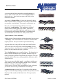
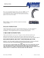
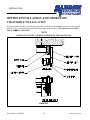
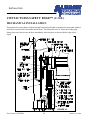
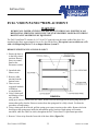
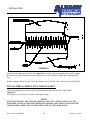
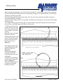
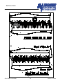
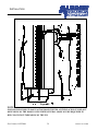
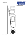
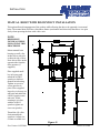
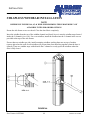
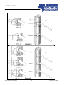
1
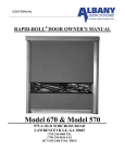
USER MANUAL
RAPID-ROLL® DOOR OWNER’S MANUAL
Model 670 & Model 570
975-A OLD NORCROSS ROAD
LAWRENCEVILLE, GA 30045
(770) 338-5000 TEL
(770) 338-5034 FAX
(877) 925-2468 TOLL FREE
ARCHITECTURAL
Architectural Drawing of the 570 & 670 Rapid Roll Door
Models.
Part Number 6410T0006
2
Release 9/7/2004
ARCHITECTURAL
Table of Contents
STATEMENT OF WARRANTY RAPID ROLL® MODELS 670 .................................................................4
SAFETY PRACTICES ....................................................................................................................................5
PACKING LIST ...............................................................................................................................................6
RAPID ROLL® MODEL 570/670 INSTALLATION ......................................................................................7
FRAME AND GENERAL INSTALLATION .............................................................................................7
COUNTER-BALANCE SPRING INSTALLATION AND CABLE ROUTING..........................................12
STANDARD BOTTOM BEAM................................................................................................................12
BOTTOM BEAM EQUIPPED WITH SELF-REPAIRING DEVICE™ OPTION. ..................................16
BOTTOM BEAM EQUIPPED WITH RAPID RESET™ OPTION. (Model 670 Only) ..........................19
SPRING TENSIONING AND DOOR BALANCE .......................................................................................19
MAINTENANCE AND INSPECTION.........................................................................................................22
DAILY INSPECTION................................................................................................................................22
QUARTERLY INSPECTION....................................................................................................................22
RAPID ROLL DOOR 570/670 MAINTENANCE CHECKLIST ............................................................23
INSPECTIONS...........................................................................................................................................24
PULLEY INSPECTION.............................................................................................................................26
CABLE DRUM INSPECTION..................................................................................................................26
SELF-REPAIRING DEVICE™ BOTTOM BEAM TYPE .......................................................................26
BRAKE ADJUSTMENT ...........................................................................................................................27
OPTION INSTALLATION AND OPERATION ..........................................................................................28
CHAIN DRIVE INSTALLATION.............................................................................................................28
CONTACTLESS SAFETY EDGE™ (C.S.E.) .............................................................................................30
MECHANICAL INSTALLATION............................................................................................................30
ELECTRICAL INSTALLATION ..................................................................................................................31
ADJUSTMENTS .......................................................................................................................................32
FULL ROLL COVER & MOTOR COVER INSTALLATION ....................................................................34
FULL VISION PANEL™REPLACEMENT .................................................................................................35
MANUAL DISENGAGEMENT ..................................................................................................................40
MANUAL DISENGAGEMENT ...................................................................................................................41
MANUAL HOIST INSTALLATION ............................................................................................................43
MANUAL HOIST WITH DISCONNECT INSTALLATION .....................................................................44
WINDBAR INSTALLATION .......................................................................................................................46
STRAPPED WINDBAR INSTALLATION ..............................................................................................46
STRAPLESS WINDBAR INSTALLATION ................................................................................................49
AIR CIRCULATION SYSTEM ....................................................................................................................51
MECHANICAL INSTALLATION............................................................................................................51
ELECTRICAL INSTALLATION ..............................................................................................................52
AIR FLOW ADJUSTMENTS ...................................................................................................................53
RAPID ROLL® MODEL 570/670 INSTALLATION CHECKLIST.............................................................55
Part Number 6410T0006
3
Release 9/7/2004
PACKING LIST
STATEMENT OF WARRANTY RAPID ROLL® MODELS 670
EXCLUSIVE FIVE YEAR WARRANTY
ON ROLLTEX FABRIC AND BALANCE/TENSIONING SPRINGS
Albany International warrants to the original owner of the door that the ROLLTEX and TENSIONING SPRINGS will be free of
defects in materials and workmanship for a period of FIVE (5) YEARS from the date of shipment.
ONE YEAR WARRANTY ON MECHANICAL AND ELECTRICAL COMPONENTS
Albany Door Systems warrants to the original owner of the door that the mechanical and electrical components will be free of defects
in material and workmanship for a period of twelve (12) months from the date of shipment.
Only defects brought to the attention of Albany Door Systems during the warranty period will be covered by this warranty.
Albany Door Systems will replace any component parts found to be defective upon inspection by an Albany Door Systems
representative.
This warranty does not cover damage caused by collision or other abuse of the product. Adjustments made to the Control Panel or to
the mechanical operation of the door without the authorization of Albany Door Systems will void this warranty.
The replacement provisions shall be the limit of Albany Door Systems responsibility under this warranty and Albany Door Systems
shall not be responsible for any other losses or damages due to the operation of any door or parts covered by this warranty.
No other oral or written representations made by Albany Door Systems or its agents are a part of this warranty unless specifically set
forth in writing by an authorized Albany Door Systems official.
THE ABOVE SET FORTH WARRANTY IS SELLER'S SOLE WARRANTY. SELLER MAKES NO OTHER WARRANTY
OF ANY KIND WHATSOEVER, EXPRESSED OR IMPLIED. ALL IMPLIED WARRANTIES OF MERCHANTABILITY
AND FITNESS FOR A PARTICULAR PURPOSE WHICH EXCEED THE AFORESTATED OBLIGATION ARE HEREBY
DISCLAIMED BY SELLER AND EXCLUDED FROM THIS AGREEMENT.
USW1RR.95
WARNING
DO NOT INSTALL, OPERATE, OR SERVICE THIS PRODUCT UNLESS YOU
HAVE READ AND UNDERSTAND THE SAFETY PRACTICES, WARNINGS,
INSTALLATION, AND MAINTENANCE INSTRUCTIONS CONTAINED IN THIS
MANUAL.
INSTALLATION
SAFETY PRACTICES
WARNING
THOROUGHLY READ THESE SAFETY PRACTICES PRIOR TO INSTALLING, OPERATING, OR
SERVICING A HIGH-SPEED, RAPID ROLL® DOOR. FAILURE TO FOLLOW THESE SAFETY
PRACTICES MAY RESULT IN PROPERTY DAMAGE, PERSONNEL BODILY INJURY, OR
DEATH.
1.
Do not operate a Rapid Roll® Door while you are under the influence of drugs or alcohol.
2.
Do not use the door if any parts appear to be broken or damaged.
3.
Stay clear of the door while it is operating.
4.
Keep hands and feet clear of the door at all times.
5.
Do not drive through the door opening unless door is completely open.
6.
Maintain a clear door opening at all times. Keep the door opening free of any obstructions.
7.
Remove power at the fused disconnect during all electrical or mechanical service. OSHA requires a
disconnect to be properly tagged and locked out during all maintenance or service of equipment.
8.
All electrical troubleshooting or service must be performed by a qualified electrician or service person
and must meet all applicable local, state, federal, international, and other governing agency codes.
9.
USE EXTREME CAUTION when it is necessary to service the control panel while it is energized.
10. If you have any questions, please contact your local Albany service provider for assistance. Otherwise
contact Albany International at 1-877-925-2468 for information on your local distributor.
All bolts, fasteners, and electrical connections must rechecked and
tightened while installing the door.
Part Number 6410T0006
5
Release 10/15/2004
INSTALLATION
PACKING LIST
Before beginning the installation, thoroughly inspect the crate to ensure all necessary components are
there. The following list applies to a standard Model 570/670 door (no optional parts are indicated).
•
•
•
•
•
•
•
•
Left Hand and Right Hand Side Frames with attached Covers (2 sets)
Top Roll Assembly with attached Drive Unit (1)
Electrical Control Panel (1)
Reversing Photocells (1 set)
Pressure Switch Enclosure w/ attached Retractile Cord (1 set)
Counter Balance Springs (2)
Cables (2)
Assembly Hardware:
(2) top pulley brackets
(2) intermediate pulley brackets
(8) bolts, axle bearing brackets, 3/8”-16
(4) locking pins, side frame cover
Part Number 6410T0006
6
Release 10/15/2004
INSTALLATION
RAPID ROLL® MODEL 570/670 INSTALLATION
FRAME AND GENERAL INSTALLATION
Step 1. Unpack crate and inventory parts, comparing against the packing list in the front of this manual,
to verify all parts are on site.
Step 2. Using a tape measure, determine the actual door width by measuring the width gauge on the top
roll assembly (Figure 1). Apply this measurement to the actual door opening. Mark the floor on each side
of the opening to indicate the inside position of the side frame assemblies.
FIGURE 1
Part Number 6410T0006
7
Release 10/15/2004
INSTALLATION
Step 3. Verify that the opening is plumb and that the floor slab is level. If they are not, shimming and
adjustments to the side frames must be made to accomplish this during door installation. Refer to
approval drawings for this door to confirm drive side mounting (left or right-hand).
Step 4. Remove side frames from crate (one at a time) and erect them into position against the wall at the
pre-marked locations on the floor.
Step 5. Plumb the side frames and temporarily secure them to the wall using C-clamps. (Figure 2)
Step 6. Using an approved lifting device, place a lifting
strap around the top roll assembly, lift and remove from
shipping crate as indicated by Figure 3. Slide the operator
onto the stub axle, Figure and attach to the top roll
assembly with the supplied hardware. Or it can be added
after the top roll assembly is bolted to the side frames
Raise the top roll assembly into position and lower it
slowly onto the top of both side frames. Using
supplied 3/8” –16 bolts, fasten the side frame top plates to
axle bearing plates using the three-corner
bolt holes
(Figure 4).
NOTE
POSITION THE LIFTING DEVICE AND STRAPS
ACCORDINGLY AS THE DOOR WILL BE HEAVIER
ON THE DRIVE SIDE IF YOU ATTACHED THE
DRIVE BEFORE LIFTING INTO PLACE. DO NOT
REMOVE THE LIFTING DEVICE UNTIL THE
DOOR IS PERMANENTLY
ATTACHED TO WALL.
NOTE
THE NEXT STEP INVOLVES INSTALLING THE TOP
PULLEY BRACKETS. PRIOR TO DOING SO,
ENSURE THE DRIVE UNIT IS ATTACHED
(Figures 5A and 5B) AND THE BRAKE IS NOT
RELEASED.
FIGURE 2
Part Number 6410T0006
Step 7. In order to allow clearance for installing the top
pulley brackets, the door fabric must be lowered a
maximum of two feet. Tie a rope around the top
roll, leaving approximately two feet of slack
(Figure 5)
8
Release 10/15/2004
INSTALLATION
FIGURE 3
FIGURE 4
FIGURE 5
Part Number 6410T0006
9
Release 10/15/2004
INSTALLATION
Slide Motor onto
Keyed Stub axle.
Figure 5A
Attach Limit
sprocket to stub
axle via bolt, bend
tab up to secure.
Attach “L” bracket
mounted on motor
to header assembly
Figure 5B
Part Number 6410T0006
10
Release 10/15/2004
INSTALLATION
Step 8. Cut the plastic straps that are tied around the top roll assembly and bottom beam. Allow the door
curtain to drape down a maximum of two feet.
Step 9. Install the top pulley brackets on both side frames using the four remaining 3/8”-16 bolts and the
two center bolt holes in the side frame top clamping plates. (Figure 4)
Step 10. Release the brake by pulling down on the brake release lever (Figure 6).
Rotate the top roll assembly until the slots in both cable drums are accessible through the
openings in the axle bearing brackets (Figure 7). Reengage the brake by releasing the brake
disengagement lever. Both cable drum slot should have the same orientation. Do not hang the
cable straight down when the door is in the full up position.
FIGURE 6
Part Number 6410T0006
11
Release 10/15/2004
INSTALLATION
Correct
Incorrect
FIGURE 7
NOTE: the counter balance spring and cable installation section below is divided into two sections
based on the bottom-beam type. Reference the section that is applicable to your installation.
NOTE! : WITH 0-WRAPS THE CABLE DOES NOT HANGS STRAIGHT DOWN
FROM THE CABLE DRUM. IT STILL HAS ¼ TO ½ OF A WRAP ON THE
CABLE DRUM. IT SHOULD NEVER HANG STRAIGHT DOWN FROM THE
CONNECTION POINT TO THE CABLE DRUM.
COUNTER-BALANCE SPRING INSTALLATION AND CABLE ROUTING
STANDARD BOTTOM BEAM
Part Number 6410T0006
12
Release 10/15/2004
INSTALLATION
A. Starting on one side, install a counter balance spring into one side
frame by hooking the spring tang in the side frame bottom plate
bracket and standing it upright inside the side frame.
B. Each spring has a tag indicating the door serial number, spring
size, number of pre-wraps on cable drums, and spring pre-stretch
distance. Using a tape measure, determine and mark the inside of
the side frame to indicate the pre-stretch point of the spring.
C. Clamp the intermediate pulley bracket in an upright position with
center hole placed at the pre-stretch point (Figure 8).
D. Unroll cables and lay out to full length. Ensure that they are not
twisted and there are no kinks in the cable itself. Starting on one
side (left-hand or right-hand), attach the looped end of the cable
to the cable drum at the attachment point (Figure 7).
E. Starting at the cable drum feed the other end of cable from front
to back going underneath the cable drum and around. Place the
stated number of pre-wraps on the cable drum as indicated on the
spring tag. Ensure the cable is run in the cable grooves, in order,
with none of the grooves being skipped or crossed (Figure 9).
NOTE: WITH 0-WRAPS THE CABLE DOES NOT HANG
STRAIGHT DOWN FROM THE CABLE DRUM. IT STILL
HAS ¼ TO ½ OF A WRAP ON THE CABLE DRUM. IT
SHOULD NEVER FROM THE CABLE DRUM.
FIGURE 8
Part Number 6410T0006
FIGURE 9
13
Release 10/15/2004
INSTALLATION
NOTE:REFERENCE FIGURE 10 WHILE PERFORMING THE NEXT 4 STEPS.
INSTALL CABLES AND SPRINGS ONE SIDE AT A TIME.
FIGURE 10
F. Thread the cable through the intermediate pulley clamped to the side frame. Pull all of the cable slack
through.
G. Thread the cable over the top pulley from back to front. Pull all of the cable slack through.
H. Thread the cable under the bottom pulley from front to back. Pull all of the cable slack through.
I. Thread the end of the cable up through both U-bolt wire rope clips on the appropriate end on the
bottom beam (Figure 10 Detail A). Pull cable taught and tighten down bolts on both clips. See notes
below.
NOTE
DO NOT TRIM EXCESS CABLE AT THIS TIME. CABLE LENGTH MAY REQUIRE FURTHER
ADJUSTMENTS WHEN CHECKING FOR PROPER COUNTER BALANCING OF DOOR.
Part Number 6410T0006
14
Release 10/15/2004
INSTALLATION
NOTE
PRESTRETCH ON THE SPRING TAG IS A STARTING POINT AND MAY NEED TO BE EITHER
INCREASED OR DECREASED TO ACHIEVE PROPER BALANCE. AFTER THIS IS ACHIEVED, USE A
PERMANENT MARKER TO WRITE THE SPRING TAG INFORMATION ON THE INSIDE OF THE
SIDE FRAME FOR FUTURE REFERENCE.
NOTE
IGUS CHAIN ADJUSTMENT. (FIGURE 11) – THE IGUS CHAIN SHOULD BE ADJUSTED WITH THE
DOOR IN THE CLOSED POSITION. THIS IS TO PREVENT IT FROM BECOMING ENTANGLED AND
CAUSING BREAKAGE TO THE CHAIN. THE IGUS CHAIN SHOULD BE ADJUSTED SO THAT THE
LOOP IS APPROXIAMTELY 2-3 INCHES ABOVE THE GROUND WITH THE DOOR IN THE CLOSED
POSITION. RUN THE DOOR TO FULL OPEN POSITION AND BACK TO THE FULL CLOSED
POSITION TO ENSURE PROPER TRAVEL OF THE IGUS CHAIN FOR DOOR OPERATION.
FIGURE 11
Part Number 6410T0006
15
Release 10/15/2004
INSTALLATION
BOTTOM BEAM EQUIPPED WITH SELF-REPAIRING DEVICE™ OPTION.
A. Starting on one side, install a counter balance spring into one side frame by hooking the spring tang
in the side frame bottom plate bracket and standing it upright inside the side frame.
B. Each spring has a tag indicating the door serial number, spring size, number of pre-wraps on cable
drums, and spring pre-stretch distance. Using a tape measure, determine and mark the inside of the
side frame to indicate the pre-stretch point of the spring.
NOTE
USING A PERMANENT MARKER, WRITE THE SPRING TAG INFORMATION ON THE
INSIDE OF THE SIDE FRAME FOR FUTURE REFERENCE.
C. Clamp the intermediate pulley bracket in an upright position with center hole placed at the pre-stretch
point (Figure 8).
D. Unroll cables and lay out to full length. Ensure that they are not twisted and there are no kinks in the
cable itself. Starting on one side (left-hand or right-hand), attach the looped end of the cable to the
cable drum at the attachment point (Figure 7).
E. Starting at the cable drum, feed the other end of cable from front to back going underneath the cable
drum and around. Place the stated number of pre-wraps on the cable drum as indicated on the spring
tag. Ensure the cable is run in the cable grooves, in order, with none of the grooves being skipped or
crossed (Figure 9).
Part Number 6410T0006
16
Release 10/15/2004
INSTALLATION
NOTE:
REFERENCE FIGURE 12 WHILE PERFORMING THE NEXT 7 STEPS. INSTALL CABLES
AND SPRINGS ONE SIDE AT A TIME.
FIGURE 12
F. Thread the cable through the intermediate pulley bracket clamped to the side frame. Pull all of the
cable slack through.
G. Thread the cable over the top pulley from back to front. Pull all of the cable slack through.
H. Thread the cable under the bottom pulley from back to front. Pull all of the cable slack through.
I. Pull the cable taught up to the cable clamp block on the appropriate side of the bottom beam. Mark
the cable at this point where it matches up with the cable clamp block. (Figure 13)
J. Remove the #10-24 bolt holding the cable clamp in the block. Thread the cable up through the middle
hole of the cable clamp until the mark on the cable is above the clamp. Feed the end of the cable back
Part Number 6410T0006
17
Release 10/15/2004
INSTALLATION
down through the outside hole. Pull all slack out cable at this time.
K. Tighten both set screws (#10-24) on cable clamp.
L. Install the cable clamp back in the block and tighten the bolt. Ensure that clamp is able to swivel
freely in the block.
FIGURE 13
Part Number 6410T0006
FIGURE 14
18
Release 10/15/2004
INSTALLATION
BOTTOM BEAM EQUIPPED WITH RAPID RESET™ OPTION. (Model 670 Only)
For the model 670, the door size or wind load may cause the door design t exceed a practical limit to this
technique. In this case, the Rapid Reset System (RRS) may be used. The mechanical installation is the
same as the SRD.
The Self Repair Device (SRD) option should be selected for interior doors or in exterior applications
where there are no heavy winds. The Rapid Reset System (RRS) option should be selected on exterior
applications where there may be heavy winds.
The Rapid Reset System (RRS) works as follows:
1. Upon impact, a shock sensor located in the bottom beam will signal the door to stop immediately.
The driver should stop upon impact and then move away from the door opening.
2. A blinking amber light on the control panel will indicate that the door is in need of being reset. A
sticker on the control panel will indicate the steps necessary to reset the door. The steps are as
follows:
A. Return the fabric completely into the side frame guide. Either moving the bottom beam
manually back and forth to allow the curtain to slide back into the side frames, or open the
side frame covers and re-insert the curtain, to accomplish this task
B. Push and hold the reset button for 3-5 seconds until the reset light goes out. The door has
been reset and is ready for operation.
Refer to the electrical manual for wiring details.
The model 670 design with the Rapid Reset System (RRS) is available with one or two wind bars ( one
per side). All wind bars must have straps to insure that in the event of impact, the wind bar will remain in
the channel. Strappless wind bars are not available with the RRS option. Wind bars are not available with
the Self Repair Device (SRD).
NOTE
The door should have an additional 4 inches in height for the wind bar to clear the door opening with
door equipped with the RRS.
SPRING TENSIONING AND DOOR BALANCE
Step 1. Loosen the C-clamp and allow the intermediate pulley bracket to hang free.
Step 2. Using a come-a-long or similar joining tool, stretch the spring up to the middle hole of the
intermediate pulley bracket. Place the spring’s tang inside of the pulley bracket, insert bolt in the center
Part Number 6410T0006
19
Release 10/15/2004
INSTALLATION
hole, and tighten the lock nut (Figure 14).
Step 3. Remove come-a-long and perform steps 11 through 13 for the other side of the door.
Step 4. When the counter balance system has been fully installed, disengage gearbox and manually move
door over its entire range of motion. Larger size doors (i.e. 14’ wide x 14’ high) may require the
assistance of a lifting device to manually move.
NOTE
WHEN MANUALLY RE-POSITIONING DOOR, DO NOT PULL ON THE REVERSING EDGE
YELLOW VINYL; UTILIZE THE ALUMINUM BOTTOM BEAM INSTEAD.
Step 5. When the counter balance system has been verified to function properly, trim excess cable above
the cable clamps (on bottom beam) on both sides of the door.
Step 6. Ensure both side frames are plumb and door is level at this time by placing a level on the top roll
assembly. Shim either side frame as required to accomplish this.
Step 7. Using proper anchoring hardware for this application, weld or through bolt the side frames in
position. If welding, a 2-inch weld every 12 inches is recommended. If bolting in place, there are anchor
holes located on the backside at the top and the bottom of each side frame (Figure 1). Anchor both side
frames to the floor.
Step 8. Mount the pressure switch enclosure on the bottom beam
using the hardware and holes provided. Attach the retractile cord
using the cable clamp on the bottom beam and the other to the
drive side frame (Figure 15). Insert clear plastic tube onto nipple
on pressure switch enclosure (Figure 16).
Step 9. Close both side frame covers and secure them using the
four locking pins provided (Figure 17 Model 670
doors)(Figure 18 for Model 570 doors).
FIGURE 15
Part Number 6410T0006
20
Release 10/15/2004
INSTALLATION
FIGURE 16
FIGURE 17
FIGURE 18
Part Number 6410T0006
21
Release 10/15/2004
INSTALLATION
MAINTENANCE AND INSPECTION
WARNING
REMOVE ALL POWER AT THE FUSED DISCONNECT DURING ALL ELECTRICAL OR
MECHANICAL SERVICING. DISCONNECT MUST BE PROPERLY LOCKED OUT DURING
MAINTENANCE OR SERVICE OF EQUIPMENT.
DAILY INSPECTION
1.
Run through a full door cycle (open/close) and ensure smooth operation. Verify that the door is
not jammed or hanging up.
2.
Check the door fabric and door frame for any visible damage or unusual wear. Refer to the
maintenance checklist for more details.
3.
Check all actuators for proper operation. If applicable, verify the automatic operation of the door.
Refer to the maintenance checklist for more details.
4.
Check the operation of reversing photocells and pneumatic reversing edge.
QUARTERLY INSPECTION
1. Inspect all hardware for proper tightness. Any loose hardware should be tightened. It is
recommended to apply a thread locker compound to any bolts that are consistently coming loose.
I.e. Loctite 242 (blue.) Refer to the maintenance checklist for more details.
2. Observe both open and close door limits. Ensure that a proper floor seal is intact when door is
fully closed. There should be no visible light seen between reversing edge and floor. Ensure that
the door stops above door opening, but does not travel up into top roll when it is fully open. If
limits are out of adjustment, re-adjust according the procedure outlined in the electrical startup
manual.*
3. Inspect cables and pulleys and other quarterly items on the maintenance checklist for unusual
wear. Ensure that the either cable is not slack, misaligned or fraying. Replace worn or damaged
components as necessary.
* Or All★star™ manual depending on control system type.
Part Number 6410T0006
22
Release 10/15/2004
INSTALLATION
RAPID ROLL DOOR 570/670 MAINTENANCE CHECKLIST
MAINTAINENCE ITEM/
REFERENCE
PERIOD
ACTION
/ EM
/ EM
/6.2
/ EM
D
D
C/A
C/A
D
C
Steel/Rope Cables
/5.4.1
Cable Attachment Bolts
/4.2
Cable Drum
/5.4.3
Spring / Spring Attachment
/4.2
Balance System
/4.3
Q
Q
Q
Q
Q
C/R
C/A
C
C
C/A
/ EM
/ EM
/ EM
/ EM
Q
Q
Q
Q
Q
D
C
C
C/A
C
C/A
C/R
/ EM
/ EM
/ EM
/ EM
/ EM
D
D
D
D
D
C
C
C/A
C/A
C/A
D
D
Q
Q
Q
D
D
D
Q
D
Q
C
C/A
C
C/A
C/A
C/A
C
C
C/L
C
C
Q
Q
Q
Q
C/A
C/A
C/A
C/A
REVERSING / STOPPING FUNCTIONS
Photoeyes
Reversing Edge
Contactless Safety Edge
Emergency Stop
TENSION SYSTEM
CONTROL PANEL
Disconnect Switch
Enclosure
Electrical Connections
Interlock
Timers
Warning Lights / Horns
/ EM
ACTUATORS
Pushbuttons
Pull Switches
Radio Controls
Motion Detectors
Floor Loop Detector
DOOR FABRIC / SIDEFRAMES
Door Fabric
Fabric Tracking
Bottom Beam End Brackets
/ 4.2
Mounting Fasteners
Bearings & Locking Collars
Windbar System
/ 6.9
Vision Panels
/ 6.5
Sideframe Locking Pins / Bolts /4.3
Hinges
Bottom Beam Profile
Doors Seals
DRIVE UNIT
Disengagement
Brake
Limit Switches / SettingsChain Drive
C = CHECK
Q=QUARTERLY
/ 6.7
/5.5
/ EM
/6.1
A= ADJUST
D=DAILY
Part Number 6410T0006
F = FILL
L = LUBRICATE
EM=ELECTRICAL MANUAL
23
R = REPLACE
Release 10/15/2004
INSTALLATION
INSPECTIONS
WIRE ROPE INSPECTION
All wire ropes will wear out eventually and gradually lose work capability throughout their service life.
That’s why periodic inspections are critical. Applicable industry standards such as ASME B30.2 for
overhead and gantry cranes or federal regulations such as OSHA refer to specific inspection criteria for
varied applications.
Three purposes for inspection
Regular inspection of wire rope and equipment should be performed for three good reasons:
•
•
•
It reveals the rope’s condition and indicates the need for replacement.
It can indicate if you’re using the most suitable type of rope.
It makes possible the discovery and correction of faults in equipment or operation that can cause
costly accelerated rope wear.
How often
All wire ropes should be thoroughly inspected at regular intervals. The longer it has been in service or the
more severe the service, the more thoroughly and frequently it should be inspected. Be sure to maintain
records of each inspection.
Appoint a qualified person to inspect
Inspections should be carried out by a person who has learned through special training or practical
experience what to look for and who knows how to judge the importance of any abnormal conditions the
may discover. It is the inspector’s responsibility to obtain and follow the proper inspection criteria for
each application inspected.
What to look for
Here’s what happens when a wire breaks under tensile load exceeding its strength. It’s typically
recognized by the “cup and cone” appearance at the point of
failure. The necking down of the wire at the point of failure to
form the cup and cone indicates failure has occurred while the
wire retained its ductility.
This is a wire with a distinct fatigue break, It’s recognized by
the square end perpendicular to the wire. This break was
produced by a torsion machine that’s used to measure the
ductility. This break is similar to wire failures in the field
caused by fatigue.
Part Number 6410T0006
24
Release 10/15/2004
INSTALLATION
A wire rope that has been subjected to repeated bending over
sheaves under normal loads. This results in fatigue breaks in
individual wires – these breaks are square and usually in the
crown of the strands.
An example of fatigue failure of a wire rope subjected to heavy
loads over small sheaves. The breaks in the valleys of the strands
are caused by “stand nicking.” There may be crown breaks, too.
Here you see a single strand removed from a wire rope
subjected to “strand nicking.” This condition is a result of
adjacent strands rubbing against one another. While this is
normal in a rope’s operation, high loads, small sheaves, or loss
of core support can accentuate the nicking. The ultimate result
will be individual wire breaks in the valleys of the strands.
Typical evidence of wear and abuse
Sudden release of tension and the resulting rebound of rope can cause
a “birdcage”. These strands and wires will not be returned to their
original positions. The rope should be replaced immediately.
A typical failure of a rotary drill line with a poor cutoff practice.
These wires have been subjected to continued peening, causing
fatigue type failures. A predetermined, regularly scheduled cutoff
practice can help eliminate this type of problem.
This is localized wear over an equalized sheave. The danger here is
that it’s invisible during the rope’s operation, and that’s why you
need to inspect this portion of an operating rope regularly. The rope
should be pulled off the sheave during inspection and bent to check
for broken wires.
This is a wire rope with a high strand – a condition in which one or
more strands are worn before adjoining strands. This is caused by
improper socketing, seizing, kinks or doglegs.
At top, you see a close-up of the concentration of wear. At bottom,
you see how it recurs every sixth strand in a 6 strand rope.
A kinked wire rope is shown here, It’s caused by pulling down a
loop in a slack line during handling, installation or operation, Note the
distortion of the strands and individual wires. This rope must be
replaced.
Part Number 6410T0006
25
Release 10/15/2004
INSTALLATION
Here’s a wire rope that has jumped a sheave. The rope “curled” as it went
over the edge of the sheave. When you study the wires, you’ll see two
types of breaks here: tensile “cup and cone” breaks and shear breaks that
appear to have been cut on an angle.
Drum crushing is caused by small drums, high loads and multiple
winding conditions.
PULLEY INSPECTION
Check the cable pulleys for excessive wear on the inside of the groove. The cable should not be
wearing of the insides of the pulleys. If there is excessive wear then there may be a pulley
misalignment. The misalignment should be corrected and the pulleys replaced.
CABLE DRUM INSPECTION
Check the cable drums for excessive wear. The grooves on the cable drums should be well
defined and deep enough so the cable tracks in the grooves and does not overlap on itself.
If the grooves are worn to the extent they do not retain the cable then the cable drums should be replaced.
SELF-REPAIRING DEVICE™ BOTTOM BEAM TYPE
Optional. A steel cable remains attached to the bottom beam allowing it to swing away if struck.
The tension on the cable will automatically pull the bottom beam back into place.
NOTE
SITUATIONS MAY ARISE WHERE THE DOOR FABRIC HAS NOT COMPLETELY RESET
INTO THE SIDE FRAMES AFTER THE DOOR HAS BEEN IMPACTED OR PUSHED. IT
THIS CIRCUMSTANCE, SIMPLY GRAB HOLD OF THE FABRIC BY HAND AND PULL (OR
PUSH) UNTIL IT IS COMPLETELY SEATED INSIDE THE SIDE FRAMES.
Part Number 6410T0006
26
Release 10/15/2004
INSTALLATION
BRAKE ADJUSTMENT
The motor brake is located inside the fan cover compartment of the motor. It can be accessed by
removing the fan cover. Refer to Figure 28 while following this procedure.
WARNING
MAKE SURE THE DOOR IS POWERED DOWN AND LOCKD OUT BEFORE REMOVING THE
FAN COVER. THIS IS TO ASSURE THAT THE MOVING MOTOR PARTS ARE NOT EXPOSED
WHILE THIS PROCEDURE IS BEING PERFORMED.
Steps:
1. Remove the fan cover
2. Loosen nut referred to in Figure 28 as item 6.
3. Set the air gap “T” (referred to Figure 28) to 0.3mm by adjusting the screw referred to in Figure 28
as item 5.
4. Tighten nut (referred to in Figure 28 as item 6) to lock in the gap setting.
5. Verify that the gap “X” (referred to Figure 28) is a minimum of 1.0mm by adjusting the nut shown.
Perform this procedure whenever the gap “T” grows above 0.45mm.
10mm NUT
FIGURE 28
Part Number 6410T0006
27
Release 10/15/2004
INSTALLATION
OPTION INSTALLATION AND OPERATION
CHAIN DRIVE INSTALLATION
This option adds a bracket and chain drive sprockets to remote the standard drive unit out in front of the
door top roll. It is used in applications with limited side room clearance. This option is not available
with an All★
★Star™ drive unit.
NOTE
REFERENCE FIGURE 29 WHILE PERFORMING THIS PROCEDURE.
FIGURE 29
Part Number 6410T0006
28
Release 10/15/2004
INSTALLATION
1. Mount the chain drive bracket to the side frame using the (4) 3/8-16 nuts and existing studs on axle
bearing bracket.
2. Attach the chain sprocket, 28mm diameter bore, to the stub axle and tighten set screw.
3. Mount the drive unit to the chain drive bracket using the (4) M16 x 30mm hex head bolts. Ensure
chain tensioner bracket (“L” bracket) is in between gear reducer and chain drive bracket.
4. Attach the other chain sprocket to the output shaft of the gearbox and tighten setscrew.
5. Attach the chain around both chain sprockets and connect the two ends of the chain together using the
chain connection link.
6. Loosen slightly M16 x 30mm bolts. Apply tension to the chain by turning the center bolt (on the
chain tensioner, 3/8 -16 x 2.5” hex head bolt) clockwise until chain is tightened. Tighten locknut on
bolt. Re-tighten M16 x 30mm bolts.
7. Attach the chain bracket cover to the other side of the chain bracket.
Part Number 6410T0006
29
Release 10/15/2004
INSTALLATION
CONTACTLESS SAFETY EDGE™ (C.S.E.)
MECHANICAL INSTALLATION
This patented reversing feature utilizes through beam photocells that are mounted on retractable stainless
steel tubes located on each end of the bottom beam. The photocells travel 6” below the leading edge
during door travel and reverse the door immediately when an object is detected before edge strikes
object.
FIGURE 30
Part Number 6410T0006
30
Release 10/15/2004
INSTALLATION
PACKING LIST
•
•
Cable chain, (2 pieces, length dependent upon height of door)
LH & RH C.S.E. guide bar assemblies
NOTE
REFERENCE FIGURE 30 WHILE PERFORMING THIS PROCEDURE.
WARNING
ENSURE THE DOOR COUNTER BALANCE SYSTEM HAS BEEN INSTALLED AND
PROPERLY TENSIONED PRIOR TO PERFORMING THIS PROCEDURE.
1. Place the bottom beam of the door at an accessible height (i.e. four feet off the ground). Thread
photocell cable through the plastic cable chain starting at the end, which contains the female chain
link. Perform this step for both photocells.
2. Locate the pre-installed male clips on the C.S.E. guide bars. Attach one end of the cable chain to this
male clip.
3. Remove the rubber stops from the top end of each guide bar. Slide the guide bars up into the white
polyethylene guides located on each end bracket. The photocells will be facing into the door opening,
towards each other. See Figure 30 for proper orientation.
4. Re-install rubber stops to the top ends of both guide bars.
5. Feed the photocell cables through the pre-installed female cable chain clips inside the side frames.
6. Manually move the C.S.E. guide bars up and down to verify smooth operation.
7. Disengage the gearbox (or release brake if equipped with an All★Star™ pulse encoder drive unit),
and lower the door slowly until it is fully closed. The cable chains should loop down freely without
coming in contact with anything inside the side frames. If this is the case, then cable chain links must
be removed until proper length is achieved.
8. Slowly lift the door until it is completely open. When the door is at its top limit, the cable chain
should not be taught.
ELECTRICAL INSTALLATION
Wire photocells according to the appropriate electrical schematics for your door. The wire terminations
inside the control panel will be same for either a standard PLC or All★Star™ setup. The C.S.E. system
itself is controlled by a photo amplifier box, which is pre-wired from the factory inside the control panel.
Reference drawing # LFX14CSE for a standard PLC and drawing # ALLCSE for an All★Star™ control
panel.
Part Number 6410T0006
31
Release 10/15/2004
INSTALLATION
ADJUSTMENTS
Adjustments to the photo amplifier box will be required at installation of the C.S.E. and may also require
periodic adjustments. (See Figure 31)
1. Activate door and stop it at a central location (i.e. 5 feet off the ground) using the EMERGENCY
STOP button.
2. Ensure the range selector switch is in the up position (long range).
3. Ensure the operation selector switch is in the bottom position (light operated).
4. Ensure green power LED and the red relay activated LED are on. If the relay activated LED if off,
then rotate the gain knob clockwise until it turns on. At this point, turn the knob slightly more to
ensure a stable operation.
5. Place an object (i.e. tool) underneath the door reversing edge to break the photocell beam. The red
relay activated LED should turn off. If it does not, then rotate gain knob counter clockwise until LED
turns off. Rotate the gain knob back clockwise until it turns on. At this point, rotate the knob slightly
more to ensure a stable operation.
6. Check photocell operation again to ensure it is functioning properly. When finished making
adjustments, pull out EMERGENCY STOP button.
NOTE
TELCO
IF RED RELAY ACTIVATED LED IS
NOT ON, THEN THE DOOR WILL
OPEN AND STAY IN THE OPEN
POSITION UNTIL THIS CONDITION
IS CLEARED.
NOTE
THE CSE’S ARE “T” MARKED ON
FOR THE TRANSMITTER
AND A “R” FOR THE RECIEVER
FIGURE 31
Part Number 6410T0006
32
Release 10/15/2004
INSTALLATION
FRONT COVER INSTALLATION
NOTE
REFERENCE FIGURE 32 WHILE PERFORMING THIS PROCEDURE.
FIGURE 32
1. Attach front cover mounting brackets to both axle bearing brackets utilizing pre-tapped holes in
bearing brackets.
2. Lift the cover into place in front of both mounting brackets.
3. Align all pre-tapped holes in cover and mounting brackets and secure cover using the four supplied
5/16-18 cap screws.
Part Number 6410T0006
33
Release 10/15/2004
INSTALLATION
FULL ROLL COVER & MOTOR COVER INSTALLATION
NOTE
REFERENCE FIGURE 33 WHILE PERFORMING THIS PROCEDURE.
FIGURE 33
1. Attach full roll cover mounting brackets to the axle bearing brackets.
2. Lift the cover into place in front of the mounting brackets.
3. Align the pre-tapped holes in mounting brackets and secure cover using the six supplied #14 x ½”
screws.
4. Attach and secure the end plates to the full roll cover using the ten supplied #8 x 5/8” hex head
screws.
5. Attach motor cover to full roll cover (open side up). The flap on the motor cover will attach to the
backside of the full roll cover.
6. Secure bottom of motor cover to wall using supplied “L” bracket.
Part Number 6410T0006
34
Release 10/15/2004
INSTALLATION
FULL VISION PANEL™REPLACEMENT
WARNING
REMOVE ALL POWER AT THE FUSED DISCONNECT DURING ALL ELECTRICAL OR
MECHANICAL SERVICING. DISCONNECT MUST BE PROPERLY LOCKED OUT DURING
MAINTENANCE OR SERVICE OF EQUIPMENT.
The Full Vision Panel™ consists of a 24” clear PVC panel the runs the entire width of the door. It is
attached to the fabric approximately four to five feet off the floor. This option is not available on a 670
with a Self-Repairing Device™ or an Impact Release System™.
REMOVE EXISTING FULL VISION PANEL™
1. Ensure the door is
in the fully closed
position. Remove
power to control
panel at the
disconnect switch.
2. Open both side
frame covers.
3. Remove cable
tension from the
bottom beam.
4. There are two
suggested methods
available to
accomplish this:
a. Using a chain pull
and starting on one
FIGURE 34
side, pull the
spring up to remove tension from the cables. Remove the bolt that supports the spring tang inside the
intermediate pulley bracket. Remove tension from the spring until it is fully relaxed. Perform the
procedure on both springs.
b. Using a chain pull on each side, pull the spring up to remove tension on the cables. Remove the bolts
that support the spring tangs inside the intermediate pulley brackets. Both springs will remain
tensioned, while the cables are slack, throughout the Full Vision Panel™ replacement procedure.
5. Remove Velcro strips from the front side of the door fabric (Figure 34).
Part Number 6410T0006
35
Release 10/15/2004
INSTALLATION
FIGURE 35
Pull the bottom hinge pin out of the clips (Figure 35). In order to prevent damage to these parts, support
the bottom door panel and bottom beam during this step. This will prevent them from dropping to the
floor.
Pull the top hinge pin out of clips. This will allow the removal of the “old” existing Full Vision Panel™.
INSTALL REPLACEMENT FULL VISION PANEL™
Thread the hinge pin between the clips on the bottom door panel and the Full Vision Panel™
(Figure 35).
Lay both pieces on a clean, level surface and align the clips.
NOTE
ENSURE TO INSTALL THE VELCRO STRIPS ON THE FULL VISION PANEL™ ON THE
SAME SIDE AS THE VELCRO FOR THE BOTTOM DOOR PANEL. WHEN INSTALLED THE
VELCRO STRIPS SHOULD BE ON THE FRONT SIDE OF THE DOOR PANEL.
Part Number 6410T0006
36
Release 10/15/2004
INSTALLATION
Before threading the hinge pin, ensure the Full Vision Panel™ is centered with respect to the door panel.
Lubricate the clips and/or hinge pin with a small amount of light oil (or similar lubricant). This will help
facilitate the threading procedure.
Thread the hinge pin between the loops in the clips. The clips, from each panel, should be alternately
spaced and threaded accordingly.
d. Push the plastic hinge pin in as far as possible. It should travel about three to five feet before becoming
difficult to push.
1) To obtain a better grip on the hinge pin, use a pair of pliers to push the hinge pin in short increments.
Be careful not to bend the hinge pin, which could weaken it.
2) If the hinge pin becomes
jammed on one of the clips,
pull it back a short distance,
twist it slightly, and resume
pushing.
Once it becomes extremely
difficult to continue
pushing the hinge pin, using
a pair of needle nose pliers,
pull it out and away from
the clips as shown in
Figure 36.
Form hinge pin into a large
loop and thread back into
the clips as shown in
Figure 36.
Continue threading the
hinge pin through the
remaining clips to the end
of the panel.
Pull slack out of the hinge
pin and draw the loop down
until it is Figure 37.
Repeat this looping process
as required to facilitate
threading of the pin.
FIGURE 36
Part Number 6410T0006
37
Release 10/15/2004
INSTALLATION
Figure 37
Part Number 6410T0006
38
Release 10/15/2004
INSTALLATION
Figure 38
NOTE
ENSURE THE HINGE PIN DOES NOT BECOME TWISTED AS THE SLACK IS PULLED OUT.
DEPENDING ON THE DOOR PANEL WIDTH, SEVERAL LOOPS MAY BE REQUIRED TO
HELP FACILITATE THREADING OF THE PIN.
Part Number 6410T0006
39
Release 10/15/2004
INSTALLATION
When the hinge pin is completely threaded through the entire length of the clips, loop it back through the
clips for six to eight inches, then back to the end again. Cut off excess on each end of the pin (Figure
37).
Install a width support between the side frames.
a. Measure the distance between the inside edge of rear windbar channel.
Cut a wooden board (i.e. 2x4) length to the distance measured in the previous step plus 3/8”.
Wedge the board inside the rear C-channel at the same height that the clips are located on the top door
panel. The board will be used as a support when aligning the clips between the Full Vision Panel™ and
the top door panel. If necessary, secure the board to the side frames to prevent movement.
Using an approved lifting device (i.e. forklift), lift the bottom beam, bottom door panel, and attached Full
Vision Panel™ off the floor. The lifting device is being utilized to support the weight of the entire
bottom panel assembly while allowing the installer to the clips on both top and Full Vision Panel™.
Ensure the velcro strips are facing the front of the door panel.
Clamp the Full Vision Panel™ to the board (in several places) to assist in supporting the weight and to
keep the clips aligned (Figure 38).
NOTE
WHILE SUPPORTING THE FULL VISION PANEL™ AND BOTTOM BEAM, IT IS
IMPERATIVE THAT THEY ARE KEPT AS SMOOTH AND STRAIGHT AS POSSIBLE.
WRINKLES IN THE JOINT BETWEEN THE FULL VISION PANEL™ AND BOTTOM DOOR
PANEL MAY WEAKEN THE LOWER HINGE PIN. WRINKLES IN THE DOOR PANEL
ITSELF MAY CAUSE CREASES TO DEVELOP WHICH CAN ULTIMATELY AFFECT THE
DOOR OPERATION.
Thread the hinge pin through on clips both Full Vision Panel™ and top door panel (drawing #FVP0005).
Remove clamps and wooden board.
Re-apply tension to the bottom beam.
Reinstall bolts into intermediate pulley brackets (at center bolt hole position), and slowly release chain
pull tension on springs. If tension to the springs has been completely removed, then refer to the spring
installation and cable routing section.
Reattach velcro strips above and below Full Vision Panel™.
Close side frame covers and secure.
Re-apply power to control panel and actuate door several times to ensure a smooth operation.
Part Number 6410T0006
40
Release 10/15/2004
INSTALLATION
MANUAL DISENGAGEMENT
The manual disengagement lever assembly allows the drive unit brake to be released remotely. Two
lever assemblies may be installed on the motor. The flexible cables of the assemblies allow them to be
mounted at various positions on the same side of the wall as the drive unit or can can be mounted
remotely on the opposite side of a wall.
KEY TO FIGURE 39:
Note: Assembly part
number = 8220050 (does
not include items 3 or 4)
1.Disengagement Handle
2. Cable, flexible with
sheath.
3. Motor brake
disengagement lever.
Washer.
Mounting Bolts
Figure 39
Part Number 6410T0006
41
Release 10/15/2004
INSTALLATION
Figure 39A
Part Number 6410T0006
42
Release 10/15/2004
INSTALLATION
MANUAL HOIST INSTALLATION
This option eliminates the drive unit and allows the door to
be operated manually via a manual hoist.
NOTE
REFERENCE FIGURE 40 WHILE PERFORMING
THIS PROCEDURE.
Mount manual hoist housing on wall a few inches below stub
axle on drive side of door.
Place supplied small key in keyway and attach the #41B12
sprocket to shaft on manual hoist housing. Tighten set screw
to secure sprocket in place. Place supplied larger key in
keyway on stub axle and attach the #41B54 sprocket onto
stub axle. While ensuring it is in line with the #41B12
sprocket, tighten set screw on sprocket.
Thread the #41 roller chain around both sprockets. Adjust
size of chain to enable it to ride securely on both sprockets by
removing links as necessary. Secure the chain by joining the
end links together.
Thread the hand chain through the chain guide holes and over
the pocket wheel. Secure the chain by joining the end links
together.
Mount hand chain locking plate on wall approximately five
feet above the floor.
NOTE
IT IS RECOMMENDED TO ALWAYS HAVE THE
CHAIN ENGAGED INTO THE CHAIN KEEPER
AFTER THE DOOR IS OPENED. THIS PREVENTS
THE DOOR FROM DRIFTING.
Figure 40
Part Number 6410T0006
43
Release 10/15/2004
INSTALLATION
MANUAL HOIST WITH DISCONNECT INSTALLATION
This option allows disengagement of the gearbox while allowing the door to be operated via a manual
hoist. The manual hoist itself has a disconnect feature (mechanical and electrical) that allows it to spin
freely when operating the door with a drive unit.
NOTE
REFERENCE
FIGURE 41 WHILE
FOLLOWING THIS
PROCEDURE.
Mount manual hoist
housing on wall a few
inches below stub axle
on desired side of door.
Note: this will be on the
opposite side from the
door operator (if
supplied).
Place supplied small
key in keyway and
attach the #41B12
sprocket to shaft on
manual hoist housing.
Tighten set screw to
secure sprocket in
place. Place supplied
larger key in keyway on
stub axle and attach the
#41B54 sprocket onto
stub axle. While
ensuring it is in line
with the #41B12
sprocket, tighten set
screw on sprocket.
Thread the #41 roller
chain around both
sprockets. Adjust size
of chain to enable it to
Figure 41
Part Number 6410T0006
44
Release 10/15/2004
INSTALLATION
ride securely on both sprockets by removing links as necessary. Secure the chain by joining the end links
together.
Thread the hand chain through the chain guide holes and over the pocket wheel. Secure the chain by
joining the end links together.
Mount disengagement lever approximately five feet above the floor. Thread steel cable (supplied)
through hole in engage coupling lever (located on hoist housing). Run cable through end of spring
attachment (on disengagement lever) and secure using cable clamp (supplied). To engage the manual
hoist, the lever should be in the down position.
Wire electrical interlock switch as indicated by the electrical schematics provided with the door. This
switch will wire in place where a “crank switch” is indicated on the drawings. If adding a manual hoist
with disconnect to a previously installed door, ensure jumper clip (from factory) is removed from the
terminals where the interlock switch is going to be connected.
Part Number 6410T0006
45
Release 10/15/2004
INSTALLATION
WINDBAR INSTALLATION
GENERAL
A windbar is a hollow aluminum tube that runs the entire width of the door to provide additional wind
resistance to the door fabric. It runs up and down in vertically mounted C-channels attached to both side
frames. This tube is lifted by either straps (for strapped type) or rubber windbar hooks attached to the
bottom beam (strapless type). For strapped type windbars, only one windbar per side (front or back) is
permitted. The strapless option allows for up to three windbars per side. When using multiple windbars
on one side of a door, rubber spacers are installed on the ends of the tubes for noise reduction. Each
windbar per side will reduce the door full open position by 4 inches.
WARNING
REMOVE ALL POWER AT THE FUSED DISCONNECT DURING ALL ELECTRICAL OR
MECHANICAL SERVICING. DISCONNECT MUST BE PROPERLY LOCKED OUT DURING
MAINTENANCE OR SERVICE OF EQUIPMENT.
STRAPPED WINDBAR INSTALLATION
NOTE: REFERENCE FIGURE 42 WHILE PERFORMING THIS PROCEDURE.
Figure 42
Part Number 6410T0006
46
Release 10/15/2004
INSTALLATION
Ensure the side frame covers are closed. Close the door fabric completely.
Attach the two windbar strap attachment blocks to the top of each windbar strap bracket using the
supplied #10-32 x ¾” cap screws (view A-A). Do not fully tighten the screws at this time.
Measure from the top edge of the bottom beam assembly to the top edge of the windbar channel on each
side frame cover. Mark the centerline of this dimension on the inside of each windbar channel.
Insert the windbar from the top of the windbar channel. Lower the windbar and align the center of the bar
to the centerline marks made in Step #3 (view B-B). Attach C-clamps to the windbar channels to allow
them to rest at this position. Position the windbar straps between the door fabric and the windbar at this
time. For rear windbar mount, simply run the straps over the top to the backside of the door.
NOTE
WHEN INSTALLING THE WINDBAR STRAPS, REMOVE ANY TWISTS AND ENSURE
THAT NO FRAYING OCCURS IN THE WINDBAR STRAPS. DO NOT CUT WINDBAR
STRAPS UNTIL WINDBARS ARE COMPLETELY INSTALLED.
Working with one strap at a time, loop the outside right-hand strap around the bottom of the windbar and
bring it up to the strap bracket. Keeping the strap taught around the windbar, feed the end of the strap
through the right-hand strap clamp block, from front to back. Tighten down the #10-32 x ¾” cap screws
on the strap clamp (view A-A). For rear windbar mount, the clamping blocks are located on each side of
the width gauge (Figure 43). Follow this procedure for the three remaining straps and clamps.
Figure 43
Remove the C-clamps from the windbar channels and place a level across the center of the windbar.
Level the windbar and adjust straps accordingly.
Disengage the gearbox by rotating red handle counter clockwise or disengage the brake by pulling down
Part Number 6410T0006
47
Release 10/15/2004
INSTALLATION
on the brake release lever (All★star™ with pulse encoder drive unit).
Manually move the door to the fully open position. Ensure the windbar is lifted by the straps and remains
inside the windbar channel.
Check the windbar level again and adjust the straps again if necessary. Cut the excess strap at least 3 to 6
inches from the clamps.
Re-engage the drive unit brake.
Part Number 6410T0006
48
Release 10/15/2004
INSTALLATION
STRAPLESS WINDBAR INSTALLATION
NOTE
REFERENCE FIGURES 44, 45, 46 WHILE PERFORMING THIS PROCEDURE. NOT
AVIALIBLE WITH SRD OR RRS OPTIONS
Ensure the side frame covers are closed. Close the door fabric completely.
Insert the windbar from the top of the windbar channel and slowly lower it onto the windbar stops located
inside the C-channel (view A-A). For a rear windbar, install the windbar into the C-channel at the cut out
provided at the tops of the side frames.
If more than one windbar per side, install remaining windbars stacking them one on top of another
(spacers placed on the ends of each windbar will prevent them from knocking together when the door is
opened). There are windbar stops welded inside the C-channel to evenly space the windbars when the
door is fully closed.
FIGURE 44
Part Number 6410T0006
49
Release 10/15/2004
INSTALLATION
FIGURE 45
Figure 46
Part Number 6410T0006
50
Release 10/15/2004
INSTALLATION
AIR CIRCULATION SYSTEM
MECHANICAL INSTALLATION
NOTE:
REFERENCE FIGURE 47 WHILE PERFORMING THIS PROCEDURE.
FIGURE 52
FIGURE 47
Locate the pre-drilled mounting holes on the top roll assembly.
Lift ACS unit into place in front the door top troll assembly.
Attach ACS unit to door using supplied ¼ – 20 bolts (4 per ACS unit).
Part Number 6410T0006
51
Release 10/15/2004
INSTALLATION
ELECTRICAL INSTALLATION
CAUTION
ELECTRICAL SHOCK HAZARD. DISCONNECT POWER SOURCE WHENEVER
SERVICING UNIT.
WARNING
TO REDUCE THE RISK OF FIRE OR ELECTRICAL SHOCK, DO NOT USE THIS FAN WITH
ANY SOLID STATE SPEED CONTROL DEVICE.
Ensure the correct voltage, as marked on the unit, is used.
Provide electrical disconnect and wire according to ACS wiring diagram (Figure 48). Size disconnect
according to actual ACS wiring diagrams supplied with door.
FIGURE 48
Note
A separate fused 3 phase circuits must be provided for ACS unit to provide for proper
protection.
Part Number 6410T0006
52
Release 10/15/2004
INSTALLATION
Connect the proper size cables (supplied by other) to the pigtail leads in the junction boxes.
Run wires for switch controls back to the main control panel.
AIR FLOW ADJUSTMENTS
With the ACS operating and the door in its full open position, check to see that nothing is obstructing the
airflow at the discharge nozzle.
Find the air stream split location. Hold a handkerchief, by a corner, approximately 12” above the floor.
Gently move the handkerchief back and forth in the doorway. Make sure the air is being directed to both
the inside and outside. (See Figure 49). The split location is indicated when the handkerchief is vertical
with minimal or no fluttering.
FOR INTERIOR MOUNTING – the split location should be approximately 3” outside the doorway
and 12” above the floor. (See Figure 50)
FOR EXTERIOR MOUNTING – the split location should be approximately 6” outside the doorway
and 12” above the floor. (See Figure 51)
If the split location does not conform to the above the specifications, the air directional vanes in the
outlet nozzle may be adjusted.
FIGURE 49
FIGURE 50
FIGURE 51
AIR DIRECTIONAL VANES ADJUSTMENT
Adjustment may be made by grasping each vane with pliers or channel locks and twisting. To prevent
scratching of the aluminum vanes, a rag or paper may be placed between the pliers jaws and the vanes.
If the nozzle vanes will not move, remove the ACS cover and loosen the vane mounting screws located
Part Number 6410T0006
53
Release 10/15/2004
INSTALLATION
on each end of the unit. Always disconnect the power source before removing the cover.
MAINTENANCE AND CLEANING
WARNING
THE MOTOR HAS INTERNAL SELF-RESETTING OVERLOAD PROTECTION. ALWAYS
DISCONNECT THE POWER SOURCE BEFORE SERVICING.
To keep your ACS operating at peak efficiency, semi-annual cleaning of the blower wheels and housings
is recommended. Remove dust and dirt build-up from the blower wheels and housings. The motor is
totally enclosed and permanently lubricated.
Part Number 6410T0006
54
Release 10/15/2004
PACKING LIST
RAPID ROLL® MODEL 570/670 INSTALLATION CHECKLIST
Door Serial No.
__________
Date of Installation
__________
Installer’s Name ________________________ Enduser________________________________
Company _____________________________ _______________________________________
City ___________________ State ______ City ____________ State______ Zip________
Phone No. ______________
MECHANICAL:
Crate fully unpacked. Verified door parts against packing list. No parts are missing and they are undamaged.
Door top roll assembly attached to side frames.
Side frames are plumb and door top roll assembly is level.
Door secured to wall along side frames.
Side frames anchored to floor.
Counter balance system installed and tensioned properly.
Door does not bind in any position and has free movement over the entire range of motion.
ELECTRICAL:
Fused disconnect installed and properly wired to control panel.
Three phase power available at control panel.
Control panel mounted at serviceable height.
Drive unit, door limit switches, gearbox disconnect switch, and brake motor kill switch properly wired to control
panel.
Door actuators installed and properly wired to control panel (i.e. pushbuttons, pullswitches, floor loops, etc.).
Door reversing photocells and pneumatic reversing edge properly installed and functioning.
Proper phase rotation verified.
Door limits properly set.
Gearbox breather plug installed.
All actuators tested and function properly.
Door has been cycled at least 10 times to verify proper operation.
Notes:______________________________________________________________________________________
___________________________________________________________________________________________
____________________________________________________
FAX COMPLETED FORM TO ALBANY INTERNATIONAL SERVICE DEPARTMENT AT (770) 338-5034.
INSTALLATION
NOTES
DOCUMENT TITLE 670 Owner’s Manual
DOCUMENT NUMBER
6410T0005
ISSUE DATE
2004-06-01
DOOR MODEL(S)
570/670
ELECTRONIC FILE
670-570Owners Manual.DOC
ASSEMBLY
Owners Manual
REPLACES
ORIGINATOR
Rick Walton / Andrew Wojcik
MANAGER
APPROVAL/DATE
Part Number 6410T0006
56
N/A
Release 10/15/2004